
MHG100SS - Cooker MATRIX - Free user manual and instructions
Find the device manual for free MHG100SS MATRIX in PDF.


| Product Type | Freestanding Gas Cooker |
| Brand | Matrix |
| Model | MHG100SS |
| Fuel Type | LPG / Natural Gas |
| Number of Gas Burners | 4 |
| Oven Type | Gas Oven with Thermostat |
| Oven Capacity | 60 Liters |
| Overall Dimensions (H x W x D) | 85 x 60 x 60 cm |
| Net Weight | 45 kg |
| Power Supply | 220-240 V / 50-60 Hz (for ignition and oven light) |
| Ignition System | Automatic electric ignition |
| Safety Features | Flame failure device on all burners, oven door safety lock |
| Oven Functions | Conventional baking, grilling, rotisserie (optional) |
| Cleaning | Easy-clean enamel interior, removable oven door glass |
| Spare Parts Availability | Burner caps, grates, oven thermostat, ignition switches |
| Certification | CE, UKCA |
| Color | Stainless Steel |
| Warranty | 2 years |
Frequently Asked Questions - MHG100SS MATRIX
User questions about MHG100SS MATRIX
0 question about this device. Answer the ones you know or ask your own.
Ask a new question about this device
Download the instructions for your Cooker in PDF format for free! Find your manual MHG100SS - MATRIX and take your electronic device back in hand. On this page are published all the documents necessary for the use of your device. MHG100SS by MATRIX.
USER MANUAL MHG100SS MATRIX
Manual for Installation, Use and Maintenance

Important
The manufacturer cannot be held responsible for injuries or losses caused by incorrect use or installation of this product. Please note that we reserve the right to invalidate the guarantee supplied with this product following incorrect installation or misuse of the appliance.
This appliance is not designed to be used by people (including children) with reduced physical, sensorial or mental capacity, or who lack experience or knowledge about it, unless they have had supervision or instructions on how to use the appliance by someone who is responsible for their safety.
Under no circumstances should any external covers be removed for servicing or maintenance except by suitably qualified personnel.
Appliance information:
Please enter the details on the appliance rating plate below for reference, to assist CDA Customer Care in the event of a fault with your appliance and to register your appliance for guarantee purposes.
| Appliance Model | |
| Serial Number |
CE Declarations of Conformity:
This appliance has been manufactured to the strictest standards and complies with all applicable legislation, including Gas safety, Electrical safety (LVD) and Electromagnetic interference compatibility (EMC). Parts intended to come into contact with food conform to EEC/89/109.
IMPORTANT INFORMATION FOR CORRECT DISPOSAL OF THE PRODUCT IN ACCORDANCE WITH EC DIRECTIVE 2002/96/EC.
At the end of its working life, the product must be taken to a special local authority waste collection centre or to a dealer providing appliance recycling services.
Disposing of a household appliance separately avoids possible negative consequences for the environment and health. It also enables the constituent materials to be recovered, saving both energy and resources. As a reminder the need to dispose of household appliances separately, the product is marked with a crossed-out wheeled dustbin.
Please note:
- Gas hobs become hot and remain hot during and immediately after use. Do not touch the pan stands, burners or hob spill tray until the appliance has been allowed to cool.
- Keep children away from the appliance when in use.
• After use, please ensure that the gas taps are in the 'Off' position. - Ensure that the appliance is correctly adjusted for the type of gas available before installation.
- The use of a gas appliance produces heat and humidity in the room in which it is installed. Ensure that the room is well ventilated, either by the use of natural ventilation outlets (e.g. windows) or a ducted extractor.
- This hob (Class 3) has been designed for use only as a cooking appliance. Any other use (e.g. heating rooms) should be considered incorrect and potentially dangerous.
- These instructions are valid only for the countries of destination, the symbols of which appear on the cover and on the appliance.
Using your hob

Gas burners:
- Rapid burner 3.0kW
- Left Semi-Rapid burner 1.85kW
- Right Semi-Rapid burner 1.85kW
- Auxiliary burner 1.0kW
Control panel:
- Right Semi-Rapid burner control knob
- Left Semi-Rapid burner control knob
- Rapid burner control knob
- Auxiliary burner control knob
This appliance is class 3

Gas burners:
Gas flow to the burners is controlled by the control knobs (5, 6, 7 and 8 on the diagram above). There are 3 positions shown on the control panel. Turning the control knob to the positions shown below achieves the following:
Closed (OFF position)
Maximum position: Provides fast boiling function
Minimum position: Provides simmer function
The hob can be set to the desired position by turning the control knob through the adjustment range in an anti-clockwise direction..
Igniting the Burners
The hob is fitted with a flame failure device. Flame failure devices operate by shutting off the supply of gas to the burner in the event that the flame is extinguished accidentally.
To ignite the burners, follow these instructions:
-
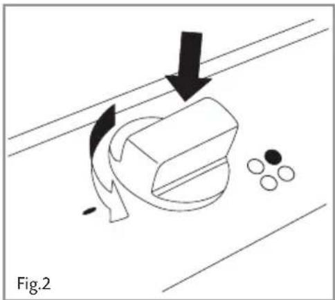
Lightly press the control knob down and turn the knob anticlockwise to the maximum position. Firmly press and hold down the control knob to begin the ignition process (a clicking sound will be heard). Hold down the control knob for a few seconds after ignition to allow the safety device to detect that the burner is lit.
-
Once the burner is lit, adjust the burner power to the required position.
The hob is fitted with a flame failure device. Hold down the control knob for a few seconds after ignition to allow the safety device to detect that the burner is lit. Flame failure devices operate by shutting off the supply of gas to the burner in the event that the flame is extinguished accidentally.
Please note:
• The ignition device should not be operated for more than 15 seconds.
- If a burner does not ignite, or turns off accidentally, turn the control knob to the 'off' position, and wait for one minute before attempting to reignite the burner.
- If the burner does not ignite, repeat the ignition process with the burner at the minimum position.
Efficient use of your Hob
The hob is equipped with burners of different sizes, designed to accommodate most shapes and sizes of pan. For best results, only use pans with flat bottoms and choose an appropriate burner depending on the size of the pan. The most efficient use of the hob is shown below, where the pan and burner are correctly chosen.
Ensure that the pans do not overlap the edge of the pan stand, or cover the control panel.

The table below shows the sizes of pan that should be used with each burner:
| Burner Size | Minimum Pan Diameter (cm) | Maximum Pan Diameter (cm) |
| Auxiliary | 12 | 14 |
| Semi-Rapid | 14 | 20 |
| Rapid | 18 | 24 |
Care and Maintenance
As the hob has a stainless steel or enamel surface, you should use a nonabrasive cleaner. Any abrasive cleaner (including Cif) will scratch the surface and could erase the control panel markings. Stainless steel can be effectively cleaned by simply using a dilute solution of water and mild detergent and drying to a shine with a clean cloth.
Over time with use, the stainless steel surface may discolour; this is normal and does not constitute a fault with this appliance. Proprietary stainless steel cleaners are available.
The enamelled parts of hobs are not suitable for cleaning in dishwashers; these should be washed by hand.
IMPORTANT:
• Steam cleaners must not be used when cleaning this appliance.
• Ensure that all parts are correctly replaced after cleaning before attempting to use the hob.
- After removing the pan stands, ensure the rubber pads are in place on the base of the pan stand before repositioning the pan stands straight and level on the hob.
What to do if you smell gas:
- Open doors and windows
- Turn the gas supply off
- Call TRANSCO on: 0800 111 999
| Burner Size | Nominal Rating (kW) | Simmer Rating (kW) | LPG Flow Rate ( lh-1 ) | |
| G30 | G31 | |||
| Auxiliary | 1.0 | 0.45 | 72.8 | 71.5 |
| Semi-Rapid | 1.85 | 0.68 | 134.6 | 132.2 |
| Rapid | 3.0 | 1.12 | 218.8 | 214.8 |
Total rated gas input : 7.7kW
Mains electrical voltage: 230 - 240Vac, 50Hz
Total rated electrical consumption: <1W
If your Hob is not working
- Check that the mains supply has not been switched off.
- Check that the fuse in the spur has not blown.
- Ensure that the burner components are not excessively soiled as this can lead to ignition problems.
Mains Electricity Connection
THIS APPLIANCE MUST BE CONNECTED TO THE MAINS SUPPLY BY A COMPETENT PERSON, USING FIXED WIRING VIA A DOUBLE POLE SWITCHED FUSE SPUR OUTLET AND PROTECTED BY A 3A FUSE.
We recommend that the appliance is connected by a qualified electrician, who is a member of the N.I.C.E.I.C. and who will comply with the I.E.E. and local regulations.
The wires in the mains lead of this appliance are coloured in accordance with the following code:
Green & Yellow = Earth, Blue = Neutral, Brown = Live.
As the colours of the wires in the mains lead for the appliance may not correspond with the coloured markings identifying the terminals connecting to the fuse spur, proceed as follows:
- The wire which is coloured green and yellow must be connected to the terminal marked E (Earth) or coloured green.
- The wire which is coloured blue must be connected to the terminal marked N (Neutral), or coloured black.
- The wire which is coloured brown must be connected to the terminal marked L (Live), or coloured red.
Note: Use a 3A Fuse
Assembly and electrical connection should be carried out by specialised personnel.
When installing this product we recommend you seek the help of another individual.

Gas Supply Requirements
IMPORTANT: THIS APPLIANCE SHOULD BE FITTED BY A GAS SAFE REGISTERED FITTER OR OTHER SUITABLY QUALIFIED PERSON.
• This installation must comply with the Gas Safety (installation and use) Regulations 1984.
- This appliance is category II2H3+ and is designed for use in the UK and Ireland. The installation must comply with the Gas Safety (installation and use) Regulations 1984.
- The CDA Group Ltd is not legally able to provide any assistance in the installation of gas appliances except to Gas Safe registered installers. Any Gas Safe registered fitter requiring help must provide their name, address and registration number. Information supplied will be validated before help is provided.
• In the event that this appliance is not installed in accordance with the above requirements, the appliance may be
- This appliance should be installed using 15mm copper pipe connected via a shut-off valve in an adjacent unit. The shut-off valve needs to be accessible in an emergency or for service purposes.
• This appliance must not be connected to a combustion gas recovery scavenging system
• The connection to the gas supply must comply with all current regulations in force.
• We are not legally able to offer advice on the installation of gas appliances to non Gas Safe registered personnel.
Ventilation
All rooms require a window or equivalent (e.g. a door) which can be opened. Some rooms require a permanent vent in addition to a window (see below).
This unit must not be used in a room which is less than 5m3 . The following table details the requirements based on the kitchen volume (L x W x H) in m3 .
| Room Volume ( m3 ) | Air Vent Required ( cm3 ) |
| 5 | 100 |
| 6 to 10 | 50 |
| 6 to 11 | No permanent vent required if a door opens to the outside |
| 11 or more | None required |
The above requirements also allow use of a gas oven and grill but if there are any other fuel burning appliances in the same room, consult the relevant British Standard (BS5440) or GAS SAFE document.
Natural Gas to LPG Conversion
This hob can be converted from natural gas to propane operation at a nominal inlet pressure of 37mbar, or butane operation at a nominal inlet pressure of 28/30mbar. This conversion must only be carried out by a competent person (i.e. a Gas Safe registered fitter).
Instructions to flt replacement injectors:
- Disconnect the appliance from the gas and electrical supplies.
- Remove burner components and pan supports.
- Remove the injectors and replace with the corresponding injector as shown in the table below.
Setting up minimum flow rates:
- Remove the control knobs.
- Turn on the LP gas supply, light the burners and turn the controls to the minimum position, as indicated by the small flame.
- Insert a 2.5mm screwdriver into the hole at the top of the tap and turn the adjustment screw fully clockwise as shown in figure 6.
- Turn the controls to maximum position then quickly to the minimum position - make sure the flame does not extinguish.
- Replace the knobs.
Required:
- 7mm AF nut spinner
- Replacement injectors
• LPG identity plate
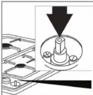
Fig.4

Required:
- 7mm AF nut spinner
- Replacement injectors
- NG identity plate
LPG to Natural Gas Conversion
This hob can be converted from propane operation at a nominal inlet pressure of 37mbar or butane operation at a nominal inlet pressure of 28/30mbar to natural gas at 20mbar. This conversion must only be carried out by a competent person (i.e. a Gas Safe registered fitter).
| Burner | LPG Injector | Natural Gas Injector |
| Rapid | 86 | 115 |
| Semi-Rapid | 67 | 97 |
| Auxiliary | 49 | 72 |
Fitting the Hob
Unpacking the hob:
Take care not to lose or mishandle any parts.
Fitting position of the hob:
This appliance must be installed a minimum of 50mm from any back wall and a minimum of 150mm away from any adjacent vertical surfaces, e.g. a tall cupboard end panel. This may be reduced to 100mm if the adjacent surface is resistant to fire (tiles or steel, for example). These dimensions are shown in Fig.5.
If fitting a cooker hood above the hob:
If a cooker hood is to be installed above the hob, the height of the hood above the hob must be at least 700mm (750mm is recommended) (Fig.6). If the instructions supplied with the hood dictate that the hood must be installed at a height greater than 700mm, then that height is the minimum required.
Wall furniture requirements:
The minimum height of any cabinet immediately above the hob is 900mm. The minimum height of any adjacent units (including light pelmets) is 400mm, unless they are manufactured from a material resistant to fire (steel, for example)
Notes:
- Do not position this appliance above a refrigeration unit. The heat generated may cause the refrigeration unit to fail.
- This appliance is designed to be installed into cabinet units capable of withstanding temperatures 65°C above ambient or greater (typically 80-90°C).
- If there is no oven to be built in below the hob it is recommended that, an isolation shelf should be fitted to protect the user from high temperatures. If the hob is to be installed above a working drawer, then a partition should be fitted to protect the
contents and user from the heat generated during use. This should be fitted at least 15mm below the hob. This panel should have a ventilation space at the rear of greater than 30mm as shown in fig. 5.
• Never place perishable foods in the cupboard below the appliance.

How to Install the Hob
How to install the hob:
Overall dimensions of the hob: Width: 580mm Depth: 500mm
Worktop cut-out dimensions: Width: 557mm Depth: 477mm
- Make the required hole in the worktop. Note that before doing this, check the instructions supplied with any cooker hood to ensure that you will have the required clearance. The cut-out (Fig 6) shows a 61.5mm gap from the wall to the cut-out edge. The distance for the hob, when fitted, to the back wall is 50mm.
- Position the hob seal, as shown in the diagram below (Fig 8), ensuring that the ends meet without overlapping. Do not use silicone type sealant.
- Secure the hob to the worktop using the fixing brackets and screws supplied, as shown in the following diagram (Fig 9). Remove any excess sealant after tightening the brackets.


Notes :

Serviced by
|C|D|A
To contact our Customer Care Department, or for Service, please contact us on the details below.


- IMPORTANT
- APPLIANCE INFORMATION
- CE DECLARATIONS OF CONFORMITY
- PLEASE NOTE
- GAS BURNERS
- CONTROL PANEL
- IGNITING THE BURNERS
- TO IGNITE THE BURNERS, FOLLOW THESE INSTRUCTIONS
- EFFICIENT USE OF YOUR HOB
- CARE AND MAINTENANCE
- WHAT TO DO IF YOU SMELL GAS
- IF YOUR HOB IS NOT WORKING
- MAINS ELECTRICITY CONNECTION
- NOTE: USE A 3A FUSE
- GAS SUPPLY REQUIREMENTS
- IMPORTANT: THIS APPLIANCE SHOULD BE FITTED BY A GAS SAFE REGISTERED FITTER OR OTHER SUITABLY QUALIFIED PERSON
- VENTILATION
- NATURAL GAS TO LPG CONVERSION
- INSTRUCTIONS TO FLT REPLACEMENT INJECTORS
- SETTING UP MINIMUM FLOW RATES
- REQUIRED
- LPG TO NATURAL GAS CONVERSION
- FITTING THE HOB
- UNPACKING THE HOB
- FITTING POSITION OF THE HOB
- IF FITTING A COOKER HOOD ABOVE THE HOB
- WALL FURNITURE REQUIREMENTS
- NOTES
- HOW TO INSTALL THE HOB
- C|D|A
Brand : MATRIX
Model : MHG100SS
Category : Cooker