VIP-172L - Intercom Valcom - Free user manual and instructions
Find the device manual for free VIP-172L Valcom in PDF.


| Product Type | Video Intercom |
| Dimensions (approx.) | 200 x 150 x 50 mm (7.9 x 5.9 x 2.0 in) |
| Weight (approx.) | 0.5 kg (1.1 lbs) |
| Power Supply | 12V DC |
| Display | 7-inch color TFT LCD |
| Camera | Built-in CMOS, night vision |
| Audio | Full duplex speakerphone |
| Door Lock Control | Electric strike release |
| Main Functions | Audio/video communication, door unlock, monitor, intercom |
| Mounting | Wall-mounted indoor unit |
| Material | ABS plastic |
| Operating Temperature | -10°C to 50°C (14°F to 122°F) |
| Storage Temperature | -20°C to 60°C (-4°F to 140°F) |
| Humidity | Up to 85% non-condensing |
| Included Accessories | Mounting bracket, screws, user manual |
| Cleaning and Maintenance | Wipe with a soft dry cloth; avoid liquid cleaners |
| Safety | Indoor use only; professional installation recommended |
| Spare Parts and Repairability | Contact Valcom support for replacement parts |
| Compliance | CE, FCC |
| Warranty | 1 year limited |
| General Information | Brand: Valcom, Model: VIP-172L, Category: Intercom |
Frequently Asked Questions - VIP-172L Valcom
User questions about VIP-172L Valcom
0 question about this device. Answer the ones you know or ask your own.
Ask a new question about this device
Download the instructions for your Intercom in PDF format for free! Find your manual VIP-172L - Valcom and take your electronic device back in hand. On this page are published all the documents necessary for the use of your device. VIP-172L by Valcom.
USER MANUAL VIP-172L Valcom
VIP-172L IP DoorPhone/Intercom
INTRODUCTION
The VIP-172L IP Talkback Doorphone/Intercom allows communication to Valcom FXS units (VIP-811, -812, -814) and SIP Based telephone systems via a managed IP-based LAN/WAN.
SPECIFICATIONS
Access Methods
• PBX, FXO Port w/VIP-811
• POTS telephone set w/VIP-811
• Valcom M Cast Page Group
- SIP – enabled telephone system
Features
• RJ-45 for network connection
• 1 Form C contact
• LED Status Indicator
• Network activity LEDs
• 802.3af compliant
• Door Opening Contact Provided
Dimensions/Weight V-172L-VR
• 4.5" H x 4.5" W x 1.75" D
(11.43cm H x 11.43cm W x 4.45cm D)
• Weight: 1.68 lbs. (0.76 kg)
Dimensions/Weight V-172L-BR/ST
- 4.5" H x 4.5" W x 1.3" D
(11.43cm H x 11.43cm W x 3.3cm D)
• Weight: .55 lbs. (0.25 kg)
Nominal Specifications
Input Impedance: 600 Ohms
Input Level: -10dBm
Output Impedance: 600 Ohms
Output Level: -10dBm nominal
Relay Current: 1 AMP @ 24VDC
Nominal Power Requirements
Via 802.3af PoE Ethernet Switch: Class 3 (12.95W)
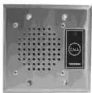
VIP-172L-BRASS/SS
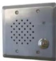
VIP-172L-VRSS
Environment
VIP-172L Network Interface
Temperature: 0 to +40°C
Humidity: 0 to 85% non-precipitating
VIP-172L Doorplate:
Suitable for indoor or outdoor installation
Packing List
| Qty | Item |
| 1 | VIP-172L Network Interface |
| 1 | VIP-172L Door plate |
| 1 | VSP Document |
| 4 | Tamper Hardware (VRSS unit only) |
| 4 | SS Screws (Brass/SS) |
| 1 | Setup CD |
Precautionary Designations
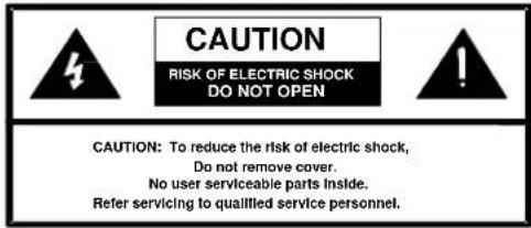
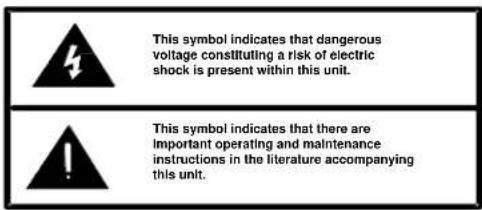
FCC Information
This equipment has been tested and found to comply with the limits for a Class A digital device, pursuant to Part 15 of the FCC Rules. These limits are designed to provide reasonable protection against harmful interference when the equipment is operated in a commercial environment. This equipment generates, uses and can radiate radio frequency energy and if not installed and used in accordance with the instruction manual, may cause harmful interference to radio communications. Operation of this equipment in a residential area may cause harmful interference in which case the user will be required to correct the interference at his own expense.
INSTALLATION
Operation:
The VIP-172L provides door intercom access via network connection to customer telephone system or stand alone telephone set. Interface to customer telephone system can be via SIP registration or FXO port (with VIP-811). Pressing the call button on the door plate initiates a call to one of the above telephone system interfaces, and the call assurance LED on the door plate begins to flash. When the call is answered, a hands-free communications path is established to the door plate, and the call assurance LED on the door plate changes to solid. At any time during the call if the # key is pressed, the form C relay on the door plate operates for 3 seconds for activation of customer supplied door entry equipment.
Mounting
For enhanced protection against static electrical discharge, it is recommended the faceplate shipped with the VIP-172L be installed into a grounded electrical box.
The VIP-172L Doorplate is designed for double gang FD electrical box mounting and must be within 300 meters of the VIP-172L Network Interface. See NEMA OS 3-2002 sec.1.2.3.5 for FD box specifications.
The VIP-172L Network Interface is designed for wall or table mounting and must be within 100 meters of the network switch.
Table: Provided with the VIP-172L are four rubber stick on feet. Peel these feet off their carrier backing and place at the four corners of the bottom of the unit.
Wall: Using the template and wood screws provided, secure the VIP-172L Network interface to the wall.
Power Connections
The only method of powering a VIP-172L Network Interface is via a power over Ethernet switch or power injector meeting the 802.3af specification.
Make all required signal connections before connecting to Ethernet switch or power injector meeting the 802.3af specification.
Network Connection
The VIP-172L Network Interface has one CAT-5 RJ-45 NETWORK connector and one CAT-5 RJ-45 DOOR PLATE connector on the front panel.
Use the supplied CAT-5 patch cable to connect the NETWORK connector of the VIP-172L Network Interface to an Ethernet switch.
Signal Connections
Connect CAT-5 RJ-45 using EIA/TIA 568B Standard to the DOOR PLATE connector of the VIP-172L Network Interface then to the RJ-45 connector of the VIP-172L Door Plate.
Door Relay Connections
Access to the form C relay is provided via a three pin screw terminal block on the VIP-172L Door plate. The common contact is the middle terminal with the normally open contact closest to the RJ-45 Connector. Normally closed contact is furthest from the RJ-45 connector. Relay contacts are rated for 1A @ 24VDC.
Aux Input
Aux input on the VIP-172L Network Interface accepts line level audio such as background music and broadcasts it through the door plate speaker. When the call button is pressed, the aux input is muted and remains muted until the call is terminated.
Status Indicator Lights
The VIP-172L Door plate is equipped with a status indicator LED. LED flashes when the call button is pressed and steady when the call is connected.
The VIP-172L Network Interface has 3 status indication lights on the side panel:
STATUS: Flashes during normal operation, and solid when unit in reset.
LINK: Indicates 100 Mbit Ethernet connection when illuminated. No activity indicates 10 Mbit connection.
ACT: Indicator flashes to indicate network activity.
TECHNICAL ASSISTANCE
Assistance in troubleshooting is available from the factory. Call (540) 563-2000 and press 1 for Technical Support or via email at support@valcom.com.
When requesting assistance, you should include all available information. It is strongly suggested that you go to the web site and follow the trouble resolution procedure at http://voip.valcom.com.
Valcom equipment is not field repairable. Valcom, Inc. maintains service facilities in Roanoke, VA. Should repairs be necessary, attach a tag to the unit clearly stating your company name, address, phone number, contact person and the nature of the problem. Send the unit to:
Valcom, Inc.
Repair & Return Dept.
5614 Hollins Road
Roanoke, Va. 24019-5056
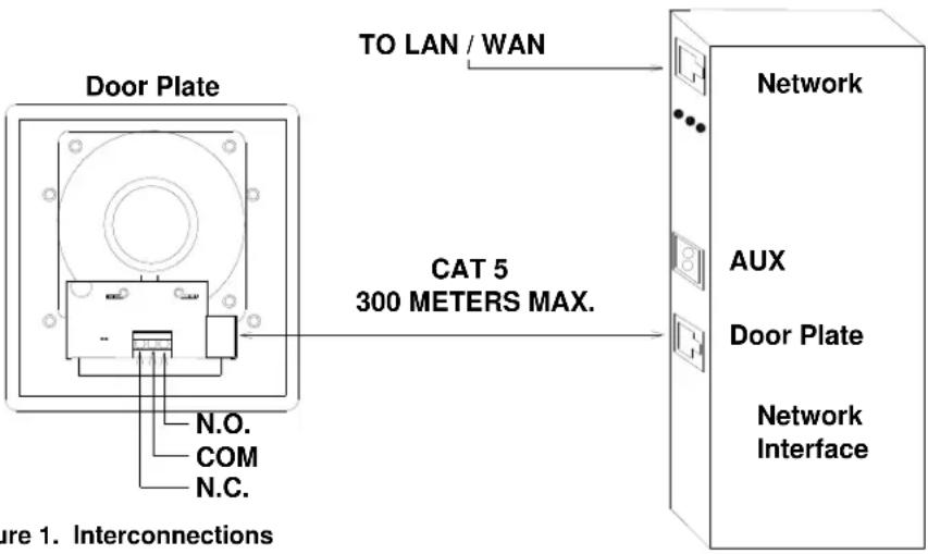
Figure 1. Interconnections
VALCOM LIMITED WARRANTY
Valcom, Inc. warrants its products only to the original purchaser, for its own use, to be free from defects in materials and workmanship under conditions of normal use and service for a period of one year from the date of shipment. This Limited Warranty obligation shall be limited to the replacement, repair or refund of any such defective device within the warranty period, provided that:
- inspection by Valcom, Inc. indicates the validity of the claim;
- the defect is not the result of damage, misuse or negligence after the original shipment;
- the product has not been altered in any way or repaired by others and that factory sealed units are unopened (a service charge plus parts and labor will be applied to units defaced or physically damaged);
- freight charges for the return of products to Valcom are prepaid;
- all units 'out of warranty' are subject to a service charge. The service charge will cover minor repairs (major repairs will be subject to additional charges for parts and labor).
This Limited Warranty is in lieu of and excludes all other warranties, expressed or implied and in no event shall Valcom, Inc. be liable for any anticipated profits, consequential damages, loss of time or other losses incurred by the buyer in connection with the purchase, operation, maintenance, installation, removal or use of the product. The maximum liability of Valcom under this warranty is limited to the purchase price of the specific Product covered by the warranty.
Disclaimer. Except for the Limited Warranty provided herein, the product is provided "as-is" without any warranty of any kind whatsoever including, without limitation, any WARRANTY OF MERCHANTABILITY, FITNESS FOR A PARTICULAR PURPOSE OR NON-INFRINGEMENT.
This warranty specifically excludes damage incurred in shipment. In the event a product is received in damaged condition, the carrier should be notified immediately. Claims for such damage should be filed with the carrier involved in accordance with the F.O.B. point.
Headquarters:
Valcom, Inc.
5614 Hollins Road Roanoke, VA 24019-5056
Phone: (540) 563-2000 FAX: (540) 362-9800
- VIP-172L IP DoorPhone/Intercom
- INTRODUCTION
- SPECIFICATIONS
- Access Methods
- Features
- Dimensions/Weight V-172L-VR
- Dimensions/Weight V-172L-BR/ST
- Nominal Specifications
- Nominal Power Requirements
- Environment
- VIP-172L Network Interface
- VIP-172L Doorplate:
- Precautionary Designations
- FCC Information
- INSTALLATION
- Operation:
- Mounting
- Power Connections
- Network Connection
- Signal Connections
- Door Relay Connections
- Aux Input
- Status Indicator Lights
- TECHNICAL ASSISTANCE
- VALCOM LIMITED WARRANTY
Brand : Valcom
Model : VIP-172L
Category : Intercom