
PXGMSUPS - Network card / adapter EATON - Free user manual and instructions
Find the device manual for free PXGMSUPS EATON in PDF.


| Product Type | Network Management Card |
| Brand | Eaton |
| Model | PXGMSUPS |
| Dimensions (W x H x D) | 6.6 x 1.7 x 5.1 inches (168 x 43 x 130 mm) |
| Weight | 0.5 lb (0.23 kg) |
| Power Supply | Powered via UPS auxiliary port |
| Network Interface | 10/100 Mbps Ethernet RJ-45 |
| Protocols | SNMP v1/v2c/v3, HTTP/HTTPS, SSH, Telnet |
| Management | Remote UPS monitoring and control via web browser or NMS |
| Supported UPS | Eaton UPS with network card slot |
| Operating Temperature | 32°F to 122°F (0°C to 50°C) |
| Humidity | 0% to 95% non-condensing |
| LED Indicators | Link/Activity, Status, Fault |
| Firmware Upgrade | Via network connection |
| Security | SSL/TLS, user authentication, SNMPv3 encryption |
| Maintenance | Clean with dry cloth; no user-serviceable parts |
| Safety | ESD sensitive; handle with care during installation |
| Spare Parts | Not applicable; unit not user-repairable |
| Certifications | CE, FCC, RoHS |
Frequently Asked Questions - PXGMSUPS EATON
User questions about PXGMSUPS EATON
0 question about this device. Answer the ones you know or ask your own.
Ask a new question about this device
Download the instructions for your Network card / adapter in PDF format for free! Find your manual PXGMSUPS - EATON and take your electronic device back in hand. On this page are published all the documents necessary for the use of your device. PXGMSUPS by EATON.
USER MANUAL PXGMSUPS EATON
Eaton® Power Xpert® Gateway Minislot PXGMS UPS Card
User's Guide
Class B EMC Statements
FCC Part 15
This equipment has been tested and found to comply with the limits for a Class B digital device, pursuant to part 15 of the FCC Rules. These limits are designed to provide reasonable protection against harmful interference when the equipment is operated in a commercial environment. This equipment generates, uses, and can radiate radio frequency energy and, if not installed and used in accordance with the instruction manual, may cause harmful interference to radio communications. Operation of this equipment in a residential area is likely to cause harmful interference in which case the user will be required to correct the interference at his own expense.
Requesting a Declaration of Conformity
Units that are labeled with a CE mark comply with the following harmonized standards and EU directives:
• Harmonized Standards: EN 62040-2:2006
EN 55022:2010 Class B, EN 55024:2010 FCC Part 15 Sub-part B Class B
• EU Directive: 2004/108/EC, Council Directive relating to electromagnetic compatibility
The EC Declaration of Conformity is available upon request for products with a CE mark. For copies of the EC Declaration of Conformity, contact:
Eaton Power Quality Oy
Koskelontie 13
FIN-02920 Espoo
Finland
Phone: +358-9-452 661
Fax: +358-9-452 665 68
Eaton, Power Xpert Architecture, and Power Xpert are registered trademarks and PowerChain Management is a trademark of Eaton Corporation or its subsidiaries and affiliates. Microsoft, Windows, Internet Explorer, and Excel are registered trademarks of Microsoft Corporation in the United States and other counties. Freescale is a trademark of Freescale Semiconductor, Inc. Google Chrome is a trademark of Google Inc. IBM is a registered trademark of International Business Machines Corporation. Linux is a registered trademark of Linus Torvalds. Micrel is a registered trademark of Micrel, Inc. Modbus is a registered trademark of Schneider Automation. Mozilla and Firefox are registered trademarks of the Mozilla Foundation. OpenView is a trademark of Hewlett-Packard Company. Phillips is a registered trademark of Phillips Screw Company. All other trademarks are property of their respective companies.
©Copyright 2012 Eaton Corporation, Raleigh, NC, USA. All rights reserved. No part of this document may be reproduced in any way without the express written approval of Eaton Corporation.
Table of Contents
1 INTRODUCTION
Eaton Power Xpert Architecture 1
2 GETTING STARTED
Installation Checklist 2
Install the Card 3
Connect the Card to the Computer....4
Install the USB Driver Software (Windows XP).... 6
Install the USB Driver Software (Windows 7)....11
Verify IP Address Assignment 14
Manually Assign an IP Address. 15
IPv6 Address Assignments....16
Disable Internet Explorer Compatibility Mode 17
Network Configuration 19
Important Security Information.... 20
3 CONFIGURING THE CARD
Navigating the Home Page 22
Identifying Monitored Equipment 24
Device Data Page Operations 25
Configuring Tasks Essential to Initial Configuration 27
Changing the Passwords 27
Setting the Date and Time 28
Configuring SNMP Options....29
Community Strings and Trap Recipients 29
Changing SNMP Access 30
System Location and System Contact....30
Management from an SNMP NMS 31
Configuring Modbus TCP/IP Options 31
Configuring BACnet/IP 32
Editing BACnet IP Settings 32
Configuring BACnet/IP Options 33
Download BACnet/IP EPICS File 33
Configuring HTTP and HTTPS 34
Configuring Automatic Shutdown of UPS-Protected Computers ..... 34
Configuring Shutdowns for a UPS 34
Shutdown Clients 35
Managing UPS Power....35
Turning the UPS Load On and Off 35
Scheduling a UPS Shutdown and Restart 36
Configuring E-Mail Notification 36
Configuring EMP Settings....38
Saving and Restoring Configuration Settings 39
Creating a Backup 39
Restoring a Backup 39
DIP Switch Description 41
Alarm Notices 42
Generating Log Files 43
Data Log 43
Interval Log 44
Event Log. 44
System Log 44
UPS History Log 44
UPS Battery Test Log 45
Erasing a Log 45
Upgrading the Card's Firmware 45
5 ROOT CERTIFICATE AUTHORITY INSTALLATION
Installing Root CA with Windows Internet Explorer 7 and Internet Explorer 8. . 46
Installing Root CA with Mozilla Firefox 51
Installing Root CA with Google Chrome 53
6 MIB FILES
Selecting a UPS MIB File 59
Powerware UPS MIB 60
RFC 1628 UPS MIB 60
Eaton EMP MIB 61
Eaton Alarms+Traps MIB 61
Eaton OID Assignments 61
Entity MIB Files....61
Selecting the UPS Trap Type 61
7 MODBUS REMOTE TERMINAL UNIT (RTU) CONFIGURATION
Wiring the PXGMS UPS Card RS-485 Port 62
Configure Modbus Serial Port and Mappings 63
Access to RTU Registers 64
8 MODBUS REGISTERS FOR TCP AND RTU
Obtaining the Modbus Register Map 65
Returning Modbus TCP Error Codes....65
Returning Modbus Serial Error Codes....66
Modbus Register Addressing 66
Modbus Function Codes 66
Data Formats 67
Data Addressing 67
UPS Modbus TCP Unit ID Numbers 68
UPS Registers and Alarms 68
UPS Registers (FC 04) 68
UPS Alarms (FC 02) 69
EMP (FC 04) 70
Time or Date (FC 04)....70
9 SPECIFICATIONS
10 SERVICE AND SUPPORT
Two-Year Limited Warranty (US and Canada) 73
Chapter 1 Introduction
The Eaton® Power Xpert® Gateway Minislot (PXGMS) UPS Card provides Web-enabled, real-time monitoring of Eaton 93PM and Eaton 93PR (future release) uninterruptible power systems (UPSs) through standard Web pages, Power Xpert software, Intelligent Power Manager (IPM), Intelligent Power Protector (IPP), or third-party software. An integral part of the Eaton Power Xpert Architecture®, which provides end-to-end PowerChain Management™ solutions, the PXGMS UPS Card provides a central point to connect UPSs to the Ethernet network.
Network managers can view critical downstream device information, such as status, power, energy, and power quality data with an easy-to-use interface.
The PXGMS UPS Card has the following features:
- Web-enabled UPSs – view data from any location with a Web browser.
• Real-time power monitoring – view critical device data and make informed network management decisions. - Integrated communications with Eaton's Power Xpert software – monitor power devices in real time through Power Xpert software.
- Simple Network Management Protocol (SNMP) support – integrate and manage your UPS with third party network management software.
- Power quality data using Modbus® Transmission Control Protocol (TCP) – use this open communication protocol to communicate with standard building management systems.
- Modbus Remote Terminal Unit (RTU) – uses a two-wire serial communication protocol to communicate with the Building Management System.
- BACnet/IP communication – provides device interface with Building Automated Systems (BASs)
- Easy installation – install the PXGMS UPS Card while the UPS is online, maintaining the highest system availability.
- Field upgradable – use the Web interface to easily upgrade the card's firmware in the field.
Eaton Power Xpert Architecture
Eaton Power Xpert Architecture provides the framework to unify the entire power system. It connects power systems with communication and management systems to provide a holistic approach to the entire power system. This strategic system-level focus is integral to PowerChain Management solutions. It provides increased reliability, cost efficiencies, enhanced safety and risk mitigation, and allows for the more effective use of capital. Eaton Power Xpert Architecture is comprised of both software and hardware components including meters, gateways, time servers, and connectivity devices.

NOTE
If you have completed all sections in the Power Xpert Gateway Minislot (PXGMS) UPS Card Quick Start Instructions, proceed to "Configuring the Card" on page 21.
This section explains:
- Checklist items needed for installation
- Installing the card
- Connecting the card to the computer
• Installing the USB Driver Software (Windows XP and Windows 7)
• Verifying or assigning the IP address - Assigning IPv6 address
- Configuring the network settings
• Security information
Installation Checklist
- Verify that the following items are available:
Power Xpert Gateway Minislot (PXGMS) UPS Card package contents
□ Phillips ^® screwdriver
□ Available USB port on a computer running Microsoft® Windows®
Web browser (Microsoft Internet Explorer ^ version 8.0 and higher, Mozilla ^ Firefox ^ , or Google Chrome ^TM are recommended)
- If you are going to use Dynamic Host Configuration Protocol (DHCP), provide your local network administrator with the card's MAC address. The MAC address is located on a label on the bottom of the card.
□ MAC Address ____ - If you are not going to use DHCP to provide any of the settings listed below, contact your local network administrator for the settings. Select DHCP or enter the values for manual configuration in the table below:
Either Provided
| Item | by DHCP* Or Manual Configuration | |
| IPv4 | ☐ | Card IP Address: ________ |
| Netmask: ________ | ||
| Gateway: ________ | ||
| DNS – Name Servers | ☐ | Name Server #1: ________ |
| Name Server #2: ________ | ||
| Name Server #3: ________ | ||
| DNS – Domain | ☐ | Domain: ________ |
* The network administrator normally sets up the DHCP server to provide a static IP address each time the card makes a DHCP request.
- If you need e-mail functionality, obtain the SMTP mail server's IP address or host name. If using the SMTP host name, verify that you also have the Name Server IP address (see Step 3).
☐ SMTP (mail server) IP Address or Host Name ____
Install the Card

NOTE
The hot-swappable PXGMS UPS Card can be installed without turning off the UPS or disconnecting the load.
To install the PXGMS UPS Card:
- Verify that all six DIP switches on the card are in the OFF position (see Figure 1).
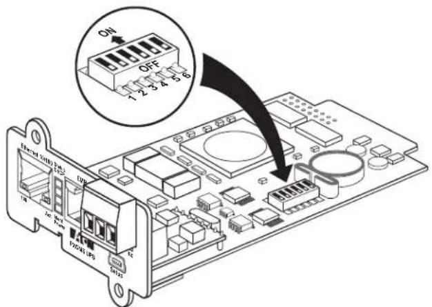
Figure 1. Verify DIP Switches are OFF
- Remove the blank Minislot cover from the UPS. Retain the screws.

NOTE
If there is another card already installed with an attached communication cable, disconnect the cable and then remove the card.
-
If not already done, record the MAC address for future reference (see Step 2 on page 2).
-
To prevent electrostatic discharge (ESD), place one hand on a metal surface, such as the UPS rear panel.
-
Slide the card into the open slot and secure with the screws removed in Step 2 (see Figure 2).
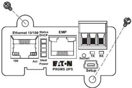
Figure 2. Secure the PXGMS Card
- Connect an active Ethernet cable (not supplied) to the Ethernet 10/100 connector on the PXGMS UPS Card (see Figure 3).
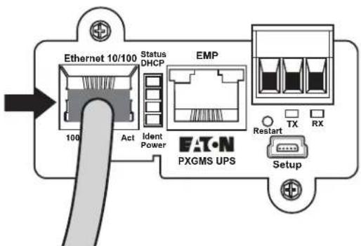
Figure 3. Install the Ethernet Cable
Connect the Card to the Computer
To connect the card to the computer:
-
Go to www.eaton.com/pxgms and click the Power Xpert Gateway Minislot UPS Card link beside the PXGMS UPS Card photograph.
-
On the Features tab, click the Download Configuration File link to download the powerxpert.inf file. Note the location of the downloaded file on your computer so you can use it later.
-
Plug the USB cable into the Setup port on the card (see Figure 4).
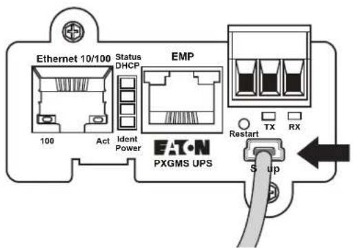
Figure 4. Install the USB Cable
- Plug the other end of the USB cable into the USB port on the computer.
- The Windows operating system detects new hardware (see Figure 5).

Figure 5. Found New Hardware Wizard – Welcome Window

NOTE
If a message displays indicating that the device driver software was not successfully installed, click Ignore.
-
The steps for installing the USB driver software are determined by the type of operating system running on your computer:
-
For Windows XP, continue to "Install the USB Driver Software (Windows XP)" on page 6.
- For Windows 7, continue to "Install the USB Driver Software (Windows 7)" on page 11.
Install the USB Driver Software (Windows XP)
To install the USB driver software on a computer running Windows XP:
- On the Welcome window, select No, not this time and click Next (see Figure 6).
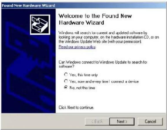
Figure 6. Found New Hardware Wizard – Welcome Window
- Select Install from a list or specific location (Advanced) and click Next (see Figure 7).
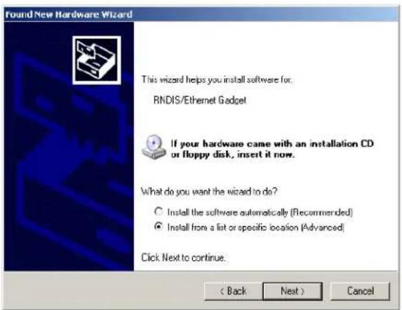
Figure 7. Found New Hardware Wizard – Install Software Window
- Select Don't search. I will choose the driver to install and click Next (see Figure 8).
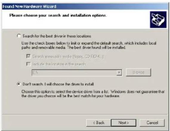
Figure 8. Found New Hardware Wizard – Installation Options Window
- Select Network adapters and click Next (see Figure 9).
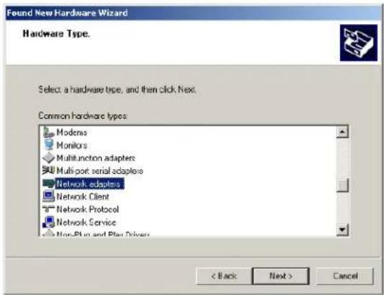
Figure 9. Found New Hardware Wizard – Hardware Type Window
5. Select Have Disk... and click Next (see Figure 10).
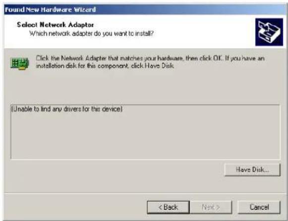
Figure 10. Found New Hardware Wizard – Select Network Adapter Window
6. Click Browse (see Figure 11).

NOTE
Disregard the instruction to insert the manufacturer's installation disk. You will not install from a disk. The driver will be installed from the powerxpert.inf file you downloaded in Step 2 on page 4.
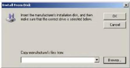
Figure 11. Install From Disk Window
-
In the Locate File window, navigate to the powerxpert.inf file you downloaded in Step 2 on page 4 (see Figure 12).
-
Select the file and click Open.
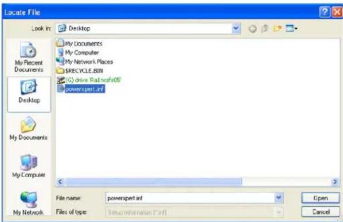
Figure 12. Locate File Window
-
In the Install from Disk window, the path to the powerxpert.inf file displays in the Copy manufacturer's file from box. Click OK.
-
Select the most recent Linux USB Ethernet/RNDIS Gadget and click Next (see Figure 13).
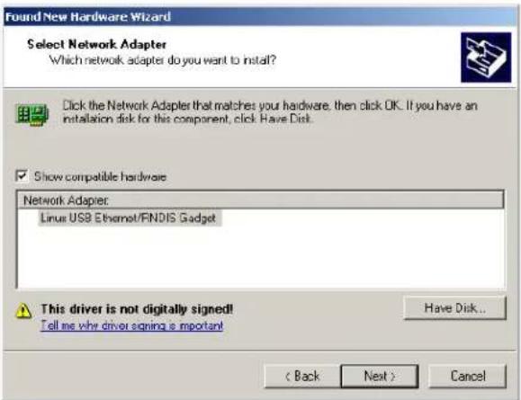
Figure 13. Found New Hardware Wizard – Select Network Adapter Window

NOTE If the caution message shown in Figure 14 displays, click Continue Anyway.
![Hardware Installation The software you are installing for this hardware Linux USB Ethernet/RNDIS Gadget has not passed Windows Logo testing to verify its compatibility with Windows KP. [Tell me why this testing is important] Continuing your installation of this software may impair or destabilize the correct operation of your system either immediately or in the future. Microsoft strongly recommends that you stop this installation now and contact the hardware vendor for software that has passed Windows Logo testing. Continue Anyway STOP Installation](/content/2026/05/960225/images/99c3b35bbfdae9805141d4e8c91659356e886715f58eb7642256a892506f75c7.jpg)
Figure 14. Caution Message
- The wizard installs the software for the USB driver. Click Finish to close the wizard (see Figure 15).
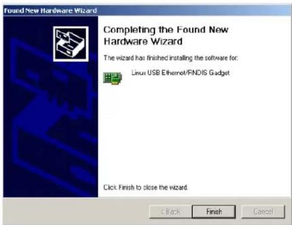
Figure 15. Found New Hardware Wizard – Finished Installing the Software Window
- Open the Network Connections window from the Windows Control Panel to verify that the installation was successful.
If "Linux USB Ethernet/RNDIS Gadget" is listed in the Device Name column, the USB driver has been successfully installed (see Figure 16).
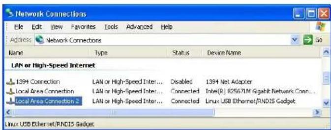
Figure 16. Network Connections Window

NOTE
By default, the PXGMS UPS Card requests an IP address through DHCP when the card is connected to a network.
- Either verify the assigned IP address or manually enter a fixed IP address:
- To verify the IP address assigned through DHCP, continue to "Verify IP Address Assignment" on page 14.
- To manually enter a fixed IP address for the card's network connection, continue to "Manually Assign an IP Address" on page 15.
Install the USB Driver Software (Windows 7)
To install the USB driver software on a computer running Windows 7:
-
Open the Control Panel and select Hardware and Sound (see Figure 17).
-
Under Devices and Printers, select Device Manager to open the Device Manager window.
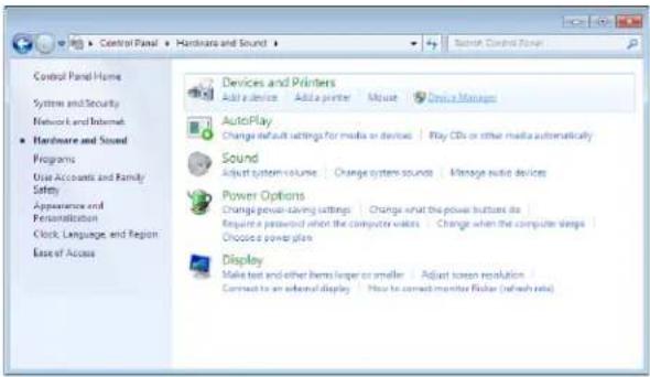
Figure 17. Control Panel Window – Hardware and Sound
-
Expand Other devices and select RNDIS/Ethernet Gadget (see Figure 18).
-
Right-click Update Driver Software.

Figure 18. Device Manager Window
- Select Browse my computer for driver software (see Figure 19).
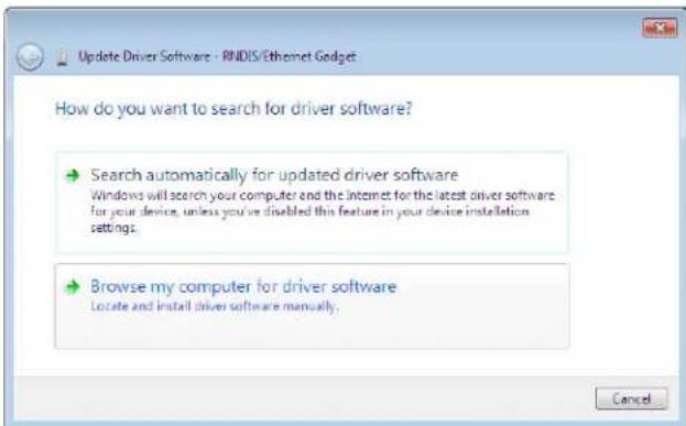
Figure 19. Update Driver Software Window – Search Method
- Click Browse (see Figure 20).
- In the Locate File window, navigate to the powerxpert.inf file you downloaded in Step 2 on page 4.
- Select the file and click Open.
- The path to the powerxpert.inf file displays in the Search for driver software in this location box. Click Next (see Figure 20).
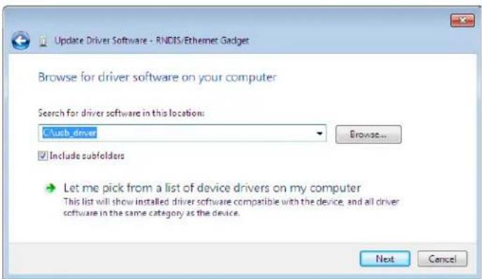
Figure 20. Update Driver Software Window – Browse for Driver Software

NOTE
If the message "Windows can't verify the publisher of this driver software" displays, select Install this driver software anyway (see Figure 21).
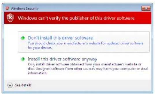
Figure 21. Windows Security Message
- When the driver software is updated successfully, the message "Windows has successfully updated your driver software" displays (see Figure 22).
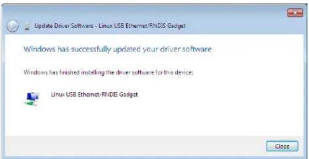
Figure 22. Update Driver Software Window – Update Successful
- To verify the device is installed:
a. Go to Control Panel > Hardware and Sound > Devices and Printers > Device Manager.
b. Expand Network adapters.
c. Verify that Linux USB Ethernet/RNDIS Gadget is listed under Network adapters (see Figure 23).
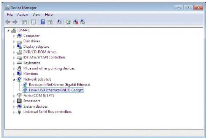
Figure 23. Device Manager Window – Verify Device Installation
- From the Start menu, go to All Programs > Accessories > Command Prompt to open a Command Prompt window.
- Enter ipconfig /all. The adapter IP addressing information displays (see Figure 24).
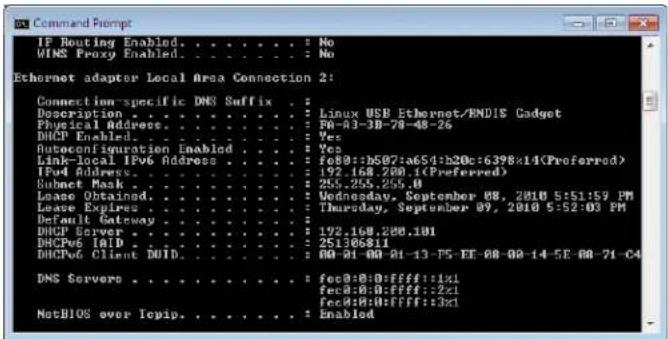
Figure 24. Command Prompt Window – Adapter IP Address Information
- Verify that the assigned IPv4 address is in the 192.168.200.x range, where "x" is typically "1."
-
Either verify the assigned IP address or manually enter a fixed IP address:
-
To verify the IP address assigned through DHCP, continue to "Verify IP Address Assignment" on page 14.
- To manually enter a fixed IP address for the card's network connection, continue to "Manually Assign an IP Address" on page 15.
Verify IP Address Assignment
To verify the IP address assignment:
- Connect to the card over the USB cable:
a. Open your Web browser.
b. Enter: http://192.168.200.101
You are prompted to log on.
- Log on as administrator. The default username and default password are "admin." The PXGMS UPS Card Web page displays.

NOTE
If you receive a browser incompatibility warning, the Internet Explorer browser is running in compatibility mode. To disable compatibility mode, go to "Disable Internet Explorer Compatibility Mode" on page 17.
- Select Network from the Configuration menu. The Network page displays (see Figure 25).
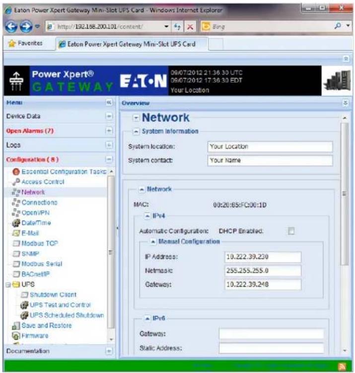
Figure 25. PXGMS Card Network Page
-
Verify that the network settings match those on the Installation Checklist on page 2.
-
Verify network communication:
a. Clear the DHCP Enabled check box. The text that was dimmed in the Manual Configuration section is now available.
b. Copy the IP address.
c. Open a second browser and paste the IP address in the Address bar and click Go. If the assigned IP address is working, you are prompted to log on.
d. Log on as administrator. The default username and default password are "admin." The PXGMS UPS Card Web page displays.
Manually Assign an IP Address
To manually enter a fixed IP address for the card:
- Connect to the card over the USB cable:
a. Open your Web browser.
b. Enter: http://192.168.200.101
You are prompted to log on.
- Log on as administrator. The default username and default password are "admin." The PXGMS UPS Card Web page displays.

NOTE
If you receive a browser incompatibility warning, the Internet Explorer browser is running in compatibility mode. To disable compatibility mode, go to "Disable Internet Explorer Compatibility Mode" on page 17.
- Select Network from the Configuration menu. The Network page displays (see Figure 25 on Page 15).
- Clear the DHCP Enabled check box to enable manual configuration.
- Enter the IP, Netmask, and Gateway addresses in the Manual Configuration section and click Apply.
- Click OK to confirm.
- If you are using a host name, or host names, for controlling access to the card, type the server IP address in the Name Server box. Up to three IP addresses can be entered.
- Click Apply.
- Click OK to confirm.
- Verify network communication:
a. Copy the IP address you entered in Step 5.
b. Open a second browser and paste the IP address in the Address bar and click Go. If the assigned IP address is working, you are prompted to log on.
c. Log on as administrator. The default username and default password are "admin." If the PXGMS UPS Card Web page displays, the fixed IP Address is correct.
IPv6 Address Assignments
There are four sets of IPv6 addresses that can be assigned to the card:
• Gateway. Manually assigned IPv6 Gateway address.
- Link-Local Address. The Link-Local Address is a permanent address assigned to the card.
- Automatic Address. This address only displays if the card is connected to a network router that supports stateless address autoconfiguration.
- Static Address. Manually assigned fixed IPv6 address.

NOTE Only the Gateway and Static addresses are user-configurable. The Link-Local and Automatic addresses are automatically populated.

NOTE Dynamic Host Configuration Protocol for IPv6 (DHCPv6) is not supported.
To manually enter a fixed IP address for the card:
- Open your Web browser and enter: http://192.168.200.101/. You are prompted to log on.
- Log on as administrator. The username and default password is "admin". The PXGMS UPS Card Web page displays.
- Select Network from the Configuration menu. The Network page displays (see Figure 25 on page 15).
- Enter the Static and Gateway addresses in the IPv6 section.
- Click Apply.
- Click OK to confirm.
Disable Internet Explorer Compatibility Mode
Internet Explorer 8 introduced the compatibility mode so that Web pages designed for older versions would display properly. If you are receiving the compatibility warning (see Figure 26), the browser compatibility mode should be disabled.
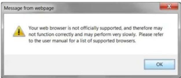
Figure 26. Compatibility warning window
To disable the compatibility mode:
- Open your Web browser.
- In the Menu bar select Tools > Compatibility View Settings. The Compatibility View Settings window opens (see Figure 27).
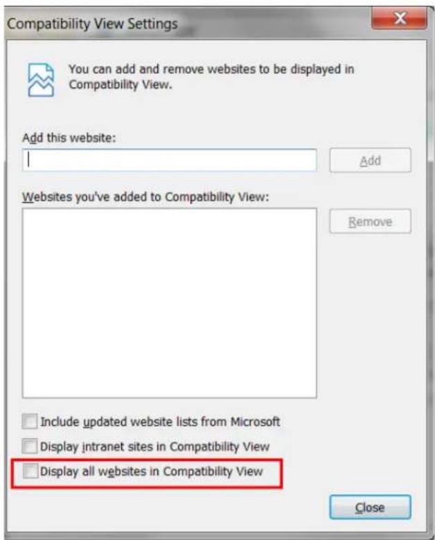
Figure 27. Compatibility view settings window
- Clear the Display all websites in Compatibility View check box to disable compatibility mode and click Close.
- Close and re-open your browser so that the changes take effect.
Network Configuration
If you know the card's IP address, you can configure the network settings from the card's Web page. To configure the network settings:
-
Open a Web browser, type the IP address of the card, and select Go (see Figure 28).
-
Log on as administrator. The username and default password is "admin".
The PXGMS UPS Card's initial page displays.
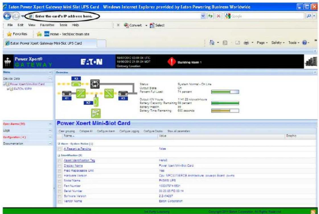
Figure 28. Initial Page – Device Overview and Summary
-
Select Network from the Configuration menu to open the Network configuration page.
-
You can enable or disable DHCP control by selecting or clearing the check box. The default is DHCP enabled.
-
If you want the card to access other network servers (such as an SMTP server) by host name, type the server IP address in the Name Server field. Up to three IP addresses can be entered.
-
If you will be using Simple Network Management Protocol (SNMP), identify the physical location of the installed card in the System location field. This value also displays in the banner.
-
Enter the information to identify someone to contact with questions about this device in the System contact field. For example, you can type a person's name, phone number, department, e-mail address, or physical location.
-
You can also modify the card's IP address, the subnet mask, and the gateway address (IP Address, Netmask, and Gateway fields).
-
To test the card's network connection to other network servers, such as an SMTP server, you can ping (request acknowledgement from) the host. Enter the IP address or hostname in the Ping test field and then click Test.
-
Click Apply to save the settings or Discard to cancel the changes.
- Continue to "Configuring the Card" on page 21 for additional configuration options.
Important Security Information
By default, the PXGMS UPS Card is configured to prevent unauthorized SNMP, Modbus TCP and BACnet/IP access by computers that are not on the Trusted IPs/Hostnames list.
If you are using SNMP, Modbus TCP or BACnet/IP, see "Changing SNMP Access" on page 30 to add specific IP addresses or host names of trusted computers.
Chapter3 Configuring the Card
| NOTE | If DHCP is disabled and you will be using host names for servers, such as the mail server, Network Time Protocol (NTP) server, SNMP hosts, Modbus TCP hosts, or trap recipients, “enter” the IP address of your network DNS Server (see “Network Configuration” on page 19). |
| i | NOTE | To configure Modbus RTU see page 62. |
| IMPORTANT |
| You must be logged on as admin to configure the card. To prevent unauthorized access after you finish configuring the card, close the browser. |
| NOTE Some versions of Google’s Chrome browser may require clearing the browser cache in order to correctly log in as a different user when the browser is re-opened and re-connected to the card. |
This section explains:
• Navigating the card's Web page
• Identifying monitored equipment
- Configuring essential tasks
- Changing the passwords
- Setting the date and time
- Configuring SNMP options and managing from an SNMP NMS
- Configuring Modbus TCP/IP options
- Configuring BACnet/IP options
- Configuring HTTP and HTTPS
- Configuring Automatic Shutdown
- Managing UPS power
- Configuring e-mail notification
- Configuring the Environmental Monitoring Probe (EMP)
- Saving and restoring configuration settings
Navigating the Home Page
Figure 29 shows an example of the home page that displays when you log on to the card's interface.
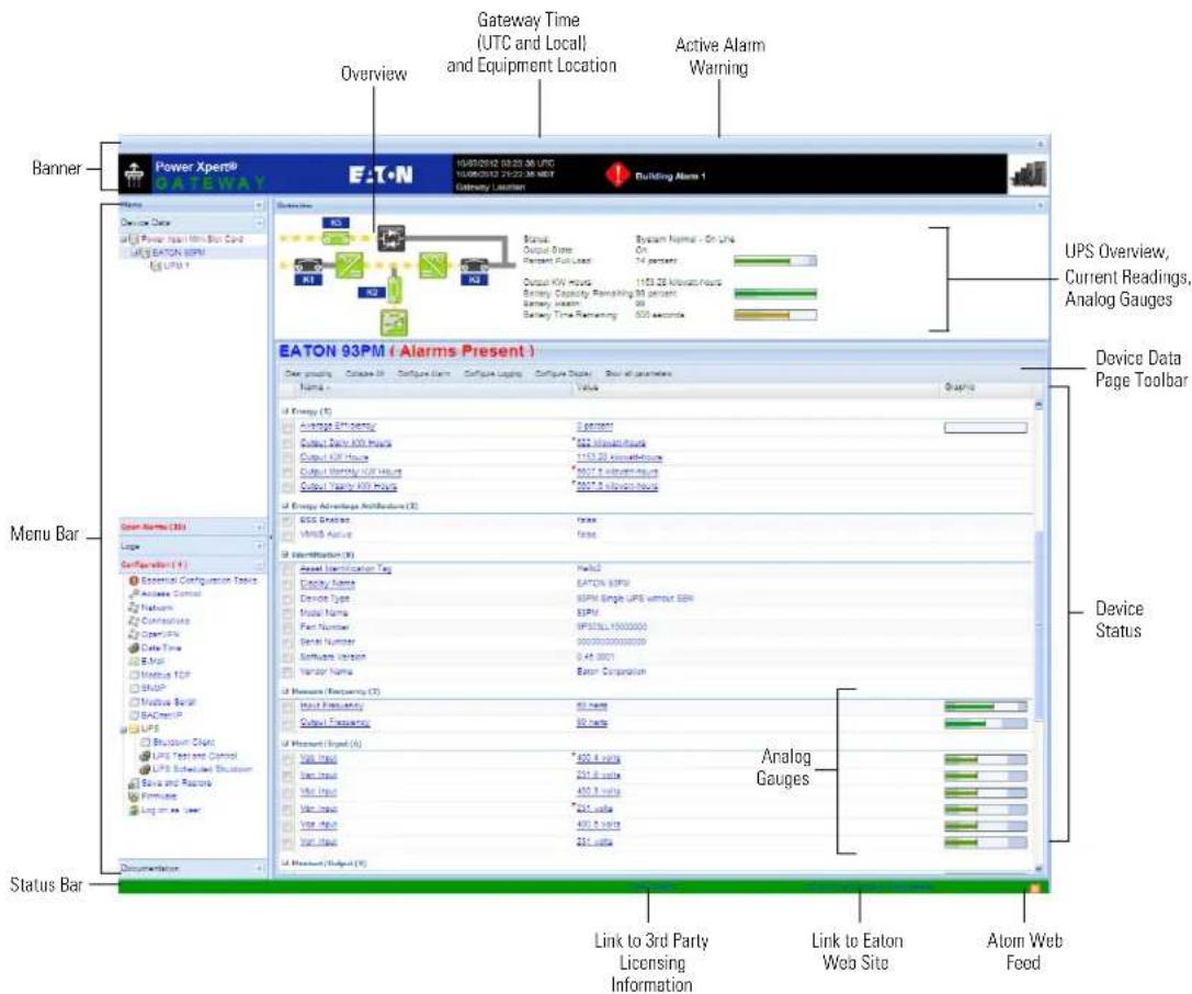
Figure 29. Navigating the Home Page
This interface provides typical windowing techniques such as re-sizing, scrolling, expanding/collapsing, and hover-over on text to see additional information.
Areas and features of the card's home page:
- Banner. The page banner displays the gateway time in UTC (Coordinated Universal Time). The local time and system location can be configured to also display in the banner.
If there is an active alarm in the hardware, a flashing alarm icon with an alarm message displays in the banner. Click the alarm message in the banner to display the Open Alarms page.
The highest level of an alarm active in the UPS displays as follows:
- Red for critical
- Yellow for caution
- Blue for acknowledged, but not closed (still alarming)
NOTE An active alarm is different from an open alarm:
- Active Alarm. An alarm is active when an alarming condition exists in the UPS. Messages display on the UPS LCD panel and on the card interface banner when alarms go active and disappear when the alarming condition clears.
- Open Alarm. When an alarm goes active, it is also considered open and remains open (even after the condition clears in the UPS hardware) until it is closed by an operator. Operators are required to close alarms to ensure they are seen. While the UPS LCD panel and the card interface banner display the alarms that are active in the UPS, other areas of the card interface, (such as the Open Alarms page, device data pages, and the alarm log), display any alarms that have not been closed by the operator. Since closing an alarm that is still active in the hardware quickly results in the generation of a new alarm, an operator has the option to mark an alarm as acknowledged to indicate it has been seen.
To close or acknowledge an open alarm, see "Alarm Notices" on page 42.
- Menu Bar. The menu bar contains links to additional pages for status information and configuration options. Menus are expandable and collapsible. The Device Data menu is expanded when you first log on. If an alarm is active, the Open Alarms menu category turns red and the number of open alarms displays in parentheses, so that alarms are never hidden even if the menu is collapsed. Use the menu bar to move through the card's Web pages.
-
Analog Gauges. Analog gauges display on the Overview and Device Data pages next to metered items to show related critical device information, such as status, power, and energy levels at a glance. Examples of metered items are:
-
Percent full load
- Percent battery left
- Bypass, input, and output frequency
- Battery time remaining
- Power output
- Remote humidity and temperature (if the optional EMP is connected to the card)
The bar is green for the normal operating range (white background) and gradually changes to yellow and then red as it moves to the caution range (light blue background) to critical (darker blue background).
Pause the pointer over the information icon to display numerical limits.
-
Overview. The Overview displays a functional status diagram of the UPS (or UPSs in a parallel system). The animated yellow line shows the direction of the energy flow. To the right of the diagram, a list of the most relevant current readings displays. The List tab page displays a complete list of current readings.
• Device Data Page Toolbar. -
Group by Category / Clear Grouping - toggles whether the parameters are grouped by category or listed alphabetically
- Collapse All / Expand All - toggles all categories and sub-categories
- Configure Alarms - edit the selected alarm attributes, such as enable the alarm, auto close, alarm priority (severity), and custom alarm message
- Configure Logging - configures whether parameter changes generate a notification message or are logged either as they occur or at intervals
- Configure Display - configure how a selected parameter is displayed
- Show Summary Parameters / Show All Parameters - displays essential data most often used to determine the overall status of the device.

NOTE The Output KW Hours displays on the Overview and also on the Device and List tabbed pages. Because the Output KW Hours is reset to zero when the card is restarted, Eaton recommends that this feature not be used for billing purposes. If you choose to use this value for billing purposes, record the Output KW Hours before restarting the card.
- Atom Web Feed. The card supports Atom Syndication Format (Atom) for Web feeds. The orange Atom icon is in the status bar. Click the Atom Feed icon to view new content or subscribe to the PXGMS UPS Card feed data. Some browsers also display the Atom Feed icon in the address bar.
- 3rd Party Licensing Link. The 3rd Party Licensing link in the status bar directs you to a list of all licenses used with the PXGMS UPS Card. Each listing links to the full license text.
- Link to Eaton Web Site. Quick link to Eaton Power Xpert Architecture Web page.
Identifying Monitored Equipment
The Device Data section of the menu lists the monitored equipment, such as PXGMS UPS Card, UPS, or optional EPM. Each equipment page has a Device Data Page Toolbar (see Figure 29 on page 22). The selected button determines how the page displays detailed information related to the equipment. You can choose the information you want to display and whether you want items organized by category with headings displayed, or all items in alphabetical order. You can also select to display additional columns from the Graph heading drop down list.
You can also initiate additional operations on the Device Data parameters that are underlined on the display page, such as:
- Edit display names and asset tags
- Generate and display trend graphs
• View interval logs

NOTE The configurable values may also be available on other pages, such as the System Location field on the Network Configuration page. Changes made to these fields are updated everywhere they appear.
Configurable fields for the PXGMS UPS Card are:
- Display Name
- Asset Identification Tag
Configurable fields for the UPS are:
• Asset Identification Tag - ID group
• Display Name - ID group - Attached Devices
• Battery Last Replaced Date - Date Last Serviced
- Installation Date
- Low Runtime Alarm Setpoint (An alarm is sent indicating the time remaining before the battery is depleted. Increasing the time allows for additional time to shut down a system before the battery is depleted.)

NOTE
See "Configuring Automatic Shutdown of UPS-Protected Computers" on page 34 for information on power outage notification and configuring the shutdown process for registered IPP clients.
The configurable field for load segments is Display Name
Configurable fields for the EMP are:
• Asset Identification Tag
- Display Name
Device Data Page Operations
The Device Data parameters that are underlined on the display page have associated operations that can be launched by clicking on the parameter. To see what operation is available, mouse over the parameter and the available operation will be shown (see Figure 30).
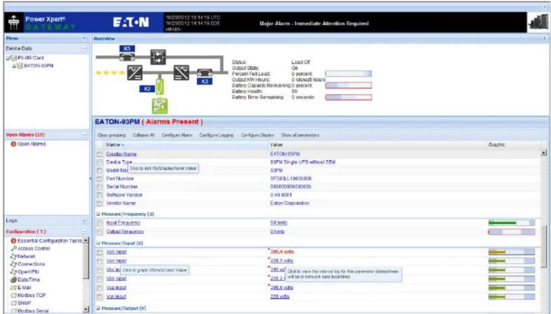
Figure 30. Device Data Parameters Rollover

NOTE
Graphs can be generated for measures, anything that is interval logged, or anything that is alarm enabled.
To edit a Device Data parameter:
- Click the Device Data parameter, such as Asset Identification Tag and the Edit Value window will open (see Figure 31).
- Enter the device information and click Save.
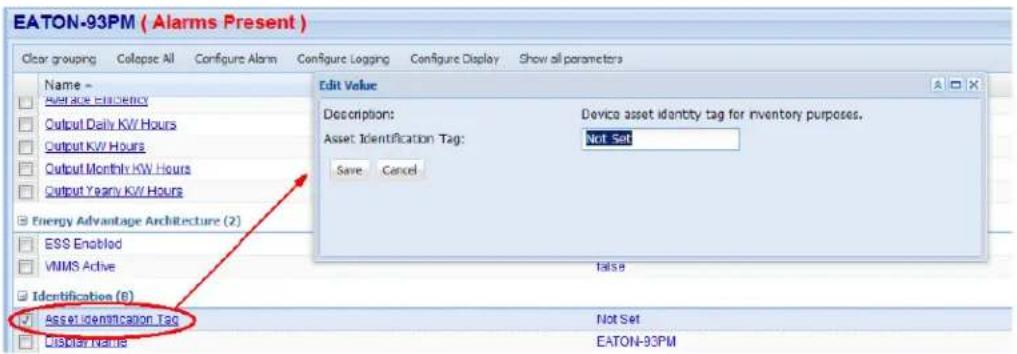
Figure 31. Edit Device Data
To view an interval log of the device data parameter:
- Click the Device Data > Value parameter (see Figure 30). The File Download window opens.
- Click Save and specify the location to save the file to.
- Open the file using Microsoft Excel to view the interval log.
To generate a customized trend log graph:
- Click the Device Data > Measure parameter (see Figure 30). A "Build Chart ..." message opens and displays chart progress information until completion.
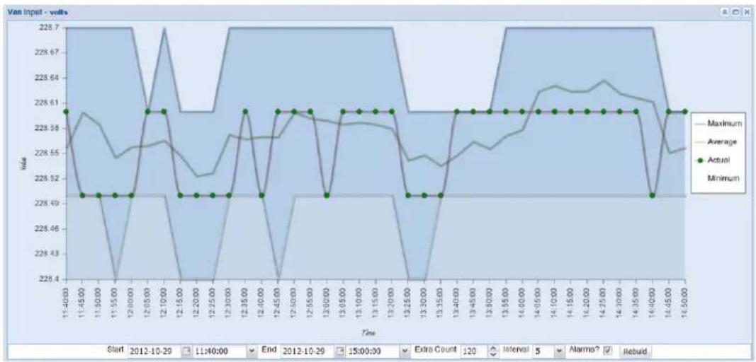
Figure 32. Trend Log Chart

NOTE
There is hover text for each point on the graphs. This is particularly informative for alarm points.
-
To customize the chart, use the Start, End, Extra Count, Interval or Alarms fields at the bottom of the display to change the data set (see Figure 32).
-
If any of the customize parameters were changed, click Rebuild to rebuild the chart with the new parameters.

NOTE
When using Internet Explorer 8, alarms are sometimes not graphed correctly on top of interval log data. Other browsers such as Mozilla Firefox and Google Chrome are unaffected by this.
Configuring Tasks Essential to Initial Configuration
The Essential Configuration Tasks page provides a summary of important tasks relating to the card's initial setup and configuration. If essential tasks have not been configured, the Configuration category on the menu bar displays in red along with the number of unconfigured essential tasks. Other unconfigured tasks display in blue on the Essential Configuration Tasks page.
To configure essential tasks:
- Select Essential Configuration Tasks from the Configuration menu.
The Essential Configuration page displays. Unconfigured tasks have links to the associated configuration page. Configured tasks are identified as "Ok."
-
Click the link for the task you want to configure. The associated configuration page displays.
-
Complete the configuration and click Apply.

NOTE
Refer to the related procedure in this user's guide for detailed instructions on completing the task.
Changing the Passwords
The username and default password is user for read-only privileges. The username and default password is admin for configuration (read/write) options. The characters in the password fields appear as asterisks (*).
To change the passwords:
- Click Access Control from the Configuration menu.
The Access Control Configuration page displays with the password fields.
- To change the user password, enter the new password twice (replace existing asterisks) in the Password for the user account fields.
To change the admin password, log on as admin and enter the new password twice (replace existing asterisks) in the Password for the admin account fields.
-
Click Apply and then OK to save the settings. The logon prompt displays.
-
Log on to the card using the new password.

NOTE You must be logged on as admin to configure the card. To prevent unauthorized access after you finish configuring the card, close the browser.
Setting the Date and Time
The PXGMS UPS Card can be configured to synchronize the date and time with one or more NTP servers, or the date and time can be manually set. In addition, temperature unit of measure can be set to display as Fahrenheit or Celsius and the interface display language can be selected. Changes made to these fields are updated everywhere they appear.

NOTE
All date and time selections are automatically converted to Coordinated Universal Time (UTC).
To set the date and time, and temperature unit of measure:
- Select Date/Time from the Configuration menu.
The default is to synchronize the date and time from the PC clock.
- To synchronize the card with Network Time Protocol servers, select Synchronize with NTP server(s) and type the IP addresses or host names. You can synchronize the card with up to three NTP servers.
The NTP status message displays to the right of the Synchronize with NTP server(s) field as one of the following:
- Not running – Indicates that NTP is not running.
- Started, not synchronized – Indicates that NTP is running, but is not yet synchronized with an NTP server or controlling the local clock.
- Synchronizing with NTP server – Indicates that NTP has synchronized with the local clock, but is not yet synchronized with an NTP server.
- Synchronized to XX, NTP stratum YY – Indicates that the card is synchronized with an NTP server at IP address XX that is operating at NTP Stratum YY.

NOTE
When using host names, verify that the IP address of your network DNS Server is configured (see "Network Configuration" on page 19).

NOTE When NTP status is Synchronized and there is a large discrepancy between the PXGMS UPS Card time and the actual time, it may take 5–30 minutes for NTP to reset the card to the proper time.
- To set the time manually, select Set date/time manually and type or select the local date in mm/dd/yyyy format and the local time in hh/mm/ss format.
- To customize how the date displays in the card's data and event logs, select a Date format for logs option (mm/dd/yyyy, dd/mm/yyyy, yyyy-mm-dd, or ddmmm yyyy). The default is mm/dd/yyyy.
- To select the time zone for the card, specify the Time zone for logs, email, and connected device.
- To specify how the temperature displays on the Web page, select Fahrenheit (default) or Celsius.
- To change the interface display language, select a language from the Locale drop down list.
- Click Apply and then OK to save the settings.
- Refresh the Web page to view the updated formats.
Configuring SNMP Options
This section describes the following SNMP configuration options:
- Configuring community strings and trap recipients
- Changing SNMP access
- Setting system location and system contact
• Managing from an SNMP Network Management System (NMS)
Community Strings and Trap Recipients
The PXGMS UPS Card supports several event-related traps that can be reported to the SNMP network management software. See Chapter 6, "MIB Files" on page 59 for more information.
To configure the SNMP options:
- Select SNMP from the Configuration menu.
- SNMPv1 and SNMPv3 are supported and both versions are enabled by default. To modify, clear the check box for the version to be disabled. The fields associated with the disabled version become unavailable (dimmed).
- For SNMPv1 configuration, type a new community string in the appropriate field to change the community strings.
The default community strings are public for read-only, private for read-write. - For SNMPv3 configuration, enter a new read-only username and password and read-write username and password in the appropriate fields. Passwords for SNMPv3 must be at least 8 characters long.
- To modify the Trap recipient community string field, type a new name. The default is "public".
- Click Add to add a new trap recipient entry to the list. The Recipient field populates with the next available number.
- Enter the trap recipient IP address or host name in the IP/hostname field.

NOTE
When using host names, verify that the IP address of your network DNS Server is configured ("Network Configuration" on page 19).
- Click Apply and then OK to save the settings.

NOTE
Select the Recipient drop-down menu to view all assigned trap recipients.
-
Repeat Steps 6 through 8 for each additional trap recipient.
-
To remove a trap recipient:
a. Click Delete Last.
b. Click OK when prompted to remove the settings for the trap recipient entered last.
Changing SNMP Access
The default is to limit access to the card by trusted SNMP Network Management System hosts only.
To add a host to the Trusted Host List for restricted access:
- Select Access Control from the Configuration menu.
- Verify that the check box for SNMP access restricted by IP/hostname is selected.
- Type the trusted NMS host's IP addresses or host names, separated by a semicolon, in the Trusted IPs/hostnames field.

NOTE
When using host names, verify that the IP address of your network DNS Server is configured (see "Network Configuration" on page 19).
To allow access that is unrestricted by hostname (though still qualified by community names or SNMPv3 passwords):
- Select Access Control from the Configuration menu.
- Clear the check box for SNMP access restricted by IP/hostname.
- Click Apply and then OK to save the settings.
- Click Apply and then OK to save the settings.
System Location and System Contact
To set the system location and system contact:
- Select Network from the Configuration menu.
- Enter the physical location of the installed UPS/card in the System location field. This value also displays in the card's Web page banner.
- Enter the information to identify someone to contact with questions about this device in the System contact field. For example, you can type a person's name, phone number, department, e-mail address, physical location, or combination of these items, such as John Smith x123.
- Click Apply and then OK to save the settings.
Management from an SNMP NMS
To access the PXGMS UPS Card using SNMP:
- Verify that the NMS is configured for the correct community strings or SNMPv3 usernames and passwords, as shown on the SNMP Web page. See "Community Strings and Trap Recipients" on page 29.
- Verify that the NMS is a Trusted Host, or that your PXGMS UPS Card is configured for unrestricted SNMP access on the Access Control Configuration Web page. See "Changing SNMP Access" on page 30.
- Select the MIB Files folder from the Documentation menu (or visit www.eaton.com/powerxpert) for the following MIB files for the PXGMS UPS Card:
MIB Name Filename Description
| Powerware UPS MIB | XUPS-MIB.txt | Meters and traps for Eaton UPSs |
| RFC 1628 UPS MIB | UPS-MIB.txt | Meters and traps for vendor-independent UPSs |
| Eaton EMP MIB | EATON-EMP-MIB.txt | Meters and settings for the EMP |
| Eaton Alarms+Traps MIB | EATON-PXG-MIB.txt | Alarms and notifications (traps) |
| Eaton Object Identifier (OID) assignments | EATON-OIDS.txt | Base document for all OID assignments for Eaton MIBs |
| RFC 4133 Entity MIB | ENTITY-MIB.txt | Identification and description of each device attached to the card |
| RFC 4268 Entity State MIB | ENTITY-STATE-MIB.txt | Five availability status meters for each device attached to the card |
| RFC 4268 Entity State MIB Part 2 | ENTITY-STATE-TC-MIB.txt | Possible state values for the Entity State MIB |
Add these files to the MIB database of your SNMP management software (such as HP OpenView™ and IBM® Systems Director).
- Use the facilities provided by the SNMP management software to access the individual MIB objects. See Chapter 6, "MIB Files" on page 59 for more information.
Configuring Modbus TCP/IP Options
To limit access to the card from trusted Modbus Transmission Control Protocol/Internet Protocol (TCP/IP) addresses only:
- Select Access Control from the Configuration menu.
- Select the Modbus TCP access restricted by IP/hostname check box.
- Type the trusted host's IP addresses or host names, separated by a semicolon, in the Trusted IPs/hostnames field.

NOTE When using host names, verify that the IP address of your network DNS Server is configured (see "Network Configuration" on page 19).
- Click Apply and then OK to save the settings.

NOTE For information on Modbus registers and return error codes, see "Modbus Registers for TCP and RTU" on page 65.
Configuring BACnet/IP
BACnet/IP communication provides read-only data from Building Automation Systems (BASs) so that the PXGMS UPS Card can be easily integrated in a BAS alongside other BACnet/IP capable devices.
- Select BACnet/IP from the configuration menu.
- The initial setup screen requires that you first set a Routed Network Number for the virtual BACnet network that the PXGMS UPS Card "hosts" for the UPS BACnet Device. The UPS device will appear as the Routed Devices on that virtual BACnet network. Each BACnet/IP network uses the Routed Network Number to identify it. Ask your BACnet or BAS administrator to assign a unique routed network number within the enterprise-wide BAC/IP network you wish to connect to. Accepted values are 1 to 65534.
- Click Apply and then OK to save the settings.
- Wait 10 to 30 seconds and then click Discard. The automatic settings that depend on the routed network number are filled in.

NOTE
Descriptions of the BACnet/IP Devices provided by this PXGMS UPS Card can be downloaded from the card as EPICS files (see "Download BACnet/IP EPICS File" on page 33)
Editing BACnet IP Settings
The BACnet/IP data display has 3 configuration categories, Identification (Network card sub-category), BBMD and Virtual Routing (Routed Device Settings sub-category). Expand the categories and sub-categories to edit the automatic settings.
Identification section:
- Base ID for auto-assign - This value is automatically generated during initial setup. Edit this value to establish a good base for the range of BACnet IDs for your devices.
- Auto-assign network card ID - If there is a check-mark in this box, the Network Card > Device ID (object-identifier) cannot be modified. If this box is not checked, the Network Card > Device ID (object-identifier) can be modified.
- Device ID (object-identifier) - An initial value is automatically generated by the PXGMS UPS Card. If Auto-Assign Network Card ID is not enabled, you can edit this value if desired (it must be unique within the enterprise-wide BACnet network).
- Device object-name - An initial value is automatically generated by the PXGMS UPS Card. Edit this value if desired for a specific application (it must be unique within the enterprise-wide BACnet network).
- BACnet/IP MAC address - This value is automatically generated by the PXGMS UPS Card and cannot be modified.
BBMD section:
- IPv4 IP address for foreign registration - If you are using a BACnet Broadcast Management Device (BBMD) to connect the PXGMS UPS Card to a subnet, you must define the BBMD IP address to register with the BBMD on the remote subnet.
- BBMD time to live (seconds) - You can set the BBMD time to live value. The default is 360 seconds and you can set any value (in seconds) from 30 to 65536.
Virtual Routing section:
- Routed network number - The integer BACnet Network number assigned to the Virtual Network that "holds" the Routed Devices managed by this PXGMS UPS Card. This BACnet Network Number must be unique with the enterprise-wide collection of BACnet networks. Since no initial value can be intuited by the PXGMS UPS Card, the Virtual Routed Devices do not appear to exist via BACnet/IP until a value has been set for this field.
- Auto-assign virtual device IDs - If there is a check-mark in this box the Routed Device Settings > Device ID (object-identifier) cannot be modified. If this box is not checked, the Routed Device Settings > Device ID (object-identifier) can be modified.
- MAC template for Virtual Devices - This value is used as a template in generating the separate BACnet/IP MAC address of the routed BACnet/IP devices.
- Select the device - Select the appropriate device from the drop-down menu.
- Device ID (object-identifier) - An initial value is automatically generated by the PXGMS UPS Card for each Routed Device. If Auto-Assign Virtual Device IDs is not enabled, you can edit these values if desired (each device ID must be unique within the enterprise-wide BACnet network).
- Device object-name - An initial value is automatically generated by the PXGMS UPS Card for each Routed Device. Edit these values if desired for a specific application (each must be unique within the enterprise-wide BACnet network).
Configuring BACnet/IP Options
To limit access to the card by trusted BACnet/IP peers (BAS workstations or devices) only:
- Select Access Control from the Configuration menu.
- Select the BACnet/IP access restricted by IP/hostname check box.
- Type the trusted host's IP addresses or host names, separated by a semicolon, in the Trusted IPs/hostnames field.

NOTE
When using host names, verify that the IP address of your network DNS Server is configured (see "Network Configuration" on page 19).
4. Click Apply and then OK to save the settings.
Download BACnet/IP EPICS File
An electronic protocol implementation conformance statement (EPICS) file provides verification that devices meet BACnet standards for objects and services. In the PXGMS UPS Card, an EPICS file is available for any device selected in the Device Data section of the menu bar.
The file is in text protocol information (.TPI) format and is machine and human readable. This allows EPICS files to provide data to software test programs and for system configuration at the BAS.
To download and save an EPICS file:
- Expand the Documentation section of the Menu Bar and select BACnet/IP EPICS Files. The BACnet/IP EPICS File overview page opens.
- Select the check box of the Display Name for the desired device EPICS file.
- The Show Value option is selected by default and will add current value information to object fields.
- Click View EPICS File to generate the .TPI file.
-
The File Download window opens providing the options to Open, Save, or Cancel the file.
-
Click Save and specify where to save the .TPI file.
To view the EPICS file, open it with any text reader such as Notepad.
Configuring HTTP and HTTPS
To configure the ports for Hypertext Transfer Protocol (HTTP) and HTTP over Secure Socket Layer (HTTPS):
- Select Access Control from the Configuration menu.
- Type the TCP port number for HTTP in the HT TP port field (the default is 80).
- Type the TCP port number for HTTPS in the HT TPS port field (the default is 443).
- To require a secure connection to the card, select the Require HTTPS check box.
- Click Apply and the n OK to save the settings.
Configuring Automatic Shutdown of UPS-Protected Computers
Shutdown Client software supports remote UPS monitoring and automatic shutdown of the computer systems connected to the UPS. Intelligent Power Manager (IPM) and Intelligent Power Protector (IPP) are shutdown client software applications available from www.eaton.com/pxgms under Software Downloads.

NOTE Refer to the shutdown client User Guide that you are using for configuration information of the application software.
Configuring Shutdowns for a UPS
Settings found in the Configuration page are related to the automatic shutdown of the UPS connected to the protected computer system.
To configure the UPS actions as a result of a client shutdown:
- Expand the UPS folder on the Configuration menu and select Shutdown Client.
- Setup a unique Username and Password for authenticating the shutdown clients.

NOTE The default setting is admin for username and password.
- To turn off power to the UPS output receptacles following the client shutdown:
a. Select the UPS to turn off following OS Shutdown check box.
If the this check box is not selected, the power remains available to the UPS output receptacles until the UPS battery power is exhausted.
b. Set the appropriate number of seconds for the Mi nimum delay before output shutdown sequence begins to ensure that any shutdown client and their respective operating systems have enough time to complete their shutdown before the UPS turns off. Set this value as appropriate for your system and available battery runtime and understand that the needs of individual shutdown clients may extend the delay automatically to ensure their complete shutdown. To modify, enter a value between 30 and 3600 seconds (30 seconds to 1 hour).
- To restart the UPS and the associated load:
a. Select the UPS to restart following the return of AC line check box.
If this check box is not selected, the UPS remains off (requiring local interaction to turn it back on) when utility power returns.
b. Set the time for Delay before output restart to a valid delay value to allow the UPS enough time to restart after the specified delay. To modify, enter a value between 10 and 3600 seconds (10 seconds to 1 hour).
- Click Apply and then OK to save the settings.
Shutdown Clients
The Registered Shutdown Clients area displays the IP Address, Application Name, Shutdown Timer and Shutdown Duration of the clients that have registered for the shutdown service.

NOTE
Shutdown clients such as IPM/IPP are only able to discover this card through Range scanning or Address scanning.
Managing UPS Power
The PXGMS UPS Card supports the ability to remotely turn off the UPS and its supported load. You can also reboot the UPS (cycling output power off and then back on) and schedule shutdowns and startups on a predetermined basis.

NOTE
Buttons on the UPS Test and Control page are not available (dimmed) if the UPS does not support that function.
Turning the UPS Load On and Off
To turn the UPS load on and off:
-
Expand the UPS folder on the Configuration menu and select UPS Test and Control. The UPS Test and Control page displays.
-
Select the Enable auto-refresh of UPS state check box if it is not already selected to view changes in the UPS load state as they happen.
-
Click Shutdown Now to shut down the selected UPS load. Results display to the right of the button.
-
Click OK to close the dialog box. The highlighted text reflects the UPS output state.

NOTE Shutdown clients are also shut down, so the shutdowns may be delayed to accommodate the OS shutdown times specified by the clients configuration.
-
Click Startup Now to start the selected UPS load. Results display to the right of the button.
-
Click OK to close the dialog box. The highlighted text reflects the UPS output state.
Scheduling a UPS Shutdown and Restart
Up to seven UPS shutdown and restart events can be scheduled for any time and day of the week.

NOTE 1 Times and dates for scheduled shutdowns and restarts are based on the local time and date configured for the card. The date and time is displayed in the banner. For more information, see "Setting the Date and Time" on page 28.
NOTE 2 Shutdown clients are also shut down, so the shutdowns may be delayed to accommodate the OS shutdown times specified on the client configuration.
To configure scheduled UPS shutdowns:
-
Expand the UPS folder on the Configuration menu and select UPS Schedule Shutdown.
-
Select the day, hour, and minutes for the shutdown and restart.

NOTE Do not overlap the scheduled shutdown and restart events. This will generate an Error Message.
-
Repeat Step 2 for each event to be scheduled.
-
Click Apply and then OK to save the settings.
If any of the scheduled shutdown times are not possible, an error message displays on the right.
-
To disable scheduled events, you can deselect one event or select the Disable all schedules check box. The event fields dim but the values remain for use later.
-
Click Apply and then OK to save the settings.
Configuring E-Mail Notification
You can use the PXGMS UPS Card to inform selected e-mail accounts of events and changes in status as they occur in the UPS or to provide a status message at a predetermined time.
To configure e-mail notification:
-
In the Configuration menu select E-Mail.
-
Enter the IP address or host name of the SMTP Server IP/hostname (mail server) that will be used to send the e-mail messages.
-
If you need to enter a username and password for the SMTP server:
a. Click Advanced SMTP configuration.
If you have made changes to the E-Mail page, a confirmation box opens. Click OK to save the settings; otherwise, click Cancel. The Advanced SMTP Configuration page displays.
b. Enter the username and password in the SMTP username and SMTP password fields.
c. Specify a "from" e-mail address in the SMTP From address field (for example, UPS_1@10.222.10.111).
d. Click Apply and OK to save the settings and return to the E-Mail page.
- Click Test SMTP server connection to test the configuration for the SMTP server. The SMTP Test Results window opens. Close the window when you finish viewing.

NOTE
If the SMTP test is successful, the confirmation displays immediately. A failed test response can take longer to display. Close the window if you want to terminate the test.
- Specify events to trigger an e-mail to be sent to all recipients:
a. In the Event triggers for all recipients field, click Configure to open the E-mail Event Trigger Configuration page.
b. Select specific event check boxes to indicate which events are to be included for e-mail notification or Select All. To clear all selections, click De-select All.
c. Click Apply and OK to save the settings. The E-Mail page opens.
- To test the event e-mail function:
a. In the Event triggers for all recipients field, click Configure to open the E-mail Event Trigger Configuration page.
b. Click Test Event E-Mail. A sample e-mail is sent for the first trigger event that is selected and saved.
c. In the Configuration menu, select E-Mail to return to the E-Mail page.
- To create a new recipient:
a. Select an unassigned number from the Recipients list.
b. Enter the recipient's e-mail address in the To field.
c. Click Apply. The e-mail address is added to the Recipients list.

NOTE
Up to ten recipients can be configured to receive event e-mail messages.
- To modify the options for a recipient, select the e-mail address from the Recipient list. In the Recipient Settings section, select or deselect the option check boxes. See Table 1 for a description of options.
Table 1. E-mail Options for Receiving Event Notification
Option Description
| Send on event active Sends an e-mail message when an event occurs | |
| Send on event clear | Sends an e-mail message when an event clears |
| Attach event log file to event emails | Attaches the event log to the event e-mail message (the log is always attached to status e-mail messages) |
| Attach interval log file to event emails | Attaches the interval log to the event e-mail message |
| Attach ID file to event emails | Attaches the identification files to the event e-mail message |
| Send periodic status emails | Sends periodic status e-mail messages |
| Days between periodic status emails | Sets the number of days between the periodic status e-mail messages |
| Time of day (gateway time) for periodic status email (HH:MM) | Sets the time of day for periodic status e-mail messages to be send (in 24-hour format, PXGMS UPS Card UTC time) |
- Click Apply and then OK to save the settings.

NOTE Apply changes before modifying or creating another e-mail recipient.
Configuring EMP Settings
The optional Environmental Monitoring Probe (EMP) allows remote monitoring of the UPS's environment through regular measurements of temperature and humidity through two external contacts.
The EMP is connected to the EMP port directly on the card with a standard Ethernet cable. Recognition is automatic. The Environmental Monitoring Probe selection is added to the Device Data and Configuration menus of the Web interface.
To configure the EMP settings:
- Select Environmental Monitoring Probe from the Configuration menu.
- For Contact #1 and #2, enter the Contact Description, such as External Contact #1 and External Contact #2.
- For Contact #1 and #2, select the Contact Type as Normally Open or Normally Closed from the pull-down menu (disabled is the default).

NOTE The shutdown clients shut down according to the parameters configured on the clients configuration page.
- If Contact #1 or Contact #2 alarms remain active for a specified amount of time, you can signal the shutdown clients to initiate a shut down. To specify the amount of time, set the seconds for Contact #1 and #2 in the Shutdown Delay field. Enter 1 to 600 seconds (1 second to 10 minutes) to enable the shutdown. The default is 0, which means the clients and UPS will not initiate shut down.
- To set the temperature alarm limits of the EMP, enter 32 to 158 degrees Fahrenheit (0 to 70 degrees Celsius) for the Temperature Upper Limit and the Temperature Lower Limit. The default for the upper limit is 158 and the default for the lower is 32.
- Use the Temperature Hysteresis to control the alarm when the current value is hovering around the limit. When the EMP temperature measure activates the alarm, it can come out of the alarm state only by dropping below the Temperature Hysteresis value. Enter a value between 0 and 10 percent. The default is 2 percent.
- If the temperature alarm remains active for a specified amount of time, you can signal the shutdown clients to initiate shut down. To specify the amount of time, set the seconds for the temperature alarm in the Shutdown Delay. Enter 1 to 600 seconds (1 second to 10 minutes) to enable the shutdown. The default is 0, which means the clients and UPS will not initiate shut down.
- To set the humidity limits of the EMP, enter 0 to 90 percent for the Humidity Upper Limit and the Humidity Lower Limit. The default for the upper limit is 90 and the default for the lower limit is 0.
-
Use the Humidity Hysteresis to control the alarm when the humidity percentage is hovering around the alarm limit. When the EMP humidity measure activates the alarm, it can come out of the alarm state only by dropping below the Humidity Hysteresis value. Enter a value between 0 and 20 percent.
-
If the humidity alarm remains active for a specified amount of time, you can signal the shutdown clients to initiate shut down. To specify the amount of time, set the seconds for the humidity alarm in the Shutdown Delay. Enter 1 to 600 seconds (1 second to 10 minutes) to enable the shutdown. The default is 0, which means the clients and UPS will not initiate shut down.
-
Click Apply and then OK to save the settings.
Saving and Restoring Configuration Settings
You can create a backup of the PXGMS UPS Card settings and restore them at a later date.
Creating a Backup
To create a backup:
- Select Save and Restore from the Configuration menu.
- To save the PXGMS UPS Card settings and preferences, click Save gateway configuration. The card exports an XML file containing the PXGMS UPS Card configuration settings.
- Click Save and enter a file name and location to save the XML file.

NOTE If a blank browser window remains open, close it.
Restoring a Backup

CAUTION
Restoring configuration settings overrides all changes made to the configuration settings since the backup file was created.
To restore the configuration settings from a backup file:
- Select Save and Restore from the Configuration menu.
- Click Browse to select the file name and then click Open.
- When prompted, confirm that you want to override the configuration settings with the backup file. Click OK or Cancel.

NOTE Update the Web page if the Device Data does not automatically display after the backup is complete.
Chapter 4 Operation and Maintenance
This section explains:
- Indicator descriptions
- DIP switch settings
- Open alarms
- Generating log files
- Firmware upgrade instructions
Figure 33 shows the PXGMS UPS Card front panel.
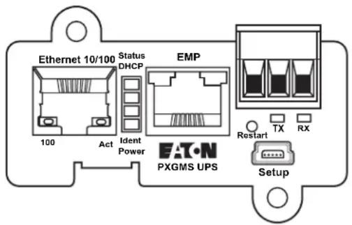
Figure 33. PXGMS UPS Card Panel
Indicator Descriptions
The Ethernet port indicator descriptions for the PXGMS UPS Card are listed in Table 2. The stacked indicator descriptions are listed in Table 3. The Modbus RTU (RS-485 port) indicator descriptions are listed in Table 4.
Table 2. Ethernet Port Indicators
| Indicator Label | Illuminated | Not Illuminated | |
| Ethernet 10/100 | 100 | Indicates a valid 100 Mb Connection (Link). | Indicates a valid 10 Mb Connection (Link) as long as the corresponding ACT indicator is illuminated. |
| ACT | Indicates network activity when the indicator is on or blinking. | Indicates no network activity. |
Table 3. Stacked Indicator Descriptions
| Label Color Illuminated Not Illuminated | |||
| Status | Green | Communication with the UPS has been established. | Communication with the UPS has not been established. As the card boots, the indicator remains off. However, if it remains off after two minutes, there is a communication problem between the card and the UPS. |
| DHCP | Amber | The PXGMS UPS Card is configured for DHCP and has obtained IP address information. | The use of DHCP has been disabled by the user, or PXGMS UPS Card has failed to obtain IP address information. |
| Ident Red A firmware update is in progress. Do not remove the card from the UPS. | A firmware update is not in progress. | ||
| Power | Green | DC power is available to the card from the UPS. | If all indicators are not illuminated, DC power is not available from the UPS. This may indicate that the UPS is off and unplugged. |

NOTE
During the power-on sequence, all four indicators illuminate briefly. Wait at least two minutes for the card's boot process to complete before comparing the indicators to the table above because indicators may turn on and off at different times in the boot process.
Table 4. Modbus RTU Indicator Descriptions
| Label Color Illuminated Not Illuminated | |||
| TX | Green | Data is being transmitted OUT of the card. | No data transmission to network |
| RX | Yellow | Card is receiving data IN. | No receive data from network |
DIP Switch Description
DIP switch definitions for the PXGMS UPS Card are listed in Table 5.
Table 5. DIP Switch Definitions
| S1 Position Number | OFF Position (Default) | ON Position |
| 1 | Enable previously stored network configuration settings (Normal mode) | Override the existing network settings and assign the local IP address using Zeroconf. Zeroconf will find the first available address starting at 169.254.1.1. So the assigned address would be 169.254.1.1, or 169.254.1.2, etc. - the first one that is not already being used by a device on the local subnet. |
| 2 | Reserved | Reserved. |
| 3 | Normal behavior | Reset the HTTP passwords to the defaults on boot (user and admin). After a successful boot, the switch should be turned back off before rebooting the card. |
| 4 | Reserved | Reserved. |
| 5 | Reserved | Reserved. |
| 6 | Normal behavior | Reset the card to factory defaults on boot (after a successful boot, the switch should be turned back off before rebooting the card again). |
Alarm Notices
Alarm notices display in three areas of the Web interface:
- Banner: If there is an active alarm present on the UPS (Condition Active: true), a flashing alarm icon and an alarm message will display in the banner. The alarm icon and message reflect the actual condition of the highest active alarm in the UPS. Clicking the alarm message displays the Open Alarms page.
- Device Data Summary and List page: If there is an open alarm, the “(Alarms Present)” message displays at the top of the Device Data page and the alarmed data value is highlighted in red text and will continue to be displayed in the alarm state until the alarm is closed.
- Menu bar: If there is an open alarm, "Open Alarms" and the number of active alarms display in red under the Alarms menu. Click Open Alarms to display the Open Alarms page.
NOTE An active alarm is different from an open alarm:

- Active Alarm. An alarm is active when an alarm condition exists in the UPS. Messages display on the UPS LCD panel and on the card interface banner when alarms go active and disappear when the alarming condition clears.
- Open Alarm. When an alarm goes active, it is also considered open and remains open (even after the condition clears in the UPS hardware) until it is closed by an operator. Operators are required to close alarms to ensure that they are aware that the alarm condition occurred. While the UPS LCD panel and the card interface banner display the alarms that are active in the UPS, other areas of the card interface (such as the Open Alarms page, device data pages, and the alarm log), display any alarms that have not been closed by the operator. Since closing an alarm that is still active in the hardware quickly results in the generation of a new alarm, an operator has the option to mark an alarm as acknowledged to indicate it has been seen.
The Open Alarms page displays a list of the latest alarms. Inactive alarms continue to display until they are closed.
To view, acknowledge, or close alarms:
- Select Open Alarms from the Open Alarms menu.
The Open Alarms page displays with the following information for each alarm:
• The alarm level (caution, critical, or major).
• Time and date when the error occurred.
• The parameter that is in alarm.
• The alarm message that displays on the UPS control panel (displays as a link).
- The condition of the alarm (active is true, inactive is false). The condition of the alarm indicates the actual condition of the UPS.
- To view the specific alarm parameter data, click the Alarm Message link. The Summary page displays and the value in error displays in red text.
- Select the alarm or alarms you want to acknowledge, discontinue acknowledgement, or close. Select the top checkbox to select all alarms, or select one or more alarms individually.

NOTE If the Alarm page updates, selections could be lost. Selecting an alarm row, or selecting Pause Auto-Update, prevents the page from automatically updating.
- Select one of the following:
a. Select Acknowledge Selected to acknowledge that you are aware of the alarm.
b. Select Un-Acknowledge Selected to reverse a previous acknowledgement.
c. Select Close Selected to close the alarm and remove it from the Open Alarms list.

NOTE 1 If a UPS alarm is still active in the UPS (Condition Active: true) and you close the alarm, a new alarm and event ID is entered into the Open Alarms list.
NOTE 2 If a UPS alarm clears automatically, close the alarm to remove it from the Open Alarms list.
- You have the option to add a note when prompted. Click OK to apply the selection.

NOTE This note is optional and is entered into the Event log and displays in the Power Xpert software. The note applies to all selected alarms.
- Click Continue Auto-Update to resume page updating.
Generating Log Files

NOTE 1 Data, Interval, Event, and System log files are comma-separated values (*.csv) files that can be opened using Microsoft Excel® software. Some computer configurations automatically open the files with the Microsoft Excel software instead of prompting you to save the file. Excel may default to a date format specific to the country the product is being used in, overriding the card specified format.
NOTE 2 The History and Battery Test logs are (*.txt) files in text format that can be opened by any text viewer software.
Data Log
The data log contains a history of the data value changes recorded by the gateway. To generate a data log:
- Select Data Log from the Logs menu.
-
To limit the number of records, type or select one or more of the following optional values:
a. Maximum number of records to return
b. Start Date
c. End Date -
Click View log.
-
Select a name and location for the file (if you chose to save the file when prompted).
Interval Log
The interval log contains a set of samples of data values taken at regular intervals by the gateway. To generate an interval log:
- Select Interval Log from the Logs menu.
- Select the name of the device.
- Select the interval (5, 15, or 60 minutes).
- To limit the number of records, type or select one or more of the following optional values:
a. Maximum number of records to return
b. Start Date
c. End Date
-
Click View log.
-
Select a name and location for the file (if you chose to save the file when prompted).
Event Log
The event log contains a history of the events recorded by the gateway. To generate an event log:
- Select Event Log from the Logs menu.
- To limit the number of records, enter one or more of the following optional values:
a. Maximum number of records to return
b. Start Date
c. End Date
-
Click View log.
-
Select a name and location for the file (if prompted to save).
System Log
The system log contains the history of the gateway administration activity. To generate a system log:
- Select System Log from the Logs menu.
- To limit the number of records, enter one or more of the following optional values:
a. Maximum number of records to return
b. Start Date
c. End Date
-
Click View log.
-
Select a name and location for the file (if prompted to save).
UPS History Log
The history log contains a record of internal UPS activity intended for use by service personnel to help diagnose UPS issues. To generate a history log:
- Select UPS Battery Test Log from the Logs menu.
- Click View log.
- Select a name and location for the file (if prompted to save).

NOTE
This file may be up 400K in size and may take several minutes to download from the UPS.
UPS Battery Test Log
The battery test log contains a record of UPS battery test activity. To generate a battery test log:
- Select UPS Battery Test Log from the Logs menu.
- Click View log.
- Select a name and location for the file (if prompted to save).

NOTE
This file may be up 400K in size and may take several minutes to download from the UPS.
Erasing a Log
To erase a data, interval, event, or system log:
- Click Erase log from the Data Log, Interval Log, Event Log, or System Log page.
- Click OK to erase the log; otherwise, click Cancel.
Upgrading the Card's Firmware
The card's firmware can be updated by downloading the appropriate file (pxgms_ups_x.x.x.x.rom) from www.eaton.com/pxgms. During the upgrade process, the PXGMS UPS Card does not monitor the UPS status.
To upgrade the firmware:
- Select Update Your Meter/Card firmware.
- Complete the Sign-In information and click Submit. The download an documentation screen displays.
- Click the firmware file link and click Save.
- In the Save As window, select the destination to download the file and click Save.

NOTE When saving the file, keep the default file name.
Chapter 5 Root Certificate Authority Installation
Improve the security of your Power Xpert Gateway Minislot (PXGMS) UPS Card on the Web by installing its root certificate authority (CA) into your browser's CA cache. A CA is a trusted third party that issues digital certificates for use with encrypted digital transactions. The digital certificate guarantees the identity of the Web site of the company that holds the certificate. In this case, the PXGMS UPS Card functions as both the CA and the certificate holder.
You can use the card without installing its root CA (using HTTP), but the transactions will not be as secure as with the root CA (using HTTPS). You can require secure transactions by configuring the card for HTTPS (see "Configuring HTTP and HTTPS" on page 34). The performance of the card is not impacted by using secure transactions.
This section explains root CA installation for:
• Windows Internet Explorer 7 and Internet Explorer 8
- Mozilla Firefox
- Google Chrome
Installing Root CA with Windows Internet Explorer 7 and Internet Explorer 8
To install a certificate for the PXGMS UPS Card with Windows Internet Explorer 7 or Internet Explorer 8:
- Open the browser and type the IP address of the card followed by the path /ca.html in the address bar. For example:
http://10.222.49.63/ca.html
The Root CA Installation page displays (see Figure 34).
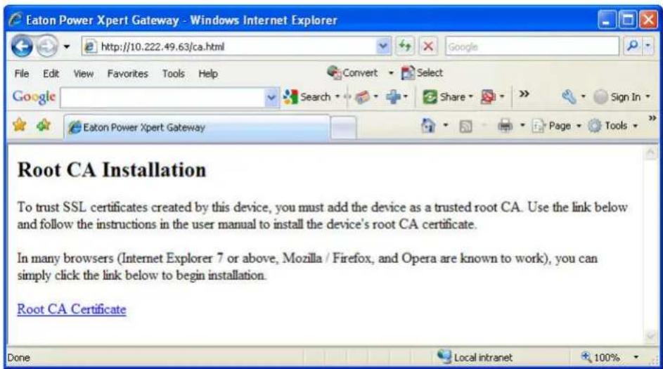
Figure 34. Internet Explorer – Root CA Installation Page
2. Click Root CA Certificate.
A File Download warning message displays (see Figure 35).
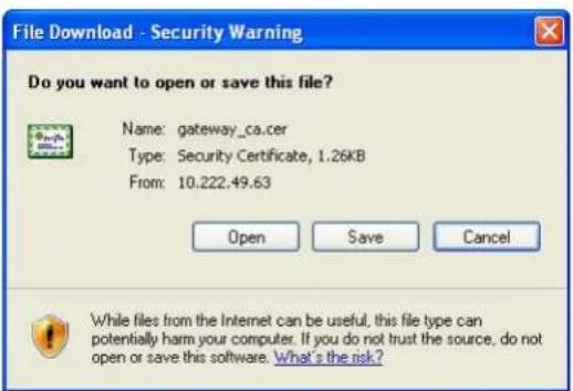
Figure 35. File Download Warning
3. Click Open.
The Certificate Window opens (see Figure 36).
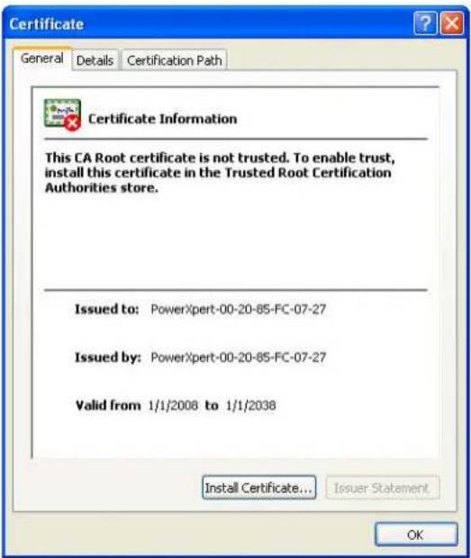
Figure 36. Certificate Window for the PXGMS UPS Card
4. Click Install Certificate.
The Certificate Import Wizard opens (see Figure 37).
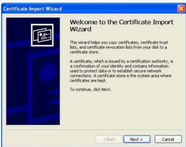
Figure 37. Certificate Import Wizard
5. Click Next.
The Certificate Store window opens, prompting you to specify a certificate store (see Figure 38).
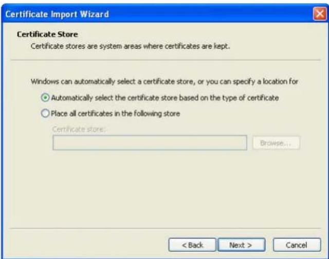
Figure 38. Certificate Store Window
-
Verify that the default setting, Automatically select the certificate store ..., is selected.
-
Click Next.
The Certificate Import Wizard displays a final verification (see Figure 39).
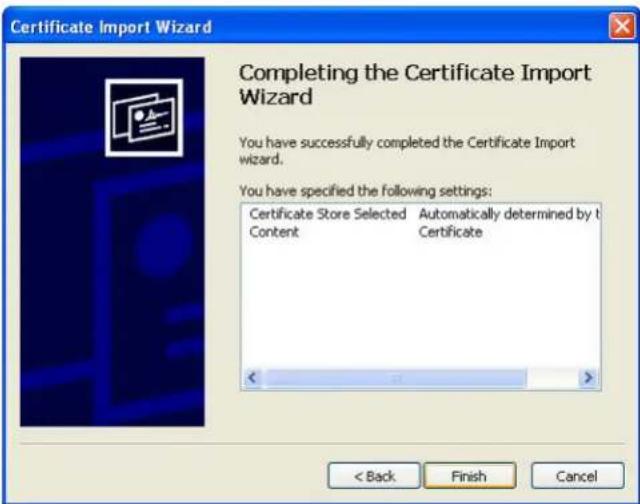
Figure 39. Verifying the Certificate Import Settings
- Click Finish to complete the wizard.
A message displays informing you that Windows will automatically trust any certificate issued by this CA (see Figure 40).
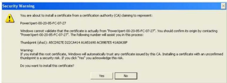
Figure 40. Security Warning Message
- Click Yes to install the CA.
A new message displays to verify that the import was successful.
-
Click OK to close the message.
-
Click OK to close the Certificate window.
-
The installation process is complete. You can now access the card using the HTTPS protocol. For example:
https://10.222.49.63
13. To view the certificate:
a. Select Internet Options from the Tools menu.
b. Click the Content tab.
c. Click Certificates.
d. Click the Trusted Root Certification Authorities tab, and then locate and select the certificate name on the list (see Figure 41).

NOTE The name of the certificate starts with "PowerXpert" followed by the MAC address of the card.
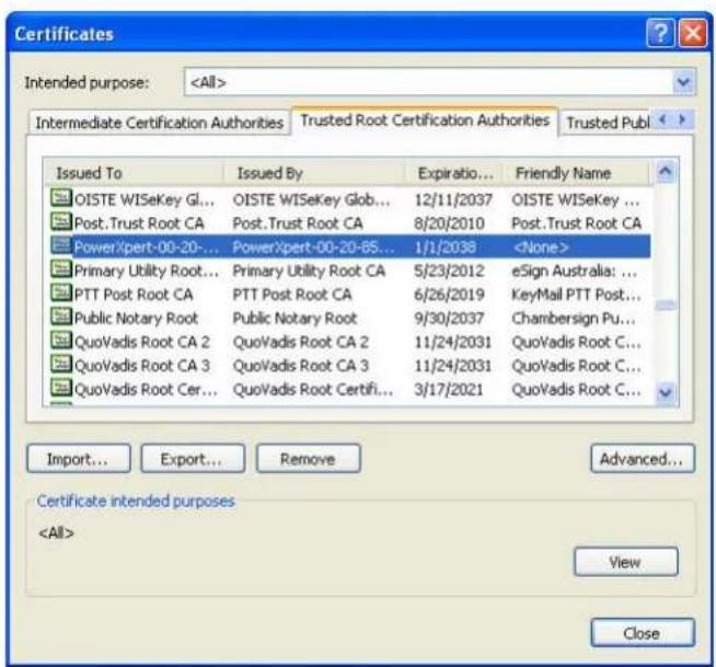
Figure 41. Trusted Root Certification Authorities Tab
e. Click View to open the Certificate window (see Figure 42).
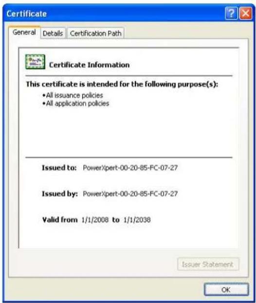
Figure 42. View Certificate Window
f. When you are finished viewing the information, click OK to close the Certificate window, click Close to close the Certificates window, and click OK to close the Internet Options window.
Installing Root CA with Mozilla Firefox
To install a certificate for the PXGMS UPS Card with Mozilla Firefox:
- Open the browser and type the IP address of the card followed by the path /ca.html in the address bar. For example:
http://10.222.49.63/ca.html
The following window opens (see Figure 43):
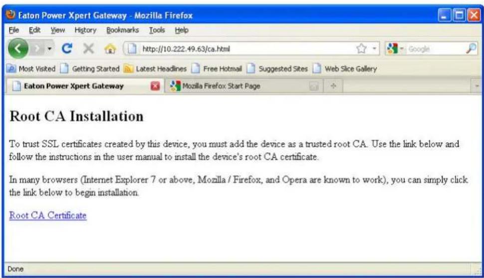
Figure 43. Mozilla Firefox – Root CA Installation Window
2. Click Root CA Certificate.
Firefox opens the Downloading Certificate window (see Figure 44).
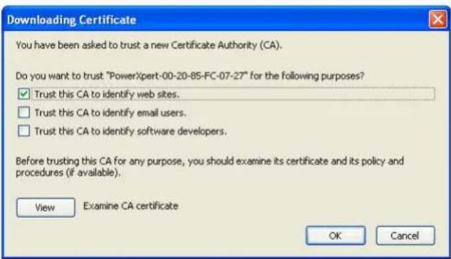
Figure 44. Downloading Certificate Window
- If desired, click View to manually examine the contents of the certificate.
- Select the Trust this CA to identify web sites check box.
- Click OK to complete the installation process.
The installation process is complete. You can now access the card using the HTTPS protocol. For example:
https://10.222.49.63
Installing Root CA with Google Chrome
To install a certificate for the PXGMS UPS Card with Google Chrome:
- Open the browser and type the IP address of the card followed by the path /ca.html in the address bar. For example:
http://10.222.49.63/ca.html
The following window opens (see Figure 45):
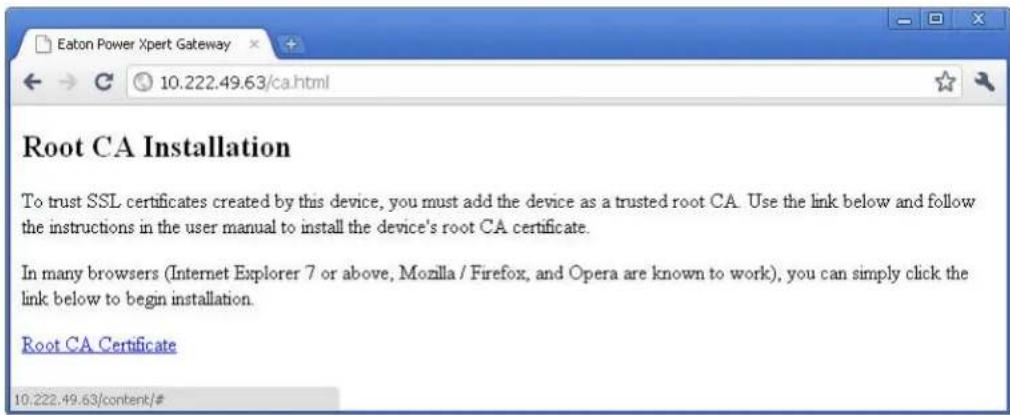
Figure 45. Google Chrome – Root CA Installation Window
- Click Root CA Certificate.
A File Download warning message displays at the bottom of the window (see Figure 46).
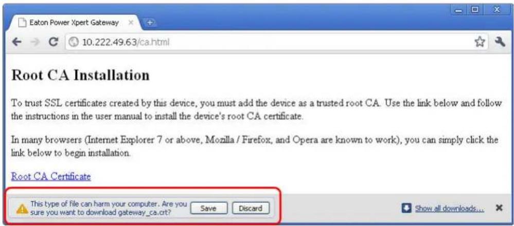
Figure 46. File Download Warning
3. Click Save.
The CRT (Security Certificate) file name displays at the bottom of the window (see Figure 47).
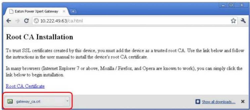
Figure 47. Security Certificate File
4. Click gateway\_ca.crt.
An Open File warning message displays (see Figure 48).
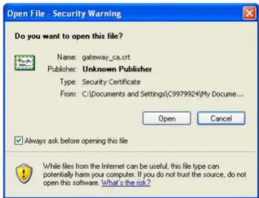
Figure 48. Open File Warning
5. Click Open.
The Certificate Window opens (see Figure 49).
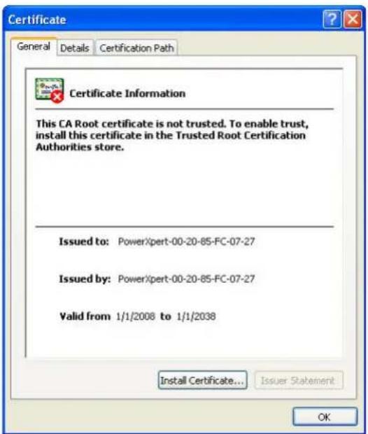
Figure 49. Certificate Window
6. Click Install Certificate.
The Certificate Import Wizard – Welcome window opens (see Figure 50).
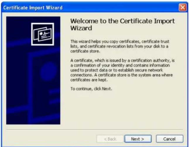
Figure 50. Certificate Import Wizard – Welcome Window
7. Click Next.
The Certificate Import Wizard – Certificate Store window opens, prompting you to specify a certificate store (see Figure 51).
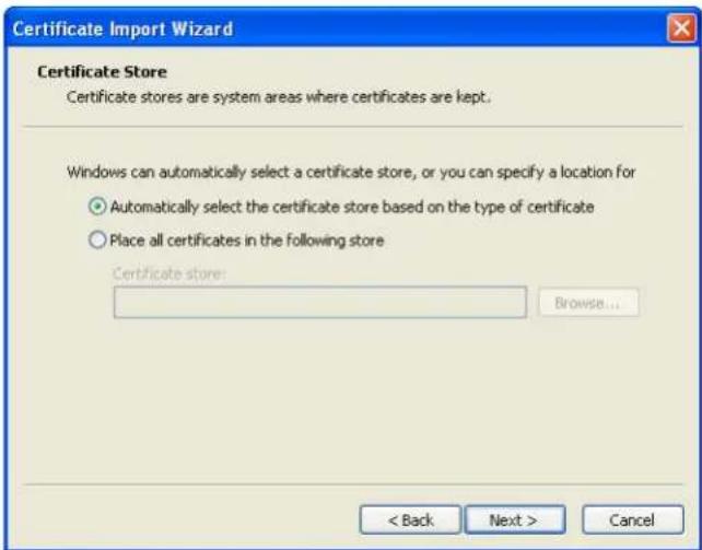
Figure 51. Certificate Import Wizard – Certificate Store Window
-
Verify that the default setting, Automatically select the certificate store ..., is selected.
-
Click Next.
The Certificate Import Wizard – Completing the Certificate Import Wizard window certificate displays a final verification (see Figure 52).
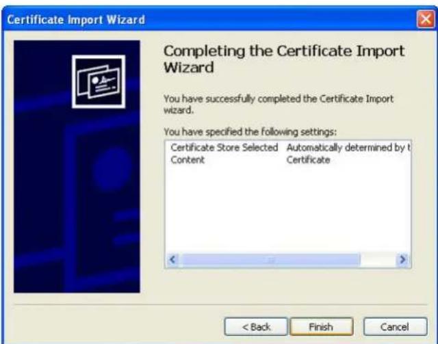
Figure 52. Certificate Import Wizard – Completing the Certificate Import Wizard Window
-
Click Finish to complete the wizard.
-
Click Yes to install the CA.
A new message displays to confirm that the import was successful.
-
Click OK to close the message.
-
Click OK to close the Certificate window.
The installation process is complete. You can now access the card using the HTTPS protocol. For example:
https://10.222.49.63
- To view the certificate:
a. On the Wrench menu, click Options, and then click the Under the Hood tab.
b. Scroll to the bottom of the window and click Manage Certificates.
c. Click the Trusted Root Certification Authorities tab and locate and select the certificate name on the list (see Figure 53).

NOTE The name of the certificate starts with "PowerXpert" followed by the MAC address of the card.
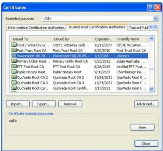
Figure 53. Certificates Window – Trusted Root Certification Authorities Tab
d. Click View to open the Certificate window (see Figure 54).
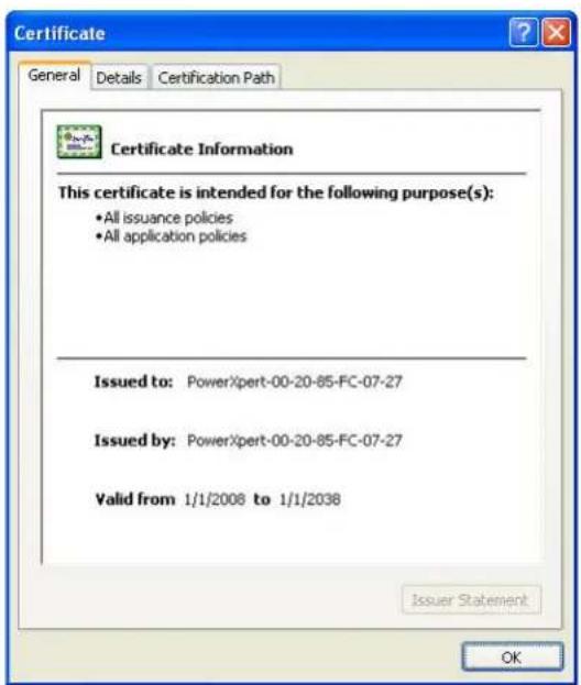
Figure 54. Certificate Window
e. When you are finished viewing the information, click OK to close the Certificate window, click Close to close the Certificates window, and click Close again to close the Google Chrome Options window.
Chapter 6 MIB Files
This chapter describes the Management Information Base (MIB) files available with the card. A MIB is an information repository residing on a device in a communication network. Network management software uses a device's MIB to manage the device. Every manageable device on a network has a MIB consisting of one or more files that list information about the device.
Use the facilities provided by your Simple Network Management Protocol (SNMP) management software to access the individual MIB objects. The objects define the information available about your UPS.
You can configure a device so that it generates a trap if a certain condition occurs, such as an alarm clearing. The trap is sent to the management station to inform it of the occurrence.
This chapter contains an overview of MIB definitions for each of the MIB files:
• Power ware UPS MIB
- RFC 1628 UPS MIB
- Eaton EMP MIB
- Eaton Alarms+Traps MIB
- Eaton OID Assignments
• RFC 4133 Entity MIB
• RFC 4268 Entity State MIB
• RFC 4268 Entity State MIB Part 2
See the MIB files for detailed information about each MIB object.
Selecting a UPS MIB File
You can use the Standard UPS MIB, as described in RFC-1628, or the proprietary Powerware UPS MIB with the client SNMP management software. Eaton recommends loading both MIBs. Table 6 lists the advantages of both MIBs.
Table 6. UPS MIB Comparison
| Standard UPS MIB | Powerware UPS MIB |
| Works with UPS SNMP agents from many vendors | Downward compatible with existing ConnectUPS cards or adapters |
| Includes some objects not found in Powerware UPS MIB: | Includes some objects not found in Standard UPS MIB: |
| upsBatteryStatus | Environment Group (xupsEnvironment) |
| upsConfigAudibleStatus | Receptacle Group (xupsRecep) |
| upsConfigInputFreq | Topology Group (xupsTopology) |
| upsConfigLowBattTime | xupsBatteryAbmStatus |
| upsConfigOutputVA | xupsBatteryLastReplacedDate |
| upsIdentAttachedDevices | xupsConfigInstallDate |
| upsIdentName | xupsControlToBypassDelay |
| upsSecondsOnBattery | xupsHeartbeatMinsInterval |
| xupsSendTrapType | |
| Enhances the Test and Control groups More trap types and trap descriptions | |
| Simpler battery test procedure | |
Powerware UPS MIB
NOTE Not every UPS model implements all of the Powerware UPS MIB objects. For example, the Bypass objects are supported only by larger UPSs with a separate bypass feed.
The Powerware UPS MIB consists of the following groups:
- Identification – the xupsldent status objects provide UPS information, such as the UPS model or UPS firmware version.
- Battery – the xupsBattery status objects provide UPS battery information, such as battery time remaining or the percentage of battery charge.
- Input, Output, and Bypass – the xupsInput, xupsOutput, and xupsBypass status objects allow the network manager to check or graph the condition of the UPS and its environment, such as monitoring input voltage and output load.
- Environment – the xupsEnvironment objects provide data around the UPS, such as the ambient temperature, and also allow you to set the upper and lower limits for the ambient temperature alarm.
- Alarms and Traps – the xupsAlarm and xupsTrapControl objects alert the SNMP management station to the condition of the UPS and of significant conditions, such as Shutdown Imminent.
- Test – the xupsTest objects perform a general UPS systems test and UPS battery test.
- Control – with the xupsControl objects, a network manager can remotely control the UPS by SNMP set commands, performing such tasks as shutting down or turning on the UPS.
- Configuration – the xupsConfig objects allow you to view UPS configuration, such as watts, voltage, or frequency and configure the UPS date and time and installation date.
- Receptacle – the xupsRecep objects provide status information about the controllable load groups and control objects for removing and returning power to these load groups.
- Topology – the xupsTopology objects describe the machine type and are primarily used for machine-to-machine communication within a power management system.
RFC 1628 UPS MIB
The RFC 1628 standard UPS MIB consists of the following groups:
- Identification – the upsIdent status objects provide UPS information, such as the UPS model or UPS firmware version.
- Battery – the upsBattery status objects provide UPS battery information, such as battery time remaining or the percentage of battery charge.
- Input, Output, and Bypass – the upsInput, upsOutput, and upsBypass status objects allow the network manager to check or graph the condition of the UPS and its environment, such as monitoring input voltage and output load.
- Alarms – the upsAlarm objects alert the SNMP management station to the condition of the UPS and of significant conditions, such as Shutdown Imminent; this group also lists well-known UPS alarm conditions.
- Test – the upsTest objects perform UPS diagnostic testing and provide the test results; this group also lists well-known UPS diagnostic tests.
- Control – with the upsControl objects, a network manager can remotely control the UPS by SNMP set commands, performing such tasks as shutting down or turning on the UPS.
- Configuration – the upsConfig objects allow you to view UPS configuration, such as watts, voltage, or frequency; for UPSs that allow read-write control for objects in this group, you can also remotely configure UPS parameters, such as input voltage or output frequency.
Eaton EMP MIB
Objects in this group are provided by the Environmental Monitoring Probe (EMP) and include temperature and humidity readings, alarming limits, the two contacts readings, and setup information. The group contains a table of values for environmental contact sensing (normally two digital inputs for monitoring all contacts).
Traps are sent in response to EMP changes to indicate the type of alarm, alarm acknowledgement, and alarm clearing.
Eaton Alarms+Traps MIB
Objects in this group provide a table of active alarms and a count of alarms currently active. The notification traps provided are triggered by the publishing of an alarm or event.
Eaton OID Assignments
These objects document all the object identifier assignments for Eaton products.
Entity MIB Files
The objects in these MIB files provide information standard in the industry:
- The RFC 4133 Entity MIB provides standard objects for identifying and describing devices attached to the card.
- The RFC 4268 Entity State MIB provides availability status measures for each device.
- The RFC 4268 Entity State MIB Part 2 provides possible state values for the Entity State MIB.
Selecting the UPS Trap Type
Use the Powerware UPS MIB xupsSendTrapType object to select the primary type of traps to be sent to the configured trapsinks when UPS alarms occur or clear. There are three types of traps: stnd(1), xups(2), and pxg(5). See Table 7 for trap comparison.
Table 7. UPS Trap Type Comparison
| xupsSendTrapType Options | stnd(1) | xups(2) | pxg(5) |
| MIB File that Sends Traps | RFC 1628 UPS MIB (UPS-MIB.txt) | Powerware UPS MIB (XUPS-MIB.txt) | Eaton Alarms+Traps MIB(EATON-PXG-MIB.txt) |
| Number of Defined Traps for Alarms and Notices | Only three:upsTrapOnBatteryupsTrapAlarmEntryAddedupsTrapAlarmEntryRemoved | Up to 50; each well-known Powerware UPS MIB alarm is mapped to a trap. | Eleven, with one trap sent for each entry in the PXGMS UPS Card Active Alarms table. Each trap indicates its severity level. |
| Advantages Simplest set of traps. | Breaks out the alarms into individual traps, and adds a text message describing the UPS alarm.Auto-clearing alarm types. | Comparable to other Eaton Power Xpert Gateway products and parallels the BACnet/WS events logged by the Power Xpert software.Fullest text description for each alarm.Includes traps when you acknowledge and close the alarms (see page42). | |
| Disadvantages You must decode the upsAlarmDescr object ID to determine which alarm has occurred. | None. | If five UPS alarms occur for an On Battery condition, it will send five traps.Alarm Cleared traps will not be sent until you acknowledge and close each alarm (seepage 42). | |
| Traps that are Sent Regardless of Trap Type Setting | upsTrapTestCompleted | xupstdCommunicationsLostxupstdCommEstablished | powerChainEvent(for example, StructureChanged events) |
Chapter 7 Modbus Remote Terminal Unit (RTU) Configuration
The Power Xpert Gateway Minislot (PXGMS) UPS Card is a network connectivity device for the UPS that also allows you to continuously and reliably monitor the UPSs in your Building Management System (BMS). The card supports the Modbus protocol to integrate data from the UPS into your building management system software.
The PXGMS UPS Card has the following Modbus related features:
• RS-485 communication through an isolated Modbus interface (see Figure 55)
• Supports Modbus READ INPUT STATUS and READ INPUT REGISTER commands
- Two-wire Communication topology
• LEDs showing communication activity
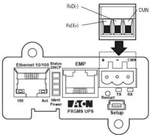
Figure 55. RS-485 Port
Wiring the PXGMS UPS Card RS-485 Port
The PXGMS UPS Card provides an easy path for integrating the UPS into an RS-485 Modbus network and also provides isolation of the communication between the UPS and the RS-485 Modbus network.
You will use the Modbus RTU interface connector to wire into the two-wire network.

NOTE The PXGMS UPS Card should be installed in the UPS prior to performing this procedure.
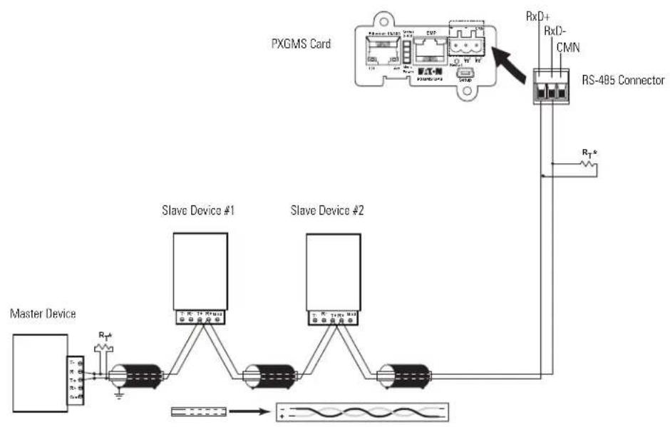
flowchart
graph TD
    A["Master Device"] -->|R_T*| B["Slave Device #1"]
    B --> C["Slave Device #2"]
    C --> D["RS-495 Connector"]
    D --> E["RxD+"]
    D --> F["RxD-"]
    D --> G["CMN"]
    style A fill:#f9f,stroke:#333
    style B fill:#ccf,stroke:#333
    style C fill:#ccf,stroke:#333
    style D fill:#cfc,stroke:#333
    style E fill:#fcc,stroke:#333
    style F fill:#fcc,stroke:#333
    style G fill:#fcc,stroke:#333
Figure 56. Two-wire RS-485 Modbus Network
NOTE 1 Belden 9841 or equivalent cabling (a single twisted-pair shielded cable with ground) is recommended.

NOTE 2 RT* - If the PXGMS UPS Card is the last device that is being attached to the RS-485 network, a 120 ohm resistor should be attached to the RxD+ and RxD- terminals of the 3-pin terminal plug (see Figure 56).
- Remove the detachable plug from the 3-pin terminal connector (see Figure 55 on page 62).
- Connect the RS-485 network signal TxD(+) to the RxD(+) plug connector (left connection).
- Connect the RS-485 Network signal TxD(-) to the RxD(-) plug connector (center connection).
- Re-seat the plug into the 3-pin terminal connector on the PXGMS UPS Card (see Figure 56).
Configure Modbus Serial Port and Mappings
- Expand the Mappings section of the Modbus Serial configuration data display area.
- Click the Add button.
- Set the Slave ID.
- Set the Device Name by selecting Power Expert Mini-Slot Card from the drop down menu.
- Select the Modbus Map from the drop down menu.
- Click Apply and OK.
Access to RTU Registers
See "Modbus Registers for TCP and RTU" on page 70 for information about accessing the Modbus registers.
Chapter 8 Modbus Registers for TCP and RTU
This chapter describes the UPS data that is available through the Modbus protocol. The UPS monitors several parameters, such as voltage, current, power, and alarms. The value of each parameter is stored in a corresponding Modbus data register.
The Power Xpert Gateway Minislot (PXGMS) UPS Card provides the ability to read the Modbus data registers using either Ethernet network by using Modbus TCP/IP building management programs or the Modbus RTU RS-485 serial interface to the building management system.

NOTE
If your Modbus program requires one-based addressing, add a one to the register addresses listed in Table 10 on page 69. For example, one-based addressing for the vendor name would be 1033 (1032 + 1). One-based addressing is the default setting for the PXGMS UPS Card.
Obtaining the Modbus Register Map
To view a list of the Modbus registers in your UPS:
- Select Modbus TCP Register Maps or Modbus Serial Register Maps from the Documentation menu.
- Select the hardware type from the Select a map to generate pull-down menu.
- Most Modbus TCP and Modbus Serial clients automatically decrement addresses by one before using them. If your client does not alter addresses in this way, clear the Use 1-based addressing check box.
- Click View Register Map. A dialog box opens.
- Click Open to view or Save to save the file.

NOTE The Modbus file is a comma-separated values (*.csv) file that can be opened in Microsoft Excel software. Some computer configurations automatically open the files in the Microsoft Excel software instead of prompting you to save the file.
- If you select Save, select a location for the pxgms-modbus-uid-XXX.csv file, where XXX is the UnitID of the requested map.

NOTE Some browsers leave a blank window open after you save or view the file. Close the window.
Returning Modbus TCP Error Codes
By default, the PXGMS UPS Card returns a Modbus error code when it receives an incoming register/discrete/coil READ request for an address that is not currently valid. To improve performance in some situations, you can configure the card to disable this error response and instead return zero-filled data in all of the invalid address ranges.
To change how error codes are returned:
- Select Modbus TCP from the configuration menu.
- Clear the Return (vs. zeros) error on unsupported read request check box to disable the error code or select the check box to enable the error code.
- Verify the Timeout setting.

NOTE
The timeout setting determines how long the PXGMS UPS Card will wait for a completed request message from the Master device.
- Click Apply and then OK to save the setting.
Returning Modbus Serial Error Codes
By default, the PXGMS UPS Card returns a Modbus error code when it receives an incoming register/discrete/coil READ request for an address that is not currently valid. To improve performance in some situations, you can configure the card to disable this error response and instead return zero-filled data in all of the invalid address ranges.
To change how error codes are returned:
- Select Modbus Serial from the configuration menu.
- Clear the Return (vs. zeros) error on unsupported read request check box to disable the error code or select the check box to enable the error code.
- Verify the Timeout setting.

NOTE
The timeout setting determines how long the PXGMS UPS Card will wait for a completed request message from the Master device.
- Set the proper Baud rate (default is 9600).
- Click Apply and then OK to save the setting.
Modbus Register Addressing
This section describes Modbus function codes, data formats, and data addressing.
Modbus Function Codes
The UPS registers are read using Modbus Function Codes (FC). For most UPS registers, FC 04 is used. For alarms, FC 02 is used. The UPS supports the following hex function codes:
Table 8. Function Codes
| FC Hex Description Use | |||
| 01 | 0x01 | Read Coil Status | Supported for compatibility purposes; returns the same data as FC 02 |
| 02 | 0x02 | Read Discrete Inputs | Single input data, such as alarms and discrete contacts |
| 03 | 0x03 | Read Holding Registers | Supported for compatibility purposes; returns the same data as FC 04 |
| 04 | 0x04 | Read Input Registers | Analog data (most string and numeric data types), such as voltage |
| 05 | 0x05 | Write Single Coil | For future use |
| 06 | 0x06 | Write Single Register | For future use |
| 15 | 0x0F | Write Multiple Coils | For future use |
| 16 | 0x10 | Write Multiple Registers | For future use |
Data Formats
Modbus programs usually provide an option for viewing various data types. Refer to your Modbus program documentation for detailed information on viewing data options.
A register is 16 bits (two bytes). The UPS supports the following data types:
- STRING – A string of ASCII characters (two per register). Consult the Size parameter to find the string's length for a given entry (it is a multiple of two so that entries are register-aligned).
- FLOAT – A 32-bit IEEE754 floating point number. FLOATs are always two registers.
- UINT – An unsigned integer. Consult the Size parameter to find the integer's size (in bytes) for a given entry (it is a multiple of two so that entries are register-aligned).
- INT – A signed integer. Consult the Size parameter to find the integer's size (in bytes) for a given entry (it is a multiple of two so that entries are register-aligned).
- TIME – The TIME type (ym dh ms) consists of six bytes specifying the year, month, day, hour, minutes, and seconds. The bytes are stored in hexadecimal format. If your Modbus application displays the individual bytes in a register, view the bytes using the decimal option. Otherwise, the bytes are best viewed by displaying the two-byte register in a binary format and translating each byte to decimal.
For example, if today is May 17, 2010 and the time is 10:45 and 20 seconds, viewing each byte in decimal would yield the following data, which is viewable as the year (10), month (05), day (17), hour (10), minutes (45), and seconds (20):
| 10 05 17 10 45 | 20 |
See "Time or Date (FC 04)" on page 70 for more information.
- BOOL – A binary (Boolean) value of 0 or 1. BOOL is usually assigned to discrete input alarms.
Data Addressing
If a data type spans multiple registers (such as a FLOAT), lower addressed registers map to higher-order parts of the value. Within each register, data is in most significant bit (MSB) first format.

NOTE 1 A Modbus register contains two bytes. Therefore, the number of registers containing the information can be obtained by dividing the bytes by two. For example, the vendor name in Table 10 on page 69 can be obtained by reading 32 Modbus registers starting at register 1032.
NOTE 2 If a register is not supported in a particular device, an exception response is returned.
UPS Modbus TCP Unit ID Numbers
The Unit IDs associated with the Modbus registers apply to specific UPS load groups or power modules (see Table 9).
The UPS has a Unit ID of 0, 1, 247, or 255, while UPS load groups or power modules within the UPS have Unit IDs that range from 2 to 127 and 239 to 243 (for UPS load groups or power module data). Some data is available at multiple Unit IDs as a work around for address limited Modbus software products.
If there is an optional Environmental Monitoring Probe (EMP) installed, use Unit ID 246, or 254 to obtain EMP data. See "EMP (FC 04)" on page 70 for more information.
Table 9. UPS Unit ID Numbers
| Unit ID Description |
| 0, 1, 247, 255 UPS Summary Data |
| 2–127, 239–243 UPS Load Group or Power Module Data |
| 244 NMC Modbus/JBus Card Compatible Data |
| 245, 253 Modbus Card Compatible Data |
| 246, 254 Environmental Monitoring Probe |
UPS Registers and Alarms
This section contains information for the UPS Registers (FC 04) and UPS Alarms (FC 02).
UPS Registers (FC 04)
Table 10 provides a partial list of data registers that are available from a UPS. Not all registers may be available in your UPS or in selected UPS load groups.
To read the vendor name in the UPS, set the Modbus program to Unit ID 1 and register 1032:
IP: <IP address of UPS>
Unit ID: 1
Starting Register: 1032
Number of registers: 32
Function Code: 04
The UPS returns 32 registers containing up to 64 characters. There are two ASCII characters per register, so the vendor name could be displayed as EATON.
To read the UPS output voltage from Phase C to Neutral, set the Modbus program to Unit ID 1 and register 4050:
IP: <IP address of UPS>
Unit ID: 1
Starting Register: 4050
Number of Registers: 2
Function Code: 04
The UPS returns a floating point value of the output voltage from Phase C to Neutral (such as 120.7 volts) of the UPS at the specified IP address.
Table 10. UPS Sample Registers (FC 04)
| Parameter Name | Display Name | Register | Discrete | Units | Data Type | Bytes |
| VendorName | Vendor Name | 1032 | No | No | STRING | 64 |
| ModelName | Model Name | 1064 | No | No | STRING | 64 |
| iDisplayName | Display Name | 1096 | No | No | STRING | 64 |
| iDeviceType | Device Type | 1128 | No | No | STRING | 64 |
| iDeviceID | Device ID | 1192 | No | No | STRING | 64 |
| SerialNumber | Serial Number | 1276 | No | No | STRING | 64 |
| SoftwareVersion | Software Version | 2108 | No | No | FLOAT | 4 |
| mACVoutC | Vcn Output | 4050 | No | Volts | FLOAT | 4 |
| mACVbypassA | Van Bypass | 4058 | No | Volts | FLOAT | 4 |
| mACVbypassB | Vbn Bypass | 4060 | No | Volts | FLOAT | 4 |
| mACVbypassC | Vcn Bypass | 4062 | No | Volts | FLOAT | 4 |
| mDCVbatt | Battery Voltage | 4377 | No | Volts | FLOAT | 4 |
| mAClinA | linA | 5022 | No | Amperes | FLOAT | 4 |
| mAClinB | linB | 5024 | No | Amperes | FLOAT | 4 |
| mAClinC | linC | 5026 | No | Amperes | FLOAT | 4 |
| mACloutA | loutA | 5028 | No | Amperes | FLOAT | 4 |
UPS Alarms (FC 02)
Table 11 provides a partial list of example UPS alarms. Your UPS may have different alarms. UPS alarms are not registers, but are discrete inputs and are read using FC 01 or FC 02.
The UPS monitors the condition of several parameters and can activate an alarm status if a parameter is out of range. For example, if the utility power is too high or too low, the UPS can set the Utility Out of Limits alarm.
To read the UPS On Battery alarm, set the Modbus program to Unit ID 1 and discrete address 1148:
IP:
Unit ID: 1
Starting Address: 1148
Number of Addresses: 1
Function Code: 02
The UPS returns a BOOL value (0 or 1), indicating if the alarm is active or not active. A return value of 0 (false) indicates an inactive alarm (the utility input is within limits). A return value of 1 (true) indicates an active alarm (the utility input is out of limits).
Table 11. UPS Sample Alarms (FC 02)
| Parameter Name | Display Name | Address | Discrete |
| aBuildingAlarm1 | Building Alarm 1 | 1019 | Yes |
| aOutputOverload | Output Overload | 1025 | Yes |
| aBatteryCheck | Check Battery | 1137 | Yes |
| aUPSOnBattery | UPS On Battery | 1148 | Yes |
| aBattDisconnected | Battery Disconnected | 1162 | Yes |
| aSystemNoticeActive | System Notice Active | 1185 | Yes |
| aSystemAlarmActive | System Alarm Active | 1186 | Yes |
| aUPMAlmMajorAlarm | Major Alarm | 3003 | Yes |
| aUPMAlmServiceRequired | Service Required | 3005 | Yes |
EMP (FC 04)

NOTE
See "Configuring EMP Settings" on page 38 for more information.
The optional EMP for the UPS can measure temperature and humidity. Because the device can be located outside the UPS, the reference is to auxiliary data. In addition, it contains two connections for monitoring the condition of auxiliary input contacts, such as a door switch. See Table 12 for a list of EMP registers.
An exception code is returned if the EMP is not installed.
To read the temperature at the UPS, set the Modbus program to Unit ID 254 and register address 12028:
IP: <IP address of UPS>
Unit ID: 254
Starting Register: 12028
Number of registers: 2
Function Code: 04
Table 12. EMP Registers (FC 04)
| Name Register Data Type Bytes | |||
| Vendor Name 1032 STRING 64 | |||
| Model Name 1064 STRING 64 | |||
| Display Name 1096 STRING 64 | |||
| External Contact #1 10248 UINT | 2 | ||
| External Contact #2 10249 UINT | 2 | ||
| Remote Temperature | 12028 | FLOAT | 4 |
| Remote Humidity | 12030 | FLOAT | 4 |
Time or Date (FC 04)
Some UPS models support a time and/or date function. This format has a DATE data type and contains six bytes. Each byte represents the year, month, day, hour, minutes, or seconds (see page 67 for more information).
To read the UPS date and time, set the Modbus program to Unit ID 1 and register 12203:
IP: <IP address of UPS>
Unit ID: 1
Starting Register: 12203
Number of registers: 3
Function Code: 04
The UPS would return three registers containing hexadecimal data in the ym dh ms format (for example, May 17, 2007 at 10:45 and 20 seconds).
| 07 05 | 11 0A | 2D 14 |
Viewing each byte in decimal would yield the following data, which is viewable as the year (07), month (05), day (17), hour (10), minutes (45), and seconds (20):
| 07 05 | 17 10 | 45 20 |
Viewing each byte as two-byte unsigned integers would yield the following data:
| 1797 4362 11540 |
Viewing each byte as binary would yield the following data:
| 00000111 | 00000101 | 0001 | 0001 | 00001010 | 00101101 | 00010100 |
Table 13. Time or Date Register (FC 04)
| Parameter Name | Display Name | Register | Discrete | Units | Data Type | Bytes |
| mCurrentTime | Time | 12203 | No | No | DATE | 6 |
Table 14. Technical Specifications
| CPU Freescale | TM MPC8313 |
| Memory | 128 MB RAM, 1 GB NAND Flash |
| Network Connections 10/100BaseT RJ-45 Ethernet port | |
| USB 1.0 device port (used for initial network connection through a standard RNDIS driver)RS-485 serial Modbus network port | |
| UPS Protocol | Eaton 93PM/PR series UPS communication protocol |
| Network Protocols (not limited to) | SNMP v1 or v3 over UDP/IPModbus TCP/IPModbus RTUHTTP/HTTPSBACnet/WSBACnet/IPNTPSMTPDHCPTCP/IP (including IPv4 and IPv6) |
| Supported SNMP MIBs | Powerware UPS MIBRFC 1628 UPS MIBEaton EMP MIBEaton Alarms+Traps MIBEaton Object Identifier (OID) assignmentsRFC 4133 Entity MIBRFC 4268 Entity State MIBRFC 4268 Entity State MIB Part 2 |
| Operating Temperature 0–40°C (32–104°F) | |
| Operating Humidity 10–80%, noncondensing | |
| Power Input 4.75–5.25 Vdc (5 Vdc nominal) | |
| Power Consumption | 4.5 watts maximum |
| Size (L x W x H) | 13 cm x 6.7 cm x 4.3 cm (5.1" x 2.6" x 1.7") |
| Weight | 80 gm (2.8 oz) |
| EMC Statements | Class B: FCC Part 15EU Standard: EN 55022:2010 Class B, EN 55024:2010 FCC Part 15 Subpart B Class B |
Chapter 10 Service and Support
If you have any questions or problems with the Power Xpert Gateway Minislot (PXGMS) UPS Card, call your Local Distributor or the Help Desk at one of the following telephone numbers and ask for a PXGMS UPS Card technical representative.
United States: 1-800-843-9433, option 2, then option 5
Canada: 1-800-461-9166 ext 260
All other countries: Call your local service representative
Please have the following information ready when you call the Help Desk:
- Model number
- Serial number
• Version number (if available)
• Date of failure or problem
• Symptoms of failure or problem - Customer return address and contact information
If repair is required, you will be given a Returned Material Authorization (RMA) Number. This number must appear on the outside of the package and on the Bill Of Lading (if applicable). Use the original packaging or request packaging from the Help Desk or distributor. Units damaged in shipment as a result of improper packaging are not covered under warranty. A replacement or repair unit will be shipped, freight prepaid for all warranted units.
NOTE For critical applications, immediate replacement may be available. Call the Help Desk for the dealer or distributor nearest you.
Two-Year Limited Warranty (US and Canada)
Power Xpert Gateway PXGX PDP, PXGX UPS Cards, and Power Xpert Gateway Minislot (PXGMS) Cards
WARRANTOR: The warrantor for the limited warranties set forth herein is Eaton Corporation, a Delaware Corporation company ("Company").
LIMITED WARRANTY: This limited warranty (this "Warranty") applies only to the original End-User (the "End-User") of the Power Xpert Gateway PXGX PDP or UPS Card (the "Product") purchased on or after June 1, 2004 and cannot be transferred. This Warranty applies even in the event that the Product is initially sold by Company for resale to an End-User.
LIMITED WARRANTY PERIOD: The period covered by this Warranty for the Product installed [and currently located] in the fifty (50) United States, the District of Columbia, and Canada is twenty-four (24) months from the date of purchase.
WHAT THIS LIMITED WARRANTY COVERS: The warrantor warrants that the Product (the "Warranted Item") is free from defects in material and workmanship. If, in the opinion of Company, a Warranted Item is defective and the defect is within the terms of this Warranty, Company's sole obligation will be to repair or replace such defective Warranted Item (including by providing service, parts and labor, as applicable), at the option of Company.
PROCEDURES FOR REPAIR OR REPLACEMENT OF WARRANTED ITEMS: The Warranted Item will be repaired or replaced at a Company site or such other location as determined by Company.
If the Warranted Item is to be replaced by Company, and the End-User supplies a credit card number or purchase order for the value of the replacement Product, Company will use commercially reasonable business efforts to ship (via standard ground shipment and at no cost to the End-User) the replacement Warranted Item to the End-User within one (1) business day after Company receives notice of the warranty claim. In such case, the End-User must return (at Company's expense) the defective Warranted Item to Company in the same packaging as the replacement Warranted Item received by the End-User or as otherwise instructed by Company. If Company does not receive the defective Warranted Item, Company will either charge the End-User's credit card, or send the End-User an invoice (which the End-User agrees to pay), for the value of the replacement Product.
If the Warranted Item is to be replaced by Company, but the End-User is unwilling or unable to supply a credit card number or purchase order for the value of the replacement Product, Company will use commercially reasonable business efforts to ship (via standard ground shipment and at no cost to the End-User) the replacement Warranted Item to the End-User within one (1) business day after Company receives the defective Product from the End-User.
In any case, Company will provide shipping instructions and will pay its designated carrier for all shipping charges for return of defective equipment and replacement of Warranted Items. Any returned Warranted Item or parts that are replaced may be new or reconditioned. All Warranted Items returned to Company and all parts replaced by Company shall become the property of Company.
WHAT THIS LIMITED WARRANTY DOES NOT COVER: This Warranty does not cover any defects or damages caused by: (a) failure to properly store the Product before installation; (b) shipping and delivery of the Product if shipping is FOB Factory; (c) neglect, accident, abuse, misuse, misapplication, or incorrect installation; (d) repair or alteration not authorized in writing by Company personnel or performed by an authorized Company Customer Service Engineer or Agent; (e) improper testing, operation, maintenance, adjustment, or modification of any kind not authorized in writing by Company personnel or performed by an authorized Company Customer Service Engineer or Agent; or (f) use of the Product under other than normal operating conditions or in a manner inconsistent with the Product's labels or instructions.
This Warranty is not valid if the Product's serial numbers have been removed or are illegible. Any Warranted Items repaired or replaced pursuant to this Warranty will be warranted for the remaining portion of the original Warranty subject to all the terms thereof.
Company shall not be responsible for any charges for testing, checking, removal or installation of Warranted Items.
COMPANY DOES NOT WARRANT EQUIPMENT NOT MANUFACTURED BY COMPANY. IF PERMITTED BY THE APPLICABLE MANUFACTURER, COMPANY SHALL PASS THROUGH SUCH MANUFACTURER'S WARRANTIES TO END-USER.
COMPANY DOES NOT WARRANT SOFTWARE (IF APPLICABLE TO THE PRODUCT), INCLUDING SOFTWARE EMBEDDED IN PRODUCTS, THAT IS NOT CREATED BY COMPANY. WITHOUT LIMITING THE FOREGOING, COMPANY SPECIFICALLY DOES NOT WARRANT SOFTWARE (SUCH AS LINUX) THAT WAS CREATED USING AN "OPEN SOURCE" MODEL OR IS DISTRIBUTED PURSUANT TO AN OPEN SOURCE LICENSE.
THIS WARRANTY IS THE SOLE AND EXCLUSIVE WARRANTY OFFERED BY COMPANY WITH RESPECT TO THE PRODUCTS AND SERVICES AND, EXCEPT FOR SUCH FOREGOING WARRANTY COMPANY DISCLAIMS ALL OTHER WARRANTIES INCLUDING BUT NOT LIMITED TO ANY IMPLIED WARRANTIES OF MERCHANTABILITY, TITLE, NON-INFRINGEMENT, AND FITNESS FOR A PARTICULAR PURPOSE. CORRECTION OF NON-CONFORMITIES IN THE MANNER AND FOR THE PERIOD OF TIME PROVIDED ABOVE SHALL CONSTITUTE COMPANY'S SOLE LIABILITY AND END-USER'S EXCLUSIVE REMEDY FOR FAILURE OF COMPANY TO MEET ITS WARRANTY OBLIGATIONS, WHETHER CLAIMS OF THE END-USER ARE BASED IN CONTRACT, IN TORT (INCLUDING NEGLIGENCE OR STRICT LIABILITY), OR OTHERWISE.
LIMITATION OF LIABILITY: The remedies of the End-User set forth herein are exclusive and are the sole remedies for any failure of Company to comply with its obligations hereunder. In no event shall Company be liable in contract, in tort (including negligence or strict liability) or otherwise for damage to property or equipment other than the Products, including loss of profits or revenue, loss of use of Products, loss of data, cost of capital, claims of customers of the End-User or any special, indirect, incidental or consequential damages whatsoever. The total cumulative liability of Company hereunder whether the claims are based in contract (including indemnity), in tort (including negligence or strict liability) or otherwise, shall not exceed the price of the Product on which such liability is based.
Company shall not be responsible for failure to provide service or parts due to causes beyond Company's reasonable control.
END-USER'S OBLIGATIONS: In order to receive the benefits of this Warranty, the End-User must use the Product in a normal way; follow the Product's user's guide; and protect against further damage to the Product if there is a covered defect.
OTHER LIMITATIONS: Company's obligations under this Warranty are expressly conditioned upon receipt by Company of all payments due to it (including interest charges, if any). During such time as Company has not received payment of any amount due to it for the Product, in accordance with the contract terms under which the Product is sold, Company shall have no obligation under this Warranty. Also during such time, the period of this Warranty shall continue to run and the expiration of this Warranty shall not be extended upon payment of any overdue or unpaid amounts.
COSTS NOT RELATED TO WARRANTY: The End-User shall be invoiced for, and shall pay for, all services not expressly provided for by the terms of this Warranty, including without limitation, site calls involving an inspection that determines no corrective maintenance is required. Any costs for replacement equipment, installation, materials, freight charges, travel expenses or labor of Company representatives outside the terms of this Warranty will be borne by the End-User.
OBTAINING WARRANTY SERVICE: In the USA, call the Customer Reliability Center 7x24 at 800-356-5737. Outside of the USA, contact your local Eaton product sales or service representative, or call the Customer Reliability Center in the USA at 919-870-3149. For comments or questions about this Warranty, write to the Customer Quality Representative, 3301 Spring Forest Road, Raleigh, North Carolina 27616 USA.
- Eaton® Power Xpert® Gateway Minislot PXGMS UPS Card
- Class B EMC Statements
- FCC Part 15
- Requesting a Declaration of Conformity
- Table of Contents
- INTRODUCTION
- GETTING STARTED
- CONFIGURING THE CARD
- ROOT CERTIFICATE AUTHORITY INSTALLATION
- MIB FILES
- MODBUS REMOTE TERMINAL UNIT (RTU) CONFIGURATION
- MODBUS REGISTERS FOR TCP AND RTU
- SPECIFICATIONS
- SERVICE AND SUPPORT
- Chapter 1 Introduction
- Eaton Power Xpert Architecture
- NOTE
- Installation Checklist
- Install the Card
- Connect the Card to the Computer
- Install the USB Driver Software (Windows XP)
- Select Have Disk... and click Next (see Figure 10).
- Click Browse (see Figure 11).
- Install the USB Driver Software (Windows 7)
- Verify IP Address Assignment
- Manually Assign an IP Address
- IPv6 Address Assignments
- Disable Internet Explorer Compatibility Mode
- Network Configuration
- Important Security Information
- Chapter3 Configuring the Card
- Navigating the Home Page
- NOTE An active alarm is different from an open alarm:
- Identifying Monitored Equipment
- Device Data Page Operations
- Configuring Tasks Essential to Initial Configuration
- Changing the Passwords
- Setting the Date and Time
- Configuring SNMP Options
- Community Strings and Trap Recipients
- Changing SNMP Access
- System Location and System Contact
- Management from an SNMP NMS
- Configuring Modbus TCP/IP Options
- Configuring BACnet/IP
- Editing BACnet IP Settings
- Virtual Routing section:
- Configuring BACnet/IP Options
- Click Apply and then OK to save the settings.
- Download BACnet/IP EPICS File
- Configuring HTTP and HTTPS
- Configuring Automatic Shutdown of UPS-Protected Computers
- Configuring Shutdowns for a UPS
- Shutdown Clients
- Managing UPS Power
- Turning the UPS Load On and Off
- Scheduling a UPS Shutdown and Restart
- Configuring E-Mail Notification
- Configuring EMP Settings
- Saving and Restoring Configuration Settings
- Creating a Backup
- Restoring a Backup
- CAUTION
- Chapter 4 Operation and Maintenance
- Indicator Descriptions
- DIP Switch Description
- Alarm Notices
- Generating Log Files
- Data Log
- Interval Log
- Event Log
- System Log
- UPS History Log
- UPS Battery Test Log
- Erasing a Log
- Upgrading the Card's Firmware
- Chapter 5 Root Certificate Authority Installation
- Installing Root CA with Windows Internet Explorer 7 and Internet Explorer 8
- Click Root CA Certificate.
- Click Open.
- Click Install Certificate.
- Click Next.
- To view the certificate:
- Installing Root CA with Mozilla Firefox
- Installing Root CA with Google Chrome
- Click Save.
- Click gateway\_ca.crt.
- Click Open.
- Click Install Certificate.
- Click Next.
- Chapter 6 MIB Files
- Selecting a UPS MIB File
- Powerware UPS MIB
- RFC 1628 UPS MIB
- Eaton EMP MIB
- Eaton Alarms+Traps MIB
- Eaton OID Assignments
- Entity MIB Files
- Selecting the UPS Trap Type
- Chapter 7 Modbus Remote Terminal Unit (RTU) Configuration
- Wiring the PXGMS UPS Card RS-485 Port
- Configure Modbus Serial Port and Mappings
- Access to RTU Registers
- Chapter 8 Modbus Registers for TCP and RTU
- Obtaining the Modbus Register Map
- Returning Modbus TCP Error Codes
- Returning Modbus Serial Error Codes
- Modbus Register Addressing
- Modbus Function Codes
- Data Formats
- Data Addressing
- UPS Modbus TCP Unit ID Numbers
- UPS Registers and Alarms
- UPS Registers (FC 04)
- UPS Alarms (FC 02)
- EMP (FC 04)
- Time or Date (FC 04)
- Chapter 10 Service and Support
- Two-Year Limited Warranty (US and Canada)
Brand : EATON
Model : PXGMSUPS
Category : Network card / adapter