
PSU-224-DC100 - Computer Adapter BOSCH - Free user manual and instructions
Find the device manual for free PSU-224-DC100 BOSCH in PDF.


| Type of Product | Computer Adapter |
| Brand | Bosch |
| Model | PSU-224-DC100 |
| Dimensions (approx.) | 150 x 80 x 40 mm |
| Weight (approx.) | 0.3 kg |
| Input Voltage | 100-240 V AC, 50/60 Hz |
| Output Voltage | 24 V DC |
| Output Current | Up to 4.2 A |
| Output Power | 100 W |
| Connector Type | Barrel jack 5.5 x 2.1 mm |
| Main Functions | Power supply for computer equipment, short-circuit protection, overvoltage protection |
| LED Indicator | Green when powered on |
| Operating Temperature | 0°C to 40°C |
| Storage Temperature | -20°C to 60°C |
| Safety Certifications | CE, UL, RoHS compliant |
| Maintenance | Unplug before cleaning; wipe with dry cloth |
| Cleaning Method | Dry cloth, no liquids |
| Spare Parts | Not available; non-serviceable unit |
| Repairability | Do not open; no user-serviceable parts |
| General Information | Designed for Bosch computer devices; compact and lightweight |
Frequently Asked Questions - PSU-224-DC100 BOSCH
User questions about PSU-224-DC100 BOSCH
0 question about this device. Answer the ones you know or ask your own.
Ask a new question about this device
Download the instructions for your Computer Adapter in PDF format for free! Find your manual PSU-224-DC100 - BOSCH and take your electronic device back in hand. On this page are published all the documents necessary for the use of your device. PSU-224-DC100 by BOSCH.
USER MANUAL PSU-224-DC100 BOSCH
natural_image
Technical illustration of a rectangular electronic component with two black wires and mounting holes (no text or symbols)Power Supply
PSU-224-DC100

BOSCH
en Installation manual
Table of Contents
1 S a f e t y
1.1 Safety precautions 4
1.2 Important safety instructions 5
1.3 Important Notices 8
1.4 FCC & ICES compliance 9
1.5 UL certification 11
1.6 Bosch notices 12
2 Installation 13
2.1 Tools required 13
2.2 Opening the side covers 13
2.3 Mount the unit 13
2.4 Connecting the input cable 14
2.5 Connecting the output cables 15
3 Technical Data 16
3.1 Specifications 16
3.1.1 Dimensions 17
1 S a f e t y
1.1 Safety precautions
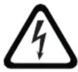
DANGER!
High risk: This symbol indicates an imminently hazardous situation such as "Dangerous Voltage" inside the product. If not avoided, this will result in an electrical shock, serious bodily injury, or death.

WARNING!
Medium risk: Indicates a potentially hazardous situation. If not avoided, this could result in minor or moderate bodily injury.

CAUTION!
Low risk: Indicates a potentially hazardous situation. If not avoided, this could result in property damage or risk of damage to the unit.
1.2 Important safety instructions
Read, follow, and retain for future reference all of the following safety instructions. Heed all warnings on the unit and in the operating instructions before operating the unit.
-
Cleaning - Unplug the unit from the outlet before cleaning. Follow any instructions provided with the unit. Generally, using a dry cloth for cleaning is sufficient but a moist, fluff-free cloth or leather shammy may also be used. Do not use liquid cleaners or aerosol cleaners.
-
Heat Sources - Do not install the unit near any heat sources such as radiators, heaters, stoves, or other equipment (including amplifiers) that produce heat.
-
Ventilation - Any openings in the unit enclosure are provided for ventilation to prevent overheating and ensure reliable operation. Do not block or cover these openings. Do not place the unit in an enclosure unless proper ventilation is provided, or the manufacturer's instructions have been adhered to.
-
Water - Do not use this unit near water, for example near a bathtub, washbowl, sink, laundry basket, in a damp or wet basement, near a swimming pool, in an outdoor installation, or in any area classified as a wet location. To reduce the risk of fire or electrical shock, do not expose this unit to rain or moisture.
-
Object and liquid entry - Never push objects of any kind into this unit through openings as they may touch dangerous voltage points or short-out parts that could result in a fire or electrical shock. Never spill liquid of any kind on the unit. Do not place objects filled with liquids, such as vases or cups, on the unit.
-
Lightning - For added protection during a lightning storm, or when leaving this unit unattended and unused for long periods, unplug the unit from the wall outlet and disconnect the cable system. This will prevent damage to the unit from lightning and power line surges.
-
Controls adjustment - Adjust only those controls specified in the operating instructions. Improper adjustment of other controls may cause damage to the unit. Use of controls or adjustments, or performance of procedures other than those specified, may result in hazardous radiation exposure.
-
Overloading - Do not overload outlets and extension cords. This can cause fire or electrical shock.
-
Power cord and plug protection - Protect the plug and power cord from foot traffic, being pinched by items placed upon or against them at electrical outlets, and its exit from the unit. For units intended to operate with 230 VAC, 50 Hz, the input and output power cord must comply with the latest versions of IEC Publication 227 or IEC Publication 245.
-
Power disconnect - Units have power supplied to the unit whenever the power cord is inserted into the power source. The power cord plug is the main power disconnect device for switching off the voltage for all units.
-
Power sources - Operate the unit only from the type of power source indicated on the label. Before proceeding, be sure to disconnect the power from the cable to be installed into the unit.
- For battery powered units, refer to the operating instructions.
- For external power supplied units, use only the recommended or approved power supplies.
- For limited power source units, this power source must comply with EN60950. Substitutions may damage the unit or cause fire or shock.
- For 24 VAC units, voltage applied to the unit's power input should not exceed ± 10% , or 28 VAC. User-supplied wiring must comply with local electrical codes (Class 2 power levels). Do not ground the
supply at the terminals or at the unit's power supply terminals.
- If unsure of the type of power supply to use, contact your dealer or local power company.
-
Servicing - Do not attempt to service this unit yourself. Opening or removing covers may expose you to dangerous voltage or other hazards. Refer all servicing to qualified service personnel.
-
Damage requiring service - Unplug the unit from the main AC power source and refer servicing to qualified service personnel when any damage to the equipment has occurred, such as:
-
the power supply cord or plug is damaged;
- exposure to moisture, water, and/or inclement weather (rain, snow, etc.);
– liquid has been spilled in or on the equipment; - an object has fallen into the unit;
- unit has been dropped or the unit cabinet is damaged;
- unit exhibits a distinct change in performance;
-
unit does not operate normally when the user correctly follows the operating instructions.
-
Replacement parts - Be sure the service technician uses replacement parts specified by the manufacturer, or that have the same characteristics as the original parts. Unauthorized substitutions may cause fire, electrical shock, or other hazards.
-
Safety check - Safety checks should be performed upon completion of service or repairs to the unit to ensure proper operating condition.
-
Installation - Install in accordance with the manufacturer's instructions and in accordance with applicable local codes.
-
Attachments, changes or modifications - Only use attachments/accessories specified by the manufacturer. Any change or modification of the equipment, not expressly approved by Bosch, could void the warranty or, in the case of an authorization agreement, authority to operate the equipment.
1.3 Important Notices
All-pole power switch - Incorporate an all-pole power switch, with a contact separation of at least 3 mm in each pole, into the electrical installation. If it is needed to open the housing for servicing and/or other activities, use this all-pole switch as the main disconnect device for switching off the voltage to the unit.
Environmental statement - Bosch has a strong commitment towards the environment. This unit has been designed to respect the environment as much as possible.
Fuse rating - For protection of the device, the branch circuit protection must be secured with a maximum fuse rating of 16A. This must be in accordance with NEC800 (CEC Section 60).
Grounding and polarization - This unit may be equipped with a polarized alternating current line plug (a plug with one blade wider than the other blade). This safety feature allows the plug to fit into the power outlet in only one way. If unable to insert the plug fully into the outlet, contact a locally certified electrician to replace the obsolete outlet. Do not defeat the safety purpose of the polarized plug.
Alternately, this unit may be equipped with a 3-pole grounding plug (a plug with a third pin for earth grounding). This safety feature allows the plug to fit into a grounded power outlet only. If unable to insert the plug into the outlet, contact a locally certified electrician to replace the obsolete outlet. Do not defeat the safety purpose of the grounding plug.
Moving - Disconnect the power before moving the unit. Move the unit with care. Excessive force or shock may damage the unit.
Outdoor signals - The installation for outdoor signals, especially regarding clearance from power and lightning conductors and transient protection, must be in accordance with NEC725 and NEC800 (CEC Rule 16-224 and CEC Section 60).
Permanently connected equipment - Incorporate a readily accessible disconnect device external to the equipment.
Pluggable equipment - Install the socket outlet near the equipment so it is easily accessible.
1.4 FCC & ICES compliance
FCC & ICES Information
(U.S.A. and Canadian Models Only)
This equipment has been tested and found to comply with the limits for a Class B digital device, pursuant to part 15 of the FCC Rules. These limits are designed to provide reasonable protection against harmful interference in a residential installation. This equipment generates, uses, and can radiate radio frequency energy and, if not installed and used in accordance with the instructions, may cause harmful interference to radio communications. However, there is no guarantee that interference will not occur in a particular installation. If this equipment does cause harmful interference to radio or television reception, which can be determined by turning the equipment off and on, the user is encouraged to try to correct the interference by one or more of the following measures:
- reorient or relocate the receiving antenna;
– increase the separation between the equipment and receiver; - connect the equipment into an outlet on a circuit different from that to which the receiver is connected;
- consult the dealer or an experienced radio/TV technician for help.
Intentional or unintentional modifications, not expressly approved by the party responsible for compliance, shall not be made. Any such modifications could void the user's authority to operate the equipment. If necessary, the user should consult the dealer or an experienced radio/television technician for corrective action.
The user may find the following booklet, prepared by the Federal Communications Commission, helpful: How to Identify and Resolve Radio-TV Interference Problems. This booklet is available from the U.S. Government Printing Office, Washington, DC 20402, Stock No. 004-000-00345-4.
1.5 UL certification
Disclaimer
Underwriter Laboratories Inc. ("UL") has not tested the performance or reliability of the security or signaling aspects of this product. UL has only tested fire, shock and/or casualty hazards as outlined in UL's Standard(s) for Safety for Closed Circuit Television Equipment, UL 2044. UL Certification does not cover the performance or reliability of the security or signaling aspects of this product.
UL MAKES NO REPRESENTATIONS, WARRANTIES, OR CERTIFICATIONS WHATSOEVER REGARDING THE PERFORMANCE OR RELIABILITY OF ANY SECURITY OR SIGNALING RELATED FUNCTIONS OF THIS PRODUCT.
Disclaimer
Underwriter Laboratories Inc. ("UL") has not tested the performance or reliability of the security or signaling aspects of this product. UL has only tested fire, shock and/or casualty hazards as outlined in UL's Standard(s) for Safety for Information Technology Equipment, UL 60950-1. UL Certification does not cover the performance or reliability of the security or signaling aspects of this product.
UL MAKES NO REPRESENTATIONS, WARRANTIES, OR CERTIFICATIONS WHATSOEVER REGARDING THE PERFORMANCE OR RELIABILITY OF ANY SECURITY OR SIGNALING-RELATED FUNCTIONS OF THIS PRODUCT.
1.6 Bosch notices
natural_image
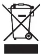
Symbol of a trash bin crossed with a diagonal line, no text or numbers presentDisposal - Your Bosch product was developed and manufactured with high-quality material and components that can be recycled and reused. This symbol means that electronic and electrical appliances, which have reached the end of their working life, must be collected and disposed of separately from household waste material. Separate collecting systems are usually in place for disused electronic and electrical products. Please dispose of these units at an environmentally compatible recycling facility, per European Directive 2002/96/EC
Copyright
This manual is the intellectual property of Bosch Security Systems and is protected by copyright.
All rights reserved.
Trademarks
All hardware and software product names used in this document are likely to be registered trademarks and must be treated accordingly.
NOTE:
This manual has been compiled with great care and the information it contains has been thoroughly verified. The text was complete and correct at the time of printing. The ongoing development of the products may mean that the content of the user guide can change without notice. Bosch Security Systems accepts no liability for damage resulting directly or indirectly from faults, incompleteness or discrepancies between the user guide and the product described.
More information
For more information please contact the nearest Bosch Security Systems location or visit www.boschsecurity.com
2 Installation

CAUTION!
Installation should only be performed by qualified service personnel in accordance with the National Electrical Code or applicable local codes.
Disconnect the supply power before installing
2.1 Tools required
- Small flat blade screwdriver.
- Crosshead screwdriver.
- Wire cutter/stripper tool.
2.2 Opening the side covers
natural_image
Pure diagram of a rectangular plate with four corner holes and directional arrows, no text or symbols present.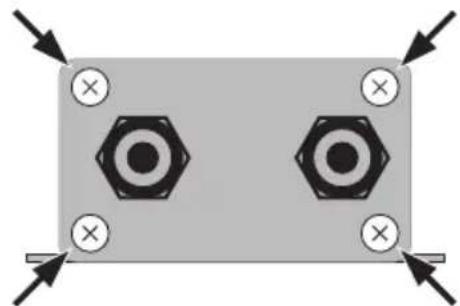
natural_image
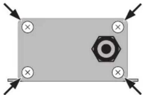
Pure electrical circuit lines without any symbolsFigure 2.1 Removing side covers
Unscrew the four cross-head screws at each corner and remove each of the side covers.
2.3 Mount the unit
natural_image
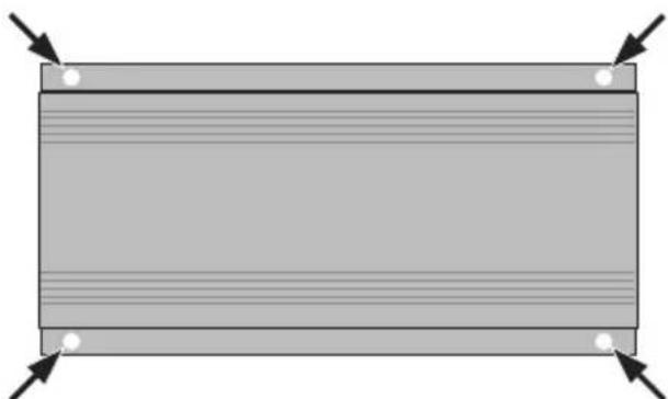
Pure diagram of a rectangular frame with four corner arrows pointing outward (no text or symbols)Figure 2.2 Mounting the unit
Secure the unit to a flat surface using mounting screws (not supplied) in the four holes (4 mm) shown in the figure.
2.4 Connecting the input cable
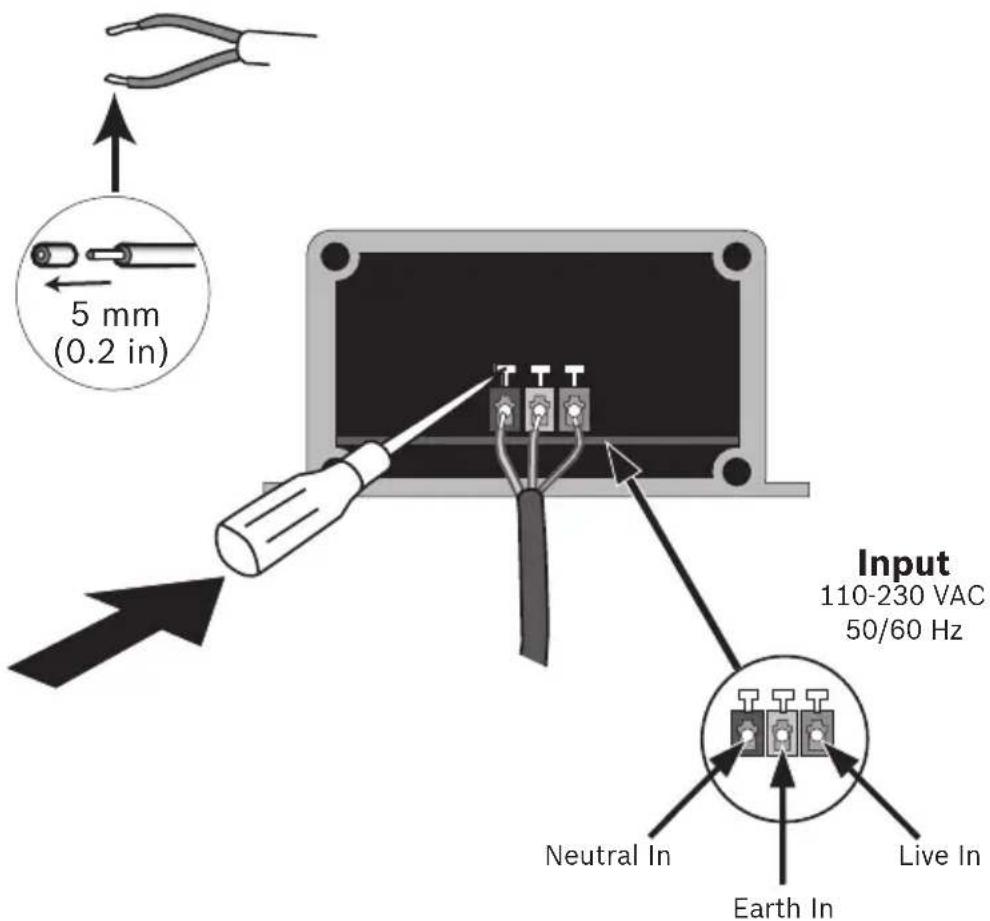
Figure 2.3 Connecting the input cable
Connect input supply cable as follows:
- Cut back the insulation of the cable wires to approximately 5 mm (0.2 in).
- Pass the input cable through the supplied grommet.
- For each wire, push back the tab behind the terminal with a small screwdriver and insert the wire (respect the polarity shown in the figure); release the tab to clamp the wire in place.
- Secure the grommet firmly.
- Return the protective cover to its position and fasten in place with the four cross-head screws.
Note:
Tighten screws firmly to ensure protection against water ingress.
2.5 Connecting the output cables
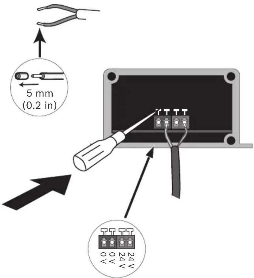
Figure 2.4 Connecting the output cables
Connect the two output cables as follows:
- Cut back the insulation of the cable wires to approximately 5 mm (0.2 in).
- Pass the output cables through the supplied grommets.
- For each wire, push back the tab behind the terminal with a small screwdriver and insert the wire (respect the polarity shown in the figure); release the tab to clamp the wire in place.
- Secure the grommets firmly.
- Return the protective cover to its position and fasten in place with the four cross-head screws.
Note:
Tighten screws firmly to ensure protection against water ingress.
3 Technical Data
3.1 Specifications
| Model PSU-22 | 4-DC100 | |
| Output | ||
| DC voltage 24 VDC | ||
| Rated current 4.0 A | ||
| Rated power 96 W (total both outputs) | ||
| Input | ||
| Voltage range 100 to 240 VAC | ||
| Frequency range 50 to 60 Hz | ||
| AC current 1.5 A (115 VAC) | ||
| 0.5 A (230 VAC) | ||
| Construction | ||
| Weight | 1.25 kg | |
| Material Casing: Aluminum extrusion; End-caps: mild steel. | ||
| Finish | Powder coated paint RAL 9010 (Pure White) | |
| Cable glands | Suitable for cable diameter 4 to 8 mm | |
| Environment | ||
| Water protection | IP66 | |
| Working temperature | -30 to +50°C | |
| Working humidity | 20 to 95% RH non-condensing | |
| Storage temperature | -40 to +80°C | |
| Storage humidity | 10 to 95% RH non-condensing |
| Safety & EMC | Safety standards EN60950-1UL60950-1EN60950-22, IP66 |
| Harmonic current Compliance to Class C (less than 75% load); EN61000-3-3 | |
| EMS immunity Compliance to EN61000-4-2,3,4,5,6,8,11; ENV50204, EN55024, EN61547, light industry level (surge 4KV), criteria A |
3.1.1 Dimensions
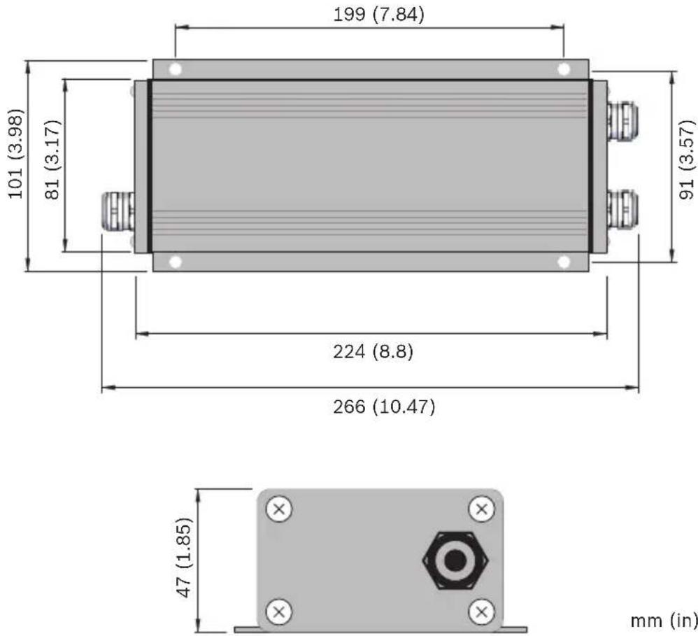
Figure 3.1 Dimensions
Bosch Security Systems
www.boschsecurity.com
© Bosch Security Systems, 2010
- Power Supply
- BOSCH
- Table of Contents
- S a f e t y
- Installation 13
- Technical Data 16
- Safety precautions
- DANGER!
- WARNING!
- CAUTION!
- Important safety instructions
- Important Notices
- FCC & ICES compliance
- FCC & ICES Information
- UL certification
- Disclaimer
- Bosch notices
- Copyright
- Trademarks
- NOTE:
- More information
- Installation
- Tools required
- Opening the side covers
- Mount the unit
- Connecting the input cable
- Connecting the output cables
- Technical Data
- Dimensions
Brand : BOSCH
Model : PSU-224-DC100
Category : Computer Adapter