MET-13 - Remote control AMX - Free user manual and instructions
Find the device manual for free MET-13 AMX in PDF.


| Product Type | Remote Control |
| Brand | AMX |
| Model | MET-13 |
| Dimensions (approx.) | 6.3 x 2.1 x 0.9 inches (160 x 53 x 23 mm) |
| Weight (without batteries) | 4.2 oz (120 g) |
| Power Source | 2 x AAA batteries (DC 3V) |
| Battery Life | Up to 12 months under normal use |
| Connectivity | Infrared (IR) and Radio Frequency (RF) 2.4 GHz |
| Range (IR) | Up to 30 feet (10 m) line-of-sight |
| Range (RF) | Up to 100 feet (30 m) through walls |
| Supported Devices | AMX control systems and compatible AV equipment |
| Number of Keys | 13 programmable keys |
| Display | LCD screen with backlight |
| Programming | Via AMX NetLinx Studio or IR Learner |
| Firmware Update | Via USB or network connection |
| Material | High-impact plastic with rubberized grip |
| Color | Black |
| Operating Temperature | 32°F to 104°F (0°C to 40°C) |
| Storage Temperature | -4°F to 140°F (-20°C to 60°C) |
| Humidity | 10% to 90% RH (non-condensing) |
| Certifications | FCC, CE, RoHS |
Frequently Asked Questions - MET-13 AMX
User questions about MET-13 AMX
0 question about this device. Answer the ones you know or ask your own.
Ask a new question about this device
Download the instructions for your Remote control in PDF format for free! Find your manual MET-13 - AMX and take your electronic device back in hand. On this page are published all the documents necessary for the use of your device. MET-13 by AMX.
USER MANUAL MET-13 AMX
IMPORTANT SAFETY INSTRUCTIONS
-
READ these instructions.
-
KEEP these instructions.
-
HEED all warnings.
-
FOLLOW all instructions.
-
DO NOT use this apparatus near water.
-
CLEAN ONLY with dry cloth.
-
DO NOT block any ventilation openings. Install in accordance with the manufacturer's instructions.
-
DO NOT install near any heat sources such as radiators, heat registers, stoves, or other apparatus (including amplifiers) that produce heat.
-
DO NOT defeat the safety purpose of the polarized or grounding type plug. A polarized plug has two blades with one wider than the other. A grounding type plug has two blades and a third grounding prong. The wider blade or the third prong are provided for your safety. If the provided plug does not fit into your outlet, consult an electrician for replacement of the obsolete outlet.
-
PROTECT the power cord from being walked on or pinched, particularly at plugs, convenience receptacles, and the point where they exit from the apparatus.
-
ONLY USE attachments/accessories specified by the manufacturer.

-
USE ONLY with a cart, stand, tripod, bracket, or table specified by the manufacturer, or sold with the apparatus. When a cart is used, use caution when moving the cart/apparatus combination to avoid injury from tip-over.
-
UNPLUG this apparatus during lightning storms or when unused for long periods of time.
-
REFER all servicing to qualified service personnel. Servicing is required when the apparatus has been damaged in any way, such as power-supply cord or plug is damaged, liquid has been spilled or objects have fallen into the apparatus, the apparatus has been exposed to rain or moisture, does not operate normally, or has been dropped.
-
DO NOT expose this apparatus to dripping or splashing and ensure that no objects filled with liquids, such as vases, are placed on the apparatus.
-
To completely disconnect this apparatus from the AC Mains, disconnect the power supply cord plug from the AC receptacle.
-
Where the mains plug or an appliance coupler is used as the disconnect device, the disconnect device shall remain readily operable.
-
DO NOT overload wall outlets or extension cords beyond their rated capacity as this can cause electric shock or fire.

The exclamation point, within an equilateral triangle, is intended to alert the user to the presence of important operating and maintenance (servicing) instructions in the literature accompanying the product.
The lightning flash with arrowhead symbol within an equilateral triangle is intended to alert the user to the presence of uninsulated "dangerous voltage" within the product's enclosure that may be of sufficient magnitude to constitute a risk of electrical shock to persons.

ESD Warning: The icon to the left indicates text regarding potential danger associated with the discharge of static electricity from an outside source (such as human hands) into an integrated circuit, often resulting in damage to the circuit.
WARNING: To reduce the risk of fire or electrical shock, do not expose this apparatus to rain or moisture.
WARNING: No naked flame sources - such as candles - should be placed on the product.
WARNING: Equipment shall be connected to a MAINS socket outlet with a protective earthing connection.
COPYRIGHT NOTICE
AMX© 2015, all rights reserved. No part of this publication may be reproduced, stored in a retrieval system, or transmitted, in any form or by any means, electronic, mechanical, photocopying, recording, or otherwise, without the prior written permission of AMX. Copyright protection claimed extends to AMX hardware and software and includes all forms and matters copyrightable material and information now allowed by statutory or judicial law or herein after granted, including without limitation, material generated from the software programs which are displayed on the screen such as icons, screen display looks, etc. Reproduction or disassembly of embodied computer programs or algorithms is expressly prohibited.
LIABILITY NOTICE
No patent liability is assumed with respect to the use of information contained herein. While every precaution has been taken in the preparation of this publication, AMX assumes no responsibility for error or omissions. No liability is assumed for damages resulting from the use of the information contained herein. Further, this publication and features described herein are subject to change without notice.
AMX WARRANTY AND RETURN POLICY
The AMX Warranty and Return Policy and related documents can be viewed/downloaded at www.amx.com.
ESD WARNING
 | To avoid ESD (Electrostatic Discharge) damage to sensitive components, make sure you are properly grounded before touching any internal materials.When working with any equipment manufactured with electronic devices, proper ESD grounding procedures must be followed to make sure people, products, and tools are as free of static charges as possible. Grounding straps, conductive smocks, and conductive work mats are specifically designed for this purpose. These items should not be manufactured locally, since they are generally composed of highly resistive conductive materials to safely drain static discharges, without increasing an electrocution risk in the event of an accident.Anyone performing field maintenance on AMX equipment should use an appropriate ESD field service kit complete with at least a dissipative work mat with a ground cord and a UL listed adjustable wrist strap with another ground cord |



WARNING: Do Not Open! Risk of Electrical Shock. Voltages in this equipment are hazardous to life. No user-serviceable parts inside. Refer all servicing to qualified service personnel.
Place the equipment near a main power supply outlet and make sure that you can easily access the power breaker switch.
WARNING: This product is intended to be operated ONLY from the voltages listed on the back panel or the recommended, or included, power supply of the product. Operation from other voltages other than those indicated may cause irreversible damage to the product and void the products warranty. The use of AC Plug Adapters is cautioned because it can allow the product to be plugged into voltages in which the product was not designed to operate. If the product is equipped with a detachable power cord, use only the type provided with your product or by your local distributor and/or retailer. If you are unsure of the correct operational voltage, please contact your local distributor and/or retailer.
FCC AND CANADA EMC COMPLIANCE INFORMATION:
This device complies with part 15 of the FCC Rules. Operation is subject to the following two conditions:
(1) This device may not cause harmful interference, and (2) this device must accept any interference received, including interference that may cause undesired operation.
NOTE: This equipment has been tested and found to comply with the limits for a Class B digital device, pursuant to part 15 of the FCC Rules. These limits are designed to provide reasonable protection against harmful interference in a residential installation. This equipment generates, uses and can radiate radio frequency energy and, if not installed and used in accordance with the instructions, may cause harmful interference to radio communications. However, there is no guarantee that interference will not occur in a particular installation. If this equipment does cause harmful interference to radio or television reception, which can be determined by turning the equipment off and on, the user is encouraged to try to correct the interference by one or more of the following measures:
•Reorient or relocate the receiving antenna.
- Increase the separation between the equipment and receiver.
- Connect the equipment into an outlet on a circuit different from that to which the receiver is connected.
- Consult the dealer or an experienced radio/TV technician for help.
Approved under the verification provision of FCC Part 15 as a Class B Digital Device.
Caution: Changes or modifications not expressly approved by the manufacturer could void the user's authority to operate this device.
This Class B digital apparatus complies with Canadian ICES-003.
Eligible to bear the CE mark; Conforms to European Union Low Voltage Directive 2006/95/EC; European Union EMC Directive 2004/108/EC; European Union Restriction of Hazardous Substances Recast (RoHS2) Directive 2011/65/EU; European Union WEEE (recast) Directive 2012/19/EU; European Union Registration, Evaluation, Authorization and Restriction of Chemicals (REACH) Directive 2006/121/EC.
You may obtain a free copy of the Declaration of Conformity by visiting http://www.amx.com/techcenter/certifications.asp.
WEEE NOTICE:
 | This appliance is labeled in accordance with European Directive 2012/19/EU concerning waste of electrical and electronic equipment (WEEE). This label indicates that this product should not be disposed of with household waste. It should be deposited at an appropriate facility to enable recovery and recycling. |
Table of Contents
Metreau® Keypads 10
Overview 10
Metreau Keypads with Ethernet 10
Metreau Keypads with AxLink 10
Metreau Audio Keypads (SWT Compatible) 10
Overview - Speaker Wire Technology (SWT).... 11
Metreau Keypads Device Family 11
MET-6N and MET-6NE 6-Button Keypads with Navigation.... 12
MET-6N Specifications 12
MET-6NE Specifications.... 13
Navigation Wheel.... 14
Pushbuttons 7-11.... 14
Navigation Wheel.... 14
MET-7, MET-7E, and MET-7X 7-Button Keypads.... 14
MET-7 Specifications 15
MET-7E Specifications 15
MET-7X Specifications 16
MET-13, MET-13E, and MET-13X 13-Button Keypads 17
MET-13 Specifications 17
MET-13E Specifications 18
MET-13X Specifications.... 18
DAS-MET-6SRC Metreau 6-Source Audio Keypad.... 19
DAS-MET-6SRC Specifications.... 19
Pushbuttons 1-6 20
Navigation Wheel.... 20
DAS-MET-NUM Metreau Numeric Audio Keypad 20
DAS-MET-NUM Specifications.... 21
Custom Button Installation 22
Overview 22
Removing Buttons 22
Button Kits.... 22
Audio....22
Residential 22
Commercial.... 22
Custom Keypads and Buttons 23
AxLink Device Addressing 24
Overview 24
Device Addressing on MET-6N Keypads.... 24
Setting the AxLink Device Address.... 24
Mounting and Installation 26
Overview 26
Mounting Dimensions.... 26
MET-6N, DAS-MET-6SRC 26
MET-6NE....27
MET-7 28
MET-7E, MET-7X 29
MET-13, DAS-MET-NUM 30
MET-13E, MET-13X 31
Mounting Procedures.... 31
Wallbox Mounting 31
Podium Mounting.... 31
Accent Frame 31
Daisy-Chaining Keypads (Ethernet Keypads only) 32
Wiring and Connections 33
Overview 33
Ethernet Wiring 33
AxLink Wiring 34
MET-6N, MET-7, and MET-13 Rear Panel Components 34
AxLink Wiring Guidelines 34
Preparing Captive Wires.... 34
AxLink Data and Power Connections 35
Using AxLink for Data with an Auxiliary Power Supply.... 35
Orientation of AxLink Connectors.... 35
AxLink Status LED 36
SWT Wiring 36
DAS-MET-6SRC and DAS-MET-7 Rear Panel Components 36
Cable Type 36
Preparing Captive Wires.... 36
DAS-MET-6SRC - SWT Data and Power Connections.... 37
DAS-MET-NUM - Connecting to the Main DAS-MET-6SRC Keypad 37
Tango System Integration Drawings 38
Tango System Integration Drawing - Using Four-Conductor Speaker Wire 38
Tango System Integration Drawing - Using the Audio Zone Expander 38
SWT Special Wiring Configurations.... 39
Auxiliary Amplifier Configuration 39
Remote Amplifier Configuration.... 39
Two-Wire Configurations – Keypad for Control Only 40
Split Zone / Analog Volume Control 40
Configuring Metreau Keypads with Ethernet 41
Overview 41
Table of Contents
| Locating the IP Address of the Keypad | 41 |
| Simulating the ID Pushbutton | 41 |
| Toggling Between IP Addressing Modes: DHCP and Static IP | 41 |
| Assigning a Device ID to a Keypad | 41 |
| Resetting the Keypad | 42 |
| Restoring the Factory Image on the Keypad | 42 |
Updating Firmware 43
Sending Firmware to Metreau Keypads (AxLink)...... 43
Device Addressing on MET-6N Keypads 43
Sending Firmware to Metreau Keypads with Ethernet 44
Programming the SWT Metreau Keypads 44
Programming 45
Programming the Metreau Keypads 45
Button Layouts.... 45
Channels 45
Port Numbers...... 45
Programming the Navigation Wheel (MET-6N & MET-6NE) 46
Navigation Wheel - Buttons 7-11 46
Navigation Wheel - Buttons 12-13 46
Navigation Wheel - Level Control 46
Display Bargraph 46
Supported SEND_LEVELs 46
SEND_LEVEL 46
Supported SEND_COMMANDs.... 47
@BRT 47
@WBRT 47
BMODE 47
?EXPANSION....48
LED-DIS 48
LED-EN 48
REBOOT 48
SET_NDX_DESC 48
LED Feedback for 2-Position Pushbuttons 49
Terminal (Telnet) Commands 49
Establishing a Terminal Connection via Telnet 49
Telnet User Name and Password.... 50
Additional Notes 50
Setting a Telnet User Name and Password 50
Telnet Commands 50
? or Help.... 50
DEVICE STATUS 50
EXIT 50
FACTORYFWIMAGE 50
GET CONFIG....51
GET CONNECTION....51
GET DEVICE....51
GET DNS 51
Notes on Specific Telnet Clients 55
Windows Client Programs 55
Linux Telnet Client 55
Enabling/Disabling Telnet on the Keypad.... 55
SHOW LOG....55
Basic Keypad Functions - DAS-MET-6SRC 56
Overview 56
DAS-MET-6SRC - Listening to a CD or DVD 56
Selecting the Source for Playback.... 56
Changing Tracks.... 56
Pausing Playback.... 56
Listening to an iPod 56
Listening to the Radio 57
Adjusting the Volume 57
DAS-MET-6SRC - Audio Adjustment Mode 58
Adjusting Bass Level For a Room/Zone 58
Adjusting Treble Level For a Room/Zone 58
Adjusting Balance For a Room/Zone 59
Adjusting SRS Settings For a Room/Zone 59
Turning SRS Off.... 59
DAS-MET-6SRC - Privacy Mode Off/On 60
Turning Off Privacy Mode 60
Working with Sources 60
DAS-MET-6SRC - Zone Control (On/Off) 61
Turning a Single Zone On/Off 61
Turning On a Source in All Zones.... 61
Turning Off/On a Source in All Zones 61
Table of Contents
| Turning Off All Zones (System OFF) | 62 |
| DAS-MET-6SRC - Zone Control (Dynamic Pause) | 62 |
| Single Zone Listening To Source | 62 |
| Multiple Zones Listening To The Same Source | 63 |
| DAS-MET-6SRC - Using the Navigation Wheel | 63 |
| Using the Navigation Wheel with the Internal AM/FM Tuner | 63 |
| Using the Navigation Wheel with the Internal SIRIUS Tuner | 63 |
| Using the Navigation Wheel with a CD Player/Changer | 63 |
| Using the Navigation Wheel with a DVD Player/Changer | 64 |
| Using the Navigation Wheel with a Satellite Radio/Video Box | 64 |
| Using the Navigation Wheel with an Audio Server | 64 |
| Using the Navigation Wheel with an External Tuner | 65 |
| Using the Navigation Wheel with Other Sources | 65 |
Advanced Functions - DAS-MET-6SRC 66
Overview 66
Direct Access 66
On-Board Tuner - Direct Selection of a Radio Station 66
CD Player - Direct Selection of a Disk and Track.... 66
CD Player - Direct Selection of a Track on the Current Disk.... 67
Cable and Satellite - Direct Selection of a Channel 67
Working with Presets 68
Creating a Preset 68
Recalling a Preset 68
Clearing All Presets 69
Working with Favorites....69
Creating a Favorite for a Specific Source 69
Clearing Favorites for All Sources in a Specific Zone 70
Working with Zone Grouping.... 70
Adding a Zone to a Group 70
Grouping All Zones 71
Un-Grouping All Zones 71
Grouping Volume Control 71
Working with Alarms 72
Setting the System Clock on the Tango Audio Controller 72
Setting an Alarm in a Zone.... 72
Clearing the Alarm for a Specific Zone 72
Clearing All Alarms for All Zones 73
Keypad Lockout.... 73
Locking a Keypad....73
Unlocking a Keypad 74
Unlocking All Keypads 74
Using the NetLinx Module ....77
Table of Contents
Overview 77
Main Page (Initial View) 77
Main Pages 78
Location/Device Pages 78
Zone Options....79
Change Source 79
Device Control Pages.... 80
Internal Tuner....80
Internal Sirius....81
DVD....82
CD....83
Audio Server 84
Satellite 85
External Tuner 86
Other 87
Setup Pages....88
Setup - Zones 88
Setup - Alarms 89
Adding an Alarm 89
Removing an Alarm.... 91
SWT Troubleshooting 92
Overview 92
Power Connections 92
Zone Connection Problems 92
Dead Zones 92
LED Does Not light.... 92
Source Connections.... 93
No Keypad Activity 93
Keypad Lights, No Sound 93
Metreau® Keypads
Overview
Metreau keypads are a convenient, versatile, cost-effective option for achieving effortless control of virtually anything through a NetLinx® control system. Metreau keypads offer easy installation within Decora-style wall plates and sleek styling that complements NetLinx Integrated Controllers (all keypads) and Tango Distributed Audio Systems (Audio Keypads only).
There are three basic variations within the Metreau device family:
Metreau Keypads with Ethernet
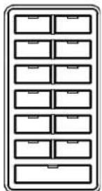
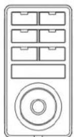
The MET-6NE, MET-7E and MET-13E keypads connect to a NetLinx control system via category cable. These keypads can be used as individual keypads or in conjunction with the MET-7X or MET-13X Metreau Ethernet Expansion Keypads.
natural_image
Front view of a retro television remote control unit with multiple drive bays and a circular button (no text or symbols)MET-6NE
MET-7E MET-13E
natural_image
Simple line drawing of a cabinet with 12 drawers arranged in two rows (no text or symbols)Metreau keypads (Ethernet)
FIG. 1 Metreau Keypads with Ethernet
Metreau Keypads with AxLink
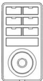
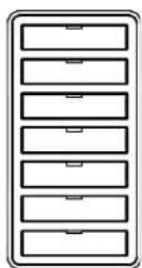
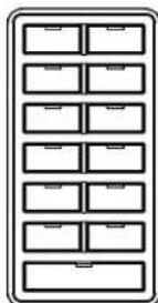
The MET-6N, MET-7 and MET-13 keypads are AxLink-compatible, for use with NetLinx control systems (FIG. 2).
MET-6N
MET-7 MET-13
Metreau keypads (AxLink)
FIG. 2 Metreau Keypads with AxLink
Metreau Audio Keypads (SWT Compatible)
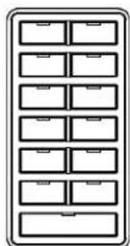
The DAS-MET-6SRC and DAS-MET-NUM are SWT-compatible, for use with Matrix Audio distribution systems, via Speaker Wire Technology (SWT). Metreau Audio keypads are compatible with all Matrix products including Tango and Mi Series Audio Controllers as well as XA Carbon Series Amplifiers (FIG. 3).
DAS-MET-6SRC
natural_image
Simple line drawing of a cabinet with multiple drawers arranged in two rows (no text or symbols)DAS-MET-NUM
Metreau Audio keypads (SWT)
FIG. 3 Metreau Audio keypads
Note: In terms of SWT functionality, the Metreau Audio keypads (DAS-MET-6SRC & DAS-MET-NUM) are a close match to previous versions of Matrix KP and NUM keypads.
Overview - Speaker Wire Technology (SWT)
Speaker Wire Technology (SWT) allows both data and audio signals to travel over the same four conductor wire. This remarkable technology removes the need for control wire since the control and audio signals are shared on the same wire. The reliability and simplicity of this system has been proven for years. AMX Matrix Audio is the only company that offers a "retrofit solution", one which allows the replacement of volume controls with AMX Matrix Audio keypads and Controllers, giving full control over the sources.
Additionally, the versatility of SWT also allows AMX Matrix Audio products to be connected where the control wire has been run separately from the speaker cable.
Metreau Keypads Device Family
All Metreau keypads are available in two colors: White and Black. Some older models are also available in Light Almond. The following table lists the keypads in the Metreau family, with descriptions and FG#s for each color.
| Metreau Keypads Device Family | ||
| Name Description Colors/FG#s | ||
| MET-6N | Metreau 6-Button Keypad with Navigation | White (FG5794-01-WH)Black (FG5794-01-BL)Light Almond (FG5794-01-LA) |
| MET-7 Metreau 7-Button Keypad • White (FG5794-03-WH) | Black (FG5794-03-BL)Light Almond (FG5794-03-LA) | |
| MET-13 Metreau 13-Button Keypad • White (FG5794-02-WH) | Black (FG5794-02-BL)Light Almond (FG5794-02-LA) | |
| MET-6NE | Metreau 6-Button Ethernet Keypad with Navigation | White (FG5793-01-WH)Black (FG5793-01-BL) |
| MET-7E | Metreau 7-Button Ethernet Keypad | White (FG5793-03-WH)Black (FG5793-03-BL) |
| MET-13E | Metreau 13-Button Ethernet Keypad | White (FG5793-02-WH)Black (FG5793-02-BL) |
| MET-7X | Metreau 7-Button Ethernet Expansion Keypad | White (FG5793-13-WH)Black (FG5793-13-BL) |
| MET-13X | Metreau 13-Button Ethernet Expansion Keypad | White (FG5793-12-WH)Black (FG5793-12-BL) |
| DAS-MET-6SRC | Metreau 6-Source Audio Keypad | White (FG1122-01-WH)Black (FG1122-01-BL)Light Almond (FG1122-01-LA) |
| DAS-MET-NUM | Metreau Numeric Audio Keypad | White (FG1122-02-WH)Black (FG1122-02-BL)Light Almond (FG1122-02-LA) |
MET-6N and MET-6NE 6-Button Keypads with Navigation
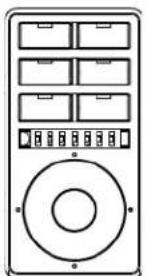
The Metreau 6-button keypads feature source control, visual volume feedback, and a navigation wheel that adjusts volume and provides up, down, left, right and center button options. FIG. 4 displays the MET-6N. The MET-6NE differs slightly in appearance, but has the same button functionality as the MET-6N.
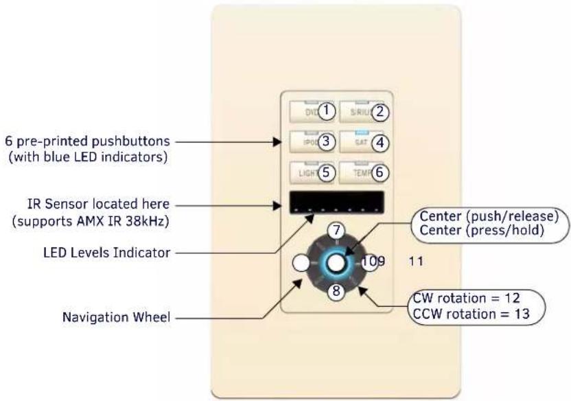
FIG. 4 MET-6N Metreau 6-Button keypad with Navigation (Light Almond shown)
The MET-6N is an AxLink keypad, suitable for use in NetLinx Control Systems.
MET-6N Specifications
| MET-6N Specifications | |
| Power: 12 VDC, 75 mA | |
| Front Panel Components: | Pushbuttons - 6 tactile pushbuttons with blue LED Indicators that illuminate when pressed to confirm the source/function was selected and that it is currently being used. These pre-printed buttons are field-replaceable.IR Sensor - Supports standard AMX IR (38 kHz only).LED Levels Indicator - set of 7 blue LEDs provide level feedback.Navigation Wheel - consists of 5 pushbuttons: 4 directional pushbuttons (Up, Down, Right, Left), 1 center pushbutton, and bi-directional rotating wheel for channel adjustments.The Navigation wheel itself provides two button functions as well (rotate CW = button #12, and rotate CCW = button #13, as indicated in FIG. 5). |
| Rear Panel Components: | DIP switch - 8 position mini DIP switch used to set the device address for the keypad on the AxLink Bus (1-255).AxLink connector - 4 pin 3.5mm Phoenix connector for AxLink connection to the NetLinx Master. |
| Dimensions (HWD): | Keypad and Mounting Plate: 4.055" x 1.772" x 0.997" (103mm x 45mm x 25.32mm)Mounts into standard Decora-style wall plates. |
| Weight: | 0.15 lbs. (0.068 kg) |
| Operating Environment: | Operating Temperature: 32° - 104° F (0° - 40° C).Relative Humidity: 5% - 85%, non-condensing.Intended for indoor use only. |
| Certifications: • FCC Class BCEIEC60950RoHS | |
| Colors: • White (FG5794-01-WH)Black (FG5794-01-BL)Light Almond (FG5794-01-LA) | |
| Optional Accessories: | Single Button Kit (FG5794-10)Lutron Cairo Wallplates (available in a variety of sizes and colors) |
The MET-6NE is an Ethernet keypad, suitable for use in NetLinx Control Systems.
MET-6NE Specifications
| MET-6NE Specifications | |
| Power: • PoE: PoE (Power over Ethernet), 802.3af, class 0• Power Connector: (1) RJ-45 Ethernet Connector, 10/100 | |
| Power Supply: | POE injector or switch (external, required), conforming to the 802.3af standard including AMX's PS-POE-AF-TC (FG423-83), not included |
| Front Panel Components: | • Pushbuttons - 6 tactile pushbuttons with blue LED indicators that illuminate when pressed to confirm the source/function was selected and that it is currently being used. These pre-printed buttons are field-replaceable.• IR Sensor - Supports standard AMX IR (38 kHz only).• LED Levels Indicator - set of 7 blue LEDs provide level feedback.• Navigation Wheel - consists of 5 pushbuttons: 4 directional pushbuttons (Up, Down, Right, Left), 1 center pushbutton, and bi-directional rotating wheel for channel adjustments.• The Navigation wheel itself provides two button functions as well (rotate CW = button #12, and rotate CCW = button #13, as indicated in FIG. 5). |
| Rear Panel Components: | • (1) RJ-45 Ethernet connector, 10/100• (1) 10-pin IDC-type connector for connection to expansion keypads |
| Dimensions (HWD): • Keypad and Mounting Plate: 4" x 1 3/4" x 1" (10.3 cm x 4.5 cm x 2.5 cm)• Mounts Into standard Decora-style wall plates. | |
| Weight: 0.17 lbs. (0.07 kg) | |
| Operating Environment: | • Operating Temperature: 32° - 104° F (0°- 40° C).• Relative Humidity: 5% - 85%, non-condensing.• Intended for indoor use only. |
| Certifications: • FCC Class B• CE• I E C 6 0 9 5 0• R o H S | |
| Colors: • White (FG5793-01-WH)• Black (FG5793-01-BL) | |
| Optional Accessories: | • PS-POE-AF-TC, PoE Injector, 802.3AF Compliant (FG423-83)• ALD-CW-1, 1-Gang Claro Wallplate (FG2605-81-BL/FG2605-81-WH)• ALD-CW-2, 2-Gang Claro Wallplate (FG2605-82-BL/FG2605-82-WH)• ALD-CW-3, 3-Gang Claro Wallplate (FG2605-83-BL/FG2605-83-WH)Can be used in conjunction with up to two Metreau Ethernet Expansion Keypads:• MET-13X-WH, Metreau 13-Button Expansion Keypad (FG5793-12-WH)• MET-13X-BL, Metreau 13-Button Expansion Keypad (FG5793-12-BL)• MET-7X-WH, Metreau 7-Button Expansion Keypad (FG5793-13-WH)• MET-7X-BL, Metreau 7-Button Expansion Keypad (FG5793-13-BL) |
Navigation Wheel
FIG. 5 shows the button layout of the Navigation Wheel:
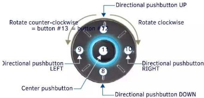
FIG. 5 Navigation Wheel - button layout (MET-6N displayed)
Pushbuttons 7-11
The top, bottom, left, right and center points on the Navigation Wheel are pushbuttons #7, #8, #9, #10 and #11, and can be programmed like any other button.
Navigation Wheel
The Navigation Wheel itself can be rotated clockwise and counterclockwise, and is intended to provide level control (for example volume or lighting levels).
- When rotated clockwise, the Navigation Wheel provides a channel event on button #12.
- When rotated counter-clockwise, the Navigation Wheel provides a channel event on button #13.
- The light on the Navigation Wheel can be illuminated by activating channel #11 (MET-6N only).
MET-7, MET-7E, and MET-7X 7-Button Keypads
The Metreau 7-button keypads offer 7 double-width buttons that can be used as in individual keypad or in conjunction with the 6-and 13-button Metreau keypads. FIG. 6 displays the MET-7. The MET-7E differs slightly in appearance, but has the same button functionality as the MET-7.
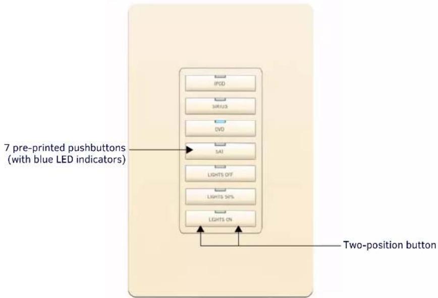
FIG. 6 MET-7 Metreau 7-Button keypad (Light Almond shown)
The MET-7 is an AxLink keypad, suitable for use in NetLinx Control Systems.
MET-7 Specifications
| MET-7 Specifications | |
| Power: 12 VDC, 30 mA | |
| Front Panel Components: | Pushbuttons - 7 tactile pushbuttons with blue LED indicators that illuminate when pressed to confirm the source/ function was selected and that it is currently being used. These pre-printed buttons are field-replaceable. The bottom button functions as 2 buttons - there are 2 positions (left and right) that allow the user to control channel/levels (up/down). |
| Rear Panel Components: | • DIP switch - 8-position mini DIP switch used to set the device address for the keypad on the AxLink Bus (1-255). • AxLink connector - 4-pin 3.5mm Phoenix connector for AxLink connection to the NetLinx Master. |
| Dimensions (HWD): • Keypad and Mounting Plate: 4.055" x 1.772" x 0.818" (103mm x 45mm x 207mm) • Mounts into standard Decora-style wall plates. | |
| Weight: 0.15 lbs. (0.068 kg) | |
| Operating Environment: | • Operating Temperature: 32° - 104° F (0°- 40° C). • Relative Humidity: 5% - 85%, non-condensing. • Intended for indoor use only. |
| Certifications: • FCC Class B • CE | • I E C 6 0 9 5 0 • R O H S |
| Colors: • White (FG5794-03-WH) • B I a c k ( FG5794-03-BL) • Light Almond (FG5794-03-LA) | |
| Optional Accessories: | • Single Button Kit (FG5794-10) • Double Button Kit (FG5794-11) • Lutron Cairo Wallplates (available in a variety of sizes and colors) |
MET-7E Specifications
The MET-7E is an Ethernet keypad, suitable for use in NetLinx Control Systems.
| MET-7E Specifications | |
| Power: • PoE: PoE (Power over Ethernet), 802.3af, class 0• Power Connector: (1) RJ-45 Ethernet Connector, 10/100 | |
| Power Supply: | POE injector or switch (external, required), conforming to the 802.3af standard including AMX's PS-POE-AF-TC (FG423-83), not included |
| Front Panel Components: | • Pushbuttons - 7 tactile pushbuttons with blue LED indicators that illuminate when pressed to confirm the source/function was selected and that it is currently being used. These pre-printed buttons are field-replaceable. |
| Rear Panel Components: | • (1) RJ-45 Ethernet connector, 10/100• (1) 10-pin IDC-type connector for connection to expansion keypads |
| Dimensions (HWD): • Keypad and Mounting Plate: 4" x 1 3/4" x 1" (10.3 cm x 4.5 cm x 2.5 cm)• Mounts into standard Decora-style wall plates. | |
| Weight: | 0.18 lbs. (0.08 kg) |
| Operating Environment: | • Operating Temperature: 32° - 104° F (0°- 40° C).• Relative Humidity: 5% - 85%, non-condensing.• Intended for Indoor use only. |
| Certifications: • FCC Class B • CE • I E C 6 0 9 5 0 • R o H S | |
| Colors: • White (FG5793-01-WH)• B l a c k ( FG5793-01-BL) | |
| Optional Accessories: | • PS-POE-AF-TC, PoE Injector, 802.3AF Compliant (FG423-83)• ALD-CW-1, 1-Gang Claro Wallplate (FG2605-81-BL/FG2605-81-WH)• ALD-CW-2, 2-Gang Claro Wallplate (FG2605-82-BL/FG2605-82-WH)• ALD-CW-3, 3-Gang Claro Wallplate (FG2605-83-BL/FG2605-83-WH)Can be used in conjunction with up to two Metreau Ethernet Expansion Keypads:• MET-13X-WH, Metreau 13-Button Expansion Keypad (FG5793-12-WH)• MET-13X-BL, Metreau 13-Button Expansion Keypad (FG5793-12-BL)• MET-7X-WH, Metreau 7-Button Expansion Keypad (FG5793-13-WH)• MET-7X-BL, Metreau 7-Button Expansion Keypad (FG5793-13-BL) |
MET-7X Specifications
The MET-7X is an Ethernet Expansion keypad, suitable for use in NetLinx Control Systems.
| MET-7X Specifications | |
| Power: | PoE: The Expansion Keypad receives power from the Metreau Ethernet Keypad it is connected to (options include MET-6NE, MET-7E and MET-13E) via the ribbon cable. See the power options for the connected Ethernet keypad for PoE specifications |
| Front Panel Components: | (7) tactile pushbuttons with blue LED indicators that illuminate when pressed to confirm the source/function was selected and that it is currently being used. These pre-printed buttons are field-replaceable. |
| Rear Panel Components: | • (1) 10-pin IDC-type connector for connection to additional expansion keypads• (1) ribbon cable for connection to Ethernet keypads |
| Dimensions (HWD): • Keypad and Mounting Plate: 4" x 1 3/4" x 1" (10.3 cm x 4.5 cm x 2.5 cm)• Mounts into standard Decora-style wall plates. | |
| Weight: 0.14 lbs. (0.06 kg) | |
| Operating Environment: | • Operating Temperature: 32° - 104° F (0° - 40° C).• Relative Humidity: 5% - 85%, non-condensing.• Intended for indoor use only. |
| Certifications: • FCC Class B• CE• I E C 6 0 9 5 0• R O H S | |
| Colors: • White (FG5793-01-WH)• B I a c k ( FG5793-01-BL) | |
| Optional Accessories: | • ALD-CW-1, 1-Gang Claro Wallplate (FG2605-81-BL/FG2605-81-WH)• ALD-CW-2, 2-Gang Claro Wallplate (FG2605-82-BL/FG2605-82-WH)• ALD-CW-3, 3-Gang Claro Wallplate (FG2605-83-BL/FG2605-83-WH) |
MET-13, MET-13E, and MET-13X 13-Button Keypads
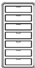
The Metreau 13-button keypads offer 13 buttons (12 single-width and 1 double-width) and can be used as in individual keypad or in conjunction with the 6- and 7-button Metreau keypads. FIG. 7 displays the MET-13. The MET-13E differs slightly in appearance, but has the same button functionality as the MET-13.
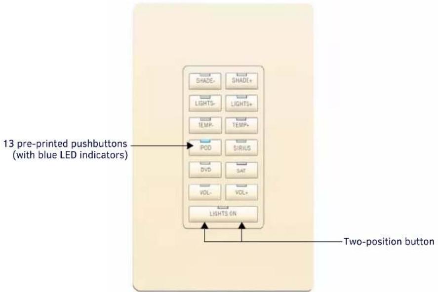
FIG. 7 MET-13 Metreau 13-Button keypad (Light Almond shown)
The MET-13 is an AxLink keypad, suitable for use in NetLinx Control Systems.
MET-13 Specifications
| MET-13 Specifications | |
| Power: 12 VDC, 30 mA | |
| Front Panel Components: | Pushbuttons - 13 tactile pushbuttons with blue LED indicators that illuminate when pressed to confirm the source/ function was selected and that it is currently being used (12 single-width, 1 double-width). These pre-printed buttons are field-replaceable.The bottom button functions as 2 buttons - there are 2 positions (left and right) that allow the user to control channels (up/down). |
| Rear Panel Components: | DIP switch - 8-position mini DIP switch used to set the device address for the keypad on the AxLink Bus (1-255).AxLink connector - 4-pin 3.5mm Phoenix connector for AxLink connection to the NetLinx Master. |
| Dimensions (HWD): Keypad and Mounting Plate: 4.055" x 1.772" x 0.818"(103mm x 45mm x 207mm)Mounts into standard Decora-style wall plates. | |
| Weight: 0.15 lbs. (0.068 kg) | |
| Operating Environment: | Operating Temperature: 32° - 104°F (0°- 40°C).Relative Humidity: 5% - 85%, non-condensing.Intended for indoor use only. |
| Certifications: • FCC Class BCEI E C 6 0 9 5 0Ro H S | |
| Colors: • White (FG5794-02-WH)B I a c k ( FG5794-02-BL)Light Almond (FG5794-02-LA) | |
| Optional Accessories: | Single Button Kit (FG5794-10)Double Button Kit (FG5794-11)Lutron Cairo Wallplates (available in a variety of sizes and colors) |
MET-13E Specifications
The MET-13E is an Ethernet keypad, suitable for use in NetLinx Control Systems.
| MET-13E Specifications | |
| Power: • PoE: PoE (Power over Ethernet), 802.3af, class 0• Power Connector: (1) RJ-45 Ethernet Connector, 10/100 | |
| Power Supply: | POE injector or switch (external, required), conforming to the 802.3af standard including AMX's PS-POE-AF-TC (FG423-83), not included |
| Front Panel Components: | (13) tactile pushbuttons with blue LED indicators that illuminate when pressed to confirm the source/function was selected and that it is currently being used. These pre-printed buttons are field-replaceable. |
| Rear Panel Components: | • (1) RJ-45 Ethernet connector, 10/100• (1) 10-pin IDC-type connector for connection to expansion keypads |
| Dimensions (HWD): • Keypad and Mounting Plate: 4" x 1 3/4" x 1" (10.3 cm x 4.5 cm x 2.5 cm)• Mounts into standard Decora-style wall plates. | |
| Weight: 0.18 lbs. (0.08 kg) | |
| Operating Environment: | • Operating Temperature: 32° - 104° F (0°- 40° C).• Relative Humidity: 5% - 85%, non-condensing.• Intended for indoor use only. |
| Certifications: • FCC Class B • CE • I E C 6 0 9 5 0 • R O H S | |
| Colors: • White (FG5793-01-WH)• B I a c k ( FG5793-01-BL) | |
| Optional Accessories: | • PS-POE-AF-TC, PoE Injector, 802.3AF Compliant (FG423-83)• ALD-CW-1, 1-Gang Claro Wallplate (FG2605-81-BL/FG2605-81-WH)• ALD-CW-2, 2-Gang Claro Wallplate (FG2605-82-BL/FG2605-82-WH)• ALD-CW-3, 3-Gang Claro Wallplate (FG2605-83-BL/FG2605-83-WH)Can be used in conjunction with up to two Metreau Ethernet Expansion Keypads:• MET-13X-WH, Metreau 13-Button Expansion Keypad (FG5793-12-WH)• MET-13X-BL, Metreau 13-Button Expansion Keypad (FG5793-12-BL)• MET-7X-WH, Metreau 7-Button Expansion Keypad (FG5793-13-WH)• MET-7X-BL, Metreau 7-Button Expansion Keypad (FG5793-13-BL) |
MET-13X Specifications
The MET-13X is an Ethernet Expansion keypad, suitable for use in NetLinx Control Systems.
| MET-13X Specifications | |
| Power: | PoE: The Expansion Keypad receives power from the Metreau Ethernet Keypad it is connected to (options include MET-6NE, MET-7E and MET-13E) via the ribbon cable. See the power options for the connected Ethernet keypad for PoE specifications |
| Front Panel Components: | (13) tactile pushbuttons with blue LED indicators that illuminate when pressed to confirm the source/function was selected and that it is currently being used. These pre-printed buttons are field-replaceable. |
| Rear Panel Components: | • (1) 10-pin IDC-type connector for connection to additional expansion keypads• (1) ribbon cable for connection to Ethernet keypads |
| Dimensions (HWD): • Keypad and Mounting Plate: 4" x 1 3/4" x 1" (10.3 cm x 4.5 cm x 2.5 cm)• Mounts into standard Decora-style wall plates. | |
| Weight: 0.14 lbs. (0.06 kg) | |
| Operating Environment: | • Operating Temperature: 32° - 104° F (0° - 40° C).• Relative Humidity: 5% - 85%, non-condensing.• Intended for indoor use only. |
| Certifications: • FCC Class B • CE • I E C 6 0 9 5 0 • R o H S | |
| Colors: • White (FG5793-01-WH)• B l a c k ( FG5793-01-BL) | |
| Optional Accessories: | • ALD-CW-1, 1-Gang Claro Wallplate (FG2605-81-BL/FG2605-81-WH)• ALD-CW-2, 2-Gang Claro Wallplate (FG2605-82-BL/FG2605-82-WH)• ALD-CW-3, 3-Gang Claro Wallplate (FG2605-83-BL/FG2605-83-WH) |
DAS-MET-6SRC Metreau 6-Source Audio Keypad
The DAS-MET-6SRC 6-button keypad (FIG. 8) features source control, visual volume feedback and a navigation wheel that adjusts volume and provides up, down, left, right and center button options (see the Basic Keypad Functions - DAS-MET-6SRC section on page 56 for information).
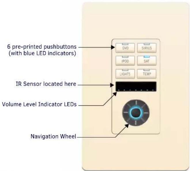
FIG. 8 DAS-MET-6SRC Metreau 6-Source Audio keypad (Light Almond shown)
The DAS-MET-6SRC is a SWT keypad, suitable for use in Matrix Distributed Audio Systems.
DAS-MET-6SRC Specifications
| DAS-MET-6SRC Specifications | |
| Power: 12 VDC, 125 mA | |
| Front Panel Components: | Pushbuttons - 6 tactile pushbuttons with blue LED indicators that illuminate when the source is selected, and stay lit until the source is turned off. These pre-printed buttons are field-replaceable.IR Sensor - Works specifically with the MIO-R1-AUDIO remote controller (38 kHz only).LED Levels Indicator - set of 7 blue LEDs provide volume level feedback.Navigation Wheel - consists of 5 pushbuttons: 4 directional pushbuttons (Up, Down, Right, Left), 1 center pushbutton, and bi-directional rotating wheel for volume adjustments.Note that the center pushbutton is dual-purpose: a push/release provides one function, while a press/hold provides another. |
| Rear Panel Components: | Wiring connection - Two 4-pin SWT connectors that provide connection from the Matrix Audio Controller, and to the speakers. |
| Dimensions (HWD):Keypad and Mounting Plate: 4.055" x 1.772" x 0.997"(103mm x 45mm x 25.32mm)Mounts into standard Decora-style wall plates. | |
| Weight: | 0.15 lbs. (0.068 kg) |
| Operating Environment: | Operating Temperature: 32° - 104°F (0° - 40°C).Relative Humidity: 5% - 85%, non-condensing.Intended for indoor use only. |
| Certifications: • FCC Class BCEIEC60950RoHS | |
| Colors: • White (FG1122-01-WH)Black (FG1122-01-BL)Light Almond (FG1122-01-LA) | |
| Optional Accessories: | Single Button Kit (FG5794-10)Lutron Cairo Wallplates (available in a variety of sizes and colors) |
Pushbuttons 1-6
The top, bottom, left and right points on the Navigation Wheel are used for source control and can be programmed to provide any source functionality by learning the applicable IR code.
The center pushbutton is dual-purpose: a push/release on this button provides one function, while a press/hold provides another. The center pushbutton are also used for source control and can be programmed to provide any source functionality (again, by learning the applicable IR code).
Navigation Wheel
FIG. 9 shows the button layout of the Navigation Wheel:
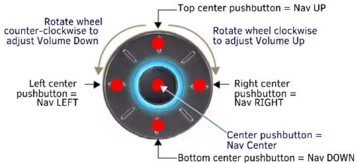
FIG. 9 Navigation Wheel - button layout
The Navigation Wheel can be rotated bi-directionally, and provides volume level control:
- Clockwise rotation increases the volume level, counter-clockwise rotation decreases the volume level.
• The range for volume is 0 - 70.
DAS-MET-NUM Metreau Numeric Audio Keypad
The DAS-MET-NUM Metreau numeric keypad (FIG. 10) connects to the Main DAS-MET-6SRC keypad via a 14-pin connector. Used in conjunction with the DAS-MET-6SRC Metreau keypad, it provides direct numeric access, setting & recalling presets, and access to advanced functionality such as grouping, Setting Favorites, Alarm, and Keypad lockout functionality (see the Advanced Functions - DAS-MET-6SRC section on page 66 for information).
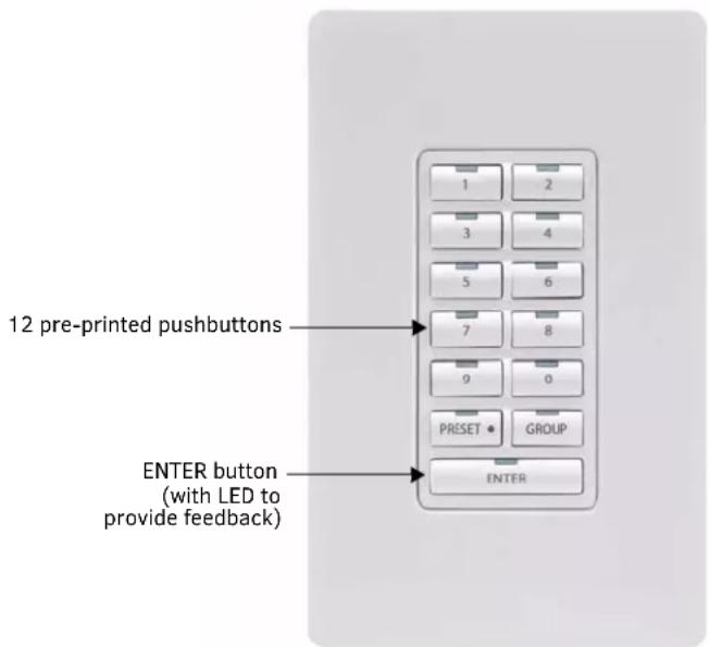
FIG. 10 DAS-MET-NUM Metreau Numeric Audio keypad (White shown)
The DAS-MET-NUM is a SWT keypad, suitable for use in Matrix Distributed Audio Systems.
DAS-MET-NUM Specifications
| DAS-MET-NUM Specifications | |
| Power: 12 VDC, 125 mA | |
| Front Panel Components: | Pushbuttons - 13 tactile pushbuttons. |
| Rear Panel Components: | Wiring connection - One 14-pin connector that provides connection to the main 6 Source Metreau Keypad (DAS-MET-6SRC). |
| Dimensions (HWD): • Keypad and Mounting Plate: 4.055" x 1.772" x 0.818"(103mm x 45mm x 207mm)• Mounts into standard Decora-style wall plates. | |
| Weight: 0.15 lbs. (0.068 kg) | |
| Operating Environment: | • Operating Temperature: 32° - 104°F (0°- 40°C).• Relative Humidity: 5% - 85%, non-condensing.• Intended for Indoor use only. |
| Certifications: • FCC Class B• CE | • I E C 6 0 9 5 0• R o H S |
| Colors: • White (FG1122-02-WH)• B l a c k ( FG1122-02-BL)• Light Almond (FG1122-02-LA) | |
| Optional Accessories: | • Single Button Kit (FG5794-10)• Double Button Kit (FG5794-11)• Lutron Cairo Wallplates (available in a variety of sizes and colors) |
Custom Button Installation
Overview
With the exception of the DAS-MET-NUM, all Metreau keypads feature field-replaceable pre-printed buttons. This section describes removing the original set of buttons and replacing them with custom buttons.
Removing Buttons
The easiest way to remove and replace buttons on the Metreau keypads is to place the keypad assembly (FIG. 11) face-down on a flat level surface, so that the buttons stay in position until you are ready to remove them.
IMPORTANT: Disconnect the power supply and all wiring connections before removing/replacing buttons on the Metreau keypads.
IMPORTANT: Before touching the device, discharge the static electricity from your body by touching a grounded metal object.
The Faceplate is attached to the Mounting Plate via four plastic tabs (two on each side of the Faceplate, as shown in FIG. 11). It is not necessary to remove the plastic faceplate from the Mounting Plate in order to replace buttons.
- The faceplate is attached to the mounting plate via four plastic tabs (two on each side of the faceplate, see FIG. 11). To remove the faceplate, gently pry it from either side.
- Gently lift each button off of their mounting posts on the circuit board.
- Select the location of the custom buttons and gently snap them into place on the Circuit Board.
Be sure to note the orientation of the LED window on each button, to avoid accidentally mounting them upside down.
- Reattach the plastic faceplate.
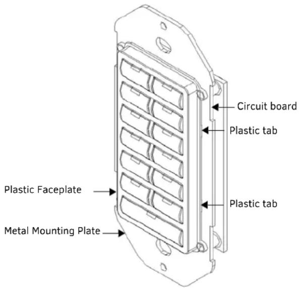
FIG. 11 Keypad assembly
Button Kits
Three different button kits, which accommodate most installations, are available for Metreau keypads:
Audio
SIRIUS, XM, IPOD, MP3, CD2, AUX2, DVD2, PC, FM.
Residential
LIGHTS, FAN, SHADES, HVAC+, HVAC-, UP, DOWN, TV.
Commercial
DISP, PROJ, VC, AC, HVAC, LIGHTS, SCREEN.
Custom Keypads and Buttons
If a requested keypad needs functions not offered in the standard Button Kits, a custom keypad may be built with the AMX Metreau Keypad Preview (FIG. 12), available at www.amx.com. This tool allows custom arrangement of default or custom button arrangements, creation of custom button text, previews of keypad type and color, and printouts of final keypad layouts and parts lists.
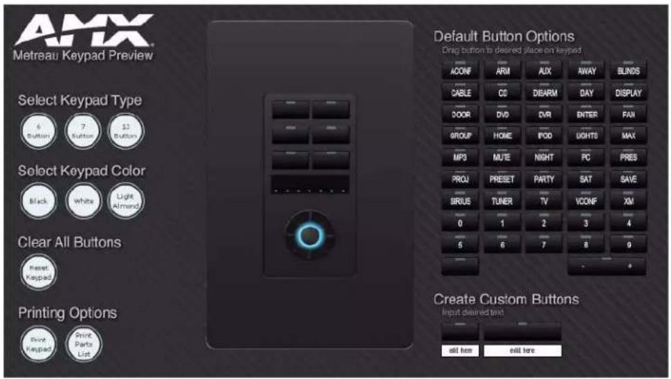
FIG. 12 Metreau Keypad Preview
AxLink Device Addressing
Overview
Metreau Keypads with AxLink used in NetLinx applications require a unique numeric AxLink device address of 1-255. Consider specifying the device address for each keypad before final installation.
NOTE: AxLink device addressing applies only to the MET-6N, MET-7, and MET-13 keypads. Metreau Audio Keypads (DAS-MET-6SRC and DAS-MET-13) do not require device addressing.
Device Addressing on MET-6N Keypads
- The MET-6N uses two AxLink devices addresses - one for the keypad itself, and a second one for the IR Receiver.
- The device address of the IR Receiver is auto-assigned to be one number higher than the device address of the keypad itself (to which the firmware is uploaded).
- The MET-6N will appear as two devices in the Devices frame, because it's built-in IR Receiver is recognized as a separate online device.
- Firmware is uploaded to the device address of the keypad (not the IR Receiver).
For example, if the MET-6N is set to device address 127, then the IR Receiver on that MET-6N will appear as device number 128. Firmware must be sent to the keypad, not the IR Receiver (in this example, device 127).
Setting the AxLink Device Address
AxLink-enabled Metreau keypads (MET-6N, MET-7 and MET-13) use an 8-position mini-DIP switch to specify a unique device address for each keypad in a NetLinx Control System (see FIG. 13).
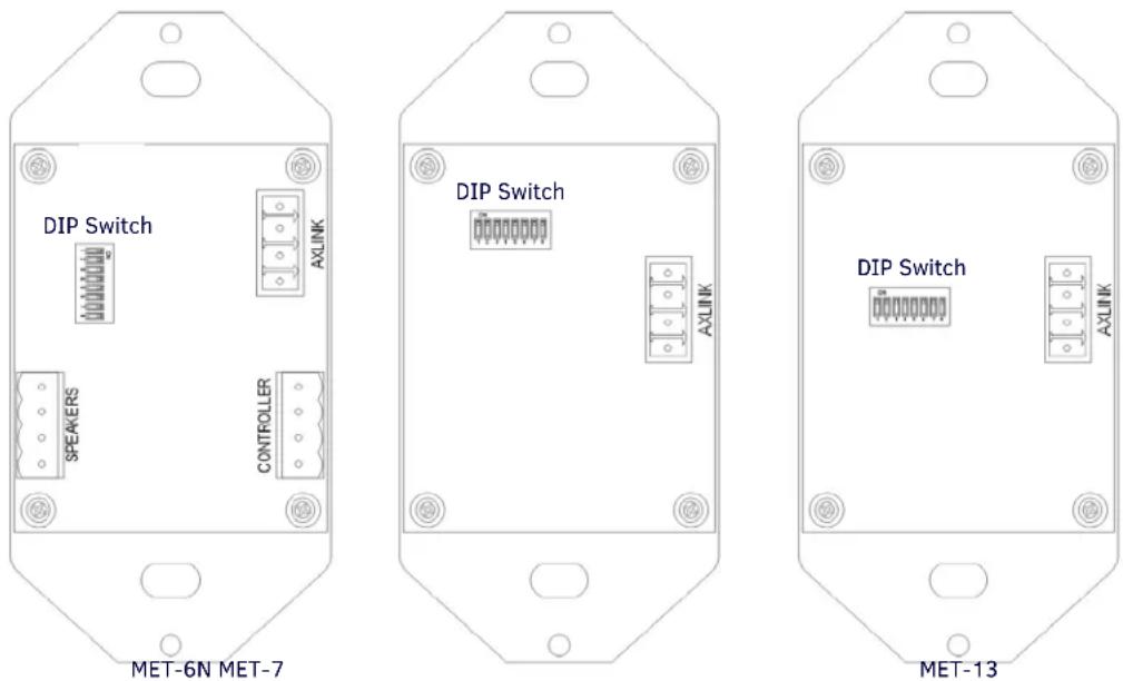
FIG. 13 DIP Switch and SWT Jumper locations
NOTE: Before touching the device, discharge the static electricity from your body by touching a grounded metal object.
- If connected, disconnect the power supply.
- Locate the 8-position mini-DIP switch on the rear panel.
- Set the DIP switch according to the values shown below.
| S w i | t | c | h | 1 | 2 | 3 | 4 | 5 | 6 |
| Value 1 2 | 4 | 8 | 16 | 32 | 64 | 128 |
7 8
The device number is set by the total value of DIP switch positions that are in the ON position. Note that the ON position is indicated on the DIP Switch.
As an example, the DIP switch in FIG. 14 defines AXlink device number 129 (1+128=129).
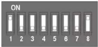
FIG. 14 8-position mini-DIP Switch
If you later change the device number, remove and reconnect the power connector to enter the new device number into memory.
NOTE: AMX has created the "Dip Switch2" software application to assist in calculating dip switch position values. Download the (free) program Dip Switch2 from www.amx.com.
Mounting and Installation
Overview
Metreau keypads are designed to install into standard U.S. Decora-style wall plates and boxes (wallboxes not included).
IMPORTANT: Before touching the device, discharge the static electricity from your body by touching a grounded metal object.
Mounting Dimensions
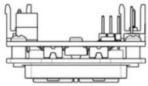
MET-6N, DAS-MET-6SRC
FIG. 15 provides detailed dimensions for the MET-6N and DAS-MET-6SRC keypads.
natural_image
Technical line drawing of a mechanical assembly with no visible text or symbols![1.772 [45,00] 4.055 [103,00]](/content/2026/05/959638/images/693b39264ce94f3ebf871a48f7bc2f1c4a09a95a4279c180d97250d915141093.jpg)
![0.583 [14,80] 0.247 [6,27] 0.693 [17,60] 0.997 [25,32]](/content/2026/05/959638/images/d567090c9606ec558718eda299d0e06ba4962a1464e31885740da160d104d924.jpg)
FIG. 15 MET-6N and DAS-MET-6SRC Mounting Dimensions
MET-6NE
FIG. 16 provides detailed dimensions for the MET-6NE keypad.
![4.06 [103.00] 3.28 [83.34] 1.36 [34.45] 1.30 [33.02] 1.77 [45.00] .30 [7.72] .87 [22.21] 2.71 [68.73] .67 [17.13] 1.20 [30.59]](/content/2026/05/959638/images/03eab464dc2e32adb7a09e40a2c0c1d9556d344f8478b3ace224100d00a6be83.jpg)
FIG. 16 MET-6NE Mounting Dimensions
MET-7
FIG. 17 provides detailed dimensions for the MET-7 keypads.
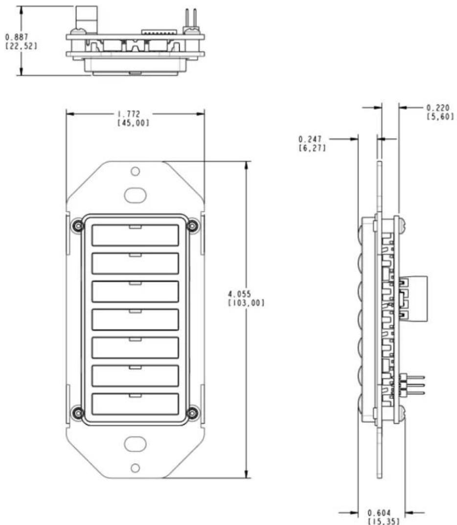
FIG. 17 MET-7 Mounting Dimensions
MET-7E, MET-7X
FIG. 18 provides detailed dimensions for the MET-7E and MET-7X keypads.
![4.06 3.28 [103.0] [83.3] 1.39 [35.2] 1.77 [45.0]](/content/2026/05/959638/images/2d457e12f66bb523da1aa3d643db304e897a3b5a318a0fb5902d9e48984c1666.jpg)
![MET-7E .30 [7.7] .87 [22.2] 2.71 [68,7] .67 [17,1] 1.20 [30,6]](/content/2026/05/959638/images/9141d3071210647480ae3ba19b08186c0316dba02669eb83f59ae95af669106f.jpg)
![MET-7X .22 [5.6] .30 [7.7] 2.71 [68.7] .67 [17.1] .44 [11.2]](/content/2026/05/959638/images/7125dbb97e9e74a3d95564560bcd503d306fc198735c561e34ada799f9d6929c.jpg)
FIG. 18 MET-7E and MET-7X Mounting Dimensions
MET-13, DAS-MET-NUM
FIG. 19 provides detailed dimensions for the MET-13 and DAS-MET-NUM keypads.
![0.887 [22.52]](/content/2026/05/959638/images/c54b0a9d03fea9bbe6646688229afdac27b2ae37dca280ceeef9432695a24e43.jpg)
![1,772 [45,00] 4,055 [103,00]](/content/2026/05/959638/images/a71fbff6b3d91310e404533d023cad73d1b16cbef9806716ec698542fec96fc5.jpg)
![0.583 [14,80] 0.247 [6,27] 0.604 [15,35]](/content/2026/05/959638/images/74f61dba5153520b7454dc6f93455783e6d966b1b023e68efdd75b7638feddd0.jpg)
FIG. 19 MET-13 and DAS-MET-NUM Mounting Dimensions
MET-13E, MET-13X
FIG. 20 provides detailed dimensions for the MET-13E and MET-13X keypads:
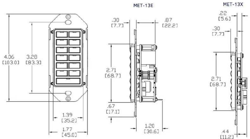
FIG. 20 MET-13E and MET-13X Mounting Dimensions
Mounting Procedures
AMX recommends mounting Metreau keypads in standard U.S.-style Decora wallboxes:
- Conduit box should meet NEC specs (section 370)
• Minimum internal clearance of (HWD) 2-5/8" x 1-3/4" x 1-5/8".
Wallbox Mounting
- Use the cutout dimension for the wallbox to cutout the install surface.
- Connect the AxLink connector (or SWT cable connectors) to the rear of the keypad.
- Place the Mounting Plate on the wallbox; align the screw holes with the mounting holes and fasten the Mounting Plate to the wallbox using the screws supplied.
NOTE: Do not over-tighten the screws when mounting the Mounting Frame. The device should be flush with mounting surface.
Podium Mounting
- Use the cutout dimension for the wallbox to cutout the Mounting Frame install surface for the keypad
- Confirm that the terminal end of the AxLink cable is disconnected, and not receiving power.
- Connect the AxLink power supply. The connector passes through the center of the Mounting Frame and connects to the board.
- With the Mounting Frame resting in the cutout area, drill the mounting holes into the flat surface.
NOTE: Do not over-tighten the screws when mounting the Mounting Frame. The device should be flush with mounting surface.
Accent Frame
While the Metreau device family does fit into many International wallboxes, it may be necessary to utilize the optional Accent Frame to completely cover the wallbox.
To install the keypad with the optional Accent Frame:
- Use the cutout dimension for the wallbox to cut out the install surface for the keypad.
- Place the Accent Frame on the wallbox; align the screw holes with the mounting holes on the wallplate. Fasten the wallplate to the wallbox.
Based on the extensive number of international wallboxes it is not pragmatic to ship every possible screw that could be used. Please use the screws appropriate for your specific wallbox.
NOTE: Do not over-tighten the screws when mounting the Mounting Frame. The device should be flush with mounting surface.
- Confirm that the terminal end of the AxLink cable is disconnected, and not receiving power.
- Connect the power supply. The connector passes through the center of the Mounting Frame and connects to the board.
- Place the Mounting Frame on the Accent Frame; align the screw holes with the mounting holes and fasten the Mounting Frame to the wallplate. The Accent Frame is shipped with two #6-32 x .187 long flat head screws (80-131); these are used to attach the keypad to the accent frames.
Daisy-Chaining Keypads (Ethernet Keypads only)
You can use the MET-6NE, MET-7E, or MET-13E Ethernet Keypads as individual keypads or in conjunction with the MET-7X or MET-13X Metreau Ethernet Expansion keypads. The expansion keypads connect to the Ethernet Keypad via the 10-conductor ribbon cable included with the expansion keypad.
Metreau keypads support daisy-chaining up to three keypads together. If you are daisy-chaining three keypads together, connect the third keypad in the chain to the first Expansion Keypad. Daisy-chained keypads receive power from a single Ethernet connection and appear as a single NetLinx device.
Use the 10-conductor ribbon included with the expansion keypad to connect to the Ethernet Keypad (FIG. 21):
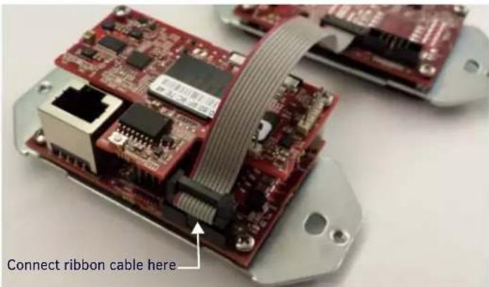
FIG. 21 Daisy-chained connection between the MET-7E and an Ethernet Expansion Keypad
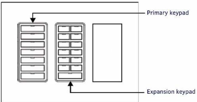
NOTE: If you are installing a single expansion keypad into a 3-gang back box, install the expansion keypad in the space immediately adjacent to the primary Ethernet keypad (see FIG. 22). Daisy-chaining is supported across a distance of 4" (101.6 mm).
flowchart
graph TD
    A["Primary keypad"] --> B["Block 1"]
    A --> C["Block 2"]
    D["Expansion keypad"] --> E["Block 3"]
    D --> F["Block 4"]
FIG. 22 Install the keypads immediately adjacent to each other in a 3-gang back box
NOTE: When the ribbon cable is connected, touching or moving the ribbon cable can cause a temporary disruption in communication causing the keypads to temporarily go offline and return to service shortly after the initial outset. Once the keypads are mounted and the ribbon cable is stable, no disruptions should occur.
Wiring and Connections
Overview
Some models of Metreau keypads support both AxLink and SWT wiring configurations. Each is described in the following subsections. For information on AxLink vs. SWT device addressing, refer to the AxLink Device Addressing section on page 24.
NOTE: Before touching the device, discharge the static electricity from your body by touching a grounded metal object.
Ethernet Wiring
Metreau Keypads with Ethernet and Metreau Ethernet Expansion Keypads use standard category cabling to provide power to the keypads. Applying power to the Metreau Keypads with Ethernet requires category cable and a PoE injector, such as the PS-POE-AF-TC (FG423-83) available from AMX. The network must be connected through the PoE injector to send power to the keypad. The category cable should only run through a common building. (A common building is defined as: Where the walls of the structure(s) are physically connected and the structure(s) share a single ground reference.)
Metreau Expansion Ethernet Keypads receive power from the Metreau Ethernet Keypad it is connected to via the 10-conductor ribbon cable on the expansion keypad.
Each Metreau keypad has a green LINK/ACTIVE LED on its rear panel that lights when the link is up and toggles off when a data packet is sent or received. Each Metreau keypad also has a green STATUS LED on its rear panel that is under firmware control. The following table lists the modes and blink patterns for the LINK/ACT and STATUS LEDs on the Metreau keypads:
| Modes and LED Blink Patterns | ||
| Description LINK/ACTIVE LED STATUS LED | ||
| Normal Online with Master (Rest) ON, if connected to a Master. Blinks OFF with data. | Follow Master's instruction for blink message if online with Master, otherwise ON | |
| Normal Boot (DHCP found) OFF ON | ||
| Normal Boot (DHCP, no server) Fast Blink, then normal operation ON | ||
| Normal Boot (Static IP) OFF, then normal operation (Off until connected to Master) | Fast Blink, then ON until first blink from Master | |
| Boot with ID pushbutton held down Slow Blink | Slow Blink | |
| ID pushbutton held down long enough for reset to default parameters | Fast Blink until ID pushbutton is released, then OFF | Fast Blink until ID pushbutton is released, then OFF |
| ID pushbutton held down long enough for reset to default firmware image | Solid ON, transitions to OFF once the unit completes writing to flash and is ready to reboot | Solid ON, transitions to OFF once the unit completes writing to flash and is ready to reboot |
| In Auto ID Mode | Normal | Blink |
| ID pushbutton held down long enough to accept new ID | 2 blinks, then normal | 2 blinks, then normal |
| After boot: ID pushbutton held down, but not long enough for IP mode change | Slow Blink Slow Blink | |
| After boot: ID Pushbutton held down long enough for IP mode change | Fast Blink, then OFF | Fast Blink, then OFF |
| Downloading Firmware to Flash Due to an upgrade via NetLinx Studio | Fast Blink, alternating with STATUS LED | Fast Blink, alternating with LINK/ACTIVE LED |
AxLink Wiring
In AxLink mode, Metreau keypads use a standard four-pin captive-wire AxLink connector for power and data.
CAUTION: If using power from AxLink, disconnect the wiring from the control system before wiring the Metreau keypad. Do not connect power to the keypads until the wiring is complete.
MET-6N, MET-7, and MET-13 Rear Panel Components
NOTE: Before touching the device, discharge the static electricity from your body by touching a grounded metal object.
FIG. 23 shows the basic rear components of the AxLink (MET-6N, MET-7, and MET-13) keypads:
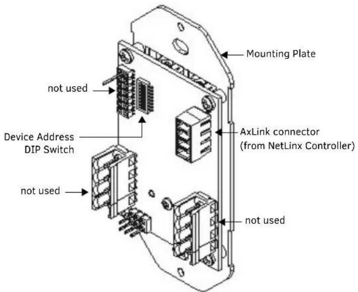
FIG. 23 MET-6SRC, MET-7 and MET-13 - Rear Components
AxLink Wiring Guidelines
Metreau keypads require 12 VDC power to operate properly. The necessary power is supplied via the AxLink cable. The maximum AxLink wiring distance is determined by power consumption, supplied voltage, and the wire gauge used for the cable. The following table lists wire sizes and the maximum lengths allowable based on the maximum power consumption rating of 170 mA.
| Wiring Guidelines at 170 mA | |
| Wire Size | Maximum Wiring Length |
| 18 AWG 690 | 42 feet (210.43 m) |
| 20 AWG 436 | 80 feet (133.13 m) |
| 22 AWG 272 | 33 feet (83.00 m) |
| 24 AWG 171 | 66 feet (52.32 m) |
The maximum wiring lengths for using AxLink power are based on a minimum of 13.5 volts available.
Preparing Captive Wires
You will need a wire stripper, and flat-blade screwdriver to prepare and connect the captive wires.
- Strip 0.25 inch (6.35 mm) of wire insulation off all wires.
- Insert each wire into the appropriate opening on the connector according to the wiring diagrams and connector types described in this section.
- Turn the flat-head screws clockwise to secure the wires in the connector.
NOTE: Do not over-torque the screws; doing so can bend the seating pins and damage the connector.
AxLink Data and Power Connections
Connect the NetLinx Controller's AxLink connector to the AxLink connector on the rear panel of the Metreau keypad for data and 12 VDC power as shown in FIG. 24.

flowchart
graph LR
    A["PWR (+)"] --> B["NetLinx Controller"]
    C["AXP"] --> B
    D["AXM"] --> B
    E["GNM (-)"] --> B
    B --> F["PWR (+)"]
    B --> G["AXP"]
    B --> H["AXM"]
    B --> I["GNM (-)"]
    style A fill:#f9f,stroke:#333
    style C fill:#f9f,stroke:#333
    style D fill:#f9f,stroke:#333
    style E fill:#f9f,stroke:#333
    style F fill:#ccf,stroke:#333
    style G fill:#ccf,stroke:#333
    style H fill:#ccf,stroke:#333
    style I fill:#ccf,stroke:#333
FIG. 24 AxLink straight-thru wiring
Using AxLink for Data with an Auxiliary Power Supply
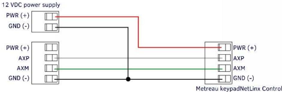
Use an auxiliary 12 VDC power supply when the distance between the controller and server exceeds the limits described in the AxLink Wiring Guidelines. Connect only the GND (-) wire on the AxLink connector when using an auxiliary 12 VDC power supply. Connect the NetLinx Controller's AxLink connector to the AxLink connector on the rear panel of the Metreau keypad, as shown in FIG. 25.
flowchart
graph LR
    A["PWR (+)"] --> B["GND (-)"]
    C["PWR (+)"] --> D["AXP"]
    E["AXM"] --> F["GND (-)"]
    B --> G["Metreau keypadNetLinx Control"]
    D --> G
    F --> G
    G --> H["PWR (+)"]
    G --> I["AXP"]
    G --> J["AXM"]
    G --> K["GND (-)"]
FIG. 25 AxLink and 12 VDC power supply wiring diagram
CAUTION: If you are not using power from AxLink, disconnect the wiring from the controller before wiring the Metreau keypad. Make sure the auxiliary power supply's PWR (+) is not connected to the controller's AxLink connector.
Orientation of AxLink Connectors
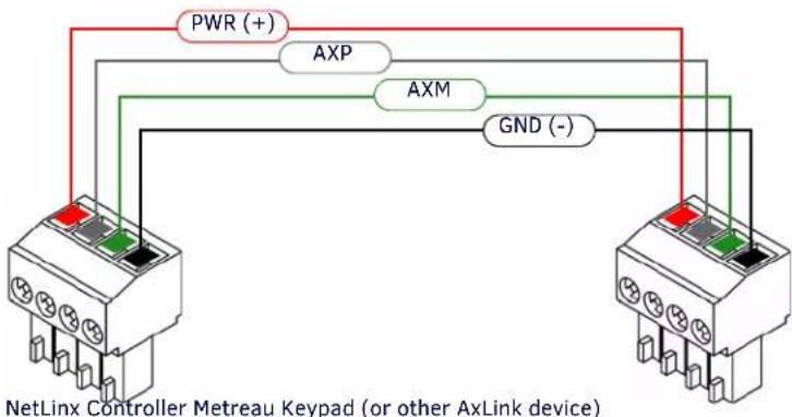
Note the orientation of the two AxLink 4-pin connectors; be sure to maintain straight-thru wiring as shown in the diagrams, relative to the connectors (FIG. 26):
flowchart
graph TD
    A["NetLinx Controller Metreau Keypad (or other AxLink device)"] --> B["AXP"]
    A --> C["AXM"]
    A --> D["GND (-)"]
    B --> E["PWR (+)"]
    C --> E
    D --> E
    E --> F["Red Signal"]
    E --> G["Green Signal"]
    E --> H["Black Signal"]
    E --> I["Red Signal"]
    E --> J["Green Signal"]
    E --> K["Black Signal"]
FIG. 26 AxLink wiring - orientation of the AxLink connectors
AxLink Status LED
The AxLink Status LED (located next to the AxLink connector), lights to indicate AxLink power/data status as follows:
| AxLink LED Status | |
| • 1 blink per second: Indicates power is active and AxLink communication is working. | |
| • Full On: Indicates the following conditions:• There is no AxLink control or activity, but power is On.• The Axcess program is not loaded. |
If the LED is on and not flashing, disconnect the AxLink connector and recheck all AxLink connections. Then, reconnect the AxLink connector to the panel and verify the LED is flashing once per second.
SWT Wiring
DAS-MET-6SRC and DAS-MET-7 Rear Panel Components
NOTE: Before touching the device, discharge the static electricity from your body by touching a grounded metal object.
FIG. 27 shows the basic rear components of the SWT (DAS-MET-6SRC and DAS-MET-NUM) keypads:
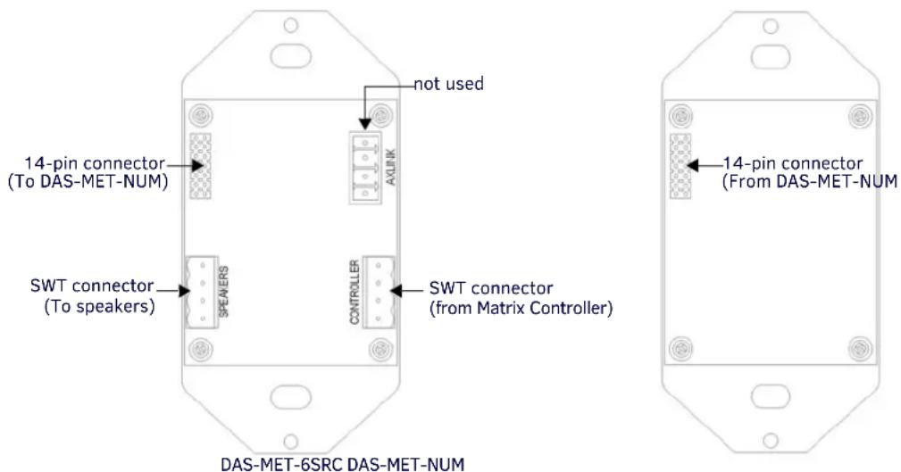
FIG. 27 DAS-MET-6SRC and DAS-MET-NUM - Rear Components
Cable Type
SWT wiring involves connecting the Mi-Series Controller, Metreau keypads, and speakers.
The Mi-Series Controller and Metreau keypads are cabled using standard four-conductor speaker cable originating at the Controller, passing through the keypad, and terminating at the speaker location.
AMX recommends using a bundled four-conductor 16-gauge stranded copper wire in a single continuous run.
Preparing Captive Wires
SWT wiring utilizes four-color "snap connectors" to secure the wires (no screws). You will need a wire stripper to prepare and connect the captive wires.
- Strip 0.25 inch (6.35 mm) of wire insulation off all wires.
- Insert each wire into the appropriate opening on the connector according to the wiring diagrams and connector types described in this section.
DAS-MET-6SRC - SWT Data and Power Connections
- Connect the Matrix Controller's Zone Output connector to the four-pin connector on the rear panel of the Metreau keypad labeled TO CONTROLLER for data and 12 VDC power.
- Connect the other four-pin connector on the keypad labeled TO SPEAKERS to the SWT speakers as shown in FIG. 24.
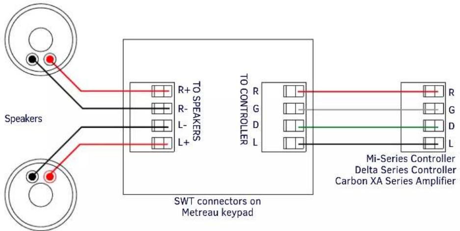
FIG. 28 SWT wiring
DAS-MET-NUM - Connecting to the Main DAS-MET-6SRC Keypad
The DAS-MET-NUM Metreau numeric keypad connects to the main DAS-MET-6SRC keypad via a 14-pin connector, as indicated in FIG. 29:
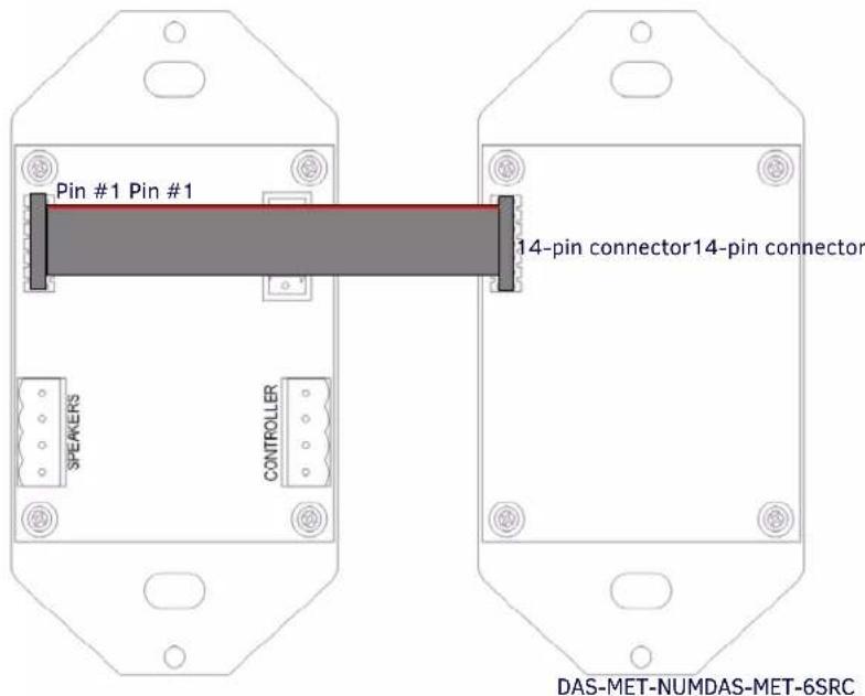
FIG. 29 DAS-MET-NUM connected to main DAS-MET-6SRC keypad
- The red line on the cable indicates Pin #1.
- The cable cannot be twisted, it must be straight across (Pin #1 to Pin #1).
Tango System Integration Drawings
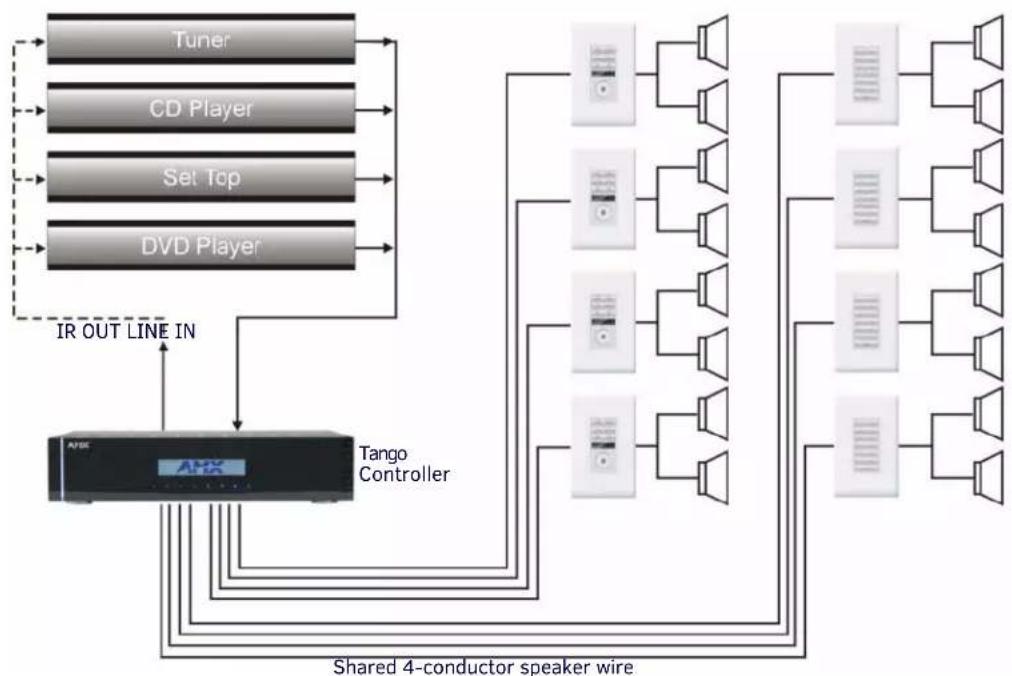
Tango System Integration Drawing - Using Four-Conductor Speaker Wire
flowchart
graph TD
    A["Tuner"] --> B["CD Player"]
    B --> C["Set Top"]
    C --> D["DVD Player"]
    D --> E["Tango Controller"]
    E --> F["Shared 4-conductor speaker wire"]
    F --> G["Speaker Array"]
    G --> H["Speaker Array"]
    H --> I["Speaker Array"]
    I --> J["Speaker Array"]
    J --> K["Speaker Array"]
    K --> L["Speaker Array"]
    L --> M["Speaker Array"]
    M --> N["Speaker Array"]
    N --> O["Speaker Array"]
    O --> P["Speaker Array"]
    P --> Q["Speaker Array"]
    Q --> R["Speaker Array"]
    R --> S["Speaker Array"]
    S --> T["Speaker Array"]
    T --> U["Speaker Array"]
    U --> V["Speaker Array"]
    V --> W["Speaker Array"]
    W --> X["Speaker Array"]
    X --> Y["Speaker Array"]
    Y --> Z["Speaker Array"]
    Z --> AA["Speaker Array"]
    AA --> AB["Speaker Array"]
    AB --> AC["Speaker Array"]
    AC --> AD["Speaker Array"]
    AD --> AE["Speaker Array"]
    AE --> AF["Speaker Array"]
    AF --> AG["Speaker Array"]
    AG --> AH["Speaker Array"]
    AH --> AI["Speaker Array"]
    AI --> AJ["Speaker Array"]
    AJ --> AK["Speaker Array"]
    AK --> AL["Speaker Array"]
    AL --> AM["Speaker Array"]
    AM --> AN["Speaker Array"]
    AN --> AO["Speaker Array"]
    AO --> AP["Speaker Array"]
    AP --> AQ["Speaker Array"]
    AQ --> AR["Speaker Array"]
    AR --> AS["Speaker Array"]
    AS --> AT["Speaker Array"]
    AT --> AU["Speaker Array"]
    AU --> AV["Speaker Array"]
    AV --> AW["Speaker Array"]
    AW --> AX["Speaker Array"]
    AX --> AY["Speaker Array"]
    AY --> AZ["Speaker Array"]
    AZ --> BA["Speaker Array"]
    BA --> BB["Speaker Array"]
    BB --> BC["Speaker Array"]
    BC --> BD["Speaker Array"]
    BD --> BE["Speaker Array"]
    BE --> BF["Speaker Array"]
    BF --> BG["Speaker Array"]
    BG --> BH["Speaker Array"]
    BH --> BI["Speaker Array"]
    BI --> BJ["Speaker Array"]
    BJ --> BK["Speaker Array"]
    BK --> BL["Speaker Array"]
    BL --> BM["Speaker Array"]
    BM --> BN["Speaker Array"]
    BN --> BO["Speaker Array"]
    BO --> BP["Speaker Array"]
    BP --> BQ["Speaker Array"]
    BQ --> BR["Speaker Array"]
    BR --> BS["Speaker Array"]
    BS --> BT["Speaker Array"]
    BT --> BU["Speaker Array"]
    BU --> BV["Speaker Array"]
    BV --> BW["Speaker Array"]
FIG. 30 System Integration Drawing Using Four-Conductor Speaker Wire
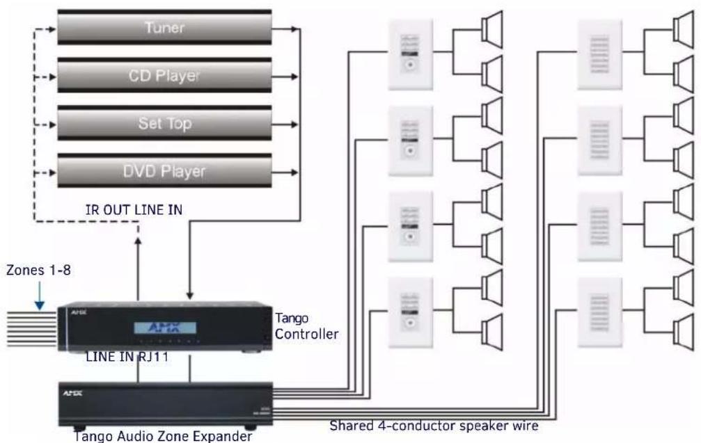
Tango System Integration Drawing - Using the Audio Zone Expander
flowchart
graph TD
    A["Tuner"] --> B["CD Player"]
    B --> C["Set Top"]
    C --> D["DVD Player"]
    D --> E["IR OUT LINE IN"]
    E --> F["Tango Controller"]
    F --> G["Shared 4-conductor speaker wire"]
    G --> H["Tango Audio Zone Expander"]
    H --> I["Zones 1-8"]
    I --> J["Line IN RJ11"]
    J --> K["Tango Controller"]
    K --> L["Shared 4-conductor speaker wire"]
    L --> M["Tango Controller"]
FIG. 31 System Integration Drawing Using the Audio Zone Expander
SWT Special Wiring Configurations
Auxiliary Amplifier Configuration
In some cases you may require more power for a given zone than the Matrix Controller can provide. You may purchase a DAS-LLC to provide a line level output to incorporate a larger external amplifier, or you can make your own line level converter. FIG. 32 shows the construction of a simple circuit of discrete components to reduce the "speaker level" output of the Matrix Controller to "line level" so that it can drive an auxiliary amplifier.
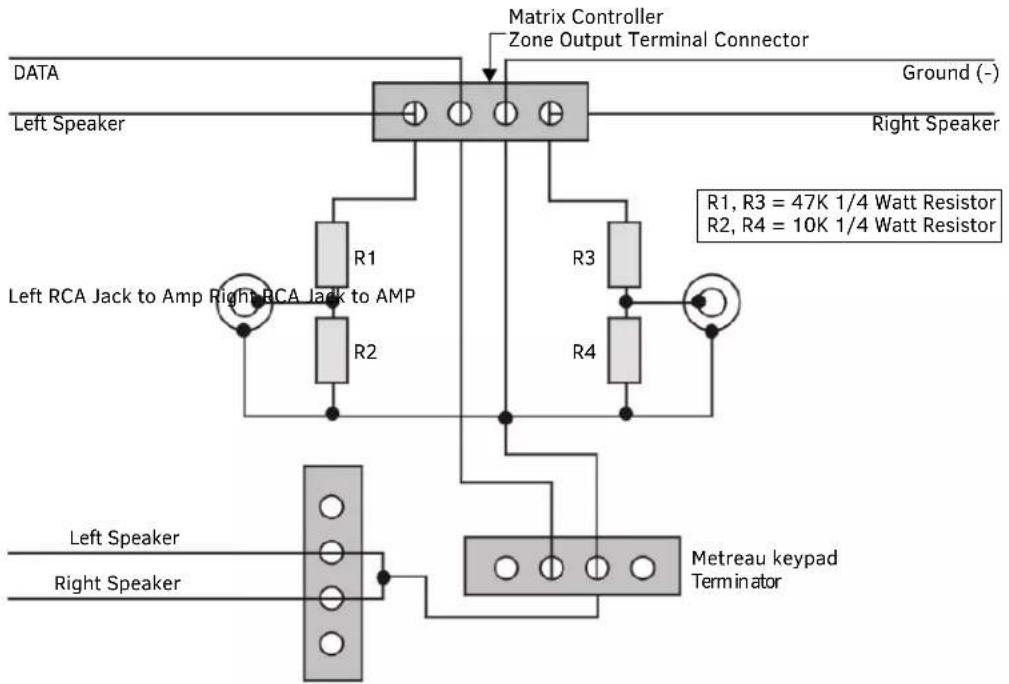
FIG. 32 Auxiliary Amplifier Configuration
This amplifier would typically be installed at the equipment rack (head end).
Remote Amplifier Configuration
In some cases, where the distance between the Matrix Controller and the zone is unusually long, it is sometimes desirable to have a remote amplifier at the zone end. You may install a DAS-LLC to accomplish this task or you may build your own. FIG. 33 shows the construction of a simple circuit of discrete components to reduce the Matrix Controller output to "line-level" so that it can be fed into an auxiliary amplifier.
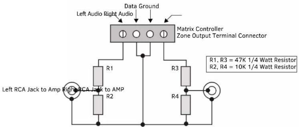
FIG. 33 Remote Amplifier Configuration
Two-Wire Configurations – Keypad for Control Only
In some retrofit configurations it is not feasible or possible to re-route the speaker cable through the keypad. In cases such as this, it is possible to run a separate cable pair (CAT-3 / CAT-5 / Twisted Pair) cable from the Matrix Controller to the keypad for control purposes. When using CAT3/CAT5 over long runs, it is recommended to "double-up" the control wires (only 2 conductors are required, and there are 4-8 wires available). FIG. 34 shows the connections of the control signal path to the keypad, and the speaker connections to the Matrix Controller.
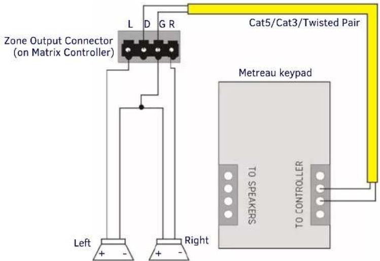
FIG. 34 2 Wire Configurations - keypad for Control Only
Split Zone / Analog Volume Control
In cases of split zones where more than one set of speakers are driven from the same keypad, it is sometimes desirable to place a volume control in the split zone. FIG. 35 shows the connections to a remote zone, and "Autoformer" volume control device.
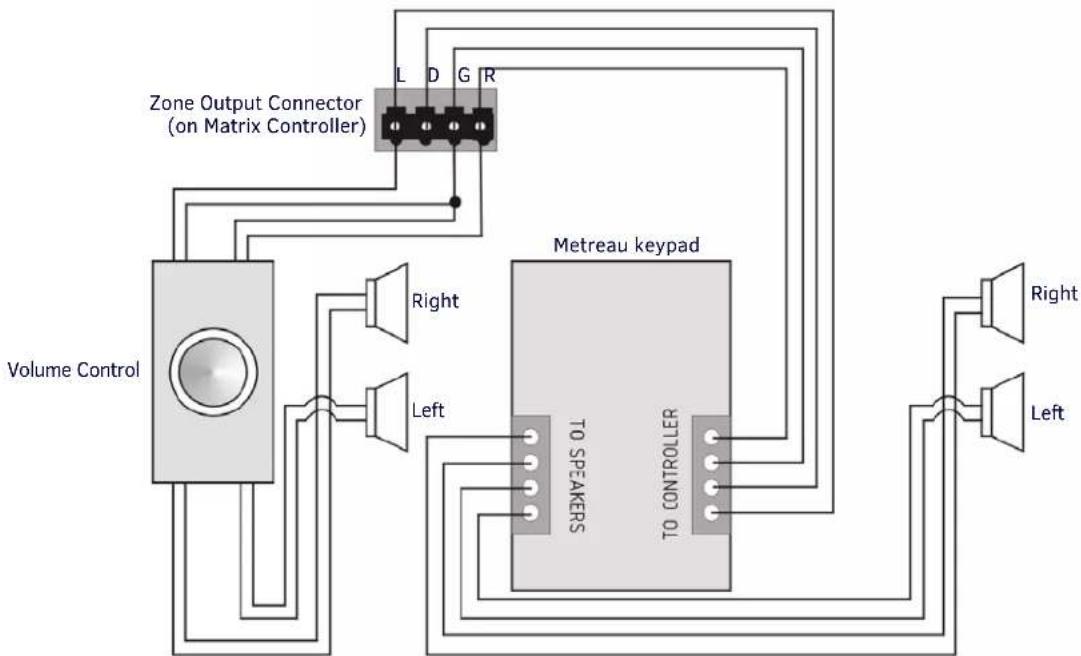
flowchart
graph TD
    A["Volume Control"] --> B["Zone Output Connector (on Matrix Controller)"]
    B --> C["Right"]
    B --> D["Left"]
    B --> E["Left"]
    B --> F["L D G R"]
    B --> G["TO SPEAKERS"]
    B --> H["70 GPIOLETH"]
    B --> I["Metreau keypad"]
    I --> J["Right"]
    I --> K["Left"]
FIG. 35 Split Zone / Analog Volume control (Option 2) one keypad
- Ensure the impedance setting doesn't fall below 4 Ohms.
- If you are installing 2 pairs of speakers in a zone and the speakers are 8 Ohms, it is not necessary to use an impedance matching autoformer type volume control. A standard stereo volume control will perform properly. The impedance will be approximately 4 Ohms.
- If you are using an impedance matching volume control with 2 pairs of speakers set the impedance matching to the 2X setting.
NOTE: It is not recommended to install more than 2 pair of speakers per zone.
Configuring Metreau Keypads with Ethernet
Overview
This chapter provides instructions on accessing and configuring the Metreau Keypads with Ethernet. To configure the keypad, you must have it powered by PoE.
Locating the IP Address of the Keypad
Metreau Keypads with Ethernet are configured for DHCP addressing by default. The keypads use link local addressing as a backup in case the DHCP server is inaccessible. See the Toggling Between IP Addressing Modes: DHCP and Static IP section on page 41 for information on setting a static IP address. Verify there is an active LAN connection on the controller's LAN port before beginning this procedure.
- Using category cable, connect the LAN port on the keypad to your external network.
- In NetLinx Studio, select the OnLine Tree tab. You should see the Metreau keypad listed among the Unbound Devices.
- Right-click the Metreau keypad and select Network Bind/Unbind Device from the menu that appears. The Bind/Unbind Device dialog opens.
- By default, the selected keypad appears in the Device to Bind/Unbind menu at the top of the dialog. If there is more than one Unbound device in the system, click the down arrow to select which device you want to bind.
- Select the check box next to the Master to which you want to bind the keypad. If there is more than one Master in the system, check the specific Master to which you want to bind the keypad.
- Click OK to save changes and close this dialog.
- Select Refresh System (in the Online Tree context menu). The device should now appear in the Bound Devices folder.
Simulating the ID Pushbutton
You can press buttons 1 and 2 simultaneously on the keypads to simulate the functions of a NetLinx device's ID pushbutton (see FIG. 36 for the button layout for each keypad).
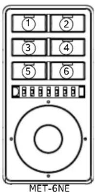
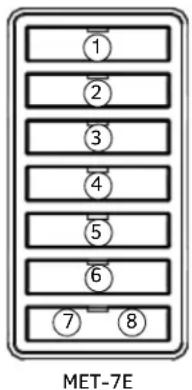
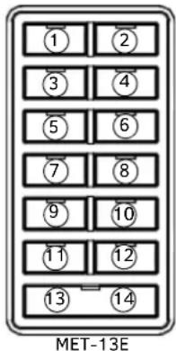
FIG. 36 Button layouts for Metreau Keypads with Ethernet
Toggling Between IP Addressing Modes: DHCP and Static IP
Metreau Keypads with Ethernet support both DHCP and static IP addresses. You can use a static IP address which you can set via a Telnet command (SET IP), or you can use the factory default static IP address (192.168.1.2).
With the keypad powered and booted up (or in ID Mode), you can toggle between the DHCP and Static IP modes by pressing and holding buttons 1 and 2. The LEDs on buttons 1 and 2 blink while you keep them pressed. Hold them until the LEDs begin blinking at double the rate (approximately 10 seconds), then release the buttons.
When you release the buttons, the keypad toggles either from static to dynamic (DHCP) IP addressing or vice versa and remains in that mode until the you use the buttons to toggle the IP mode again or you perform a factory reset. The keypad automatically reboots to complete the process.
NOTE: You must wait until the keypad is finished booting before toggling the IP address. Pressing the buttons while booting will cause the keypad to restore its factory default settings.
Assigning a Device ID to a Keypad
When used in conjunction with the ID Mode feature in NetLinx Studio, you can momentarily press buttons 1 and 2 on the keypad to assign a device address to the keypad. See the NetLinx Studio Instruction Manual or consult the online help tool in NetLinx Studio for more information.
Resetting the Keypad
To perform a factory reset of the Keypad, press and hold buttons 1 and 2 for approximately 10 seconds during the boot process. The LEDs on buttons 1 and 2 blink while you keep them pressed. Hold them until the LEDs begin blinking at double the rate (approximately 10 seconds.) Release the buttons and the keypad will reset. During factory reset, the backlight turns off for all buttons, but all buttons should be back online after 1-2 minutes. If you do not hold in the reset button until the LEDs begin blinking faster, the reset does not occur. (There is no soft reboot with the Reset button, but you can perform a soft reboot from the web pages.)
NOTE: When you reset a keypad, the keypad is restored to the factory default, so you will lose all configuration data as the defaults are restored.
Restoring the Factory Image on the Keypad
To restore the factory image on the keypad, press and hold buttons 1 and 2 for approximately 20 seconds during the boot process. The LEDs on buttons 1 and 2 blink slowly while you keep them pressed, and they begin to blink more quickly after 10-12 seconds. Hold the buttons until the LEDs stop blinking (approximately 20 seconds.) While pressing the buttons, disconnect and reconnect the cable from the LAN port on the rear panel of the device to restore the factory image firmware on the keypad.
Updating Firmware
Sending Firmware to Metreau Keypads (AxLink)
The Firmware on the AxLink-enabled Metreau keypads (MET-6N, MET-7 and MET-13) can be updated via the NetLinx Studio application.
Device Addressing on MET-6N Keypads
- The MET-6N uses two AxLink devices addresses - one for the keypad itself, and a second one for the IR Receiver.
- The device address of the IR Receiver is auto-assigned to be one number higher than the device address of the keypad itself (to which the firmware is uploaded).
- The MET-6N will appear as two devices in the Devices frame because it's built-in IR Receiver is recognized as a separate online device.
- Firmware is uploaded to the device address of the keypad (not the IR Receiver).
For example, if the MET-6N is set to device address 127, then the IR Receiver on that MET-6N will appear as device number 128. Firmware must be sent to the keypad, not the IR Receiver (in this example, device 127).
NOTE: Note: Refer to the NetLinx Studio online help for additional details on firmware transfers. NetLinx Studio is available for free download from www.amx.com.
-
Open NetLinx Studio.
-
Go to Tools > Firmware Transfers > Send to AxLink Device. The Send to AxLink Device dialog opens (FIG 37).
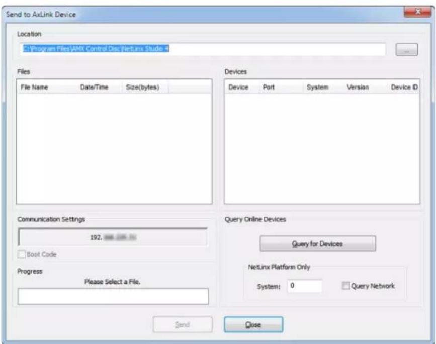
FIG. 37 Send to AxLink Device Dialog
- Browse to the location of the firmware file.
- Select the file within the Files area.
- Click Query for Devices.
- Select the Metreau keypad within the Devices area.
The MET-6N will appear as two devices in the Devices area because it's built-in IR Receiver is recognized as a separate online device.
The Device Address of the IR Receiver is always one number higher than the device number of the keypad itself (to which the firmware is uploaded). For example, if the MET-6N is set to device number 127, then the IR Receiver on that MET-6N will appear as device number 128. Firmware must be sent to the keypad, not the IR Receiver (in this example, device 127).
- Click Send. When NetLinx Studio has finished sending the firmware file to the keypad, you can click Close and then exit NetLinx Studio.
Sending Firmware to Metreau Keypads with Ethernet
The basic process of upgrading firmware on Metreau Keypads with Ethernet involves downloading the latest firmware files from www.amx.com and using NetLinx Studio to transfer the files to a target keypad.
NOTE: These steps assume that you have already established a connection with the target keypad in NetLinx Studio.
- In NetLinx Studio. click on the OnLine Tree tab (in the Workspace Bar) to view the devices on the System.
- In the OnLine Tree tab, click Display and select Refresh System from the context menu. Doing so establishes a new connection to the System and populates the device tree with devices on that system.
- After the Communication Verification dialog indicates active communication between the PC and the Central Controller, verify the Master and associated devices (including the Device Controller) are listed in the OnLine Tree.
- In NetLinx Studio, select Tools > Firmware Transfers > Send to NetLinx Device (FIG. 38):
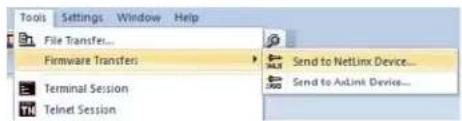
FIG. 38 NetLinx Studio - Tools > Firmware Transfers > Send to NetLinx Device
The Send to NetLinx Device dialog opens.
- Click the Browse button (...) to locate and select the firmware (*.kit) file that will be transferred, in the Browse for Folders dialog (FIG. 39):
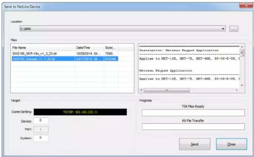
FIG. 39 Send to NetLinx Device dialog
The selected file is indicated in the Files window.
- Verify the target's System number matches the value listed within the active System folder in the OnLine Tree.
• The Device number is always 0 for the Master.
• Note that the Port field is disabled.
-
Click Send to begin the transfer. The file transfer progress is indicated in the Progress section of the dialog. The keypad reboots when the file transfer is complete.
-
Click Close once the keypad is finished rebooting.
- In the OnLine Tree, right-click on the Master and select Refresh System. This establishes a new connection and refreshes the device list and their firmware versions in your system.
Programming the SWT Metreau Keypads
SWT-only Metreau keypads (DAS-MET-6SRC and DAS-MET-NUM) are configured via options that are accessible through the Tango Audio Controller.
Refer to the Tango Audio Controller Operation/Reference Guide (available from www.amx.com) for details.
Programming
Programming the Metreau Keypads
Button Layouts
The following illustrations indicate the button numbers for each of the Metreau keypads (MET-6N, MET-6NE, MET-7, MET-7E, MET-7X, MET-13, MET-13E, and MET-13X):
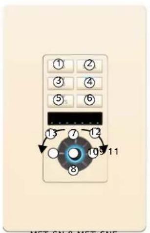
MET-6N & MET-6NE
Center pushbutton = button #11 dual function:
(push/release, press/hold)
rotate Navigation Wheel clockwise = button #12
rotate Navigation Wheel counter-clockwise = button #13
rotate Navigation Wheel CW/CCW = level #2
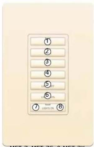
Bottom pushbutton is a two-position Pushbutton: left side = button #7 right side = button #8
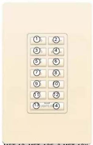
Bottom pushbutton is a two-position Pushbutton: left side = button #13 right side = button #14
FIG. 40 Button Layout - Metreau Keypads
Channels
Channels on Metreau keypads correspond to the button numbers on each keypad as indicated in FIG. 40.
Port Numbers
Metreau keypads with Ethernet support the following port numbers:
| Port Numbers | |
| Port Description | |
| 1 Metreau keypad with Ethernet | |
| 2 First daisy-chained keypad (optional) | |
| 3 Second daisy-chained keypad (optional) | |
| 4 | IR Receiver on MET-6NE. This port supports PUSH and RELEASE channels 1-255 for the received IR code. See the Device Addressing on MET-6N Keypads section on page 24 for information on determining the device address for the IR Receiver on the MET-6N. |
Programming the Navigation Wheel (MET-6N & MET-6NE)
The Navigation Wheel has multiple programming functions. The device has four buttons mounted underneath the wheel, assigned as top, bottom, left, right, and center. These buttons are fully programmable. The wheel itself is also fully programmable.
The Navigation Wheel on the MET-6N and MET-6NE can be treated from a NetLinx programming perspective as 5 distinct pushbuttons plus Channel up and down. The button layout for the Navigation Wheel is indicated below (FIG. 41).
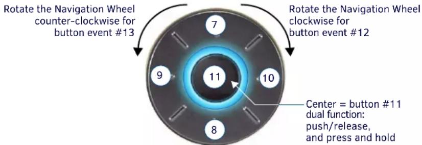
Rotate bi-directionally for level events on Level #2
FIG. 41 Navigation Wheel - button layout (MET-6N displayed)
Navigation Wheel - Buttons 7-11
The top, bottom, left, right and center points on the Navigation Wheel are pushbuttons that provide events on Channels #7, #8, #9, #10 and #11, and can be programmed like any other button.
Navigation Wheel - Buttons 12-13
The Navigation Wheel itself can be rotated clockwise and counterclockwise, and is intended to provide level control (for example volume or lighting levels).
- When rotated clockwise, the Navigation Wheel provides events on Channel #12.
- When rotated counter-clockwise, the Navigation Wheel provides events on Channel #13.
- When rotated (clockwise/counter-clockwise), the Navigation wheel provides level events on Level #2.
Navigation Wheel - Level Control
In addition to generating button events, a rotation of the wheel causes a level change on Level #2:
- Clockwise rotations increase the level
- Counter-clockwise rotations decrease the level.
Example code is provided below:
LEVEL_EVENT[dvMetreau,2]
{
    volume = level.value
    SEND_STRING 0, "Volume is now: ', ITOA(volume)"
}
Display Bargraph
The display bargraph consists of 7 LEDs and is controlled via Level #1. Sending a level will update the LEDs on the display bargraph. Example code is provided below:
SEND_LEVEL dvMetreau,1,200
Supported SEND\_LEVELs
MET-6N and MET-6NE keypads support a SEND_LEVEL on Level #1. This level is used to adjust the LED bargraph display on the keypad.
SEND_LEVELs
| SEND_LEVEL Adjusts the LED bargraph display on the keypad. | |
| Syntax: | |
| SEND_LEVEL,1, | |
| Variables: | |
| level = LED bargraph display (range = 0 - 255). | |
Supported SEND\_COMMANDs
The AxLink-enabled Metreau keypads (MET-6N, MET-7 and MET-13) and Metreau keypads with Ethernet (MET-6NE, MET-7E, and MET-13E) support a number of NetLinx SEND_COMMANDs, described in the following section. To use these commands, establish a Telnet session from the PC to the NetLinx master (see the Establishing a Terminal Connection via Telnet section on page 49 for more information.)
NOTE: All text is based on a Unicode index.
| SEND_COMMANDs | |
| Command Description | |
| @BRT | Set Brightness level for all LEDs (pushbuttons and levels indicator bar) for both On and Off states. Syntax:@BRT-,,Variables:on brightness = LED On brightness; ranges from 0 (off) to 32 (max).off brightness = LED Off level brightness; ranges from 0 (off) to 32 (max).Example:SEND_COMMAND keypad, '@BRT-32,0'Sets the LEDs to max brightness in the On state (32), and minimum brightness (no illumination) in the Off state (0). |
| @WBRT Set Brightness level for | Navigation Wheel LED, for both On and Off states.NOTE: This command is only valid on the MET-6N keypad. Syntax:'@WBRT-,,Variables:on brightness = Scroll Wheel LED on brightness; ranges from 0 (off) to 32off brightness = Scroll Wheel LED off brightness; ranges from 0 (off) to 32Example:SEND_COMMAND keypad, '@WBRT-32,0'Sets the Navigation Wheel LED to max brightness in the On state (32), and minimum brightness (no illumination) in the Off state (0). |
| BMODE Sets the bargraph mode | NOTE: This command is only valid on the MET-6E and MET-6NE keypads. Syntax:'BMODE-'Sets the specified bargraph to operate in one of the following modes:0 = (default) normal bar mode1 = normal dot mode (only one peak LED on at a time)2 = special bar mode (a level of 1-32 still has first LED on)3 = special dot mode (a level of 1-32 still has first LED on)4 = inverse normal bar mode5 = inverse normal dot mode6 = inverse special bar mode7 = inverse special dot mode8 = individual element, discrete mode9 = inverse individual element, discrete modeExample:SEND_COMMAND keypad, 'BMODE-0' |
| SEND_COMMANDs (Cont.) | |
| Command Description | |
| ?EXPANSION | Allows NetLinx code to query the keypad to determine whether any expansion keypads are attached to it. Syntax: ?EXPANSIONExample:SEND_COMMAND DEVICE_1, " ' ?EXPANSION' "Response Syntax:"Expansion-,,,,,,,"Variables:Index - response index, starting with 1Count - total number of response strings (i.e. max # of expansion keypads allowed, currently 2)Port - Port associated with the expansion keypadType - Expansion keypad type (either MET-7X or MET-13X)Description - Product descriptionExample Response Strings when a single expansion keypad is present:"Expansion.Device-1,2,2,MET-7X,Metreau 7-Button Expansion Keypad""Expansion.Device-2,2,3,NONE,NONE" |
| LED-DIS Disable LEDs on the keypad. | Syntax:LED-DISExample:SEND_COMMAND DEVICE_1," 'LED-DIS'"Disables LEDs on DEVICE_1.NOTE:This parameter does not get stored in non-volatile memory. LEDs are enabled by default at each power-up. |
| LED-EN Enable LEDs on the keypad. | LEDs are enabled by default. Syntax:LED-ENExample:SEND_COMMAND DEVICE_1," 'LED-EN'"Enables LEDs on DEVICE_1. |
| REBOOT Reboot the keypad. | Syntax:REBOOTExample:SEND_COMMAND DEVICE_1," 'REBOOT'"Reboots DEVICE_1. |
| SET_NDX_DESC Set Friendly name and location for NDP. | Syntax:Set_NDX_DESC-friendly name:locationMax of 25 characters for friendly name and max of 25 characters for location. If more than 25 characters are sent for either friendly name or location, they will be truncated to a max of 25 characters.Neither the friendly name nor the location should contain a ":" character, as that character is used as a delimiter.NOTE:This command requires a reboot to enable new settings. |
LED Feedback for 2-Position Pushbuttons
The Metreau 7- and 13-button keypads feature a 2-Position pushbutton at the bottom of the button layout (FIG 42). The button can be used either as a single button (in which case it functions just like the other buttons), or it can be used as a 2-position button. In many cases, this button is used as a 2-position button to provide ramp up/down control, for volume, light levels, etc.
- On Metreau 7-button keypads, the 2-Position button utilizes button numbers 7 (left-side) and 8 (right-side).
- On Metreau 13-button keypads, the 2-Position button utilizes button numbers 13 (left-side) and 14 (right-side).
Metreau 7-button Metreau 13-button
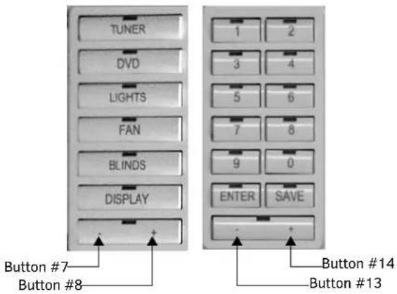
FIG. 42 MET-7 and MET-13 with 2-Position Button
NOTE: Only the left button provides LED feedback. To achieve LED feedback on the right button, you must toggle feedback on the left button.
Terminal (Telnet) Commands
Telnet terminal communication can be accessed remotely via TCP/IP.
Establishing a Terminal Connection via Telnet
- In your Windows task bar, go to Start > Run to open the Run dialog.
- Type cmd in the Open field and click OK to open an instance of the Windows command interpreter - "Cmd.exe" (FIG 43):
![Microsoft Windows [Version 6.1.7601] Copyright (c) 2009 Microsoft Corporation. All rights reserved. C:\Users\Icarey>](/content/2026/05/959638/images/09484885704acecb8ea3d669ec46f3fcfdc6ca90f75b6b3627f6a0d93c26f657.jpg)
FIG. 43 Windows command Interpreter (Cmd.exe)
- Type "telnet" followed by a space and the keypad's IP address:
>telnet XXX.XXX.XXX.XXX
- Press
.
- Without a Telnet password set, a session will begin with a welcome banner similar to the following:
Welcome to SP-08-E-US v1.0.44 Copyright AMX LLC >
- If a Telnet password is set, then user credentials are required:
Enter username:
Enter protected password:
Welcome to SP-08-E-US v1.0.44 Copyright AMX LLC
>
Telnet User Name and Password
There are two Telnet commands that set the Telnet user name and password:
- Set Telnet Username (see page 54)
- Set Telnet Password (see page 54)
By default, both the user name and password are blank (empty string). Performing a factory reset on the device will return these values to that default. See the Performing a Factory Reset section on page 18 for details.
- Setting the User Name will have no effect if the password remains blank (empty string). That is, defining the user name alone will not result in Telnet prompting for user login.
- Setting the Password will cause Telnet to prompt for user login, whether the user name has been defined or not. If the user name has been defined, this value must be entered.
However, since the password can be set independently of the user name, it's possible to have a password defined, but the user name still at its default (blank, empty string).
In this case, do not enter anything for the user name when prompted. Simply press
Additional Notes
- Both the Telnet user name and password are case-sensitive.
- Three consecutive, unsuccessful attempts to log in to Telnet will cause the Telnet window to close. Re-launching Telnet will again present the login prompt, with a fresh "batch" of login attempts.
- If Telnet login fails because of an incorrect user name, you will receive the "Invalid Password" message (as opposed to an "Invalid Username" message).
Setting a Telnet User Name and Password
To set a Telnet user name and password:
- Establish a terminal connection via Telnet.
- Type Set Telnet Username, and press
. The program will prompt you to enter a new Telnet user name. - Enter a user name and press
. The program will indicate that the user name is being stored. - Type Set Telnet Password, and press
.
NOTE: Press
- The program will prompt you to enter a password. Enter a password and press
. - The program will prompt you to re-enter the Telnet password. Re-enter the password and press
. The program will indicate that the password is being stored.
Telnet Commands
The commands listed in the following table can be sent directly to the EXB Module via a Telnet terminal session.
In your terminal program, type "Help" or a question mark ("?") and
| Terminal Commands | |
| Command Description | |
| ? or Help Display this list of commands. | |
| DEVICE STATUS | Display device status of a specified device, port, system ().Example:>device status 14021:1:1Device Status----Device 14021 AMX LLC, SP-08-E-US, v1.0.25 contains 1 Ports.Port 1 - Channels:8 Levels:1MaxStringLen=64 Types=8 bit MaxCommandLen=64 Types=8 bitThe following input channels are on:1,2,3,4The following output channels are on:NoneLevel 1=0 Supported data types=UByte,UInt> |
| EXIT Exit the telnet session | |
| FACTORYFWIMAGE Reset unit to factory firmware image and reboots the Module. | |
| Terminal Commands (Cont.) | |
| Command Description | |
| GET CONFIG Display the current connection settings. | |
| Example:>get configDevice number: 10001Connection Settings----ICSNet/Ethernet: EthernetMode: URLSystem Number: 1Master IP/URL: 192.168.1.211Master Port: 1319Username:Password:IP Settings----HostName: localhostType: DHCPIP Address: 192.168.1.53Subnet Mask: 255.255.255.0Gateway IP: 192.168.1.1MAC Address: 00:60:9f:94:2d:4fDNS Servers----Domain suffix: amx.internalEntry 1: 192.168.20.7Entry 2: 192.168.20.9NOTE:The system number and IP addressing information displayed is reflective of actual operating values, not stored parameters. | |
| GET CONNECTION Show the Module connection information. | |
| Example:>get connectionConnection Settings----ICSNet/Ethernet: EthernetMode: URL/TCPSystem Number: 1Master IP/URL: 192.168.1.211Master Port: 1319Username:Password: | |
| GET DEVICE Display the device number. | |
| GET DNS Get list of DNS entries. | Example:>get dnsDNS Servers----Domain suffix: amx.internalEntry 1: 192.168.20.7Entry 2: 192.168.20.9NOTE:When the module is in DHCP mode, these are active values, NOT the stored values that only apply to static mode. |
| GET ETHERNET MODE Display the current LAN configuration setting. | |
| Settings are either "auto" in which the LAN driver will discover it's settings based on the network it Is connected to ORandwhere speed is either 10 or 100 and duplex is either full or half.Example:>GET ETHERNET MODEEthernet mode is auto.NOTE:See the SET ETHERNET MODE command on page 53. | |
| GET FRIENDLYDisplays the Module's friendly name (for NDP).GET IP Displays the IP configuration of a device.The device displays it's D:P:S, host name, type (DHCP or Static), IP address, subnet mask, gateway IP, and MAC address.Example:>GET IF HostName MLK-INSTRUCTOR Type DHCP IP Address 192.168.21.101 Subnet Mask 255.255.255.0 Gateway IP 192.168.21.2 MAC Address 00:60:9f:90:0d:39 | |
| GET LOCATION | Displays the location parameter for NDP (set by the SET LOCATION command on page 54). |
| GET SN Returns the device's serial number | |
| INFO | Provides at-a-glance information about the keypad including any expansion keypads that are attached to it. |
| MSG [ON|OFF] Enables/Disables extended diagnostic messages.• MSG On [error|warning|info|debug] sets the terminal program to display log messages generated by the Master.The level of log printed to the terminal window depends both on the level used when sending the message and the output level selected with "msg on." For example if log output is enabled via "msg on warning" then logs produced at levels AMX_ERROR and AMX_WARNING will be displayed, but not logs produced at levels AMX_INFO or AMX_DEBUG.The order of severity from highest to lowest is ERROR, WARNING, INFO, DEBUG.If no severity is supplied with "msg on", the default setting is WARNING.• MSG OFF disables the display.Example:>MSG ON Extended diagnostic information messages turned on.>MSG OFF Extended diagnostic information messages turned off. | |
| NDP UNBIND Clears the NDP binding to a master (takes effect after next boot). | |
| PING [ADDRESS] | Pings an address (IP or URL), to test network connectivity to and confirms the presence of another networked device.The syntax matches the PING application in Windows or Linux.Example:>ping 192.168.29.209 192.168.29.209 is alive. |
| REBOOT Reboots the keypad. | Example:>REBOOTRebooting... |
| RENEW DHCP Renews/Releases the current DHCP lease for the keypad.Example:>RENEW DHCP | |
| RESET FACTORY | Resets the device's stored parameters to factory default state including removal of all security settings, resetting to DHCP.This command will cause an automatic reboot.NOTE: This command does not reset the device to the factory software image. |
| SET CONNECTION | Set the master connection settings interactively, allowing the user to specify the mode.• If mode is TCP or UDP, the master URL and port number can be specified as well.• If AUTO is selected, the System number can be specified.• After all data is entered, if the parameters have changed, the Module will disconnect from the Master, and begin trying to connect with the new settings.NOTE: These changes do not require a reboot to take effect. |
| SET DEVICE Set the device number, and store in non-volatile memory. Syntax: SET DEVICEThe valid range of device numbers is 0-31999.If the user enters a number outside that range, then no change will be made and the Module will issue an error message.A Device Number of '0' means that the Module will accept the auto-assigned device number from the Master.If the new device number is different from the old device number, the Module will disconnect from the Master, and begin trying to connect with the new settings.NOTE: These changes do not require a reboot to take effect. | |
| SET DNS | Set the DNS configuration of the EXB Module, only as applied to Static IP addressing mode (DNS settings in DHCP mode are received from the DHCP server).Syntax: SET DNSThis command prompts you to enter a Domain Name, DNS IP #1, DNS IP #2, and DNS IP #3.Enter Y (yes) to approve/store the information in the Master.Enter N (no) cancels the operation.NOTE: The device must be rebooted to enable new settings.Example:>SET DNS [0:1:0]-- Enter New Values or just hit Enter to keep current settings --Enter Domain Suffix: amx.comEnter DNS Entry 1 : 192.168.20.5Enter DNS Entry 2 : 12.18.110.8Enter DNS Entry 3 : 12.18.110.7You have entered: Domain Name: amx.comDNS Entry 1: 192.168.20.5DNS Entry 2: 12.18.110.8DNS Entry 3: 12.18.110.7Is this correct? Type Y or N and Enter -> YSettings written. Device must be rebooted to enable new settings |
| SET ETHERNET MODE | This command sets the current LAN configuration settings per new mode Syntax: SET ETHERNET MODE<newmode>Values for newmode are:auto-or-10 | 100 full | halfNOTE: This command requires a reboot to enable new settings.Examples:set ethernet mode autoset ethernet mode 100 fullNOTE: See the GET ETHERNET MODE command on page 51. |
| SET FRIENDLY Set the device's friendly name for NDP to.<name>. Syntax: SET FRIENDLY<name>Maximum length = 25 characters. If the name entered exceeds 25 characters, it will be truncated.The value is stored in non-volatile memory.If no value specified, an automatic name consisting of AMX, the product name, and serial number will be used.NOTE: Note: This command requires a reboot to enable new settings. | |
| SET IP Sets the IP configuration of a specified device.Enter a host name, type (DHCP or Fixed), IP address, subnet mask, and gateway IP address.NOTE: “DHCP” implies “DHCP with link-local fallback”.NOTE: For NetLinx Masters, host names may contain only the ASCII letters 'a' through 'z' (in a case-insensitive manner), the digits '0' through '9', and the hyphen (-').• Enter Y (yes) to approve/store the information into the Master.• Enter N (no) to cancel the operation.NOTE: This command requires a reboot to enable new settings.Example:>SET IP--- Enter New Values or just hit Enterto keep current settings ---Enter Host Name: MLK_INSTRUCTOREnter IF type. Type D for DHCP or S for Static IP andthen Enter: DHCPEnter Gateway IP: 192.168.21.2You have entered: Host Name MLK_INSTRUCTORType DHCPGateway IP 192.168.21.2Is this correct? Type Y or N and Enter -> ySettings written. Device must be rebooted to enable new settings.NOTE: Metreau keypads can also be set to Static IP or DHCP Mode by using the ID Pushbutton.See the Toggling Between IP Addressing Modes: DHCP and Static IP section on page 41 for details. | |
| SET LOCATION Sets the location para meter for NDP.Syntax:SET LOCATION• Maximum length = 25 characters. If the name entered exceeds 25 characters, it will be truncated.NOTE: This command requires a reboot to enable new settings. | |
| SET TELNET PORT Sets the device's IP port listened to for Telnet connections.Example:>SET TELNET PORTCurrent telnet port number - 23Enter new telnet port number (Usually 23) (0=disable Telnet):Once you enter a value and press, you get the following message:Setting telnet port number to 23New telnet port number set, reboot the device for the change to take effect.NOTE: This command requires a reboot to enable new settings.See the Enabling/Disabling Telnet on the Keypad section on page 55 for additional information. | |
| SET TELNET USERNAME Set the user name for a secure Telnet session.• Default = blank (no user name required)• See the Setting a Telnet User Name and Password section on page 50 for details. | |
| SET TELNET PASSWORD Set the Password for a secure Telnet session.• Default = blank (no password required)• See the Setting a Telnet User Name and Password section on page 50 for details. | |
| SHOW CONNECTION LOG Show the master connection log for the device | |
| SHOW CONNECTION STATS Show the connection statistics for the device.Output similar to the following example:>show connection statsConnection StatisticsTotal Last 15 MinutesICSP Messages: 10039 received 333 received10038 transmitted 333 transmittedBlink Messages: 5014 received 166 receivedIF Statistics:RX packets:29298 errors:0 discarded:0TX packets:15286 errors:0 discarded:0 | |
| SHOW LOG Display the message log. | Syntax:SHOW LOGto specify the message number to start displayingUseto display all messages. |
Notes on Specific Telnet Clients
Telnet and terminal clients will have different behaviors in some situations. This section states some of the known anomalies.
Windows Client Programs
Anomalies occur when using a Windows™ client if you are not typing standard ASCII characters (i.e. using the keypad and the ALT key to enter decimal codes). Most programs will allow you to enter specific decimal codes by holding ALT and using keypad numbers.
For example, hold ALT, hit the keypad 1, then hit keypad 0, then release ALT. The standard line feed code is entered (decimal 10). Windows will perform an ANSI to OEM conversion on some codes entered this way because of the way Windows handles languages and code pages.
The following codes are known to be altered, but others may be affected depending on the computer's setup.
Characters 15, 21, 22, and any characters above 127.
This affects both Windows Telnet and Terminal programs.
Linux Telnet Client
The Linux Telnet client has three anomalies that are known at this time:
- A null (\00) character is sent after a carriage return.
- If an ALT 255 is entered, two 255 characters are sent (per the Telnet RAFT).
- If the code to go back to command mode is entered (ALT 29 which is ^]), the character is not sent, but Telnet command mode is entered.
Enabling/Disabling Telnet on the Keypad
By default, Telnet is enabled on all Metreau keypads. The default Telnet port is 23.
You can change the Telnet port by using the SET TELNET PORT command (see page 54). Setting the Telnet port to zero disables Telnet access.
The SET TELNET PORT command requires a reboot to enable new settings.
NOTE: The only way to re-enable Telnet once it has been disabled is to reset the unit to the factory default firmware image. See the Restoring the Factory Image on the Keypad section on page 42 for details.
Basic Keypad Functions - DAS-MET-6SRC
Overview
Metreau Keypads are pre-configured to provide many common functions. The DAS-MET-6SRC provides basic keypad functionality, including Source Control (selecting source, initiating and pausing playback), Volume control (Up/Down), Zone control (On/Off), and audio (Bass/Treble/Balance/SRS Mode) adjustment.
NOTE: The SWT Metreau keypads function essentially the same as previous versions SWT keypads.
The standard configuration for the Audio (SWT) 6-Source Keypad (DAS-MET-6SRC) is described below. Note that while the functionality described here is fixed for the SWT Keypads, the AxLink Keypads can be customized, just like any other AxLink keypad.
DAS-MET-6SRC - Listening to a CD or DVD
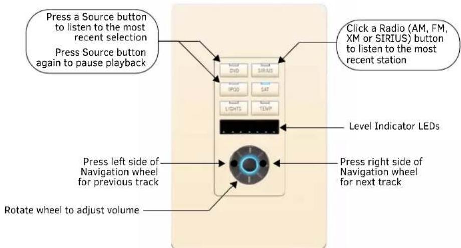
FIG. 44 Metreau Audio keypads
Selecting the Source for Playback
Press the source button (i.e. "CD" or "DVD") on the room/zone keypad to listen to the most recent selection.
- If the Source is off the system will turn it on.
- If the Source is stopped the system will initiate Play.
- If the Source has been paused or muted, the system will un-pause / un-mute it.
Changing Tracks
- Press the left and right sides of the Navigation Wheel to change tracks.
- Press the button in the center of the Navigation Wheel to select a track and initiate playback.
Pausing Playback
To Pause playback, press the button of the source that is currently playing (indicated by an active LED).
- The CD/DVD is only paused if there are no other zones listening to that source. If no other zones are listening to that source it will be paused.
- If the source remains paused for greater than 10 minutes, the Controller will send a POWER OFF command to the source.
Listening to an iPod
Dock the iPod in the docking station connected to the Tango Audio Controller, and press the iPod button on the room/zone keypad to listen to the most recent selection.
The UP, DOWN, LEFT, RIGHT, Centre PRESS and Centre HOLD buttons are programmed by the installer, based on what the individual dock with remote can do. For example, UP/RIGHT could both be programmed to be Next track, DOWN/LEFT could both be programmed to be to be Previous track, and Centre could be programmed to be Play/Pause.
Listening to the Radio
- Press the AM, FM, SIRIUS or XM button on the room/zone keypad to listen to the most recent station.
- Select a new station by pressing a custom-programmed button.
The UP, DOWN, LEFT, RIGHT, Centre PRESS and Centre HOLD buttons are programmed by the installer, however, the standard configuration for the AM/FM Tuner, and for the SIRIUS/XM Tuner is as follows:
AM/FM Tuner on a 6-source keypad:
• UP/DOWN = Seek Up/Down
• LEFT/RIGHT = Prev/Next Preset
• Centre Press = Toggle AM/FM
• Centre Hold = Toggle Stereo/Mono
SIRIUS/XM Tuner on a 6-source keypad:
• UP/DOWN = Channel UP/DOWN
• LEFT/RIGHT = Category Next/Prev
- Centre = Select
- Centre Hold = Menu
On a Numeric keypad:
- Select a new station by pressing the station's call numbers on the DAS-MET-NUM Numeric keypad.
Adjusting the Volume
The Navigation Wheel can be rotated bi-directionally, and provides volume level control.
- Clockwise rotation increases the volume level, counter-clockwise rotation decreases the volume level.
- When the volume is increased/decreased, the 7 LEDs on the KP will increase/decrease accordingly.
- Volume is changed based on angle rotation. Each quarter turn is approximately +/- 3db. The range for Volume is 0-70.
DAS-MET-6SRC - Audio Adjustment Mode
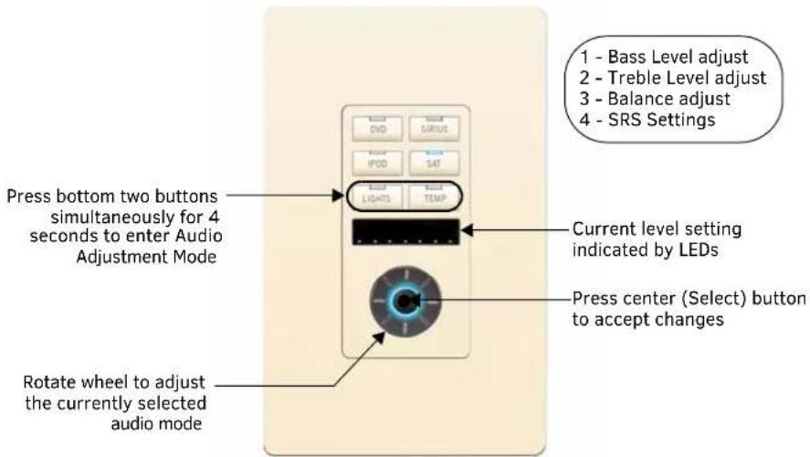
FIG. 45 DAS-MET-6SRC
On a 6-source keypad, press and hold the bottom two Source buttons simultaneously for four seconds to set or adjust Bass, Treble, Balance and SRS Mode settings in that room/zone.
Adjusting Bass Level For a Room/Zone
When the bottom two Source buttons are pressed simultaneously for four seconds, the first adjustment is for Bass Level:
- The top-left LED will blink to indicate that Bass Level Adjustment mode is active (FIG. 46).
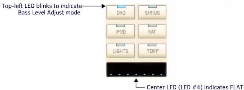
FIG. 46 Bass Level Adjust Mode
- Rotate the Navigation Wheel to adjust the bass level up (clockwise) or down (counter-clockwise).
NOTE: Bass adjustments are provided in +/- 1dB steps, from -10dB (min) to +10dB (max). - The bass level is indicated in the LED display: Flat = center LED (#4) lit.
- Press and hold the center (Select) pushbutton on the Navigation Wheel for 3 seconds to return to the default Bass Level setting.
Press the center (Select) pushbutton on the Navigation Wheel to set the current bass level, and proceed to Treble Adjustment mode.
Adjusting Treble Level For a Room/Zone
When the Bass Level is set (via the Select button - see above), the next adjustment is for Treble Level:
- The top-right LED will blink to indicate that Treble Adjustment mode is active (FIG. 47).
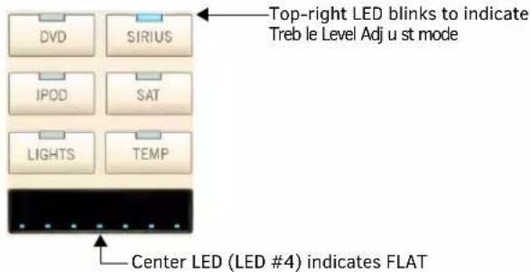
FIG. 47 Treble Level Adjust Mode
- Rotate the Navigation Wheel to adjust the treble level up (clockwise) or down (counter-clockwise).
NOTE: Note: Treble adjustments are provided in +/- 1dB steps, from -10dB (min) to +10dB (max). - The treble level is indicated in the LED display: Flat = center LED (#4) lit.
- Press and hold the center (Select) pushbutton on the Navigation Wheel for 3 seconds to return to the default Treble Level setting.
Press the center (Select) pushbutton on the Navigation Wheel to set the current treble level, and proceed to Balance Adjustment mode.
Adjusting Balance For a Room/Zone
When the Treble Level is set (via the Select button - see above), the next adjustment is for Balance Adjust:
- The middle-row left LED will blink to indicate that Balance Adjust mode is active (FIG. 48).
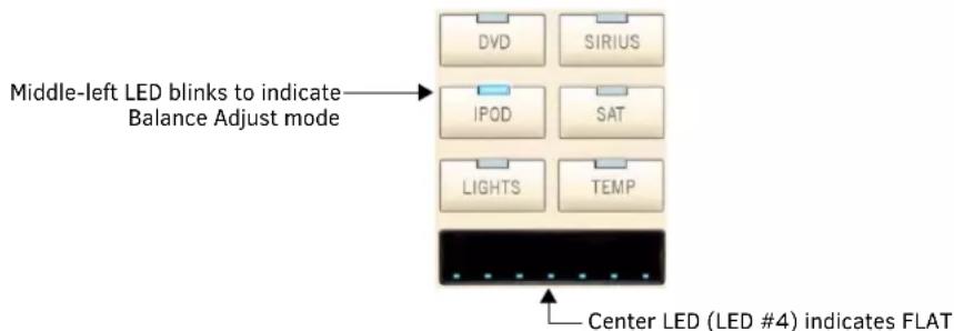
FIG. 48 Balance Adjust Mode
- Rotate the Navigation Wheel to adjust the balance right (clockwise) or left (counter-clockwise).
- The balance setting is indicated in the LED display: Flat = center LED (#4) lit.
- Press and hold the center (Select) pushbutton on the Navigation Wheel for 3 seconds to return to the default Balance setting.
Press the center (Select) pushbutton on the Navigation Wheel to set the current balance settings, and proceed to SRS Adjustment mode.
Adjusting SRS Settings For a Room/Zone
When the Balance setting is set (via the Select button - see above), the next adjustment is for SRS Adjust:
- The second-row right LED will blink to indicate that SRS Adjust mode is active (FIG. 49).
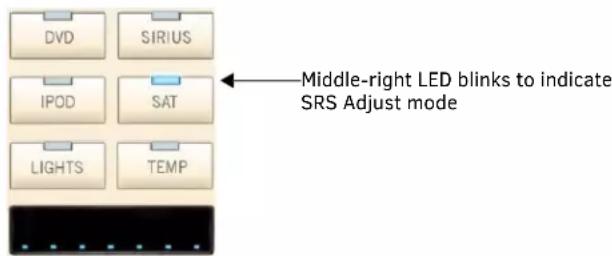
FIG. 49 SRS Adjust Mode
- Rotate the Navigation Wheel to select the desired SRS mode.
Press the center (Select) pushbutton on the Navigation Wheel to set the current SRS settings, and proceed to LED "ON" Brightness Adjust mode.
Turning SRS Off
Press and hold the Center Navigation button while in SRS mode.
DAS-MET-6SRC - Privacy Mode Off/On
When Privacy Mode is engaged, the room/zone cannot be paged, apart from this, the room/zone will function normally.
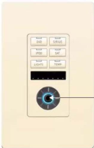
With all Sources OFF, press and hold the center Select button for 4 second to turn on Privacy Mode in this zone.
FIG. 50 Privacy Mode Off/On
NOTE: To use Privacy Mode in a specific zone, the keypad must be OFF (no sources selected).
To engage Privacy Mode, press and hold the Select button (the center pushbutton on the Navigation Wheel) for 4 seconds. All Source buttons will glow & pulse at a low level to indicate Privacy mode is active.
Turning Off Privacy Mode
To disengage Privacy Mode, turn on the zone by pressing any one of the source buttons.
Working with Sources
When a Source button is selected, the following occurs:
The Source is turned ON, and if there is a Favorite assigned for the Source, then the favorite begins playing. If no Favorite has been set for the Source, the following occurs:
- If the Source is the on-board Tuner, the first Preset will begin playing. If there are no Presets, then the last station listened to will begin playing.
- If the Source is an external Tuner, the last station listened to will begin playing.
- If the Source is a CD player/changer, the first Track of the first CD will begin playing (unless the source has the ability to retain its previous settings).
- If the Source is Satellite, then the last station listened to will begin playing.
NOTE: Note: For information on assigning a Favorite to a Source, refer to the Creating a Favorite for a Specific Source section on page 69. For information on assigning a Preset to a Tuner, refer to the Creating a Preset section on page 68.
DAS-MET-6SRC - Zone Control (On/Off)
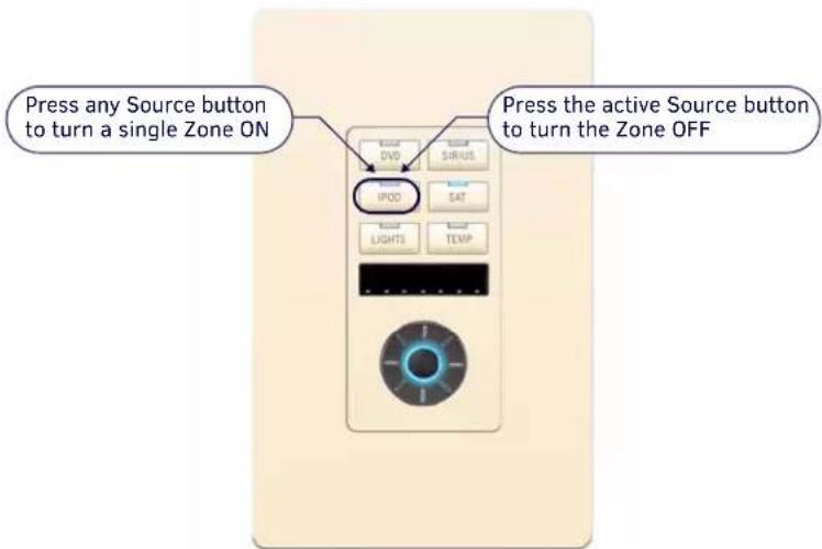
FIG. 51 Zone Control (On/Off)
Turning a Single Zone On/Off
- To turn a single Zone ON, press any Source Button.
- To turn a single Zone OFF, press the Active Source Button.
Turning On a Source in All Zones
Press and hold any Source Button for a duration of 4 seconds (the selected Source will play in all zones).
Turning Off/On a Source in All Zones
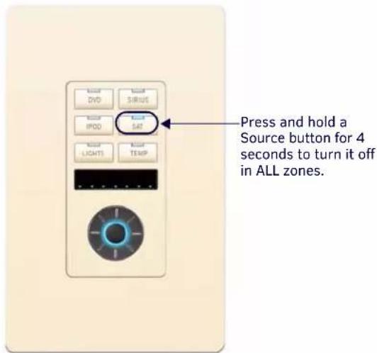
FIG. 52 Turning Off a Specific Source in All Zones
Press and hold the active Source button for 4 seconds to turn it off in all zones. To turn the source back on in all zones, press and hold the same Source button for 4 seconds.
Turning Off All Zones (System OFF)
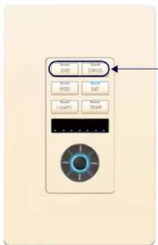
-Press and hold the top two Source buttons to turn ALL sources off in ALL zones.
FIG. 53 Turning Off all Sources in All Zones
Press and hold the top two Source buttons simultaneously for 4 seconds.
NOTE: All zones will be turned off, and no sources will play. One minute after an ALL OFF has been performed, all sources will power down and the Controller will Default to "Standby Mode".
DAS-MET-6SRC - Zone Control (Dynamic Pause)
Switching sources within a single zone, turning off an active source within a single zone, and switching sources for all (grouped) dynamically pauses the source device that is no longer being used.
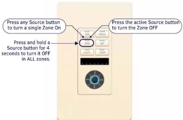
FIG. 54 Turning Off All Zones
Single Zone Listening To Source
Switching sources, or turning off the Source for a single Zone dynamically pauses the Source:
- With a single Zone listening to a Source, switching to a different Source dynamically pauses the original Source, and begins playing the newly selected Source.
- With a single Zone listening to a Source, turning off the Source dynamically pauses the Source.
Multiple Zones Listening To The Same Source
Switching Sources, or turning off the Source for one Zone does not dynamically pause the Source:
- With multiple Zones listening to the same Source, switching to a different Source from one of the Zones does not pause the original Source, and the original Source continues to play in all other Zones that are On.
- With multiple Zones listening to the same Source, turning off the Source for one zone does not dynamically pause Source, and the original Source continues to play in all other Zones that are On.
Single or Multiple Zones Listening To The Same Source
Grouping all Zones to another Source, dynamically pauses the Source:
- With single or multiple Zones listening to the same Source, grouping all Zones from another Zone using a different Source dynamically pauses the original Source.
DAS-MET-6SRC - Using the Navigation Wheel
The Navigation Wheel on the DAS-MET-6SRC provides multiple functions, based on the source type selected, as described in the following sections:
Using the Navigation Wheel with the Internal AM/FM Tuner
FIG. 55 describes the functions available at the Navigation Wheel, when using the internal AM/FM Tuner:
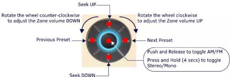
FIG. 55 Using the Navigation Wheel With The Internal AM/FM Tuner
Using the Navigation Wheel with the Internal SIRIUS Tuner
FIG. 56 describes the functions available at the Navigation Wheel, when using the internal SIRIUS Satellite Radio Tuner:
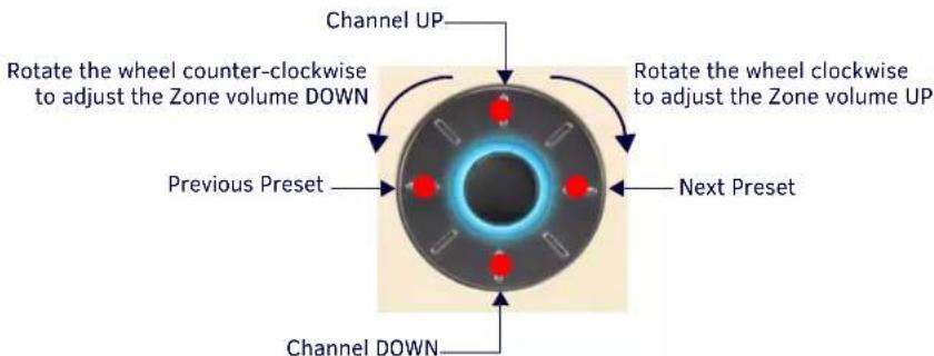
FIG. 56 Using the Navigation Wheel With The Internal SIRIUS Satellite Radio Tuner
Using the Navigation Wheel with a CD Player/Changer
FIG. 57 describes functions available at the Navigation Wheel, when used with a CD Player/Changer:
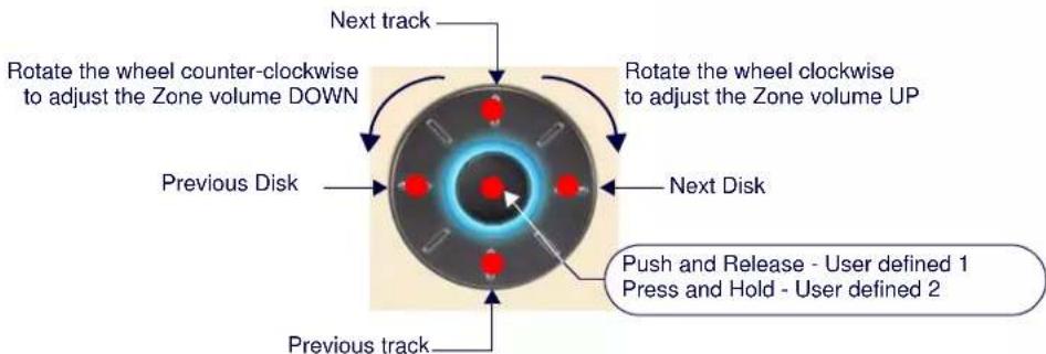
FIG. 57 Using the Navigation Wheel With CD Player/Changer
NOTE: These are suggested settings. All buttons are user-definable.
Using the Navigation Wheel with a DVD Player/Changer
FIG. 58 describes functions available at the Navigation Wheel, when used with a DVD Player/Changer:
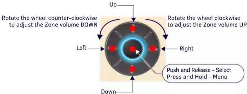
FIG. 58 Using the Navigation Wheel With DVD Player/Changer
NOTE: These are suggested settings. All buttons are user-definable.
Using the Navigation Wheel with a Satellite Radio/Video Box
FIG. 59 describes functions available at the Navigation Wheel, when used with a DVD Player/Changer:
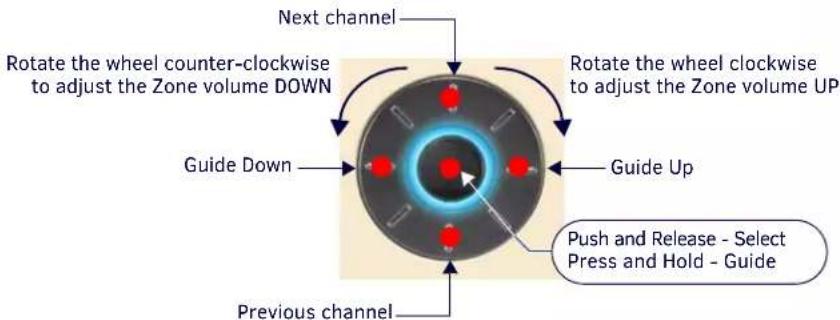
FIG. 59 Using the Navigation Wheel With Satellite Radio/Video Box
NOTE: These are suggested settings. All buttons are user-definable.
Using the Navigation Wheel with an Audio Server
FIG. 60 describes functions available at the Navigation Wheel, when used with an Audio Server:
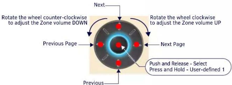
FIG. 60 Using the Navigation Wheel With Audio Server
NOTE: These are suggested settings. All buttons are user-definable.
Using the Navigation Wheel with an External Tuner
FIG. 61 describes functions available at the Navigation Wheel, when used with an External Tuner:
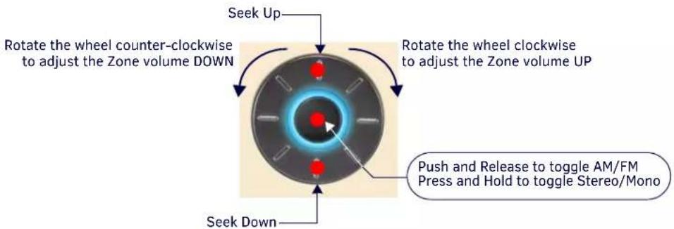
flowchart
graph TD
    A["Seek Up"] --> B["Rotate the wheel counter-clockwise to adjust the Zone volume DOWN"]
    B --> C["Rotate the wheel clockwise to adjust the Zone volume UP"]
    C --> D["Push and Release to toggle AM/FM Press and Hold to toggle Stereo/Mono"]
    D --> E["Seek Down"]
FIG. 61 Using the Navigation Wheel With External Tuner
NOTE: These are suggested settings. All buttons are user-definable.
Using the Navigation Wheel with Other Sources
FIG. 61 describes functions available at the Navigation Wheel, when used with other sources:
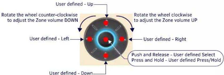
FIG. 62 Using the Navigation Wheel With Other sources
NOTE: These are suggested settings. All buttons are user-definable.
Advanced Functions - DAS-MET-6SRC
Overview
The DAS-MET-NUM Numeric keypad is used in conjunction with the DAS-MET-6SRC keypad to provide enhanced functionality, including Direct Numeric Access, Zone Grouping, Favorites, Alarm (setting), Keypad Lockout and setting and recalling Presets.
NOTE: The SWT Metreau Keypads function essentially the same as previous versions SWT keypads.
The standard configuration for the Audio (SWT) Keypads (DAS-MET-6SRC and DAS-MET-NUM) is described below. Note that while the functionality described here is fixed for the SWT Keypads, the AxLink Keypads can be customized, just like any other AxLink keypad.
Direct Access
On-Board Tuner - Direct Selection of a Radio Station
Using the DAS-MET-NUM keypad, enter the station identification and press ENTER.
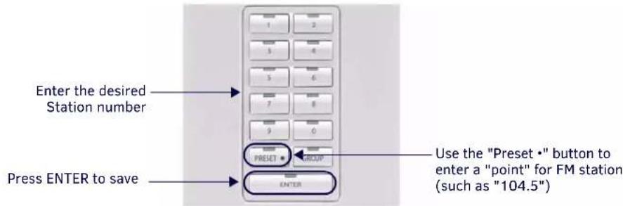
FIG. 63 Direct Selection of a Radio Station
-
Key in the Station identifier number using the "PRESET" button to enter a "point" for FM stations.
-
Press ENTER to complete.
NOTE: Strings of 3 to 4 numbers are recognized. If a “•” (point) is part of the string, then an FM station is assumed, otherwise an AM station is assumed.
Examples:
• 1050 + ENTER = 1050AM
• 104·5 + ENTER = 104.5FM
- 88·8 + ENTER = 88.5FM
CD Player - Direct Selection of a Disk and Track
To select a specific disk and track, the format is DDD·TTT + ENTER (DDD = Disk & TTT = Track).
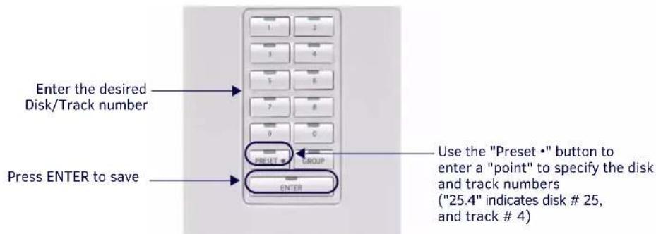
FIG. 64 Direct Selection of a Disk and Track
- Enter the Disk number.
- Press the "PRESET" button.
- Key in the Track number (for example, "25.4" indicates CD # 25, Track #4).
- Press ENTER to complete.
Examples:
- 52·3 + ENTER = Disk 52, Track 3
• 1·22 + ENTER = Disk 1, Track 22
• 103·2 + ENTER = Disk 103, Track 2
CD Player - Direct Selection of a Track on the Current Disk
To select a specific track on the current disk, enter TTT + ENTER (TTT=Track).
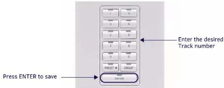
FIG. 65 Direct Selection of a Track On the Current Disk
To change the track while listening to a disk:
- Key in the Track number.
- Press Enter to complete.
Examples:
• 3 + ENTER = current disk, Track 3
• 19 + ENTER = current disk, Track 19
Cable and Satellite - Direct Selection of a Channel
To select a channel on a Cable or Satellite receiver, the format is CCC + ENTER (CCC=Channel #).
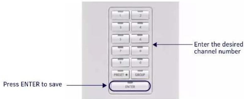
FIG. 66 Direct Selection of a Cable or Satellite Channel
NOTE: This information also applies to selecting a Digital Cable Music (DCM) Channel.
To change the Cable or Satellite (or Digital Cable Music) channel:
- Key in the Channel number.
- Press ENTER to complete.
NOTE: Strings of 2 to 4 numbers are recognized.
Examples:
• 202 + ENTER = Channel 202 CNN DTV
• 501 + ENTER = Channel 501 HBO DTV
Working with Presets
The DAS-MET-NUM can be used to store 10 presets for each source. Any Source that utilizes Direct Access can have presets programmed (including Matrix on-board AM/FM Tuners, External Tuners, Satellite Receivers, CD Players/Changers, DVD Players/Changers, Audio Servers and Satellite Radio).
NOTE: Presets are Source-specific but not Room-specific.
Creating a Preset
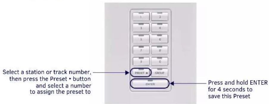
FIG. 67 Creating A Preset
NOTE: Each Source can have up to ten Presets assigned to it.
- Select a Source (CD or Tuner).
- Select the desired entry (Station or Track number).
- Press ENTER
- Press the PRESET • button.
- Enter a number for this Preset (1-10).
- Press and hold ENTER for four seconds to complete.
Example:
To set station "104.5" as "Preset 3":
a. Select a Tuner as the Source.
b. Key in "104.5" (to tune to the desired station).
c. Press ENTER.
d. Press PRESET •
e. Press 3.
f. Press and hold ENTER for four seconds.
Recalling a Preset
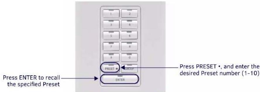
FIG. 68 Recalling A Preset
- Select a Source.
-
Press PRESET • and enter the desired Preset number (1-10).
-
Press ENTER to recall the specified Preset.
Examples:
- PRESET • + 5 + ENTER = Recalls Preset #5
- PRESET • + 1 + ENTER = Recalls Preset #1
- PRESET • + 4 + ENTER = Recalls Preset #4
Clearing All Presets
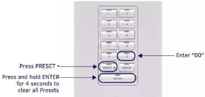
FIG. 69 Clearing All Presets
- Select a Source.
- Press PRESET •
- Enter "00".
- Press and hold ENTER for four seconds.
Example:
Press PRESET • + 00 + press & hold ENTER = All presets will be cleared.
Working with Favorites
One Favorite can be programmed via the numeric keypad for each source in each zone. Favorites might include your favorite station, channel, or CD.
If a Favorite is set for a specific source in a specific zone, when that source is turned on (after System has been Off), the favorite will begin playing in that zone.
NOTE: Favorites can only be set for Sources that utilize Direct Access functionality.
Creating a Favorite for a Specific Source
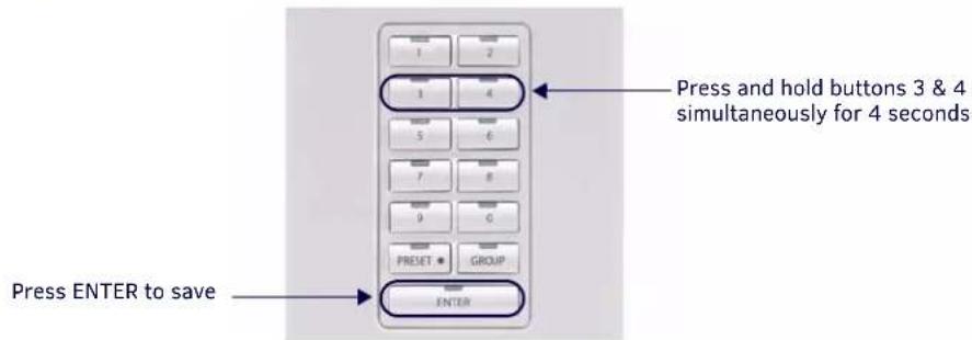
FIG. 70 Creating a Favorite for a Specific Source
- Select a Source (CD or Tuner).
- Tune or select the desired entry as the favorite for the selected Source.
- Press and hold buttons 3 and 4 simultaneously for four seconds to set the selected Favorite for this Source (LED's will turn On).
- Press ENTER to complete (LED's will turn Off).
Examples:
- Tuner - 104.5 ENTER + 3 and 4 + ENTER = 104.5FM is saved as the Favorite.
- CD - 2.4 ENTER + 3 and 4 + ENTER = Disk 2/Track 4 is saved as the Favorite.
Clearing Favorites for All Sources in a Specific Zone
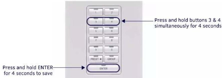
FIG. 71 Clearing Favorites For All Sources in a Specific Zone
- Select a Source (CD or Tuner).
- Simultaneously press and hold buttons 3 and 4 to enter Favorites mode for this Source (LED's will turn On).
- Key in "00".
- Press and hold ENTER to complete.
Working with Zone Grouping
In Group Mode, zones can be "grouped" together and controlled as a single zone. This feature is specifically designed to accommodate a situation where it is desirable to link a combination of rooms (zones) to a common source. For example when hosting a party and you wish to have the common areas all linked to the same audio source. When initially creating a zone group, all members of the group will have the volume set to the same level. The volume can then be adjusted on an individual zone basis, by using the Navigation Wheel (on the DAS-MET-6SRC keypad) in each zone. Group Volume may be adjusted at any time.
• To enter Group Mode, press the Group button (see FIG. 72).
- Group Mode is indicated by all Source LED's turned On.
NOTE: Group Mode can also be accessed by pressing and holding buttons 1 and 2 for four seconds (as is the case with earlier versions of Matrix keypads).
Adding a Zone to a Group
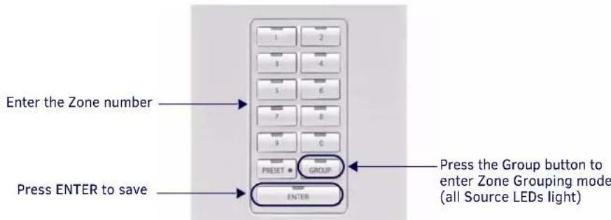
FIG. 72 Adding a Zone to a Group
- Press the Group button to enter Group Mode (all Source LED's turn On).
- Enter the Zone number to add to the group.
- Press ENTER to complete (Source LED's turn Off).
Example (from Keypad in Zone 1): - Press Group + 2 + ENTER = Zone Grouping now includes Zone 1 & 2
- Press Group + 4 + ENTER = Zone Grouping now includes Zone 1,2 & 4
NOTE: The Zone from which zone grouping is being administered, is assumed to be the first Zone in the Group. It should, therefore, not be added to the Zone Grouping.
Grouping All Zones
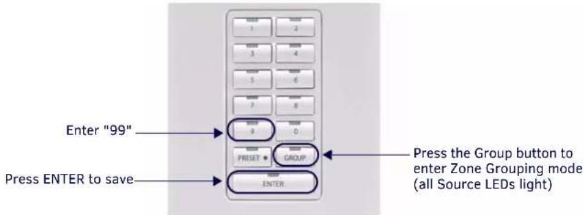
FIG. 73 Adding A Zone To Group
- Press the Group button to enter Group Mode (all Source LED's turn On).
- Enter "99".
- Press ENTER to complete.
Un-Grouping All Zones
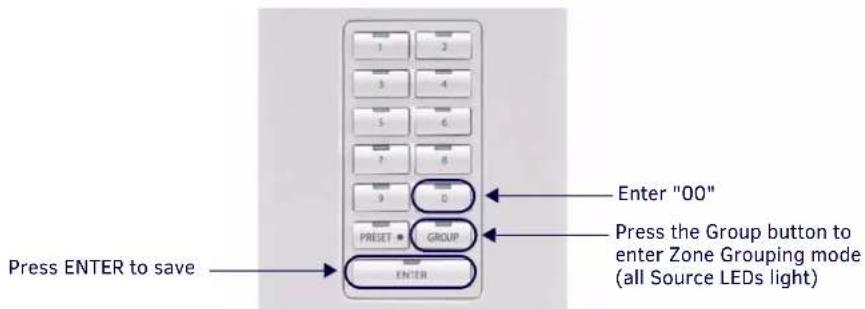
FIG. 74 Ungrouping All Zones
- Press the Group button to enter Group Mode (all Source LED's turn On).
- Enter "00".
- Press ENTER to complete.
Grouping Volume Control
When initially creating a zone grouping, all members of the group will have the volume set to the same level. The volume can then be adjusted on an individual zone basis, by using the Navigation Wheel (on the DAS-MET-6SRC keypad) in each zone. Adjusting the volume level for the entire Group can be made at any time, as described below:
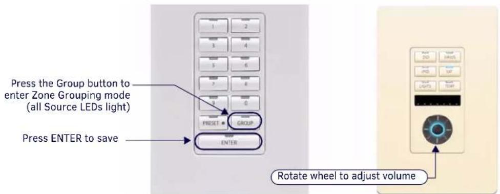
FIG. 75 Grouping Volume Control
- Press the Group button to enter Group Mode (all Source LED's turn On).
-
Adjust Volume using the Navigation Wheel (on the DAS-MET-6SRC keypad).
NOTE: All Zones will have the volume incremented by the adjustment being made. -
Press ENTER to complete.
NOTE: To bring all Zones to the same volume level (after individual Zone adjustments have been made), enter Zone Grouping mode (Buttons 1&2) and decrease the volume to 0db, then increase the volume to desired level.
Working with Alarms
To use the Alarm feature, a System Time must first be entered on the Main Controller, via the Front LCD.
To set an alarm from each Keypad, select a Source, adjust the volume, and set the alarm time (using 24HR clock, as described below).
When the alarm time is reached, the Source selected will turn On, and the volume will ramp up to the set volume and begin playing. At this point the source will behave normally.
NOTE: If a Favorite has been set, the Favorite will begin playing. Otherwise, the last station/CD will begin playing.
Setting the System Clock on the Tango Audio Controller
From the LCD on the front panel of the Tango Audio Controller:
- Select CLOCK
- Select Set Time to display the following screen (FIG. 76):
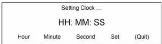
FIG. 76 Setting the System Clock on the Tango Audio Controller
- Press Hour to increment the HH (hours) from 1 through 24.
- Press Minute to increment the MM (minutes) from 01 through 60.
- Press Second to increment the SS (seconds) from 01 through 60.
- Press Set to set the clock to the time displayed.
Refer to the Tango Audio Controller Operation/Reference Guide for details.
Setting an Alarm in a Zone
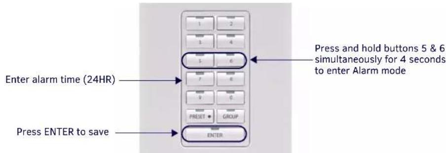
FIG. 77 Setting Alarm In a Zone
- Select Source and adjust the Volume to desired level.
- Press and hold buttons 5 and 6 simultaneously for four seconds (Source LED's turn ON).
- Enter the 24HR Time for alarm (use PRESET • to separate Hours and Minutes).
- Press ENTER to complete (source LED's turn OFF).
Example:
- Press 5 and 6 + 6 • 30 + ENTER = alarm set for 6:30 AM
- Press 5 and 6 + 18 • 30 + ENTER = alarm set for 6:30 PM
Clearing the Alarm for a Specific Zone
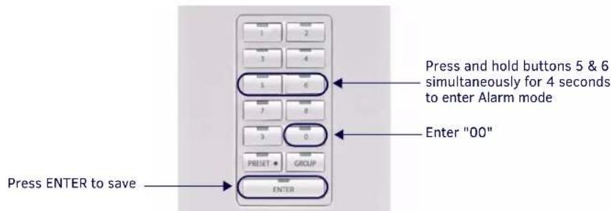
FIG. 78 Clearing the Alarm For a Specific Zone
- Press and hold buttons 5 and 6 simultaneously for four seconds (Source LED's turn ON).
- Enter "00".
- Press ENTER to complete (source LED's turn OFF).
Clearing All Alarms for All Zones
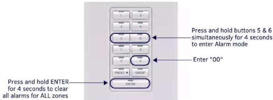
FIG. 79 Clearing All Alarms For All Zones
- Press and hold buttons 5 and 6 simultaneously for four seconds.
- Key in "00".
- Press and hold ENTER for four seconds to complete.
Keypad Lockout
Keypad Lockout functionality allows the user to lock any keypad from any other keypad in the system.
For example, if the user wants to lock the keypad in their rooms, the user can access the lockout feature from any keypad in the house. Once the keypads are locked the children can no longer control the system from the keypad in their rooms.
If the user wants to lockout a keypad's ability to control the system, it can be setup from any keypad in any zone that has a DAS-MET-NUM keypad installed.
Locking a Keypad
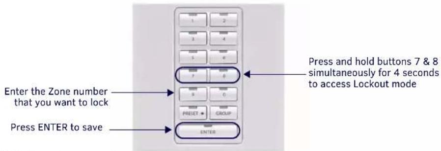
FIG. 80 Locking A Keypad
- Press and hold buttons 7 and 8 simultaneously for four seconds (Source LED's turn On).
- Enter the Zone number to Lock.
- Press ENTER to complete (Source LED's turn Off).
NOTE: You may not lockout the same keypad that you have accessed to setup the Keypad Lockout feature (so that the keypad that is accessing the lockout feature cannot lockout itself).
Examples:
- Press and hold 7 and 8 (for 4 seconds) + 2 + ENTER = keypad in zone #2 will be locked.
- Press and hold 7 and 8 (for 4 seconds) + 4 + ENTER = keypad in zones #2 & #4 will be locked.
Unlocking a Keypad
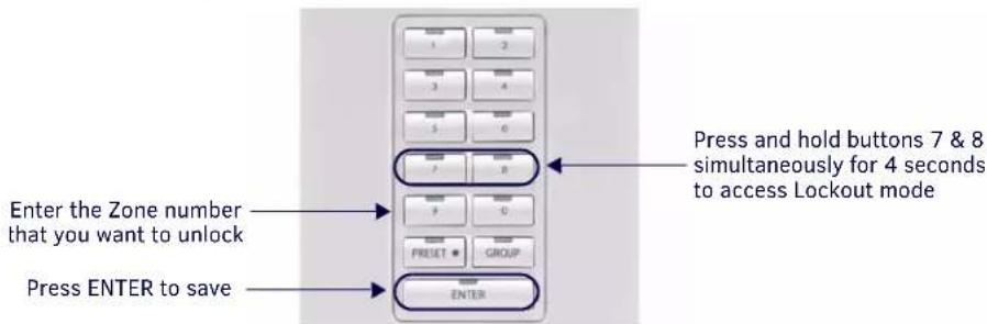
FIG. 81 Unlocking A Keypad
NOTE: Unlocking a keypad must be done at the keypad that originally locked the keypad.
-
Press and hold buttons 7 and 8 simultaneously for four seconds (Source LED's turn On).
-
Enter the Zone number to unlock.
-
Press and hold ENTER for four seconds to complete (Source LED's turn Off).
Examples:
- Press and hold 7 and 8 (for 4 seconds) + 2 + ENTER = keypad in zone #2 will be Locked.
- Press and hold 7 and 8 (for 4 seconds) + 4 + ENTER = keypad in zones #2 and #4 will be Locked.
- Press and hold 7 and 8 (for 4 seconds) + 2 + press and hold ENTER for four seconds =
- Keypad in zone #2 will be Unlocked.
- Keypad in zone #4 remains Locked.
Unlocking All Keypads
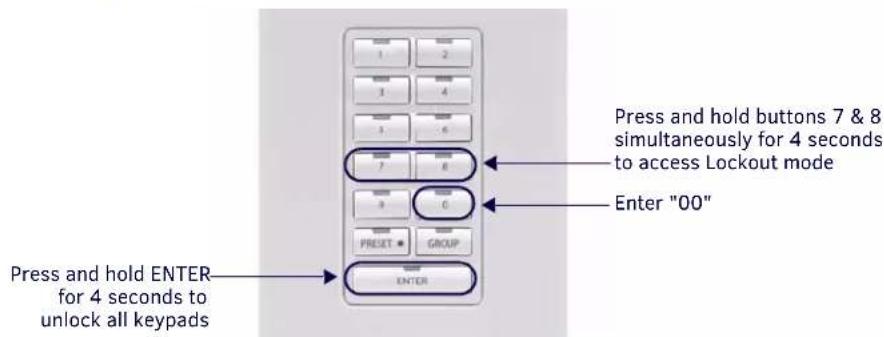
FIG. 82 Unlocking All Keypads
- Simultaneously press buttons 7 and 8 (Source LED's turn On).
- Key in "00".
- Press and hold ENTER for four seconds to complete (Source LED's turn Off).
Examples:
- Press 7 and 8 + 2 + ENTER = keypad in zone #2 will be Locked.
- Press 7 and 8 + 4 + ENTER = keypad in zones #2 & #4 will be Locked.
- Press 7 and 8 + 00 + press & hold ENTER for four seconds = Keypads in Zones #2 and #4 will both be Unlocked.
Advanced Functions - DAS-MET-6SRC
Advanced Functions - DAS-MET-6SRC
Using the NetLinx Module
Overview
The Tango system can be controlled via the Touch Pages provided with the NetLinx Module, as described in this section. Refer to the NetLinx module documentation for details on incorporating the module into your source code and loading it onto the NetLinx Master.
Main Page (Initial View)
The initial view of the touch panel pages is the Main Page, featuring the Menu Bar along the left edge, as shown in FIG. 83.
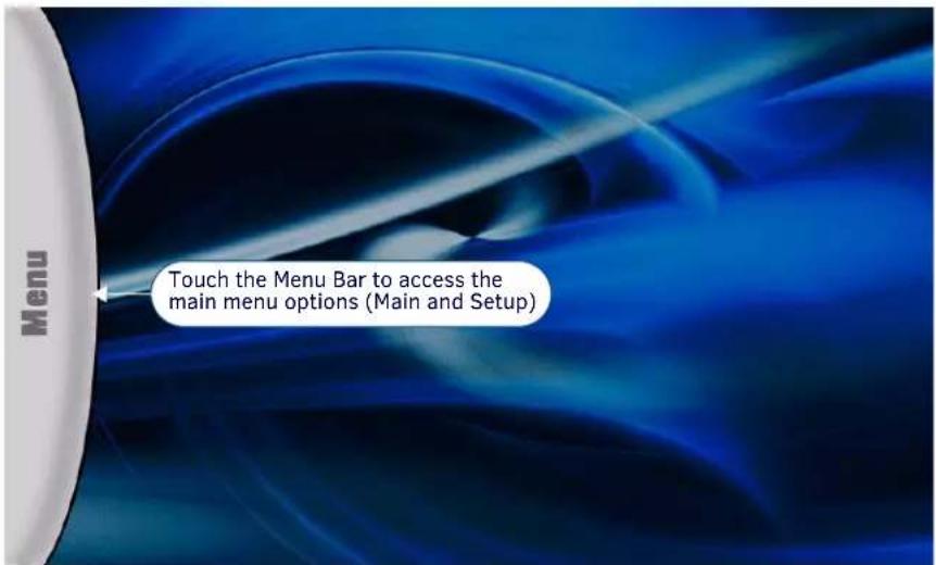
FIG. 83 Main Page (Initial View)
Press the Menu Bar to access the two primary menu options (Main and Setup), as shown in FIG. 84:
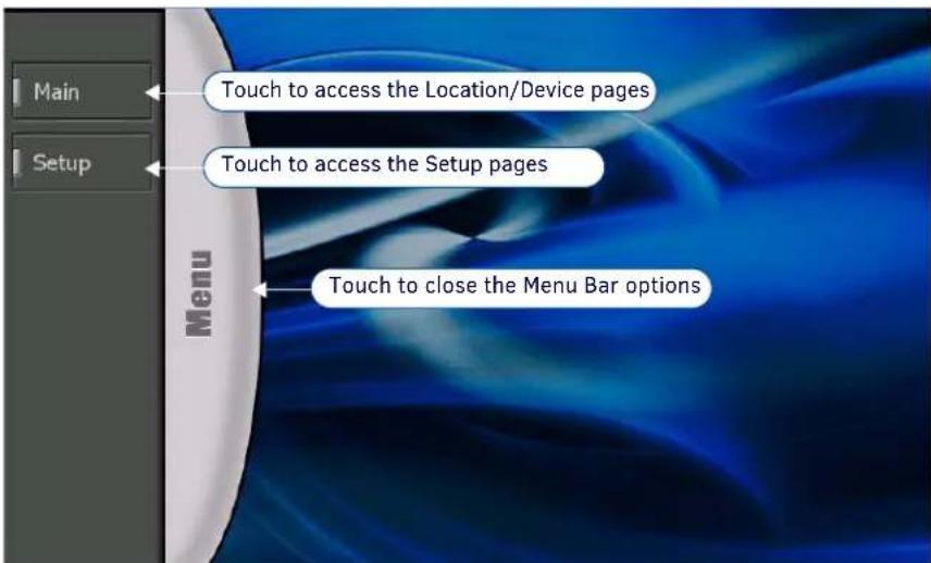
FIG. 84 Main Page - Menu Bar options
Main Pages
Press Main in the Menu Bar to access the Locations page (FIG 85). The options on this page allow you select Locations (Zones) to specify a Source Device to use with each Location, and configure audio settings for each Location.
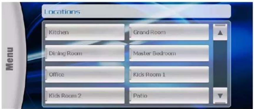
FIG. 85 Locations Page
Location/Device Pages
Press one of the Locations buttons to invoke the Location/Device page for the selected Zone. This page provides playback controls for the device currently associated with the selected Location (Zone). As an example, FIG 86 indicates that the "Dining Room" is currently using a DVD Player as it's Source Device:
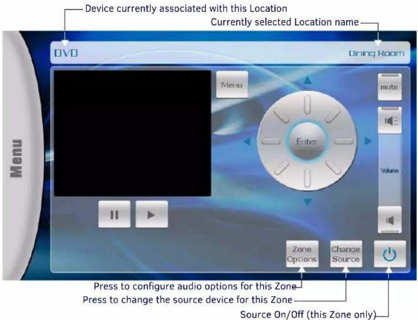
FIG. 86 Example Location/Device Page
- The currently selected Location is indicated in the upper-left corner of the page (in this case, "DVD").
- The Device currently associated with this location is indicated in the upper-right corner (in this case, "Dining Room").
NOTE: The playback controls presented on this page will vary, depending on the device type associated with the Location.
The Zone Options and Change Source buttons provide additional options:
- Press Zone Options to configure audio settings for this Location (Zone).
- Press Change Source to select a different source Device for this Location.
Zone Options
From a Location / Device page, press Zone Options to invoke the Zone Options popup shown in FIG. 87.
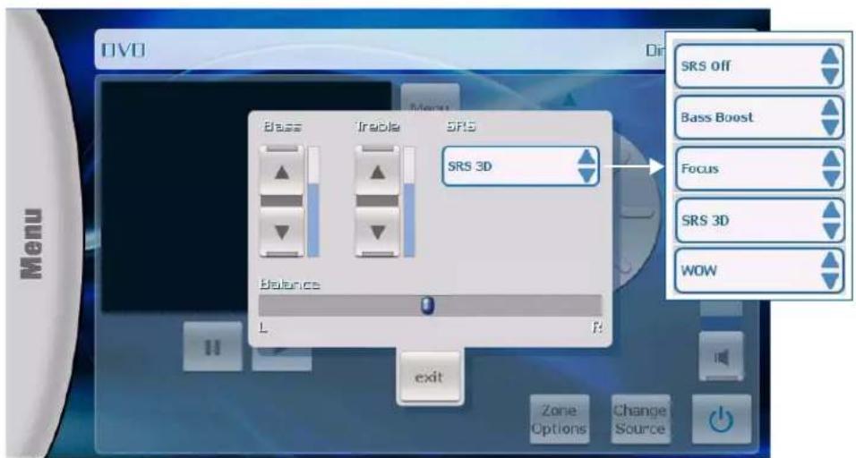
FIG. 87 Zone Options popup
- Use the Up/Down buttons to adjust Bass and Treble for this Location. The current levels are indicated in the vertical status bars adjacent to each set of Up/Down buttons (default = flat).
- Touch-and-drag the slider to adjust the Balance setting (default = centered).
- Touch the SRS menu to select an SRS mode (default = SRS Off).
- When finished, press exit to apply changes and close the Zone Options popup.
Change Source
From a Location / Device page, press Change Source to invoke the Sources page for this Location, as shown in FIG. 88.
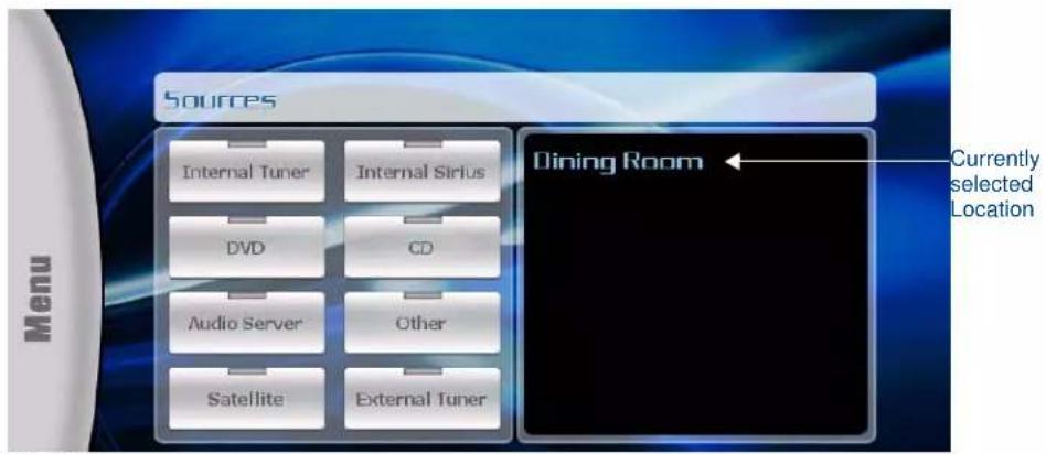
FIG. 88 Sources Page (for the "Dining Room" Location)
This page allows you to change the source device to be used for the selected Location. Note that the currently selected Location is indicated on the right side of this page.
To change sources for this Location, simply press the desired Source button. This action invokes the Device Control Page for the selected Device type. Use the options in the Device Control page to control playback.
Device Control Pages
There is separate Device Control page for each device type, with options specific to each device type, as described in the following sub-sections.
Internal Tuner
Touch Internal Tuner to invoke the Device Control page shown in FIG. 89.
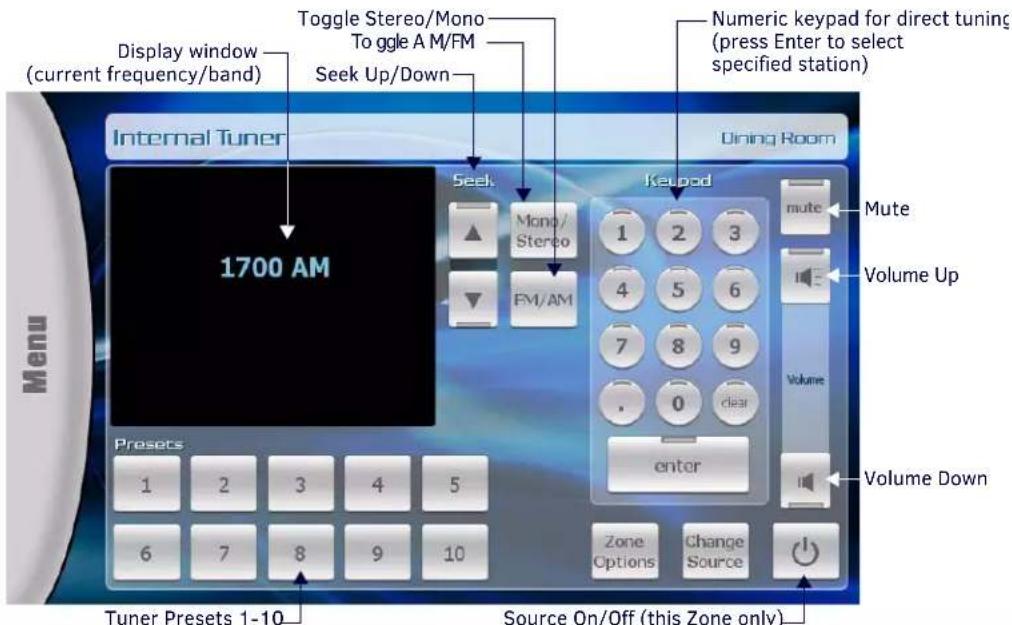
FIG. 89 Device Control page - Internal Tuner
The following table lists the option on this page.
| Device Control Page - Internal Tuner | |
| Display Window: Displays the current frequency and band (AM/FM). | |
| Seek Up/Down: Press the Up and Down arrow buttons to seek up/down on the selected band. | |
| Mono/Stereo: Press to toggle mono/stereo (default = Stereo). | |
| FM/AM: Press to toggle band (FM/AM) | |
| Keypad: Use the keypad button for direct tuning. Press enter to tune to the specified frequency. Note that the tuner automatically detects the band (AM/FM) based on the number entered. | |
| Presets: Use the Presets buttons to recall up to ten station presets. | |
| Zone Options: Press to access the Zone Options popup for configuring audio settings for the selected Location (Zone).Note that the currently selected Location is indicated in the upper-right corner of the page (see the Zone Options section on page 79). | |
| Change Source: | Press to access the Sources page for this location. Note that the currently selected Source is indicated in the upper-left corner of the page (see the Change Source section on page 79). |
| Mute: Press to mute the audio. | |
| Volume Up/Down: Press the Up and Down arrow buttons to adjust the volume up/down. | |
| Power On/Off: | Press to toggle the Source device Off/On, in this Zone only. The source device will continue playback in other Zones. |
Internal Sirius
Touch Internal Sirius to invoke the Device Control page shown in FIG. 90.
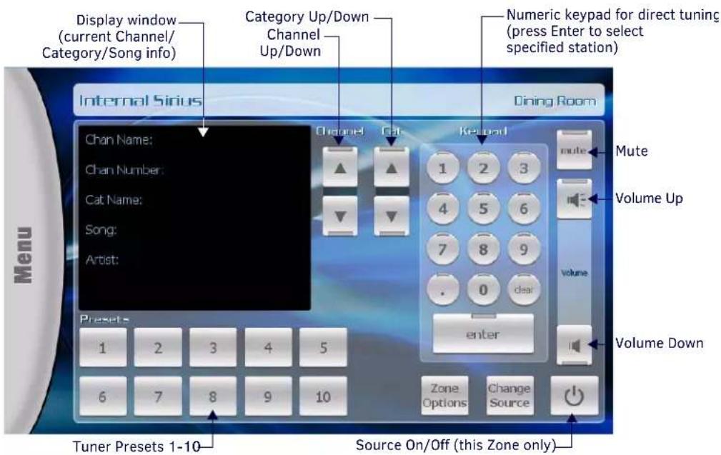
FIG. 90 Device Control page - Internal Sirius
The following table lists the option on this page.
| Device Control Page - Internal Sirius | |
| Display Window: Displays the current Channel, Category and Song Info (as provided by Sirius). | |
| Channel Up/Down: Press the Up | and Down arrow buttons to browse up/down in the selected Category. |
| Cat: Press the Up and Down arrow | w buttons to browse up/down through the Categories list. |
| Keypad: Use the keypad button for direct tuning. Press enter to tune to the specified channel. | |
| Presets: Use the Presets buttons to recall up to ten station presets. | |
| Zone Options: Press to access the Zone Options popup for configuring audio settings for the selected Location (Zone).Note that the currently selected Location is indicated in the upper-right corner of the page (see the Zone Options section on page 79). | |
| Change Source: | Press to access the Sources page for this location. Note that the currently selected Source is Indicated in the upper-left corner of the page (see the Change Source section on page 79). |
| Mute: Press to mute the audio. | |
| Volume Up/Down: Press the Up and Down arrow buttons to adjust the volume up/down. | |
| Power On/Off: | Press to toggle the Source device Off/On, in this Zone only. The source device will continue playback in other Zones. |
DVD
Touch DVD to invoke the Device Control page shown in FIG. 91.
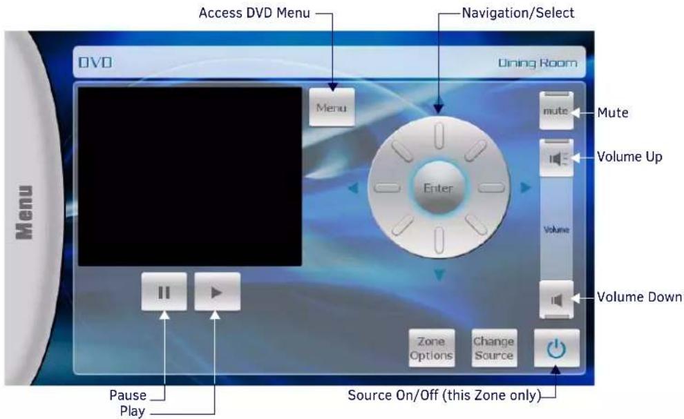
FIG. 91 Device Control page - DVD
The following table lists the option on this page.
| Device Control Page - DVD | |
| Play/Pause: Press to control DVD playback. | |
| Menu: Press to access the DVD's menu screen. | |
| Navigation/Select: | Use the directional buttons (Up, Down, Left and Right) to navigate DVD menus, and press Enter to select. |
| Zone Options: | Press to access the Zone Options popup for configuring audio settings for the selected Location (Zone). Note that the currently selected Location is indicated in the upper-right corner of the page (see the Zone Options section on page 79). |
| Change Source: | Press to access the Sources page for this location. Note that the currently selected Source is indicated in the upper-left corner of the page (see the Change Source section on page 79). |
| Mute: Press to mute the audio. | |
| Volume Up/Down: Press the Up and Down arrow buttons to adjust the volume up/down. | |
| Power On/Off: | Press to toggle the Source device Off/On, in this Zone only. The source device will continue playback in other Zones. |
CD
Touch CD to invoke the Device Control page shown in FIG. 92.
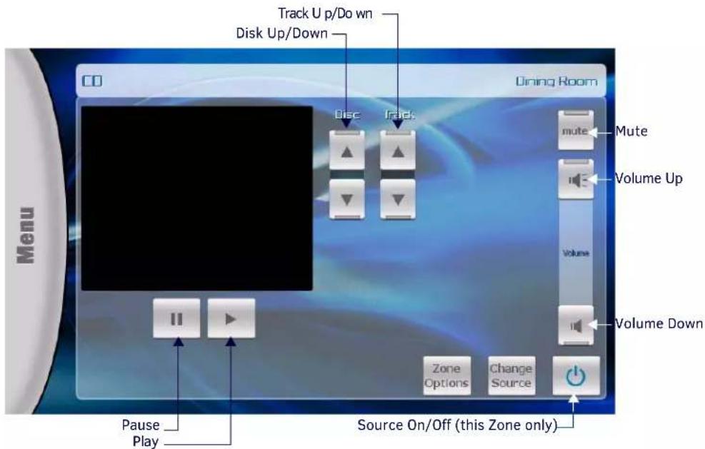
FIG. 92 Device Control page - CD
The following table lists the option on this page.
| Device Control Page - CD | |
| Play/Pause: Press to control CD | playback. |
| Disk: Press the Up button to select | ct the next CD, press the Down button to select the previous CD. |
| Track: Press the Up button to select | tect the next track, press the Down button to select the previous track. |
| Zone Options: Press to access th | e Zone Options popup for configuring audio settings for the selected Location (Zone).Note that the currently selected Location is indicated in the upper-right corner of the page (see the Zone Options section on page 79). |
| Change Source: | Press to access the Sources page for this location. Note that the currently selected Source is Indicated in the upper-left corner of the page (see the Change Source section on page 79). |
| Mute: Press to mute the audio. | |
| Volume Up/Down: Press the Up and Down arrow buttons to adjust the volume up/down. | |
| Power On/Off: | Press to toggle the Source device Off/On, in this Zone only. The source device will continue playback in other Zones. |
Audio Server
Touch Audio Server to invoke the Device Control page shown in FIG. 93.
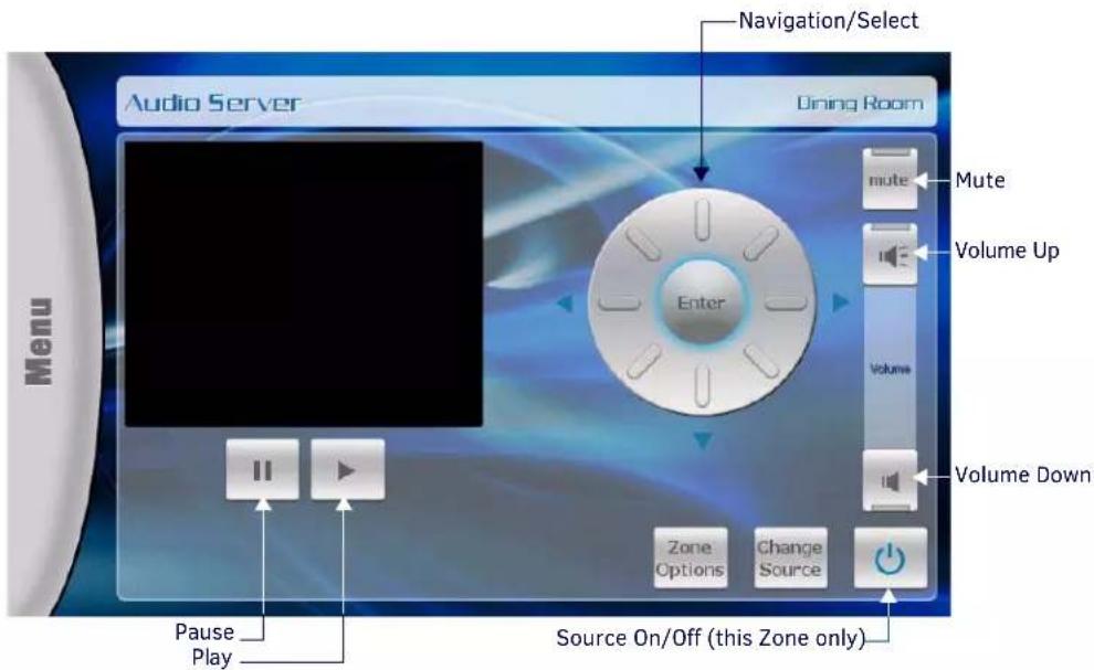
FIG. 93 Device Control page - Audio Server
The following table lists the option on this page.
| Device Control Page - Audio Server | |
| Play/Pause: Press to control CD playback. | |
| Navigation/Select: | Use the directional buttons (Up, Down, Left and Right) to navigate DVD menus, and press Enter to select. |
| Zone Options: | Press to access the Zone Options popup for configuring audio settings for the selected Location (Zone). Note that the currently selected Location is indicated in the upper-right corner of the page (see the Zone Options section on page 79). |
| Change Source: | Press to access the Sources page for this location. Note that the currently selected Source is indicated in the upper-left corner of the page (see the Change Source section on page 79). |
| Mute: Press to mute the audio. | |
| Volume Up/Down: Press the Up and Down arrow buttons to adjust the volume up/down. | |
| Power On/Off: | Press to toggle the Source device Off/On, in this Zone only. The source device will continue playback in other Zones. |
Satellite
Touch Satellite to invoke the Device Control page shown in FIG. 94.
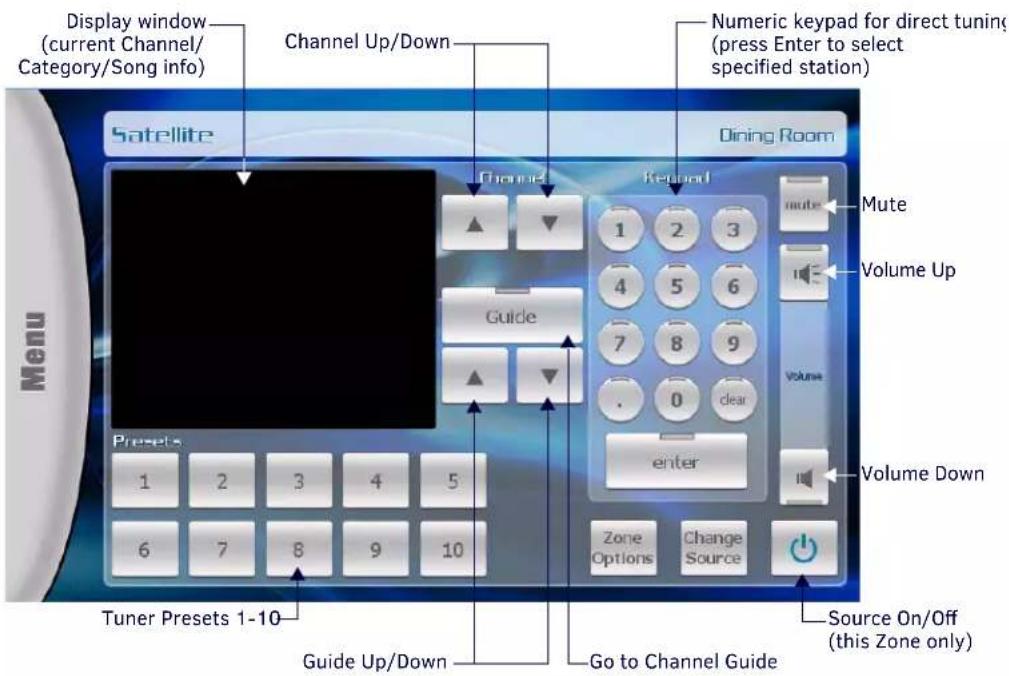
FIG. 94 Device Control page - Satellite
The following table lists the option on this page.
| Device Control Page - Satellite | |
| Display Window: Displays the current Channel, Category and Song info. | |
| Channel Up/Down: Press the Up and Down arrow buttons to browse up/down in the selected Category. | |
| Guide Up/Down: Press the Up and Down arrow buttons to browse up/down through the Guide. | |
| Keypad: Use the keypad button for direct tuning. Press enter to tune to the specified channel. | |
| Presets: Use the Presets buttons to recall up to ten station presets. | |
| Zone Options: | Press to access the Zone Options popup for configuring audio settings for the selected Location (Zone). Note that the currently selected Location is indicated in the upper-right corner of the page (see the Zone Options section on page 79). |
| Change Source: | Press to access the Sources page for this location. Note that the currently selected Source is indicated in the upper-left corner of the page (see the Change Source section on page 79). |
| Mute: Press to mute the audio. | |
| Volume Up/Down: Press the Up and Down arrow buttons to adjust the volume up/down. | |
| Power On/Off: | Press to toggle the Source device Off/On, in this Zone only. The source device will continue playback in other Zones. |
External Tuner
Touch External Tuner to invoke the Device Control page shown in FIG. 95.
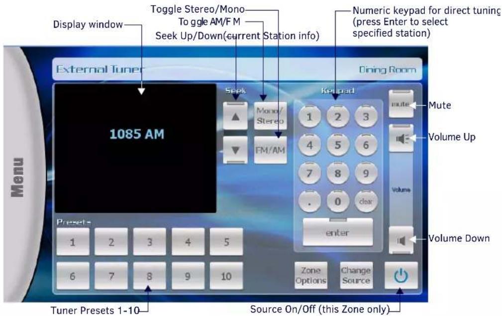
FIG. 95 Device Control page - External Tuner
The following table lists the option on this page.
| Device Control Page - External Tuner | |
| Display Window: Displays the current Channel, Category and Song info. | |
| Seek Up/Down: Press the Up and Down arrow buttons to seek up/down on the selected band. | |
| Mono/Stereo: Press to toggle mono/stereo (default = Stereo). | |
| FM/AM: Press to toggle band (FM/AM) | |
| Keypad: Use the keypad button for direct tuning. Press enter to tune to the specified frequency. Note that the tuner automatically detects the band (AM/FM) based on the number entered. | |
| Presets: Use the Presets buttons to recall up to ten station presets. | |
| Zone Options: | Press to access the Zone Options popup for configuring audio settings for the selected Location (Zone). Note that the currently selected Location is indicated in the upper-right corner of the page (see the Zone Options section on page 79). |
| Change Source: | Press to access the Sources page for this location. Note that the currently selected Source is indicated in the upper-left corner of the page (see the Change Source section on page 79). |
| Mute: Press to mute the audio. | |
| Volume Up/Down: Press the Up and Down arrow buttons to adjust the volume up/down. | |
| Power On/Off: | Press to toggle the Source device Off/On, In this Zone only. The source device will continue playback in other Zones. |
Other
Touch Other to invoke the Device Control page shown in FIG. 95.
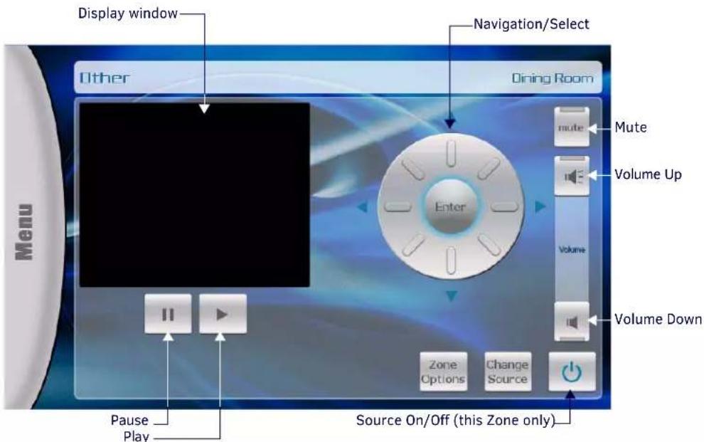
FIG. 96 Device Control page - Other
The following table lists the option on this page.
| Device Control Page - Other | |
| Display Window: Displays information on the current selection (display depends on the device type). | |
| Play/Pause: Press to control playback. | |
| Navigation/Select: | Use the directional buttons (Up, Down, Left and Right) to navigate device menus, and press Enter to select. |
| Zone Options: Press to access the Zone Options popup for configuring audio settings for the selected Location (Zone).Note that the currently selected Location is indicated in the upper-right corner of the page (see the Zone Options section on page 79). | |
| Change Source: | Press to access the Sources page for this location. Note that the currently selected Source is indicated in the upper-left corner of the page (see the Change Source section on page 79). |
| Mute: Press to mute the audio. | |
| Volume Up/Down: Press the Up and Down arrow buttons to adjust the volume up/down. | |
| Power On/Off: | Press to toggle the Source device Off/On, in this Zone only. The source device will continue playback in other Zones. |
Setup Pages
Press Setup in the Menu Bar to access the main Setup page. The options on this page allow you to access Zones and Alarms. The initial view of the Setup pages is the Zones page (FIG. 97)
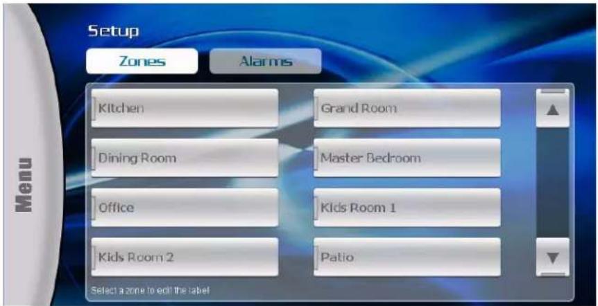
FIG. 97 Setup page (Initial view - Zones)
Setup - Zones
Touch any of the Zones buttons to edit the selected Zone's label, via the on-screen keyboard shown in FIG. 98.
![Dining Room_ Back Clear Delete End 1 2 3 4 5 6 7 8 9 0 - = Cops q w e r t y u i o p [ ] \ Shift a s d f g h j k l ; ' Enter More z x c v b n m , . / Shift Space Abort Done](/content/2026/05/959638/images/27d4ade7b7f4d243b25fc51f8cfef01a5bf897566a62027c30b355b8e9b0d923.jpg)
FIG. 98 On-Screen Keyboard (editing a Zone label)
- Press Enter to create a carriage return
- Press Done to save your changes
- Press Abort to close the keyboard, without saving changes.
Setup - Alarms
Press Alarm on the main Setup page to access the Alarms page (FIG. 99). Use the options in this page to set alarms for one or more selected Zones. An "Alarm" can be programmed to play a specific source in any specified Zone.
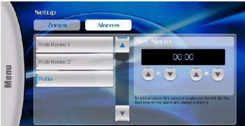
FIG. 99 Setup - Alarms page
Adding an Alarm
-
Touch one of the location (Zone) buttons to select the Zone for which you want to set an alarm.
-
Set the start time for the alarm using the H (hour) and M (minute) up/down arrows. Note that the alarm clock uses a 24-hour clock time. Refer to the following table to quickly convert regular time to 24-hour clock time standards:
| Regular Time 24-hour Clock(hour value) | Regular Time 24-hour Clock(hour value) | ||
| Midnight | 00 | Noon | |
| 1:00 a.m. 01 1:00 p.m. 13 | |||
| 2:00 a.m. 02 2:00 p.m. 14 | |||
| 3:00 a.m. 03 3:00 p.m. 15 | |||
| 4:00 a.m. 04 4:00 p.m. 16 | |||
| 5:00 a.m. 05 5:00 p.m. 17 | |||
| 6:00 a.m. 06 6:00 p.m. 18 | |||
| 7:00 a.m. 07 7:00 p.m. 19 | |||
| 8:00 a.m. 08 8:00 p.m. 20 | |||
| 9:00 a.m. 09 9:00 p.m. 21 | |||
| 10:00 a.m. 10 | 10:00 p.m. 22 | ||
| 11:00 a.m. 11 | 11:00 p.m. 23 | ||
12
- Regular and 24-hour clock time use the same number of minutes per hour and they use minutes in exactly the same way. There is no need to convert minutes when going back and forth between the two time systems.
-
The alarm clock treats midnight as the start of a new day and express it as "0000".
-
Once the time has been set, the "choose source" option is enabled (FIG. 100).
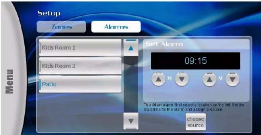
FIG. 100 Setup - Alarms page with Zone and Time selected
- Touch "choose source" to specify the source device to be used as the alarm (FIG. 101).
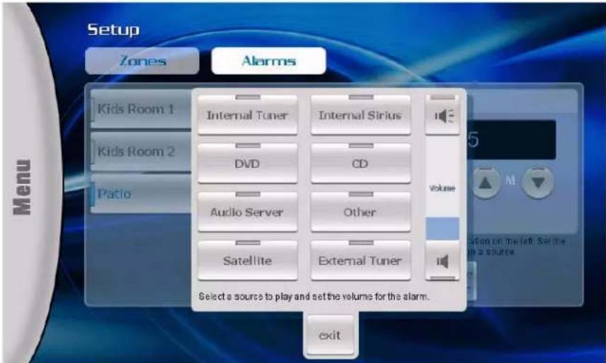
FIG. 101 Alarms page - select a Source
NOTE: The exit button allows you to close the Sources window without selecting an Alarm Source. Once a Source is selected, the Sources windows closes automatically.
- Touch the Volume Up and Down buttons on the Volume bar to set the alarm volume for the selected Source device.
- Touch "save alarm" to save your changes and return to the Alarms page.
Removing an Alarm
Once an alarm has been set for this Zone, the "Remove Alarm" option is enabled (FIG. 102).
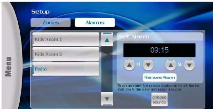
FIG. 102 Alarms page - Remove Alarm
Touch Remove Alarm to remove the alarm for the selected Zone.
SWT Troubleshooting
Overview
This section provides troubleshooting for the SWT Metreau keypads (DAS-MET-6SRC and DAS-MET-NUM).
Symptom Possible Causes Section
Everything is dead Power Power
All keypads are dead Power-cabling between MRC and keypad incorrect. Power
| (No lights) | Keypad connections reversed. | Keypad cabling |
| Some keypads ok, some dead. | Cabling between MRC & keypad shorted. Keypad connections reversed. Defective keypad. Defective cable. | Keypad Cabling. Restart system. |
| Sources don't work manually or automatically | Power Power | |
| Sources and keypads work but no sound in zone. | Speakers not connected. Problem between keypad and speakers. Problem with speakers. Volume too low. | Keypad Cabling Source Cabling |
| Sources and keypads work but no sound in zone. | RCA cables from source inserted into the source outputs. | Source Cabling |
| Sources work manually but keypads don't control device. | Device programming incomplete. Infrared emitter lead missing. IR emitter lead connected to wrong device. | Programming. Source cabling. Restart system. |
| Sources power off when selected. | Program error in ON/ OFF function. | Programming |
| Sources don't start playing when selected. | Program error in device select function. | Programming |
Power Connections
Tracking down problems that are power related are somewhat easy because the unit either powers up or it doesn't. If it does not, there are several things to check.
- Check to make sure you are attached to a functioning live electrical circuit. If the branch circuit is dead check the breaker or there may be a light switch controlling the power to the outlet. If it's on a switched circuit try to obtain power elsewhere.
- Ensure that both ends of each power cord are firmly seated in all of the source components.
- If you're plugged into power strips, check them for operation as well. Be aware these often have mini-breakers on them and you should check to ensure that power is functioning in EACH outlet.
It is not uncommon for the inexpensive power strips to fail at one plug-in but not the others. - There is a power switch located at the rear of the Controller, check to see that it is in the ON or (1) position.
- There is a fuse beside the power switch at the back of the Controller. Remove the fuse and inspect it to see that it is intact. If you have an ohm meter, test for continuity across the fuse (sometimes they look good, but they're really broken near one of the ends). If you are using a power bar they often have mini-breakers on them, and you should check to ensure that all is well. The fuse in the rear of the Unit is a T8AL250v.
Zone Connection Problems
If there is wall power and both the source components and the Controller seem to be powering up OK, but one or more of the zones are not working, there may be a problem at the individual zone or with the cabling connecting to the zone. Begin by checking each zone keypad for functionality by pressing the desired source button. The LED should light red next to the source on the KP-4e keypads or should "wake up" with a screen menu on the touch panel keypad.
Dead Zones
There is power and the source devices and the Tango Controller seem to be powering up OK, but one or more of the zones are not working.
Check each zones keypad for functionality by pressing the desired source button. The LED should light Red next to the source.
LED Does Not light
You are not getting power and command connectivity to the zone. Check other zones and select each source to determine if this is specific to the source or the room in general. If the problem is in a particular room then there may be an issue with cabling to your speakers or it may be the keypad itself. If you get similar results for a particular source in multiple zones then there may be an issue with the source equipment and you should check to see that the selected source is 'playing'. If every other zone is ok, check to make sure cables to the speakers are secure and that you have tried to increase the volume level in the zone.
Possible Causes:
• Zone connectors at Tango Controller are not secure.
- Connector at Keypad to Tango Controller is not secure.
- Wiring standard not followed. Make certain the center two wires are in the same orientation at the Tango Controller and the keypad. They may have been inadvertently reversed during the installation.
- Input and output connectors on keypad are reversed.
- Keypad not recognized by system. Restart system.
Source Connections
Problems in source cabling display some of the following characteristics.
• The source cannot be heard in any zone.
- The source doesn't seem to respond to keypad commands.
Ensure that the sources LINE OUT connections are connected to the Tango Controllers LINE IN connections for the correct device. Check to see that the IR emitter lead is securely fastened to the IR receiver on the audio source and that you have the lead plugged into the appropriate IR output jack (FIG. 103).
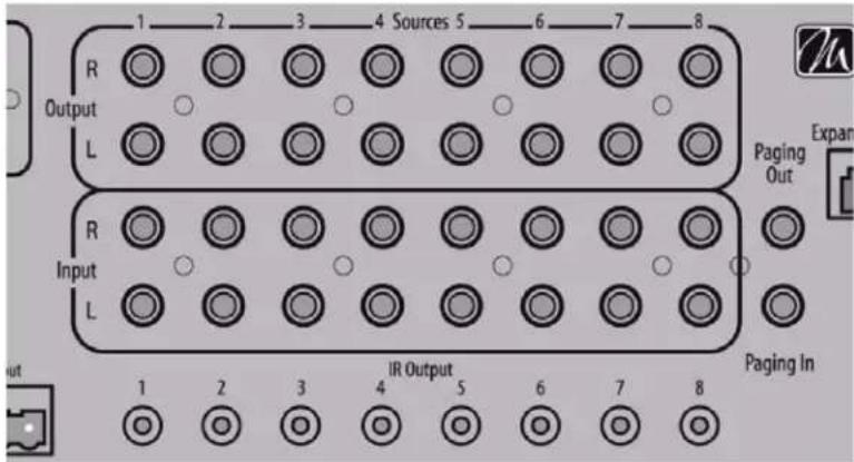
FIG. 103 Rear View – Source in/out – IR Out
When a keypad command is received and communicated to the source device, there is a LED that lights on the front of the Tango Controller indicating the processing of the command. If the LED does not light with a keypad press, then it is possible that the device has not been programmed. If the LED does light, there may be a problem with the infrared emitter lead.
TIP: For Testing, when you are having IR problems, it is helpful to carry a blinking emitter or a test emitter to ensure that the commands are being sent to the source. Techniques you can use to help isolate a sources problem include swapping the source with another on the Tango Controller to see if the problem stays with the Controller or follows the movement of the source. Also try swapping IR emitter leads. Take a look at the source to ensure that no MUTE functions have been accidentally activated.
NOTE: If you connect a keypad while the Controller is on you must restart the Controller for that keypad to become active.
No Keypad Activity
You are not getting power and command connectivity to the zone. The following are some of the possible causes:
- Verify that the AxLink address is set to 0 (zero).
• Zone connectors at the Controller are not secure. - Connector in the wall at keypad to Controller is not secure.
- Wiring and connection directions not followed. Make certain the center two wires (DATA and GROUND) are in the same orientation at the Controller and the keypad.
- Connectors on keypad from Controller and speakers are reversed.
- Keypad not recognized by system. Restart system.
Keypad Lights, No Sound
Power and command connectivity are getting to the zone. Check other zones and select each source to determine if this is specific to the source or the room in general. If the problem is in a particular room then there may be an issue with cabling to the speakers or it may be the keypad itself. If you get similar results for a particular source in multiple zones then there may be an issue with the source equipment and you should check to see that the selected source is 'playing'. If every other zone is OK, check to make sure cables to the speakers are secure and that you have tried to increase the volume level in the zone.
- IMPORTANT SAFETY INSTRUCTIONS
- COPYRIGHT NOTICE
- LIABILITY NOTICE
- AMX WARRANTY AND RETURN POLICY
- ESD WARNING
- FCC AND CANADA EMC COMPLIANCE INFORMATION:
- WEEE NOTICE:
- Table of Contents
- Metreau® Keypads 10
- Overview 10
- MET-6N and MET-6NE 6-Button Keypads with Navigation.... 12
- Navigation Wheel.... 14
- MET-7, MET-7E, and MET-7X 7-Button Keypads.... 14
- MET-13, MET-13E, and MET-13X 13-Button Keypads 17
- DAS-MET-6SRC Metreau 6-Source Audio Keypad.... 19
- DAS-MET-NUM Metreau Numeric Audio Keypad 20
- Custom Button Installation 22
- Overview 22
- Removing Buttons 22
- Button Kits.... 22
- AxLink Device Addressing 24
- Overview 24
- Device Addressing on MET-6N Keypads.... 24
- Setting the AxLink Device Address.... 24
- Mounting and Installation 26
- Mounting Dimensions.... 26
- Mounting Procedures.... 31
- Wiring and Connections 33
- Ethernet Wiring 33
- AxLink Wiring 34
- SWT Wiring 36
- Tango System Integration Drawings 38
- SWT Special Wiring Configurations.... 39
- Configuring Metreau Keypads with Ethernet 41
- Overview 41
- Updating Firmware 43
- Programming 45
- Terminal (Telnet) Commands 49
- Telnet Commands 50
- Notes on Specific Telnet Clients 55
- Enabling/Disabling Telnet on the Keypad.... 55
- Basic Keypad Functions - DAS-MET-6SRC 56
- DAS-MET-6SRC - Listening to a CD or DVD 56
- DAS-MET-6SRC - Audio Adjustment Mode 58
- DAS-MET-6SRC - Privacy Mode Off/On 60
- Working with Sources 60
- DAS-MET-6SRC - Zone Control (On/Off) 61
- Advanced Functions - DAS-MET-6SRC 66
- Using the NetLinx Module ....77
- Metreau® Keypads
- Overview
- Metreau Keypads with Ethernet
- Metreau Keypads with AxLink
- Metreau Audio Keypads (SWT Compatible)
- Overview - Speaker Wire Technology (SWT)
- Metreau Keypads Device Family
- MET-6N and MET-6NE 6-Button Keypads with Navigation
- Navigation Wheel
- Pushbuttons 7-11
- MET-7, MET-7E, and MET-7X 7-Button Keypads
- MET-7E Specifications
- MET-7X Specifications
- MET-13, MET-13E, and MET-13X 13-Button Keypads
- MET-13E Specifications
- MET-13X Specifications
- DAS-MET-6SRC Metreau 6-Source Audio Keypad
- Pushbuttons 1-6
- DAS-MET-NUM Metreau Numeric Audio Keypad
- Custom Button Installation
- Removing Buttons
- Button Kits
- Audio
- Residential
- Commercial
- Custom Keypads and Buttons
- AxLink Device Addressing
- Device Addressing on MET-6N Keypads
- Setting the AxLink Device Address
- Mounting and Installation
- Mounting Dimensions
- MET-6N, DAS-MET-6SRC
- MET-6NE
- MET-7
- MET-7E, MET-7X
- MET-13, DAS-MET-NUM
- MET-13E, MET-13X
- Mounting Procedures
- Wallbox Mounting
- Podium Mounting
- Accent Frame
- Daisy-Chaining Keypads (Ethernet Keypads only)
- Wiring and Connections
- Ethernet Wiring
- AxLink Wiring
- MET-6N, MET-7, and MET-13 Rear Panel Components
- AxLink Wiring Guidelines
- Preparing Captive Wires
- AxLink Data and Power Connections
- Using AxLink for Data with an Auxiliary Power Supply
- Orientation of AxLink Connectors
- AxLink Status LED
- SWT Wiring
- DAS-MET-6SRC and DAS-MET-7 Rear Panel Components
- Cable Type
- DAS-MET-6SRC - SWT Data and Power Connections
- DAS-MET-NUM - Connecting to the Main DAS-MET-6SRC Keypad
- Tango System Integration Drawings
- SWT Special Wiring Configurations
- Auxiliary Amplifier Configuration
- Remote Amplifier Configuration
- Two-Wire Configurations – Keypad for Control Only
- Split Zone / Analog Volume Control
- Configuring Metreau Keypads with Ethernet
- Locating the IP Address of the Keypad
- Simulating the ID Pushbutton
- Toggling Between IP Addressing Modes: DHCP and Static IP
- Assigning a Device ID to a Keypad
- Resetting the Keypad
- Restoring the Factory Image on the Keypad
- Updating Firmware
- Sending Firmware to Metreau Keypads (AxLink)
- Sending Firmware to Metreau Keypads with Ethernet
- Programming the SWT Metreau Keypads
- Programming
- Programming the Metreau Keypads
- Button Layouts
- Channels
- Port Numbers
- Programming the Navigation Wheel (MET-6N & MET-6NE)
- Navigation Wheel - Buttons 7-11
- Navigation Wheel - Buttons 12-13
- Navigation Wheel - Level Control
- Display Bargraph
- Supported SEND\_LEVELs
- Supported SEND\_COMMANDs
- LED Feedback for 2-Position Pushbuttons
- Terminal (Telnet) Commands
- Establishing a Terminal Connection via Telnet
- Telnet User Name and Password
- Additional Notes
- Setting a Telnet User Name and Password
- Telnet Commands
- Notes on Specific Telnet Clients
- Windows Client Programs
- Linux Telnet Client
- Enabling/Disabling Telnet on the Keypad
- Basic Keypad Functions - DAS-MET-6SRC
- DAS-MET-6SRC - Listening to a CD or DVD
- Selecting the Source for Playback
- Changing Tracks
- Pausing Playback
- Listening to an iPod
- Listening to the Radio
- Adjusting the Volume
- DAS-MET-6SRC - Audio Adjustment Mode
- Adjusting Bass Level For a Room/Zone
- Adjusting Treble Level For a Room/Zone
- Adjusting Balance For a Room/Zone
- Adjusting SRS Settings For a Room/Zone
- Turning SRS Off
- DAS-MET-6SRC - Privacy Mode Off/On
- Turning Off Privacy Mode
- Working with Sources
- DAS-MET-6SRC - Zone Control (On/Off)
- Turning a Single Zone On/Off
- Turning On a Source in All Zones
- Turning Off/On a Source in All Zones
- DAS-MET-6SRC - Zone Control (Dynamic Pause)
- Single Zone Listening To Source
- Multiple Zones Listening To The Same Source
- DAS-MET-6SRC - Using the Navigation Wheel
- Using the Navigation Wheel with the Internal AM/FM Tuner
- Using the Navigation Wheel with the Internal SIRIUS Tuner
- Using the Navigation Wheel with a CD Player/Changer
- Using the Navigation Wheel with a DVD Player/Changer
- Using the Navigation Wheel with a Satellite Radio/Video Box
- Using the Navigation Wheel with an Audio Server
- Using the Navigation Wheel with an External Tuner
- Using the Navigation Wheel with Other Sources
- Advanced Functions - DAS-MET-6SRC
- Direct Access
- On-Board Tuner - Direct Selection of a Radio Station
- CD Player - Direct Selection of a Disk and Track
- CD Player - Direct Selection of a Track on the Current Disk
- Cable and Satellite - Direct Selection of a Channel
- Working with Presets
- Creating a Preset
- Recalling a Preset
- Working with Favorites
- Working with Zone Grouping
- Grouping Volume Control
- Working with Alarms
- Setting the System Clock on the Tango Audio Controller
- Keypad Lockout
- Using the NetLinx Module
- Main Page (Initial View)
- Main Pages
- Location/Device Pages
- Zone Options
- Change Source
- Device Control Pages
- Internal Tuner
- Internal Sirius
- DVD
- CD
- Audio Server
- Satellite
- External Tuner
- Other
- Setup Pages
- Setup - Zones
- Setup - Alarms
- Adding an Alarm
- Removing an Alarm
- SWT Troubleshooting
- Symptom Possible Causes Section
- Power Connections
- Zone Connection Problems
- Dead Zones
- LED Does Not light
- Possible Causes:
- Source Connections
- No Keypad Activity
- Keypad Lights, No Sound
Brand : AMX
Model : MET-13
Category : Remote control