SW915 - Receiver AmpliVox - Free user manual and instructions
Find the device manual for free SW915 AmpliVox in PDF.


| Product Type | UHF Wireless Microphone Receiver |
| Model | SW915 |
| Brand | AmpliVox |
| Frequency Range | 500-900 MHz (varies by region) |
| Number of Channels | 16 selectable |
| Audio Output | Unbalanced 1/4" jack, XLR output |
| Power Supply | 12V DC / 500mA (power adapter included) |
| Dimensions (H x W x D) | 1.75 x 8.5 x 6 inches (44 x 216 x 152 mm) |
| Weight | 1.5 lbs (0.68 kg) |
| Antenna Type | Two detachable BNC antennas |
| Operating Temperature | 32°F to 104°F (0°C to 40°C) |
| Mounting | 19" rack-mountable (brackets included) |
| Controls | Power switch, Volume knob, Channel up/down buttons |
| Indicators | Power LED, Signal LED, AF peak LED |
| Cleaning Instructions | Wipe with dry cloth; avoid liquid cleaners |
| Safety Precautions | Use only supplied adapter; avoid exposure to rain or moisture |
| Spare Parts Availability | Contact AmpliVox for replacement antennas, power adapter |
| Repair Service | Refer to authorized service centers; do not open unit |
Frequently Asked Questions - SW915 AmpliVox
User questions about SW915 AmpliVox
0 question about this device. Answer the ones you know or ask your own.
Ask a new question about this device
Download the instructions for your Receiver in PDF format for free! Find your manual SW915 - AmpliVox and take your electronic device back in hand. On this page are published all the documents necessary for the use of your device. SW915 by AmpliVox.
USER MANUAL SW915 AmpliVox
natural_image
Blue square logo with white stylized 'A' letters (no text or symbols)DIGITAL AUDIO TRAVEL PARTNER
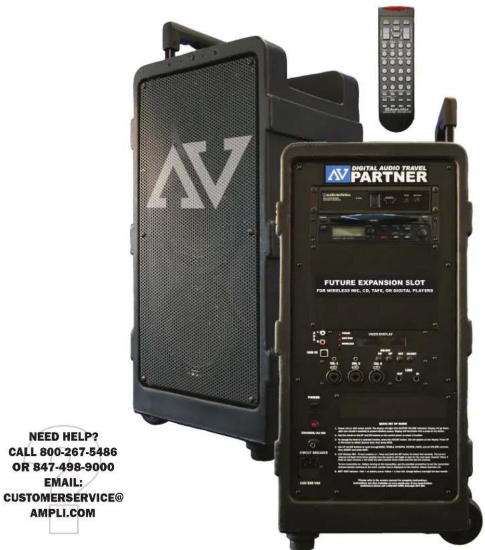
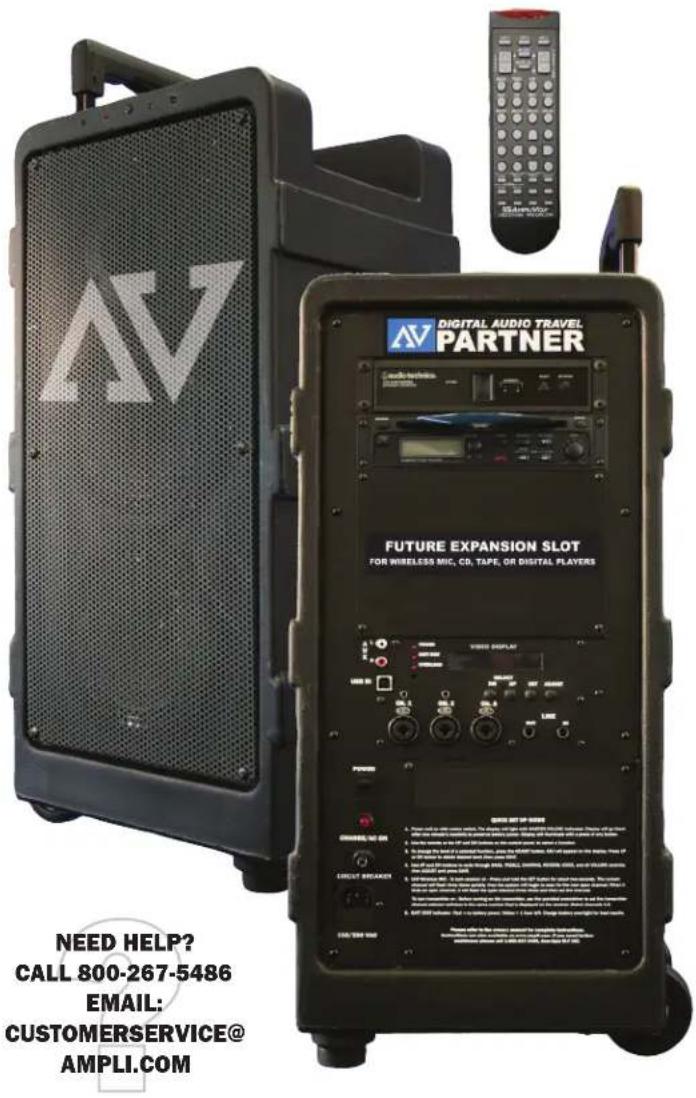
Thank you for choosing the SW915 Digital Audio Travel
Partner from AmpliVox Portable Sound Systems. We are excited in introducing a "leap forward" in portable sound systems with the incorporation of a fully digital amplifier system along with an industry leading remote control operation. Our system combines flexibility with functionality. Please refer to this user guide as you enjoy the unique capabilities of another quality product from AmpliVox Portable Sound Systems. As always, you can reach us at 800-267-5486, Monday - Friday 8am - 6pm CST.
AMPLIVOX PORTABLE SOUND SYSTEMS
PH. 800-267-5486 FX. 800-26705489
WWW.AMPLI.COM CUSTOMERSERVICE@AMPLI.COM

Made in USA
USER GUIDE
TABLE OF CONTENTS ...... 1
GETTING STARTED/QUICK SETUP 2
CONTROL PANEL FUNCTIONS .... 3
CONTROLS / INDICATORS......4
AUDIO FUNCTIONS & ADJUSTMENT 4
INPUTS / OUTPUTS......5
REMOTE CONTROL....6-7
WIRELESS MIC 8
CD PLAYER 9
OPTIONAL EQUIPMENT
DIGITAL RECORDER/PLAYER 10
CASSETTE RECORDER/PLAYER 10
TROUBLESHOOTING....11
- Power unit on with rocker switch. The display will light with MASTER VOLUME indicated.
Display will go black after one minute's inactivity to preserve battery power. Display will illuminate with a press of any button.
- Use the remote or the UP and DN buttons on the control panel, to select a function.
3 To change the level of a selected function, press the ADJUST button. ADJ will appear on the display. Press UP or DN button to obtain desired level, then press SAVE.
-
Use UP and DN buttons to cycle through BASS, TREBLE, DUCKING, REVERB, VOICE, and all VOLUME controls; then ADJUST and press SAVE.
-
UHF Wireless MIC - To turn receiver on - Press and hold the SET button for about two seconds. The current channel will flash three times quickly; then the system will begin to scan for the next open channel. When it finds an open channel, it will flash the open channel three times and then set the channel.
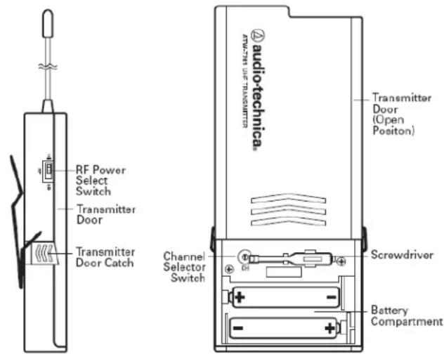
To turn transmitter on - Before turning on the transmitter, use the provided screwdriver to set the transmitter channel selector switches to the same number that is displayed on the receiver. Select channels 1-8.
- BATT STAT indicator - Red = no battery power, Yellow = 1 hour left. Charge battery overnight for best results.
If you need further assistance, please call 1-800-267-5486, 8am-6pm M-F CST.
PLEASE NOTE: THE REMOTE DOES NOT TURN THE UNIT ON OR OFF. YOU MUST DO THAT ON THE CONTROL PANEL
IMPORTANT SAFETY INSTRUCTIONS
ATTENTION: ALL SAFETY AND OPERATING INSTRUCTIONS SHOULD BE READ BEFORE OPERATING APPLIANCE. ALL OPERATING AND USE INSTRUCTIONS SHOULD BE FOLLOWED WHEN OPERATING THE APPLIANCE. HEED AND ADHERE TO ALL WARNINGS ON THE APPLIANCE AND IN THE OPERATING INSTRUCTIONS. RETAIN ALL SAFETY AND OPERATING INSTRUCTIONS FOR FUTURE REFERENCE.
WATER & MOISTURE - DO NOT USE THE APPLIANCE NEAR WATER; IE. BATHTUB, WASHBOWL, KITCHEN SINK, LAUNDRY TUB, WET BASEMENT OR SWIMMING POOL.
HEAT - SITUATE THE APPLIANCE AWAY FROM HEAT SOURCES SUCH AS RADIATORS, HEAT REGISTERS, STOVES OR OTHER APPLIANCES (INCLUDING AMPLIFIERS) THAT PRODUCE HEAT.
POWER SOURCES - CONNECT THE APPLIANCE ONLY TO A POWER SUPPLY TYPE DESCRIBED IN THE OPERATING INSTRUCTIONS OR MARKED ON THE APPLIANCE. GROUNDING OR POLARIZATION - PRECAUTIONS SHOULD BE TAKEN SO THAT THE GROUNDING OR POLARIZATION MEANS OF THE APPLIANCE ARE NOT DEFEATED. POWER CORD PROTECTION - POWER SUPPLY CORDS SHOULD BE ROUTED SO THAT THEY ARE NOT LIKELY TO BE WALKED ON OR PINCHED BY ITEMS PLACED UPON OR AGAINST THEM, PAYING PARTICULAR ATTENTION TO CORDS AT PLUGS, CONVENIENCE RECEPTACLES, AND THE POINT WHERE THEY EXIT FROM THE APPLIANCE.
OBJECT & LIQUID ENTRY - CARE SHOULD BE TAKEN SO THAT OBJECTS DO NOT FALL AND LIQUIDS ARE NOT SPILLED INTO THE ENCLOSURE THROUGH OPENINGS.
DAMAGE REQUIRING SERVICE - THE APPLIANCE SHOULD BE SERVICED BY QUALIFIED SERVICE PERSONNEL WHEN: (A) THE POWER SUPPLY CORD OR THE PLUG HAS BEEN DAMAGED (B) OBJECTS HAVE FALLEN OR LIQUID HAS BEEN SPILLED INTO THE APPLIANCE (C) THE APPLIANCE HAS BEEN EXPOSED TO RAIN (D) THE APPLIANCE DOES NOT APPEAR TO BE OPERATING NORMALLY OR EXHIBITS A MARKED CHANGE IN PERFORMANCE (E) THE APPLIANCE HAS BEEN DROPPED OR THE ENCLOSURE DAMAGED.
SERVICING - THE USER SHOULD NOT ATTEMPT TO SERVICE THE APPLIANCE BEYOND THAT DESCRIBED IN THE OPERATING INSTRUCTIONS. ALL OTHER SERVICING REFER TO A QUALIFIED SERVICE PERSONNEL.
PRODUCT PRICES, FEATURES, SPECIFICATIONS AND AVAILABILITY ARE SUBJECT TO CHANGE WITHOUT NOTICE.
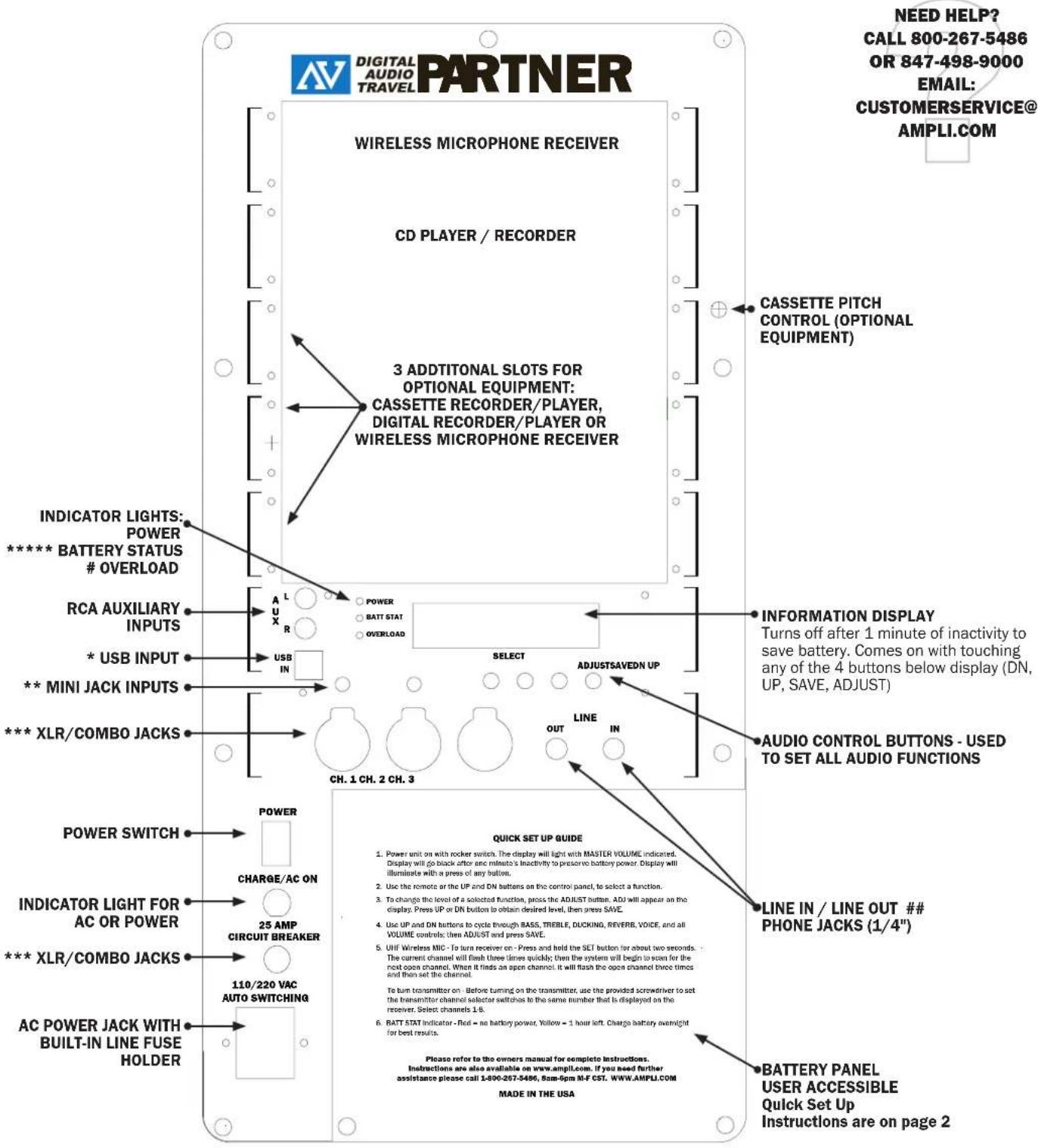
* USB In: Computer can connect here to allow audio files on computer to be played.
** Mini Jack Inputs: To connect devices as MP3 players, portable tape and CD players or any other audio device that has a 1/8-in. output.
*** XLR/Combo Jacks: To connect balanced or unbalanced microphones that have either XLR or phone plug connectors.
**** AC Power Jack: Either 110 or 220 volts can be used WITHOUT needing to move a switch; as the power supply does this action.
***** Battery Status Light: Red = No battery power, Yellow = 1 hour left of battery power. For best results - charge battery overnight.
Overload light: Lights up when volume is turned up too far and could cause audible distortion.
1/4-in. Phone Jacks: Can be used for outboard processors, musical instruments and recorders.
ON-OFF SWITCH:
When power switch is in the ON position, the BATTERY STATUS LIGHT will be illuminated. The color of the LIGHT indicates the condition of the battery.
Yellow - battery low, recharge immediately
Red - battery must be recharged before use
To charge the batteries, connect the unit to 110VAC using the supplied power cord. The red CHARGER ON LED will be illuminated indicating battery is charging. The batteries will charge when unit is operating with AC power, HOWEVER the unit will charge faster with the power switch in the "off" position.
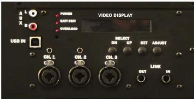
MICROPHONE VOLUME:
THE SW915 MUST BE PLUGGED IN AND CHARGING WHEN NOT IN USE There are three microphone input channels, (Channels 1, 2 & 3 on the TO MAXIMIZE BATTERY LIFE. RECHARGING THE UNIT ONLY WHEN Control Panel) and each channel has individual volume adjustment THE BATTERY STATUS LIGHT IS YELLOW OR RED WILL SHORTEN THE controls. USEFUL LIFE OF THE BATTERIES.
MASTER VOLUME:
This is the master volume control for the system.
TREBLE:
This control cuts or boosts the treble level.
BASS:
This control cuts or boosts the bass level.
VOICE/MUSIC:
Using the remote, press the V/M button to toggle between voice or music. For speech, it provides a midrange boost for better sound projection when in the VOICE position. This selection can also be performed without use of the remote. Use the up or dwn buttons just below the display on the Partner to scroll to the voice/music selection. Use the Adjust button to toggle to either Voice or Music. Then press Save to save your selection.
AUDIO FUNCTIONS AND ADJUSTMENTS
DUCKING CONTROL
The 'Ducking' feature facilitates announcements and paging by automatically reducing the volume of all the other inputs when the designated master input is used.
When Ducking is enabled, either wired microphone channel 1 or wireless microphone 1 is set as the system 'Master.' When the sound picked up by the master exceeds the 'Threshold' volume, all the other input volumes in the SW915 are reduced to the 'Attenuation' level. When the volume of the 'Master' drops below the 'Threshold' level for the time set as 'Delay', the volumes of the other inputs return to normal. There are four controls
1 DUCKING: this control activates which source of the 915 that will be used in the ducking circuit. The three settings are 'Disabled', 'Microphone 1', and 'Wireless 1'. Select either 'Microphone 1' or 'Wireless 1, to choose which of these two microphones are to be the main microphone. Select 'Disabled' to turn the Ducking Control off.
2 ATTENUATION: this determines the sound level to which the other channels will be reduced to when speaking into the main microphone. All the way down will mean there will be no effect on the other channels
3 THRESHOLD: This determines how loud the person speaking into the main microphone has to be when the Voice Ducking feature is active. This can help prevent any unwanted background noises from inadvertently activating this feature.
4 DELAY: This determines how long the Voice Ducking stays active after the last sound through the main microphone is detected - a period of silence will follow after the last sound, and the length of that period of silence will be determined by this setting.
ECHO/REVERB
This is a sound effect feature that makes the audio signal sound as though it's in a large area, such as a large cathedral or a cave, by repeating the sounds that come into the SW915 through the microphones or any of the accessories. The listener will hear the original sound, plus the repeated sounds created by this feature. There are two controls:
1 LEVEL: this control determines the loudness of the echo. In the low setting the repeated sound is perceived to be quite relative to the original sound level. As the level is increased the volume of the echo gets louder.
2 DELAY: this control determines the amount of time that elapses between the original sound and the echo. As the level is increased, the amount of delay between the original sound and the echo is increased.
TREBLE:
This control cuts or boosts the treble level.
BASS:
This control cuts or boosts the bass level.
PHANTOM POWER
The three microphone inputs on the control panel of the 915 can be configured to supply phantom power for certain types of microphones, such as condenser types, which require an extra voltage to operate:
Setup, Phantom Power: by selecting this function and using the adjust command, the user can activate the phantom power for each individual microphone channel by scrolling to the channel where the phantom power is needed, and then activating or de-activating the phantom power as needed.
MICROPHONE/INSTRUMENT INPUTS:
There are 3 types of input jacks on your DIGITAL AUDIO TRAVEL PARTNER, as follows:
2 - 1/8" phone jacks (3.5 mm)
2 - RCA jacks
3 - XLR or 14 " combination jacks (this jack will accept either type) There are two types of microphones the DIGITAL AUDIO TRAVEL PARTNER is designed for Dynamic - for standard dynamic cartridge microphones Condenser - for electret or condenser microphones, which require phantom power (supplied from the amplifier)
There are three microphone channels (Channel 1, Channel 2, and Channel 3), and each channel has individual volume controls. Each channel will accept any of the listed microphone types, but only one microphone or instrument should be plugged into each channel at a time.
Add pre-recorded music to your presentations with the internal CD or tape player. Channel 3 Volume Control adjusts the volume for these units. In addition, an external source such as a computer or MP3 player can be used by connecting to jack(s) on any available channel.
RECORD/LINE OUT:
This jack provides the output of the mixer. To record or connect to a house PA system, external equalizer, audio mixer, or transmitter of AmpliVox S1297-70 wireless powered companion speaker, connect the LINE OUT on the amplifier, to the input on an external recorder or PA system. This jack functions the same as a signal "send". (See Special Features Section)
USB INTERFACE
When a computer is connected through the USB interface, the audio portion of any multimedia programs (such as PowerPoint, Windows Media Player, etc.) used on the computer will be heard on the 915. The volume and tone controls in the computer program will determine the loudness and sound characteristics of what's heard from the computer program through the 915.
LINE INSERT
Use this jack to supply a signal directly to the power amp. This ja functions as a signal "return". Doing so will disconnect the mixer section of the DIGITAL AUDIO TRAVEL PARTNER and instead will apply the signal supplied to this jack directly to the power amp and speakers of the SW915. This input along with the record/line out can be used to electronically insert an external device such as a graphic equalizer between the mixer and the power amp to provide additional signal processing. (See Special Features Section)
Mixer stage – includes all the individual volume controls, input jacks (14"-XLR combo, 3.5mm, RCA) and mic/line & phantom power switches for the 5 input channels (2 internal wireless, 3 direct or corded) 'Record/Line Out' and 'Line Insert' stage – see below.
Output stage - includes the music/voice switch, treble, bass & master volume controls, power amps and speakers.
SPECIAL FEATURES
The DIGITAL AUDIO TRAVEL PARTNER panel has 14 " phone jacks labeled 'Record/Line Out' and 'Line Insert' respectively. 'Record/Line Out' provides a feed from the Mixer stage, but before this signal goes through the Output stage. In other words, this signal is not affected by settings on the music/voice switch, treble, bass & master volume controls. It can be used to drive an external recording device or another audio system. The advantage to this configuration (pre-EQ & master volume) is that the external system's own EQ & volume settings can be
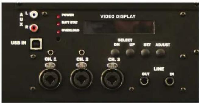
separately adjusted to suit its environment and the two systems do not interact with each other.
The 'Line Insert' jack works in two ways. When no plug is inserted it internally connects the Mixer to the Output. However, when a plug is inserted it disconnects the Mixer from the Output, replacing it with the external audio signal from the device the plug's cable is attached to. In this configuration, the DIGITAL AUDIO TRAVEL PARTNER Output stage can be used to amplify a feed from an external mixer or playback device. For instance, assume a facility's main meeting room has a built-in sound system, but the adjoining room for the overflow crowd has no system. A 'Line Out' feed from the house system could be plugged into the 'Line Insert' jack of a DIGITAL AUDIO TRAVEL PARTNER located in the overflow room. The DIGITAL AUDIO TRAVEL PARTNER's EQ & master volume can then be adjusted to suit the overflow room's conditions without any effect on the main system.
The other way this pair of jacks can be used is to insert an external device such as a graphic equalizer, echo/reverb machine or other audio processing device between the Mixer and Output stages of the DIGITAL AUDIO TRAVEL PARTNER. The 'Record/Line Out' on the '915 connects to the 'Line In' of the external device and its 'Line Out' connects to the '915 'Line Insert'. Remember from the above discussion that a plug in the 'Line Insert jack breaks the direct internal connection from the Mixer so in effect the external device is electrically inserted between the 2 stages and becomes a functional block of the DIGITAL AUDIO TRAVEL PARTNER.
FUSES
There are two circuit protection devices that are user serviceable. The 25A circuit breaker protects the power supply and battery circuits. Press to reset.
There is also a fuse in the AC jack. It is identified on the plastic with a drawing of a fuse. ***DETACH THE AC CORD FROM THE UNIT BEFORE FUSE REPLACEMENT*** This fuse protects the AC circuitry. Use a flat blade screwdriver in the slot on the top of fuse holder to slide the fuse holder out. Replace the fuse with a 10A/250V fuse if needed. If after resetting and replacing the breaker and fuse, the SW915 Digital Audio Travel Partner does not "power on", please call AmpliVox Customer Service at 800-267-5486.
WARNING! RISK OF SHOCK! DO NOT OPEN UNIT NO USER SERVICEABLE PARTS INSIDE!
There are two yellow lights located above the speakers on the 91 These lights are WIRELESS 1 & WIRELESS 2. They mean that the power is on and they are ready to use.
In models equipped with one wireless microphone receiver, the first light (from left to right) is active.
In models equipped with two wireless receivers, the first light will be the indicator for Wireless Receiver #1 (from top to bottom on the control panel) and the second light is the indicator for Wireless Receiver #2
BATTERY STATUS LED INDICATOR: LED is green when battery voltage is sufficient for operation. The LED Battery Status indicator turns red when the battery voltage is low indicating that the unit should be plugged into AC for continued operation.
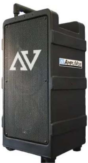
THERE ARE 4 LIGHTS ON THE S.SPEAKER SIDE OF THE DIGITAL AUDIO TRAVEL PARTNER. THEY ARE FROM LEFT TO RIGHT: WIRELESS 1 WIRELESS 2 BATTERY STATUS POWER
natural_image
Black speaker or audio amplifier device with 'AV' logo and 'AMPUVOX' label (no readable text beyond branding)REMOTE CONTROL
REMOTE CONTROL PICKUP PATTERN
The remote control for the 915 can be used to operate the controls from any direction around the 915, unless the user is standing directly in front of the speakers. Also, the remote control will operate the 915 from a distance of up to 50 feet, and be in direct line of sight for best results. 2 "AA" batteries are included. Velcro is included to attach your remote to the SW915.
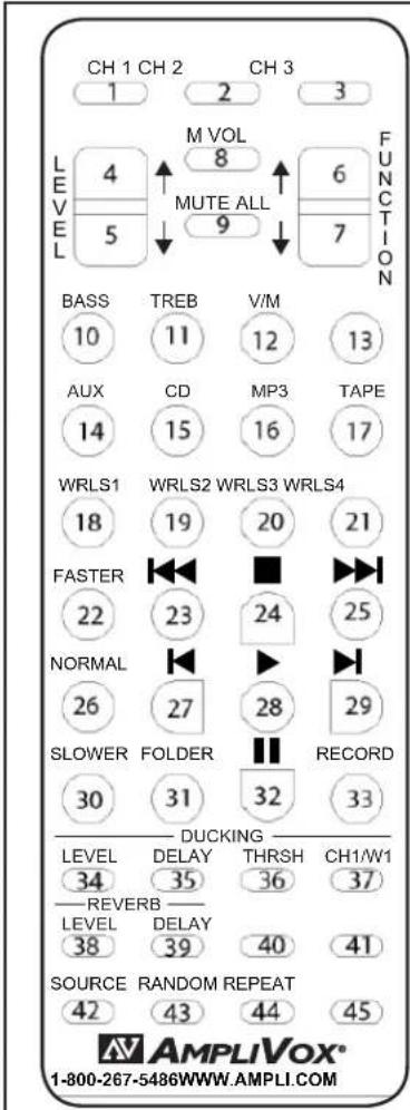
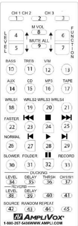
1, 2, 3: Select the numbered Channel Control Button to adjust that channel's audio. These channels refer to the Combo and 1/8 mini jacks
4 & 5: Adjusts the level of the selected function. Press 4 to raise level and 5 to lower level. Level adjustments are for the selected function such as volume
6 & 7: Function Selector- Used to scroll through functions for selection
8: Master Volume Selector- A short cut key that allows quick adjustment of Master Volume. Just press this key and then the level keys to adjust the Master Volume
9: Mute All-Press this button to mute ALL audio output (Panic button)
10: Bass Control- Press this button and bass will be displayed. Then use level buttons 4&5 to adjust
11: Treble Control- Press this button and treble will be displayed. Then use level buttons 4&5 to adjust
12: Voice/Music switch- Press this button to toggle between voice and music. In the Voice position, the vocal frequencies are enhanced to produce louder and clearer vocals. These effects are absent in the music position to allow "uncolored" music to be heard.
13: Not Used
14: Auxiliary Selection- Press this button to select the Auxiliary function controlling the red/white RCA inputs.
15: CD Selection- Press this button to select the CD player for audio adjustments and CD player controls.
CD PLAYER BUTTON
16: MP3 Selection- Press this button to select the (OPTIONAL) Digital Player/Recorder for audio adjustments.
17: Tape Selection- Press this button to select the (OPTIONAL) Cassette Player/Recorder for audio adjustments.
18-21: Wireless Selectors- Press these buttons to select a wireless receiver for audio adjustments.
22-33 AND 42-44: CD PLAYER CONTROLS
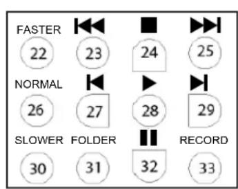
TRANSPORT CONTROLS
FASTER: Speeds up (in steps) the selection being played on the CD player.
NORMAL: Returns the playing speed to normal if the selection is being played faster or slower.
SLOWER: Slows down (in steps) the selection being played on the CD player.
: Backup the current selection to an earlier point in the recording. Press the (play) button to stop backing up and resume playing from the point the backup process was stopped.
: Go back to the beginning of the previous selection.
FOLDER: USB device and SD Card only; Changes the folder number to be played.
: Stop the selection being played. Press once to stop and keep the selection at the point where it was stopped, and when the (play) button is pressed, the selection will resume at the point where it was stopped. Press twice to completely stop the CD from playing. Pressing the (play) button will start the CD from the beginning of the first selection on the disk.
: Plays the current selection when pressed.
: Temporarily stops, or "pauses" the selection being played. Press this key again to resume playing the selection.
: Mo▶ the current selection up to a later point in the recording. Press the (play) button to stop moving forward and resume playing from the point the forwarding process was stopped.
: Go the beginning of the next selection.
RECORD: Not applicable at this time.
SOURCE: Switches the source between the CD player, USB input and SD card input.
RANDOM: Plays the selections on the CD, USB device or SD card back at random.
REPEAT: Restarts the CD, USB device or SD card from the beginning of the first selection after the last selection has been played.

SOURCE CONTROLS
Ducking/Talk Over Section
34: Ducking Level-Press this button and Ducking Level will be displayed. Then use level buttons 4&5 to adjust
35: Ducking Delay: Press this button and Delay will be displayed. Then use level buttons 4&5 to adjust the delay
36: Threshold selection- Press this button and Threshold will be displayed. Then use level buttons 4&5 to adjust
37: Ducking Channel Selector- Press this button to toggle between Wired Chanel One and Wireless Channel One
Reverb Section
38: Reverb Level- Press this button and Reverb Level will be displayed. Then use level buttons 4&5 to adjust
39: Delay Level- Press this button and Ducking Level will be displayed. Then use level buttons 4&5 to adjust
PLEASE NOTE: THE REMOTE DOES NOT TURN THE UNIT ON OR OFF. YOU MUST DO THAT ON THE CONTROL PANEL
We use only the best wireless microphones for our PA systems. Audio-Technica's 700 Series Freeway wireless delivers professional features and sound quality unheard of in its class. These easy-to-use wireless systems feature eight selectable frequency-coordinated channels, diversity operation for increased range/reliability, automatic frequency scanning, Tone Lock™ squelch and more. For multiple-mic applications, as many as eight systems may be used together.
TRANSMITTER SETUP, CONTROLS AND FUNCTIONS
BATTERY SELECTION:
Two 1.5V AA type alkaline batteries
BELT PACK Transmitter Battery Installation:
- Open the transmitter door by first pulling the catch down and then sliding the door upward.
- Observe correct polarity as marked and carefully insert two fresh 1.5V AA alkaline batteries.
- Slide the door closed making certain it clicks securely in place.
HANDHELD Wireless Microphone Battery Installation:
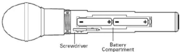
THE POWER SWITCH ON THE HANDHELD MICROPHONE IS BUILT INTO THE POWER/MUTE/BATTERY BUTTON, WHICH IS LOCATED ON THE BASE OF THE MICROPHONE.
- Unscrew the lower body cover slide it downward, and remove it to expose the battery compartment.
- Observe correct polarity as marked inside the battery compartment and carefully insert two fresh 1.5V AA alkaline batteries. Insert the first battery and slide it toward the spring contact. Then insert the second battery into the space remaining. Make certain the batteries are fully seated in the battery compartment.
- Slide the lower body compartment back on and screw the housing together. Do not over tighten.
Note: Remove batteries from the handheld transmitter starting at the bottom end, where finger indents in the battery housing are provided for easy grip.
Power /Mute Battery Indicator:
After the battery is installed, press and hold the power button unit until the battery indicator LED turns green (it will first turn red, keep holding until it turns green). If the battery indicator LED does not light up when the power button is pressed, the batteries are installed incorrectly or they are dead. The LED will flash to indicate low-battery condition. Press and hold power button to shut unit off (light shuts off).
Mute Function:
With the transmitter on, a slight touch of the Power/Mute button will toggle between muted and live operation. Red led indicates muted operation, Green LED indicated live operation.
RECEIVER CONTROLS AND FUNCTIONS
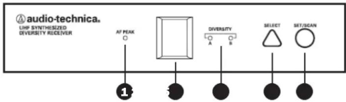
ANTENNAS: Are positioned internally at the optimal 45 degree angle for best reception.
1 - AF PEAK INDICATOR: Indicates when maximum transmitter modulation without distortion has been reached. Not affected by position of Volume control (Fig. C).
2 - LED WINDOW: LED Display indicates channel setting and scanning operation.
3 - DIVERSITY INDICATORS: Indicates which antenna (A or B) has better reception and is in operation.
4 - SELECT BUTTON (for manual channel selection): Press the Select button repeatedly until desired channel is reached. Press and hold the Set/Scan button to manually set the receiver to indicated channel. Channel number will stop flashing. (A brief touch of the Set/Scan button will revert to previously set channel). If the Set button is not pressed within 10 seconds to confirm the selection, the system will revert to its original channel.
5 - SET/SCAN BUTTON: The Set/Scan button can be used in two ways: 1) in conjunction with the Select button to permit manual selection of an operating channel in Manual Set Mode (see "Select button" description above); and 2) Automatic Scan/Set Mode, to initiate the automatic channel scan and selection, as follows: Automatic Scan/Set Mode: Press and hold the Set/Scan button for about two seconds. The current channel will flash three times quickly; then the system will begin to scan for the next open channel. When it finds an open channel, it will flash the open channel three times and then set the channel. (If an open channel is not found, the automatic scan will return to the original channel and flash 5 times.)
CAUTION! The small trimmer controls are delicate; use only the supplied screwdriver. Do not force the trimmers beyond their normal 180 degree range of motion.
Return the screwdriver to its storage clip when not in use.
To operate the CD player with the remote control, the button on the remote labeled CD (15) must be pressed first, in the same manner as when adjusting the volume for the CD player. Once the CD button is pressed, buttons 22-32 and 42-44, will continue to control their respective functions on the CD Player until one of the other input buttons is pressed.
HANDLING THE DISCS:
Always insert a CD, CD-R, CD-R/W into player with label side up! Proper handling and care of CDs should be taken to insure proper operation. Fingerprints and dust should be carefully wiped off the surface, starting from the center of the disc and moving out towards the edge. It is best to avoid touching the surface opposite the label to prevent scratching or leaving fingerprints on the surface area. Always remove disc from player before transporting unit.
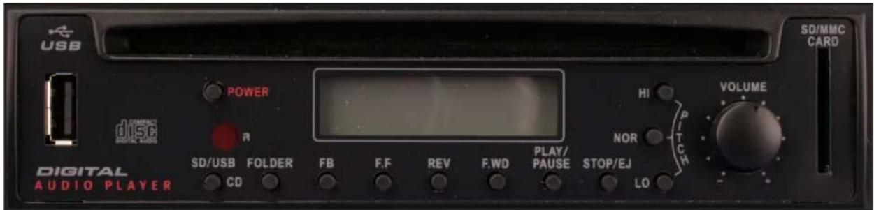
NOTE: CD will play automatically when Digital Partner is powered on if CD is left inside the CD player.
POWER:
Press POWER button to turn CD Player on.
LOADING AND UNLOADING DISCS:
To insert disc, gently insert into disc player slot until engagement mechanism pulls CD into player. Do not force CD into unit.
To remove disc press STOP/EJECT button twice and gently remove CD, place CD back into jewel case.
NORMAL DISC PLAY:
Insert CD into player and press PLAY/PAUSE button if CD hasn't already begun to play. Disc play will start at first track. Player display will indicate track number and time.
To operate the CD player with the remote control, the button on the remote labeled CD must be pressed first.
The CD player has been upgraded to add USB & SD Card playback and now functions with the 915 remote control.
Please note the following new features:
- USB 2.0 'A' input for memory devices containing compatible audio files (MP3).
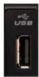
- SD Card Slot for SD cards containing compatible audio files (MP3).
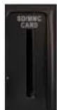

- SD/USB/CD Button on far left of button row selects between SD, USB and CD playback.
- FOLDER button selects which folder in USB or SD storage devices to play back.
• FB skips back to the previous folder or selection.
- F.F skips forward to the next folder or selection.
- REV backs up on the current folder or selection.
• F.WD moves forward on the current folder or selection.
- PLAY/PAUSE starts playback of the current folder or selection, and also stops the selection when pressed during playback. When the button is pressed again, playback resumes at the point where the selection was stopped.
- STOP/EJ stops the selection from playing. Pressing and holding the button for a couple seconds after the CD has stopped playing will eject the CD disk from the player.
- PITCH CONTROL is adjusted by three push buttons next to the volume knob:
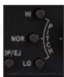
- Press and hold HI to speed up playback material over a range.
• NOR adjusts the speed back to normal speed.
- Press and hold LO to slow down playback material over a range.
• VOLUME knob increases the output level when turned clockwise, and decrease the volume when turned counter clockwise. This is in addition to the volume control function CD Volume in the preamp, and is a convenience for balancing the output with other sources.
For optimum playback leave the master volume at 1 o'clock and adjust the preamp volume for proper listening levels.
DIGITAL PLAYER / RECORDER S1960 (OPTIONAL EQUIPMENT)
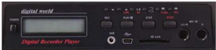
■ Built-in 128MB NAND flash memory equipped for 120 min. recording time.
■ SD card slot- supports industry standard SD cards up to 2GB, providing up to 32 hours record time per card.
■ USB port connects to PC, which sees it as an external storage device (no special driver required); or other USB - capable device for easy download or duplication.
■ Up to 99 recording tracks.
■ Play MP3 & WAV format files.
■ Digitally record in MP3 compression format, high sample rate at 44.1 KHz, 128 Kbps.
■ USB plug type: USB 1.1
■ Impedance: 10K ohms
■ Output level: 0.9V +/- 2dB (1KHz/0dB)
■ Operating system: Windows 98, 2000, XP
NEED HELP?
CALL 800-267-5486
OR 847-498-9000
EMAIL:
CUSTOMERSERVICE@
AMPLI.COM
CASSETTE PLAYER / RECORDER S1950 (OPTIONAL EQUIPMENT)
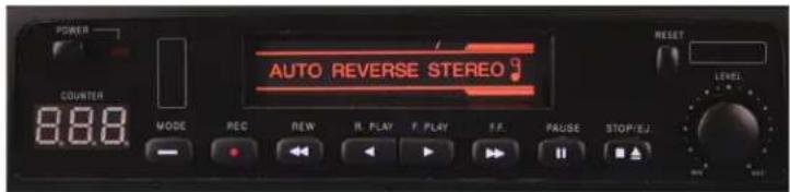
POWER: Press the POWER function to turn the power on to the Cassette Deck. Once the power is on, a small red light to the right of the POWER function will turn on, and the COUNTER display below the POWER function will light up. Press the POWER function again to turn the power off to the Cassette Deck.
TAPE COUNTER: This 3 digit illuminated display serves as a numeric reference for the user as an indicator of where on the cassette tape material is being recorded or played back. Please refer to the section below entitled 'RESET' for further information on this function
MODE: The cassette player has three operating modes- CONTINUOUS LOOP (plays side A then side B over and over until stopped), AUTO REVERSE (plays side A, then side B and stops), NORMAL (plays side A then stops).
RECORD:
Press the RECORD function to record any of the microphones, CD decks, or any other sources being reproduced by the SW905, including the CD Deck. Recording will start instantly.
REWIND: The REWIND function rewinds the tape back to the beginning of the tape and stops automatically once the beginning of the tape is reached. Press the STOP button on the Tape Player at any time during the REWIND function to manually stop REWIND.
PLAY (R. PLAY AND F. PLAY): Cassette tapes offer two sides for storing material on. As a convenience the CASSETTE DECK offers the ability to play back both sides of the cassette without the need to manually remove it and turn it over. Press the F. PLAY function to play back the side of the cassette tape facing up; press the R. PLAY function to play back the side of the tape facing down.
FAST FORWARD: The FAST FORWARD function winds the tape forward and is stopped automatically once the end of the tape is reached. Press the STOP button on the Tape Player at any time during the FAST FORWARD function to manually stop FAST FORWARD.
PAUSE: The PAUSE function puts the tape on hold without disengaging the RECORD function, or the F. PLAY or R. PLAY functions, allowing the user to temporarily stop the tape during recording or playback. Press the PAUSE function to temporarily stop the cassette tape; press the PAUSE function again to start up the cassette tape at the exact point it was paused at.
STOP/EJ (STOP/EJECT) The STOP/EJ function serves two functions. Press the STOP/EJ function once to stop the cassette tape from playing, rewinding or fast forwarding. When the cassette tape is stopped, press the STOP/EJ function to eject the cassette tape from the Cassette Deck.
RESET: Press the RESET function to reset the number in the COUNTER display to "000". This function can be used at any point during recording or playback, and is useful for creating a reference point.
DIRECTION/PLAY INDICATORS: There are two arrow heads that indicate which side of the cassette tape is active, or playing or being recorded on. The arrowhead aiming to the left indicates that the side of the tape facing down is active; the arrowhead aiming to the right indicates that the side facing up is active.
LEVEL: This controls the volume of the Cassette Deck, and allows for adjusting the volume independently of microphones plugged into Channel 3. Please see the section entitled 'INPUTS AND OUTPUTS' for further information on Channel 3 volume control.
PITCH: The PITCH tuning control allows you to change the playback speed to alter the pitch of the sound. Turning the control clockwise will increase tape speed and counter clockwise will decrease tape speed. Normal position for this control is at center detent.
PROBLEM & ITEMS TO CHECK UNIT WILL NOT TURN ON
• Is unit plugged in?
• Are batteries charged?
- Are fuses blown?
UNIT OPERATES ON AC BUT NOT BATTERY
- Check battery terminals
- Check 25A Circuit Breaker. reset if needed.
SOUND IS DISTORTED
• If OVERLOAD LED is lit, turn down volume
- If using wireless mic, is red 'Audio Peak' lit? If so, signal (such as voice) is too strong. Move microphone farther away from source.
- Turn down input source (such as keyboards, etc.) since the output of some devices may be too high
• Check for debris on speaker cone
SOUND IS MUFFLED
- Bass too high
- Treble too low
FEEDBACK: A LOUD SQUEALING, SHRILL OR HOWLING SOUND THAT IS SELF GENERATED
- Feedback occurs when a microphone is too close to the speaker or the mic volume is too high, or the microphone is pointed towards the speaker. It is also caused by sound reflecting off hard surfaces.
-
Reduce or eliminate Feedback by
-
Pointing the microphone in a different direction
- Keeping themicrophone BEHIND the speakers
Turn down the volume levels
POWER IS ON, BUT NO SOUND
• Check volume levels for each channel and main volume
- If using wireless, be sure receiver(s) and/or transmitter battery is installed and/or is on
• If using "line insert", loop must be completed.
• If mic has batteries, check batteries in microphone
• Turn on phantom power if applicable
• Check cables/connectors
WIRELESS MIC DOES NOT WORK
- Check transmitter battery is alkaline and ensure transmitter is on.
- Does yellow "signal" LED light when transmitter is turned on?
- Does the transmitter frequency group match the receiver group? (are both A or both B)
- Are the transmitter and receiver on the same channel? (0-9) Wireless mic cuts in and out
- Is unit visible (line of sight) from user? If not, move unit into view when using wireless mic.
- Does the yellow "signal" LED go out when signal drops out? Check battery in transmitter.
UNIT MAKES BUZZING NOISE
- Check cables – a damaged cable will cause this. Unplug cables one at a time until buzzing stops.
- Check for Ground loops – use a ground loop isolator where needed. (Isolator will not operate unless plugged into AC)
BATTERIES WILL NOT HOLD CHARGE
- Replace Batteries every 1-2 years if unit is not left charging when not in use.
-
A full charge is best obtained when the unit is off and plugged into the AC outlet for several hours. After a year or two the battery may need to be replaced. Batteries are available from Amplivox.
-
To replace the batteries use a phillips screwdriver and take out the 4 screws from the battery cover on the control panel. Remove the foam spacer, set aside. Pull out the batteries to access the terminals.
- Carefully hold the battery with one hand while you remove the mating connector. Replace with new battery and push mating connector of battery wire onto the corresponding color/polarity. RED = POSITIVE, BLACK = NEGATIVE.
- Place the batteries back in the compartment. Repace the foam and screw in the cover.
CD DOES NOT PLAY
• Is unit turned on?
- Be sure CD or CD-R is loaded into tray correctly.
UNIT WILL NOT PLAY CD-R/W MEDIA.
• Inspect disc for deep scratches or cracks
- Check if player is in "pause" mode
CD SKIPS
- Be sure unit is steady. If it is jarred, this may occur.
• Check for scratches on disc surface
CASSETTE TAPE DOES NOT PLAY
• Is unit turned on?
• Be sure Cassette is loaded in player
- Check if player is in "pause" mode
- Remove Cassette from player and check for entanglement
TAPE BECOMES ENTANGLED IN CASSETTE PLAYER
- Carefully remove tape from player. - Clean heads and pinch roller with rubbing alcohol and a swab or a commercially available cassette player cleaner.
NEED HELP? CALL 800-267-5486
SW915 SPECIFICATIONS
Rated power output 250W Dynamic, 132W RMS
Battery (2) 12 volt rechargeable, 7.2 AH, User accessible and replaceable
AC power 110-220 Auto sensing, 50/60 Hz,
Phantom Power Input Powers Electret condenser mics
Wireless Range Up to 200 Feet
Frequency response: 40Hz to 20Khz
Sensitivity 96dB
Equalization (tone) Separate Bass and Treble
Line output: Buffered, 600 ohm, 1/4In.-phone (pre fader)
Sensitivity for rated output:
| Balanced Microphone | -58 dBV (1.25 mVrms) |
| Balanced Line | -15 dBV (175 mVrms) |
| Unbalanced line | -20 dBV (100 mVrms) |
Unbalanced input: Hi-Z, Neutrik combo 1/4in.
Balanced Input: Lo-Z, Neutrik combo XLR
Weight: 35 lbs.
Dimensions (HWD): 23in.H x 11.5in. W x 11in. D
Warranty 6 years Electronics; 1 year on remote, Mics, Cassette Player, CD Payer, Digital Player and Rechargeable Batteries.
For future reference, please record your wireless system information here. The serial numbers appear inside the battery compartment of each transmitter and on the bottom of each receiver.
UniPak TM Body-Pack Transmitter
Handheld Dynamic Microphone Transmitter
DISCLAIMER / WARRANTY
AmpliVox Portable Sound Systems, operates a policy of continuous development. AmpliVox reserves the right to make changes and improvements to any of the products described in this document without prior notice.
Under no circumstances shall AmpliVox be responsible for any loss of data or income or any special, incidental, consequential or indirect damages howsoever caused.
The contents of this document are provided "as is". Except as required by applicable law, no warranties of any kind either express or implied, including, but not limited to, the implied warranties of merchantability and fitness for a particular purpose, are made in relation to the accuracy, reliability or contents of this document. AmpliVox reserves the right to revise this document or withdraw it at any time without prior notice.
The availability of particular products may vary by country. Please check with the distributor for your territory. In some countries there may be some restrictions in using this equipment. please check with your local radio frequency authorities.
AmpliVox products purchased in the United States are warranted for 6 years from date of purchase by AmpliVox to be free of defects and material workmanship. All accessories and the battery are warranted for 1 year. Accessories are; wireless and wired microphones, receivers and transmitters, CD players, cassette players, and digital players. In event of such defect, product will be repaired promptly without charge or at our option, replaced with a new product of equal or superior value if delivered to AmpliVox prepaid, together with proof of purchase. Prior approval from AmpliVox is required for return. This warranty excludes defects due to normal wear, abuse, shipping damage, or failure to use product in accordance with instructions. This warranty is void in the event of unauthorized repair or modification. For return and shipping information please call our customer service department at 1-800-267-5486 or outside the US, call 1-847-498-9000, Monday - Friday, 8am to 6pm, CST or email customerservice@ampli.com.

DIGITAL AUDIO TRAVEL PARTNER

AMPLIVOX PORTABLE SOUND SYSTEMS
3995 COMMERCIAL AVE., NORTHBROOK, IL 60062
PH. 800-267-5486 OR 847-498-9000
FX. 800-267-5489 OR 847-498-6691
WEB: WWW.AMPLI.COM
EMAIL: CUSTOMERSERVICE@AMPLI.COM
UPDATED 9/17/08

- DIGITAL AUDIO TRAVEL PARTNER
- USER GUIDE
- IMPORTANT SAFETY INSTRUCTIONS
- OVERLOAD
- Overload light: Lights up when volume is turned up too far and could cause audible distortion.
- 1/4-in. Phone Jacks: Can be used for outboard processors, musical instruments and recorders.
- ON-OFF SWITCH:
- MICROPHONE VOLUME:
- MASTER VOLUME:
- TREBLE:
- BASS:
- VOICE/MUSIC:
- AUDIO FUNCTIONS AND ADJUSTMENTS
- DUCKING CONTROL
- ECHO/REVERB
- PHANTOM POWER
- MICROPHONE/INSTRUMENT INPUTS:
- RECORD/LINE OUT:
- USB INTERFACE
- LINE INSERT
- SPECIAL FEATURES
- FUSES
- WARNING! RISK OF SHOCK! DO NOT OPEN UNIT NO USER SERVICEABLE PARTS INSIDE!
- REMOTE CONTROL
- REMOTE CONTROL PICKUP PATTERN
- 22-33 AND 42-44: CD PLAYER CONTROLS
- Ducking/Talk Over Section
- Reverb Section
- TRANSMITTER SETUP, CONTROLS AND FUNCTIONS
- BATTERY SELECTION:
- BELT PACK Transmitter Battery Installation:
- THE POWER SWITCH ON THE HANDHELD MICROPHONE IS BUILT INTO THE POWER/MUTE/BATTERY BUTTON, WHICH IS LOCATED ON THE BASE OF THE MICROPHONE.
- Power /Mute Battery Indicator:
- Mute Function:
- HANDLING THE DISCS:
- POWER:
- LOADING AND UNLOADING DISCS:
- NORMAL DISC PLAY:
- The CD player has been upgraded to add USB & SD Card playback and now functions with the 915 remote control.
- DIGITAL PLAYER / RECORDER S1960 (OPTIONAL EQUIPMENT)
- CASSETTE PLAYER / RECORDER S1950 (OPTIONAL EQUIPMENT)
- RECORD:
- PROBLEM & ITEMS TO CHECK UNIT WILL NOT TURN ON
- UNIT OPERATES ON AC BUT NOT BATTERY
- SOUND IS DISTORTED
- SOUND IS MUFFLED
- FEEDBACK: A LOUD SQUEALING, SHRILL OR HOWLING SOUND THAT IS SELF GENERATED
- POWER IS ON, BUT NO SOUND
- WIRELESS MIC DOES NOT WORK
- UNIT MAKES BUZZING NOISE
- BATTERIES WILL NOT HOLD CHARGE
- CD DOES NOT PLAY
- UNIT WILL NOT PLAY CD-R/W MEDIA.
- CD SKIPS
- CASSETTE TAPE DOES NOT PLAY
- TAPE BECOMES ENTANGLED IN CASSETTE PLAYER
- SW915 SPECIFICATIONS
- DISCLAIMER / WARRANTY
Brand : AmpliVox
Model : SW915
Category : Receiver