Paragon264 2TB - Voice recorder EverFocus - Free user manual and instructions
Find the device manual for free Paragon264 2TB EverFocus in PDF.


| Type de produit | Voice Recorder |
| Marque | EverFocus |
| Modèle | Paragon264 2TB |
| Capacité de stockage | 2 To (disque dur interne) |
| Formats audio supportés | MP3, WAV, WMA, PCM |
| Enregistrement | En continu, programmé, détection de son |
| Autonomie | Jusqu'à 20 heures (batterie intégrée) |
| Dimensions (L x l x H) | 120 x 80 x 25 mm |
| Poids | 300 g |
| Alimentation | Adaptateur secteur 5V/2A, USB-C PD |
| Connectivité | USB-C, Bluetooth 5.0, Wi-Fi 802.11 b/g/n |
| Microphone intégré | Oui, stéréo haute sensibilité |
| Entrée ligne | Jack 3.5 mm stéréo |
| Sortie casque | Jack 3.5 mm |
| Écran | LCD 2 pouces, rétroéclairé |
| Entretien et nettoyage | Essuyer avec un chiffon doux et sec. Éviter les solvants. |
| Sécurité | Verrouillage par mot de passe, cryptage AES-128 |
| Pièces détachées et réparabilité | Batterie et disque dur remplaçables par l'utilisateur. Service après-vente EverFocus. |
| Informations générales | Garantie 2 ans. Compatible Windows, macOS. |
Frequently Asked Questions - Paragon264 2TB EverFocus
User questions about Paragon264 2TB EverFocus
0 question about this device. Answer the ones you know or ask your own.
Ask a new question about this device
Download the instructions for your Voice recorder in PDF format for free! Find your manual Paragon264 2TB - EverFocus and take your electronic device back in hand. On this page are published all the documents necessary for the use of your device. Paragon264 2TB by EverFocus.
USER MANUAL Paragon264 2TB EverFocus
natural_image
Exterior view of a EverFocus brand electronic device with control knobs and buttons (no readable text or symbols)PARAGON264x4/264x2 Series DVR
EVERFOCUS ELECTRONICS CORPORATION
PARAGON264x4/264x2 Series DVR Instruction Manual
© 2010 EverFocus Electronics Corp
www.everfocus.com
All rights reserved. No part of the contents of this manual may be reproduced or transmitted in any form or by any means without written permission of the Everfocus Electronics Corporation.
Release Date: Mar. 2010
QuickTime is a registered trademark of the Apple Computer, Inc.
Windows is a registered trademark of the Microsoft Corporation.
Linksys is a registered trademark of the Linksys Corporation.
D-Link is a registered trademark of the D-Link Corporation.
DynDNS is a registered trademark of the DynDNS.org Corporation.
Other product and company names mentioned herein may be the trademarks of their respective owners.
Safety Precautions
- To avoid any damage, please consider the following safety warnings:
- Never place the recorder near to heaters, furnaces, other heat sources or under direct solar irradiation.
- Operate the device only in locations providing the tolerable operating temperature range 0^ 40^ / 32^ +104^ .
- Make sure that the device's ventilation slots are not covered or sheeted.
- For cleaning, make sure the device is plugged off and only use a damp cloth without acid detergent.
- Install the device only in dry and dustproof surroundings. Protect the device against any liquid's penetration.
- Avoid the penetration of any artifacts, e.g. through ventilation slots.
- Do not attempt to disassemble the appliance. To prevent electric shock, do not remove screws or covers. There are no user-serviceable parts inside. Contact qualified service personnel for maintenance. Handle the appliance with care. Do not strike or shake, as this may damage the appliance.
- Do not operate appliance with other than specified power supplies. The input power source of the power supply is 100 \~ 240 VAC.
- Avoid any affection of the device through vibrations or mechanical shock at the recorder's installation location.
- Avoid to power off DVR during playback or recording operation.

ATTENTION! This is a class A product which may cause radio interference in a domes tic environment; in this case, the user may be urged to take adequate measures.

Federal Communication Commission Interference Statement
This equipment has been tested and found to comply with the limits for a Class B digital device, pursuant to Part 15 of the FCC Rules. These limits are designed to provide reasonable protection against harmful interference in a residential installation. This equipment generates, uses and can radiate radio frequency energy and, if not installed and used in accordance with the instructions, may cause harmful interference to radio communications. However, there is no guarantee that interference will not occur in a particular installation. If this equipment does cause harmful interference to radio or television reception, which can be determined by turning the equipment off and on, the user is encouraged to try to correct the interference by one of the following measures:
•Reorient or relocate the receiving antenna.
- Increase the separation between the equipment and receiver.
- Connect the equipment into an outlet on a circuit different from that to which the receiver is connected.
- Consult the dealer or an experienced radio/TV technician for help.
FCC Caution: Any changes or modifications not expressly approved by the party responsible for compliance could void the users' authority to operate this equipment.

This Product is RoHS compliant.
The information in this manual was current upon publication. The manufacturer reserves the right to revise and improve his products. Therefore, all specifications are subject to change without prior notice. Misprints reserved. Please read this manual carefully before installing and using this unit. Be sure to keep it handy for later reference.
TABLE OF CONTENTS
1 PRODUCT OVERVIEW .... 1
1.1 FEATURES....1
1.2 PACKAGE CONTENTS.... 2
1.3 SPECIFICATIONS 4
1.4 FRONT PANEL 5
1.5 REAR PANEL 8
1.6 HDD INSTALLATION.... 10
2 INSTALLATION....11
2.1 VIDEO INPUTS/OUTPUTS INSTALLATION.... 11
2.2 AUDIO INSTALLATION 13
2.3 ALARM /CONTROL CONTACTS INSTALLATION 14
2.3.1 Alarm Input Contacts 14
2.3.2 Control Input Contact 14
2.3.3 Alarm Output Relay....15
2.4 RS-485 KEYBOARD/PTZ INSTALLATION 15
2.4.1 General RS-485 bus installation 16
2.4.2 RS-485 socket pin assignment....17
2.4.3 EKB-500 connection with network patch cable....17
2.4.4 EKB-500 connection to several DVRs....17
2.4.5 Speed Dome Installation 18
2.5 RS-232 CONNECTION 18
2.6 USB-M OUSE INSTALLATION 18
2.7 NETWORK CONNECTION 19
2.7.1 Direct PC Connection through Crossover Network Cable 19
2.7.2 Network Connection through Patch Cable....19
2.8 FINAL INSTALL PROCESS.... 20
3 MOUSE AND FRONT PANEL OPERATION 21
3.1 GENERAL USB MOUSE OPERATION.... 21
3.1.1 How to select a channel / Enable audio ....21
3.1.2 OSD Root Menu 21
3.1.3 Operation in Configuration Menu....21
3.1.4 Component Options....22
3.2 GENERAL FRONT PANEL OPERATION 24
3.2.1 How to select a channel / Enable audio ....24
3.2.2 OSD Root Menu 24
3.2.3 Front Panel Key Review....24
3.2.4 Operation in Configuration Menu....24
3.2.5 Component Options....25
4 GENERAL DVR OPERATIONS.... 27
4.1 RECORD 27
4.2 LOGIN....27
4.3 SELECT CAMERA OPERATION.... 28
4.6.1 General PTZ control 30
4.6.2 Express control PTZ....31
4.7 LAYOUT 32
4.7.1 Bring to full screen mode 32
4.8 CHANNEL SWITCHING.... 33
4.9 DISPLAY 33
4.10 SEQUENCE....34
4.11 MONITOR 34
4.12 ZOOM....35
4.13 SEARCH....36
4.13.1 Time Search....36
4.13.2 Event Search....37
4.13.3 Motion Search 38
4.14 COPY 40
4.15 LOGOUT 41
5 DVR CONFIGURATION....42
5.1 CONFIGURATION MENU....42
5.2 EXPRESS 42
5.3 CAMERA SETTING 45
5.3.1 Basic Setting....45
5.3.2 Video Adjust 47
5.3.3 Motion 48
5.3.4 Video Loss....51
5.4 RECORD & PLAY SETTING.... 52
5.4.1 Record 52
5.4.2 Built-in Cal....53
5.4.3 Play 54
5.5 ALARM & EVENT SETTING.... 55
5.5.1 Alarm....55
5.5.2 Event....57
5.6 SCHEDULE SETTING....66
5.6.1 Express Setup 66
5.6.2 Holidays 67
5.6.3 Schedule 68
5.7 NETWORK SETTING....73
5.7.1 LAN 73
5.7.2 EMAIL....74
5.7.3 DDNS 75
5.7.4 Alarm Server 77
5.8 DISPLAY SETTING....78
5.8.1 Monitor OSD....78
5.8.2 Main M/T SEQ 79
5.8.3 Call M/T SEQ....79
5.9 DISK SETTING 80
5.9.1 Disk 80
5.9.2 Lock/Format....81
5.10 SYSTEM SETTING....83
5.10.1 Date/Time 83
5.10.2 Daylight Saving....84
5.10.3 User 85
5.10.4 I/O Control....87
5.10.5 Misc....88
5.11 INFORMATION SETTING....89
5.11.1 System....89
5.11.2 Log....90
6 NETWORKING OVERVIEW 92
6.1 INTRODUCTION TO TCP/IP 92
6.2 S UBNET MASKS 92
6.3 G ATEWAY ADDRESS 92
6.4 V IRTUAL PORTS....93
6.5 P RE-INSTALLATION 93
6.6 W HAT IS YOUR NETWORK SETUP? 94
6.7 S IMPLE ONE TO ONE CONNECTION....95
6.8 D IRECT HIGH SPEED MODEM CONNECTION 100
6.9 R OUTER OR LAN CONNECTION.... 102
7 REMOTE OPERATION FROM BROWSER.... 105
7.1 CONNECTING TO DVR 105
7.2 BROWSER SECURITY SETTING 106
7.2.1 Installing ActiveX controls....106
7.2.2 Enabling ActiveX Controls....108
7.3 REMOTE LIVE VIEW 111
7.4 REMOTE PTZ CONTROL.... 112
7.5 REMOTE PLAYBACK 114
8 EVERFOCUS DDNS SETUP 115
9 LINKSYS & D-LINK PORT FORWARDING 116
9.1 LINKSYS PORT FORWARDING.... 116
9.2 D-LINK PORT FORWARDING.... 118
10 TROUBLESHOOTING 121
APPENDIX A: TIMING OF ALARM MODES....122
APPENDIX B: CHANGING RULE FOR EXPRESS SETUP.... 125
1 PRODUCT OVERVIEW
The latest EverFocus digital video recorder generation is based on H.264 compression technology, resulting in enhanced recording capacity and improved network image transmission speed with high image quality. Comprehensive features and extended event recording settings enable the almost universal application of this DVR series. The Paragon264x4/264x2 Series DVR comes with multiple control inputs. These inputs include mouse control, front panel control, IR remote control and EverFocus keyboard (EKB500) control. Mouse control is supported with the simple Graphical User Interface (GUI), offering experienced PC users the similarity of interactive command of a computer-controlled device. ←ith the GUI, users can command specific actions on the Paragon Series DVR through graphical icons and visual indicators. Simply point, click and drag the playback bar on the screen to playback our recordings in any time slot. All GUI functions can be operated via front panel, IR remote and keyboard as well. Hop on the Express Lane! The Paragon series DVR is engineered for express operations. Setup, copy, search and playback recordings in seconds with a simple “point and click” on the command icons.
1.1 FEATURES
■ H.264 Compression format
■ D1 real time recording rate and playback rate for all cameras
■ HDMI video output(1080p)
■ Pentaplex Operation (Simultaneous live, recording, playback, archiving and remote viewing)
- User friendly GUI with graphical icons and visual indicators
■ Free EverFocus DDNS Service
■ Support eSATA
■ Multiple Control Inputs: mouse/front panel/remote control/EKB500 keyboard
■ Built-in DVR calculator for fast recording estimation
■ Express Setup: Located in menu option for quick & easy installation
- Express Archive: Record video instantly while playing back (USB)
■ Express Playback: Simply point, click and drag the playback bar to view previous recordings
- Express Search: Use intuitive playback bar with a simple drag & drop operation
■ Remote configuration support from built-in web interface
- Gigabit Ethernet interface for remote network viewing and controlling
- On-screen PTZ control via mouse or front panel
■ Audio recording capabilities
■ 2 Hot Swappable HDD or 4 internal HDD
■ Built-in DVD burner
■ 3 USB 2.0 ports (2 located on front panel, 1 located on back panel) for video archive and mouse usage
■ Multi-language support
■ ←atermark capabilities to identify intentional modifications of recorded data
- Rack mountable
1.2 PACKAGE CONTENTS
■ HDD fixing bracket x 4 (Internal HDD model)
■ HDD tray x 2 (Removable HDD model)
■ DVR fixing bracket x 2
■ Remote controller x 1
- Battery x 2
■ Shockproof rubber x 16(Internal HDD model)
■ Screws x 16(Internal HDD model)
■ Expanding screws x 16(Internal HDD model)
■ SATA cable(Internal HDD model x4, Removable HDD model x 2)
■ Power cord x 1
■ Mouse x 1
■ DVR x 1
■ User manual x 1
1.3 SPECIFICATIONS
| Paragon264x4 Paragon264x2 | |||
| Channel Number 16 8 16 | |||
| Compression Format H.264 | |||
| HDMI Video Output (1080p) | Yes | ||
| Recording Rate/Resolution | 480 NTSC /400 PAL (D1) | 240 NTSC / 200 PAL (Half D1)240 NTSC /200 PAL (D1) | 480 NTSC / 400 PAL (Half D1)240 NTSC /200 PAL (D1) |
| Playback Rate/Resolution | 480 NTSC /400 PAL (D1) | 240 NTSC / 200 PAL (Half D1)240 NTSC /200 PAL (D1) | 480 NTSC / 400 PAL (Half D1)240 NTSC /200 PAL (D1) |
| 3GPP Yes | |||
| Pentaplex Operation Simultaneous Live, Recording, Playback, Archive and Remote Viewing | |||
| Video Input/ Loop/Output 16/16/Main, Call, VGA, HDMI | 8 or 16/8 or 16/Main, Call, VGA, HDMI | ||
| Matrix Output 4 Outputs (optional) | |||
| Audio Input/Output (RCA) | 16 Inputs / 1 Output 8 or 16 Inputs / 1 Output | ||
| Recording Mode Manual, Schedule and Event | |||
| Playback Search | By Date/Time and Event | ||
| Alarm In | Same as Video Input | ||
| Alarm Out | 4 Alarm Outputs | ||
| Video Pause | Yes | ||
| Video Loss Detection | Yes | ||
| Motion Detection | Yes | ||
| Event Log | Yes | ||
| ←atch Dog Timer | Yes | ||
| Internal HDD | 2 Hot swappable / 4 Internal HDD | ||
| External HDD | 1 eSATA (Hot-swappable model does not support eSATA) | ||
| Built-in DVD Burner | Slim Type DVD Burner(Optional) | ||
| User Interface | GUI(Graphical User Interface) | ||
| OS | Embedded Linux | ||
| Network/Protocol Gigabit Ethernet; TCP-IP / DHCP/ PPPoE / DDNS | |||
| Control PTZ via OSD | Yes | ||
| USB | 3 USB 2.0 ports(2 on Front Panel, 1 on Back Panel) | ||
| Schedule Setting | Support Express and Advanced Schedule Setting | ||
| User Access | 3 Levels of User Access Support | ||
| RS-232 | 9-pin D-Sub socket (male) | ||
| RS-485 1 RS485 (3 Terminal connector) |
| Power Source 100VAC~240VAC |
| Dimensions (L x ← x H) 410 x 430 x 88 mm / 16.2" x 16.9" x 3.5" |
| Temperature 0°C~40°C / 32°F~104°F (20~80% humidity) |
| Certificates CE, FCC, UL |
| Support PTZ Protocol Ever Focus, Pelco D, Pelco P, Samsung, Transparent |
1.4 FRONT PANEL
Your primary interaction with your new DVR will be through the Front Panel buttons and their corresponding buttons on the included Remote Control. Take a moment to learn where the keys are as the remainder of the manual will refer to them often.
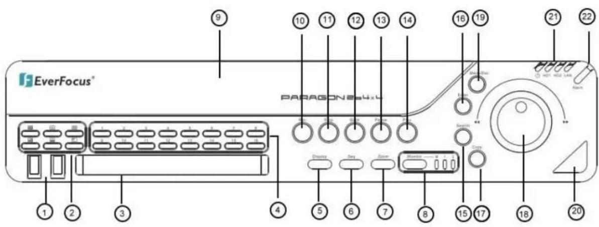
Figure 1-1 Front Panel
1) 2 x USB-2.0 port for USB mouse, USB-Flash-Drive
2) Multiview Keys:

The LED will show the selected screen layout.
NOTE: The Multiview keys are only active in Main monitor - operation.
3) DVD+RW Burner: DVD+R← drive for video data export. (for D model only)
4) Channel keys 1\~16 / 1\~8 for full screen display of selected channel. The LED will show the active channel.
5) DISPLAY: The DISPLAY key switches titles and status messages on the Screen in 4 steps. For details please consult chapter 4.9 DISPLAY.
6) SEQ: Sequence key for automatic switching of a defined camera sequence
7) ZOOM: 2x electronical zoom.
For details please consult chapter 4.12 ZOOM.
NOTE: The Zoom key is only active in Full screen at Main monitor.
8) MONITOR: The MONITOR key switches operation between MAIN and CALL. The active screen will be Main monitor when LED is in "M"; Call monitor when LED is in "1" and HDMI call monitor when LED is in "2". For more details, please refer to Chapter 4.11 MONITOR.
9) HDD: Removable SATA HDD (only for HD removable model)
NOTE: To open the HDD cover at front panel, please slightly push the cover, and it will open automatically.
10) Record: RECORD key for manual start of recording / recording standby (event recording).
LED will be ON if DVR is recording or in record standby.
11) STOP: STOP key for Playback and Record
12) BACK: Reverse Playback key
13) PAUSE: Image freeze in playback mode
14) PLAY: Playback key
15) SEARCH: The SEARCH key opens the SEARCH menu, details in chapter 4.13 SEARCH.
16) ENTER: Enter Key for menu operation and alarm acknowledge Turn camera audio ON/OFF when viewing full screen camera. For more details, please refer to Chapter 3.2.1.
17) COPY: The COPY key opens the menu for video data export, details in chapter 4.14 COPY.
18) JOG/SHUTTLE: Shuttle (outer wheel): In playback mode, use the SHUTTLE for fast forward / fast reverse playback.
JOG (inner wheel): In PAUSE mode, use the jog to move frame by frame. ←ithin menu functions, use the jog to adjust the values / parameters. Use Jog to highlight individual cameras.
Use either Shuttle or Jog to switch between MENU parameters.
19) MENU/ESC: Used to bring up Main Menu or exit from sub-Menus.
20) IR Receiver: Receiver for IR remote control
21) System LED
POWER: LED indicating power on.
HDD1: Internal/Removable HDDs in DVR
HDD2: External HDDs connected by eSATA port
LAN: LED for network traffic
22) ALARM: LED for alarm status
1.5 REAR PANEL
During initial setup you will be connecting your DVR to multiple input and output devices. This is done through the rear panel.
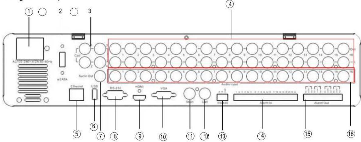
Figure 1-2 Rear Panel
① POWER: Power socket for external power supply, 100\~240VAC power source
② eSATA port: Used for external SATA HDD bay
③ Matrix outputs 1\~4 (Optional): BNC connectors for Matrix monitor outputs 1\~4.
④ Video inputs: EPARA8:
VIDEO IN (1\~8): BNC video inputs for 1 V
pp Composite video signals, automatic 75
Ohm termination (high impedance switching upon loop-through output load)
EPARA16:
VIDEO IN (1\~16): BNC video inputs for 1 V
pp Composite video signals, automatic 75
Ohm termination (high impedance switching upon loop-through output load)
⑤ LAN: RJ45 network socket
⑥ USB: For connecting USB mouse.
⑦ Audio output: Audio output
⑧ RS232 socket: 9-pin D-Sub control input for RS-232
⑨ HDMI: Connect to an HDMI-compatible unit. This HDMI-compatible unit will be treated as another call monitor. Please use HDMI cables that have the HDMI logo.
⑩ VGA: Connect to the monitor that has VGA input.
⑪ MAIN monitor: Main monitor for live and playback display and on-screen display
⑫ CALL monitor: CALL monitor output. Spot monitor for full screen live display, sequence mode and alarm camera switching
⑬ RS485 socket: For remote control via RS-485 keyboards and telemetry control
⑭ Alarm inputs: 8 (EPARA8) resp. 16 (EPARA16) alarm inputs for dry contacts, programmable NO or NC in alarm menu.
⑮ Alarm outputs: 4 x NO/NC alarm output relay.
⑯ Audio inputs: Audio inputs 1\~16(1\~8 for EPARA8)
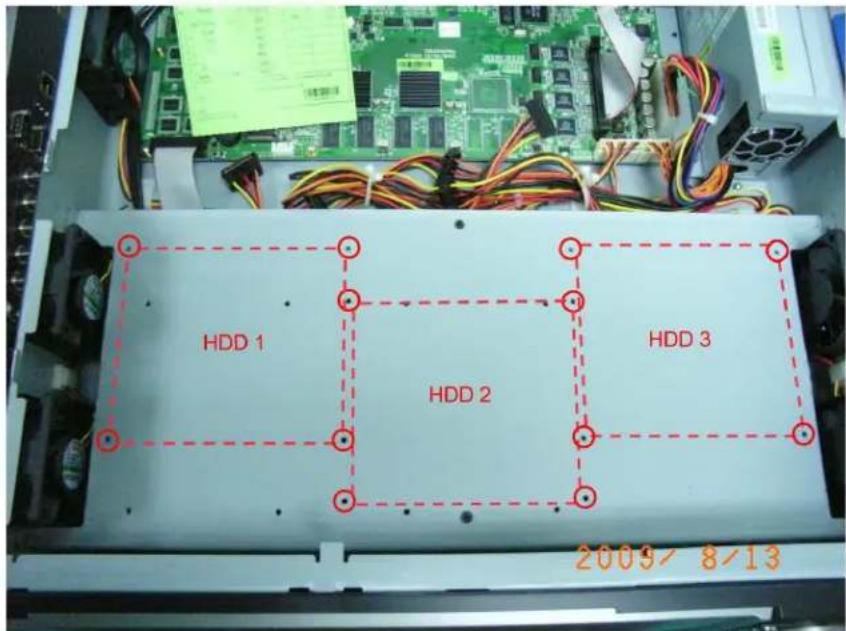
1.6 HDD INSTALLATION
Before installing the HDDs, please check the location to install HDDs. The following picture shows the location of built-in HDDs. All other screw holes are reserved for hot-swappable HDDs.
2 INSTALLATION
2.1 VIDEO INPUTS/OUTPUTS INSTALLATION
flowchart
graph TD
    A["Main Monitor"] --> B["Call Monitor"]
    A --> C["Main Monitor"]
    A --> D["Monitor at Loop - Through - Output"]
    B --> E["Main Monitor: Alternative VGA or Composite connection!"]
    C --> F["Main Monitor"]
    D --> G["Main Monitor at Loop - Through - Output"]
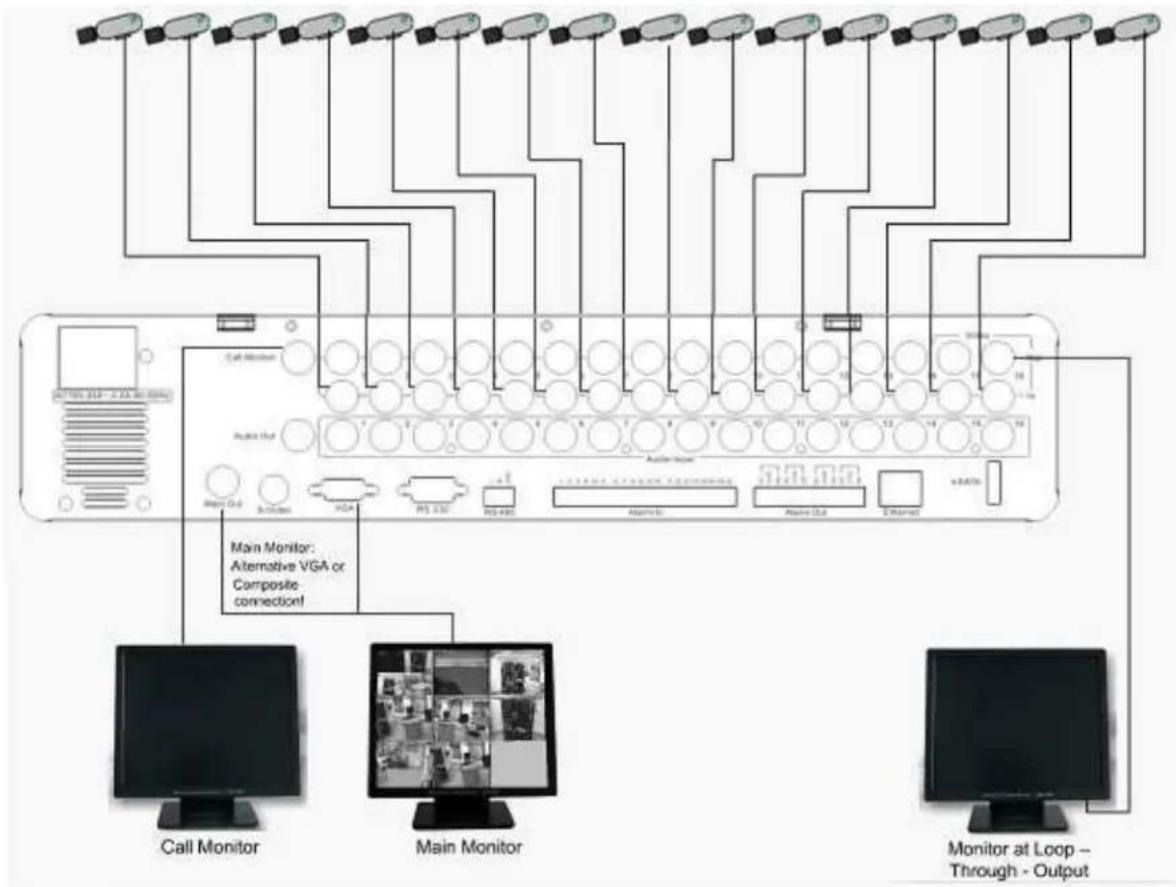
Cameras have to be cabled with 75 Ohm video cable, e.g. RG-59, RG-12 and suitable BNC plugs.
Due to inappropriate absorbability, 50 Ohm coax cable (e.g. RG58), antenna cable and further types of coax cable are not suitable.
All connected video sources must provide a 1 Vpp NTSC/EIA or PAL/CCIR standard video signal (depending on DVR version PAL / NTSC).
←hen interconnecting transmission lines (twisted pair, fibre optics, radio) to the video inputs, make sure all receivers are accurately calibrated.
The Main monitor can be connected to BNC, Composite, or VGA monitor output.
NOTE: VGA monitor must support 800x600@60Hz resolution.
For local DVR operation, MAIN monitor connection is required. Call monitor connection is optional.
2.2 AUDIO INSTALLATION
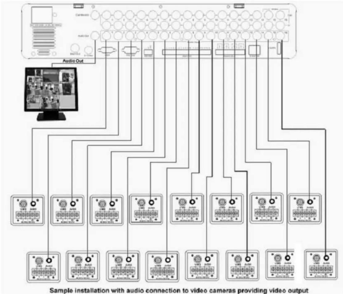
flowchart
graph TD
    A["Sample installation with audio connection to video cameras providing video output"] --> B["Audio Out"]
    B --> C1["Control knobs: 1-12"]
    B --> C3["Audio meters: 0-12"]
    B --> C4["Control knobs: 1-12"]
    B --> C5["Control knobs: 1-12"]
    B --> C6["Control knobs: 1-12"]
    B --> C7["Control knobs: 1-12"]
    B --> C8["Control knobs: 1-12"]
    B --> C9["Control knobs: 1-12"]
    B --> C10["Control knobs: 1-12"]
    B --> C11["Control knobs: 1-12"]
    B --> C12["Control knobs: 1-12"]
    B --> C13["Control knobs: 1-12"]
    B --> C14["Control knobs: 1-12"]
    B --> C15["Control knobs: 1-12"]
    B --> C16["Control knobs: 1-12"]
    B --> C17["Control knobs: 1-12"]
    B --> C18["Control knobs: 1-12"]
    B --> C19["Control knobs: 1-12"]
    B --> C20["Control knobs: 1-12"]
    B --> C21["Control knobs: 1-12"]
    B --> C22["Control knobs: 1-12"]
    B --> C23["Control knobs: 1-12"]
    B --> C24["Control knobs: 1-12"]
    B --> C25["Control knobs: 1-12"]
    B --> C26["Control knobs: 1-12"]
    B --> C27["Control knobs: 1-12"]
    B --> C28["Control knobs: 1-12"]
    B --> C29["Control knobs: 1-12"]
    B --> C30["Control knobs: 1-12"]
    B --> C31["Control knobs: 1-12"]
    B --> C32["Control knobs: 1-12"]
    B --> C33["Control knobs: 1-12"]
    B --> C34["Control knobs: 1-12"]
    B --> C35["Control knobs: 1-12"]
    B --> C36["Control knobs: 1-12"]
    B --> C37["Control knobs: 1-12"]
    B --> C38["Control knobs: 1-12"]
    B --> C39["Control knobs: 1-12"]
    B --> C40["Control knobs: 1-12"]
    B --> C41["Control knobs: 1-12"]
    B --> C42["Control knobs: 1-12"]
    B --> C43["Control knobs: 1-12"]
    B --> C44["Control knobs: 1-12"]
    B --> C45["Control knobs: 1-12"]
    B --> C46["Control knobs: 1-12"]
    B --> C47["Control knobs: 1-12"]
    B --> C48["Control knobs: 1-12"]
    B --> C49["Control knobs: 1-12"]
    B --> C50["Control knobs: 1-12"]
    B --> C51["Control knobs: 1-12"]
    B --> C52["Control knobs: 1-12"]
    B --> C53["Control knobs: 1-12"]
    B --> C54["Control knobs: 1-12"]
    B --> C55["Control knobs: 1-12"]
    B --> C56["Control knobs: 1-12"]
    B --> C57["Control knobs: 1-12"]
    B --> C58["Control knobs: 1-12"]
    B --> C59["Control knobs: 1-12"]
    B --> C60["Control knobs: 1-12"]
    B --> C61["Control knobs: 1-12"]
    B --> C62["Control knobs: 1-12"]
    B --> C63["Control knobs: 1-12"]
    B --> C64["Control knobs: 1-12"]
    B --> C65["Control knobs: 1-12"]
    B --> C66["Control knobs: 1-12"]
    B --> C67["Control knobs: 1-12"]
    B --> C68["Control knobs: 1-12"]
    B --> C69["Control knobs: 1-12"]
    B --> C70["Control knobs: 1-12"]
    B --> C71["Control knobs: 1-12"]
The DVRs provide 16/8 audio inputs and 1 audio output.
The inputs are designed for max. 1 v_pp @ 20 KOhm input.
The installation has to be effected with audio coax cable and RCA plugs.
The output provides a max. 1 vpp @ 20 KOhm output line audio signal and may be connected to e.g. a monitor's audio input. The direct connection of (passive) speakers is not supported.
ATTENTION: The direct connection of a non-amplified microphone is not supported (a microphone amplifier is required).
AUDIO RECORDING FUNCTIONALITY:
Audio recording is activated / deactivated in the RECORD menu (chapter 5.4.1) for all channels.
Audio of all channels is always recorded together with (each) video and is independent of the image recording rate.
During playback/live, use the JOG to select camera and press ENTER to turn audio ON or OFF.
2.3 ALARM / CONTROL CONTACTS INSTALLATION
The alarm inputs can be used for recording start or recording rate adjustment. Furthermore, alarm reactions such as camera switching to monitors, buzzer, e-mail and network alarm are available. 4 alarm output relays can be switched if required.
Additionally the DVR provides 4 x TTL - level control outputs with similar functionality as the relay outputs.
2.3.1 Alarm Input Contacts
EPARA8 provides 8 alarm inputs, EPARA16 provides 16. All inputs are programmable N.O. (Normal Open) or N.C. (Normal Closed)
Inputs have to be switched by dry contacts.
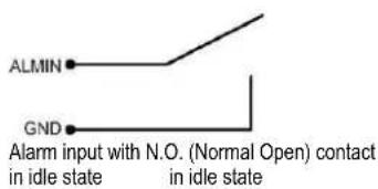
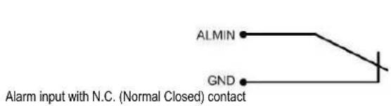
All settings are programmed in the ALARM menu (chapter 5.5.1).
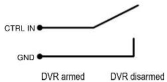
2.3.2 Control Input Contact
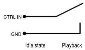
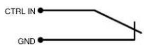
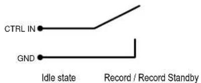
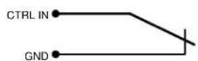
The Control Input CTRL IN is a N.O. (Normal Open) contact. Changing to N.C. is not possible.
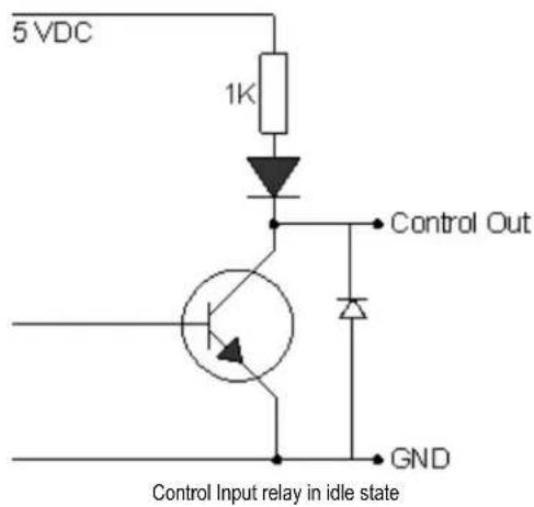
The Control Input Contact CTRL IN is defined in I/O Control menu (■chapter 5.10.4) for following possible functions:
- Playback: Playback is active as long the contact is closed. This function is helpful in combination with the "Quickplay" function ( chapter 5.4.3)
- Record: The input switches to Record (or Record Standby) as long the contact is closed.
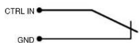
- Armed / Disarmed: If the contact is closed, the DVR will switch off alarm (alarm contact and motion alarm) operation. System alarm events are always active.
2.3.3 Alarm Output Relay
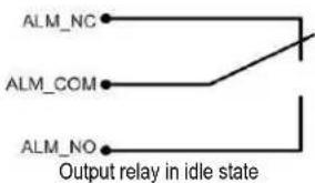
The relay outputs provide either Normally Open or Normally Closed dry contacts.
2.4 RS-485 keyboard / PTZ Installation
All functions can be remote-controlled by the EKB-500 universal keyboard. Using the EEPROM protocol, digital video recorders, keyboards and speed domes can be installed on one single RS-485 bus. One system can comprise up to 8 keyboards.
2.4.1 General RS-485 bus installation
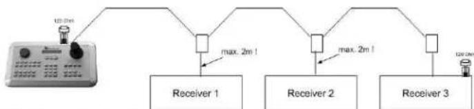
The EKB-500 keyboard uses an RS-485 simplex wiring; the signal is transferred via a single twisted pair line. CAT5 network cable is recommended, UPT version (unshielded) is sufficient for normal application. A shielded cable should be used if the installed cables are expected to be highly susceptible to interferences. The number of devices installed in one bus is limited to 32, and the maximum cable length is 1200m. Both of these can be expanded using a signal distributor (see below).
Both the first and the last device in series should be terminated with 120 Ohm resistance in order to minimize line reflections.

flowchart
graph TD
    A["Device"] -->|100.00mA| B["Receiver 1"]
    A -->|100.00mA| C["Receiver 2"]
    A -->|100.00mA| D["Receiver 3"]
RS-485 bus serial wiring
Cable length from box to device („Stubs“) has to be limited to 2m using connector boxes.
flowchart
graph TD
    A["100 MHz"] --> B["Receiver 1"]
    A --> C["Receiver 2"]
    A --> D["Receiver 3"]
    B --> E["max. 2m!"]
    C --> F["max. 2m!"]
    D --> G["100 MHz"]
RS-485 bus serial wiring with connector boxes and connection cable
A direct RS-485 bus star wiring is not supported unless using a signal distributor (see below).

flowchart
graph TD
    A["Device with sensor"] --> B["Receiver 1"]
    A --> C["Receiver 2"]
    A --> D["Receiver 3"]
Improper RS-485 bus star wiring
An RS-485 signal distributor may be used to use a star wiring configuration.
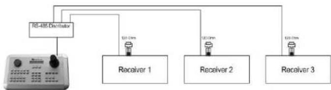
flowchart
graph TD
    A["RS-485 Distributor"] --> B["Receiver 1"]
    A --> C["Receiver 2"]
    A --> D["Receiver 3"]
    B -->|120.0ms| E
    C -->|120.0ms| F
    D -->|120.0ms| G
Star wiring with RS-485 signal distributor
An RS-485 distributor can also be used to increase the maximum number of devices on the bus as well as the total range. Each distributor output provides another RS-485 bus. This allows each output to extend an additional 1200m, and it also enables the additional connection of 31 further devices to each output (the output itself represents one device).
The maximum system expandability depends on the RS-485 address range of the installed devices.
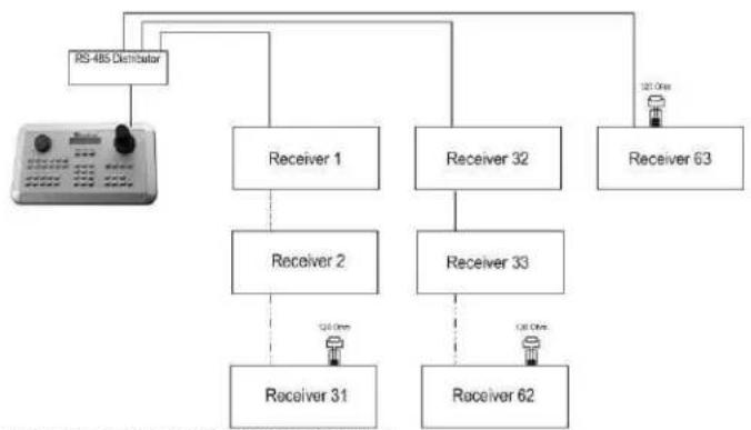
flowchart
graph TD
    A["RS-485 Distributor"] --> B["Receiver 1"]
    A --> C["Receiver 2"]
    A --> D["Receiver 32"]
    A --> E["Receiver 63"]
    B --> F["Receiver 31"]
    C --> G["Receiver 33"]
    D --> H["Receiver 62"]
    E --> I["Output Device"]
System expansion with RS-485 signal distributor
ATTENTION: Most signal distributors are unidirectional! This means that the signal only flows from the input towards the outputs. Therefore, e.g. the interconnection of several keyboards is not possible with these types of signal distributor!
2.4.2 RS-485 socket pin assignment
The following RS485 pin assignment as follow:
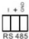
2.4.3 EKB-500 connection with network patch cable
For a simple, short distance installation, recorder and keyboard can directly be connected using a standard CAT5 network cable (patch cable, uncrossed!).
2.4.4 EKB-500 connection to several DVRs
For long distance installations connecting several DVRs, please use signal distributor to connect
For further details on keyboard connection, please refer to the EKB-500 manual.
RS-485 port communication settings are configured in the I/O CONTROL menu (Chapter 5.10.4 System Setup: I/O - control).
2.4.5 Speed Dome Installation
Speed dome or telemetry receiver pan/tilt/zoom control is available through web browser or the optional PowerCon software if the DVR is connected to a network. Local telemetry control is provided by USB - mouse control or by the optional EKB-500 keyboard.
Supported protocols: EverFocus, Pelco-D, Pelco-P, Samsung, Transparent
Required DVR settings: RS-485 receiver address in CAMERA menu

ATTENTION: Some Pelco-D / -P protocol domes and receivers require an address offset of -1, i.e. the address assigned to the dome / receiver in the DVR camera menu must be 1 below the address set in the dome / receiver itself!
2.5 RS-232 Connection
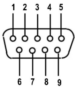
| Pin Function |
| 2 T→D |
| 3 R→D |
| 5 Ground |
2.6 USB-Mouse installation
Connect the USB mouse to one of the 2 USB ports. (This can be done while DVR is powered on)
NOTE: Recommended mouse types are Logitech® and Microsoft® wired USB wheel-mouse. ←ireless USB mouse is not supported.
2.7 NETWORK CONNECTION
This section only describes physical connection to an Ethernet network. This step must be completed before the DVR's can connect to the network. There are two basic types of connection:
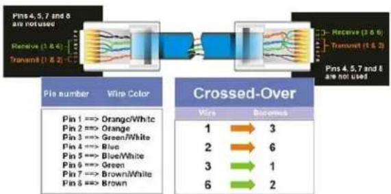
2.7.1 Direct PC Connection through Crossover Network Cable
The point-to-point connection of DVR and PC requires a crossover (crossed) network cable. This type of connection is ONLY used for direct connection to a single PC. Make sure that the PC is equipped with a 10/100/1000 Mbps compatible network connection.

Figure 2-1 Direct PC Connection
flowchart
graph LR
    A["Pin number"] --> B["Orange/White Pin 1 => Orange"]
    A --> C["Green/White Pin 2 => Orange"]
    A --> D["Blue/White Pin 3 => Green"]
    A --> E["Brown/White Pin 4 => Blue"]
    A --> F["Brown/White Pin 5 => Blue"]
    A --> G["Brown/White Pin 6 => Green"]
    A --> H["Brown/White Pin 7 => Brown/White"]
    A --> I["Brown/White Pin 8 => Brown"]
    J["Pin number"] --> K["Orange/White Pin 1 => Orange"]
    J --> L["Green/White Pin 2 => Orange"]
    J --> M["Blue/White Pin 3 => Blue"]
    J --> N["Blue/White Pin 4 => Blue"]
    J --> O["Green/White Pin 5 => Green"]
    J --> P["Brown/White Pin 6 => Brown"]
    Q["Pin number"] --> R["Orange/White Pin 1 => Orange"]
    Q --> S["Green/White Pin 2 => Orange"]
    Q --> T["Blue/White Pin 3 => Blue"]
    Q --> U["Brown/White Pin 4 => Blue"]
    Q --> V["Brown/White Pin 5 => Blue"]
    W["Pin number"] --> X["Brown/White Pin 1 => Orange"]
    W --> Y["Brown/White Pin 2 => Orange"]
    W --> Z["Brown/White Pin 3 => Blue"]
    W --> AA["Brown/White Pin 4 => Blue"]
    W --> AB["Brown/White Pin 5 => Blue"]
    AC["Pin number"] --> AD["Brown/White Pin 1 => Orange"]
    AC --> AE["Brown/White Pin 2 => Orange"]
    AC --> AF["Brown/White Pin 3 => Blue"]
    AC --> AG["Brown/White Pin 4 => Blue"]
    AC --> AH["Brown/White Pin 5 => Blue"]
    AI["Pin number"] --> AJ["Brown/White Pin 1 => Orange"]
    AI --> AK["Brown/White Pin 2 => Orange"]
    AI --> AL["Brown/White Pin 3 => Blue"]
    AI --> AM["Brown/White Pin 4 => Blue"]
    AI --> AN["Brown/White Pin 5 => Blue"]
    AO["Pin number"] --> AP["Brown/White Pin 1 => Orange"]
    AO --> AQ["Brown/White Pin 2 => Orange"]
    AO --> AR["Brown/White Pin 3 => Blue"]
    AO --> AS["Brown/White Pin 4 => Blue"]
    AO --> AT["Brown/White Pin 5 => Blue"]
    AU["Pin number"] --> AV["Brown/White Pin 1 => Orange"]
    AU --> AW["Brown/White Pin 2 => Orange"]
    AU --> AX["Brown/White Pin 3 => Blue"]
    AU --> AY["Brown/White Pin 4 => Blue"]
    AU --> AZ["Brown/White Pin 5 => Blue"]
    BA["Pin number"] --> BB["Brown/White Pin 1 => Orange"]
    BA --> BC["Brown/White Pin 2 => Orange"]
    BA --> BD["Brown/White Pin 3 => Blue"]
    BA --> BE["Brown/White Pin 4 => Blue"]
    BA --> BF["Brown/White Pin 5 => Blue"]
    BG["Pin number"] --> BH["Brown/White Pin 1 => Orange"]
    BG --> BI["Brown/White Pin 2 => Orange"]
    BG --> BJ["Brown/White Pin 3 => Blue"]
    BG --> BK["Brown/White Pin 4 => Blue"]
    BG --> BL["Brown/White Pin 5 => Blue"]
    BM["Pin number"] --> BN["Brown/White Pin 1 => Orange"]
    BM --> BO["Brown/White Pin 2 => Orange"]
    BM --> BP["Brown/White Pin 3 => Blue"]
    BM --> BQ["Brown/White Pin 4 => Blue"]
    BM --> BR["Brown/White Pin 5 => Blue"]
    BS["Pin number"] --> BT["Brown/White Pin 1 => Orange"]
    BS --> BU["Brown/White Pin 2 => Orange"]
    BS --> BV["Brown/White Pin 3 => Blue"]
    BS --> BW["Brown/White Pin 4 => Blue"]
    BS --> BX["Brown/White Pin 5 => Blue"]
    BY["Pin number"] --> BZ["Brown/White Pin 1 => Orange"]
    BY --> CA["Brown/White Pin 2 => Orange"]
    BY --> CB["Brown/White Pin 3 => Blue"]
    BY --> CC["Brown/White Pin 4 => Blue"]
    BY --> CD["Brown/White Pin 5 => Blue"]
    CE["Pin number"] --> CF["Brown/White Pin 1 => Orange"]
    CE --> CG["Brown/White Pin 2 => Orange"]
    CE --> CH["Brown/White Pin 3 => Blue"]
    CE --> CI["Brown/White Pin 4 => Blue"]
    CE --> CJ["Brown/White Pin 5 => Blue"]
    CK["Pin number"] --> CLB["Brown/White Pin 1 => Orange"]
    CK --> CMB["Brown/White Pin 2 => Orange"]
    CK --> CNB["Brown/White Pin 3 => Blue"]
    CK --> COB["Brown/White Pin 4 => Blue"]
    CK --> CPB["Brown/White Pin 5 => Blue"]
    COB["Pin number"] --> CPB["Brown/White Pin 1 => Orange"]
    COB --> CPB["Blue/Brown/White Pin 2: Orange; Green/Brown/White Pin 3: Green/Brown/White Pin 4: Blue; Green/Brown/White Pin 5: Blue; Green/Brown/White Pin 6: Green/Brown/ White; Green/Brown/Brown: Brown/Brown/Brown"] & CX["Pin number"] & CX["Crossed-Over"] & CX["Crossed-Over"] & CX["Crossed-Over"] & CX["Crossed-Over"] & CX["Crossed-Over"] & CX["Crossed-Over"] & CX["Crossed-Over"] & CX["Crossed-Over"] & CX["Crossed-Over"] & CX["Crossed-Over"] & CX["Crossed-Over"] & CX["Crossed-Over"] & CX["Crossed-Over"] & CX["Xue / Bus"] & CX["Bus / Bus"] & CX["Bus / Bus"] & CX["Bus / Bus"] & CX["Bus / Bus"] & CX["Bus / Bus"] & CX["Bus / Bus"] & CX["Bus / Bus"] & CX["Bus / Bus"] & CX["Bus / Bus"] & CX["Bus / Bus"] & CX["Bus / Bus"] & CX["Bus / Bus"] & CX["Bus / Bus"] & CX["Bus / Bus"] & CX["Bus / Bu"] & CX["Bus / Bus"] & CX["Bus / Bus"] & CX["Bus / Bus"] & CX["Bus / Bus"] & CX["Bus / Bus"] & CX["Bus / Bus"] & CX["Bus / Bus"] & CX["Bus / Bus"] & CX["Bus / Bus"] & CX["Bus / Bus"] & CX["Bus / Bus"] & CX["Bus / Bus"] & CX["Bus / Bus"] & CX["Bus / Bus"]
Pinout of crossover-cable
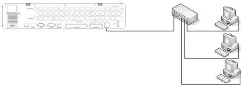
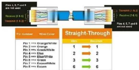
2.7.2 Network Connection through Patch Cable
The connection to an existing network requires a normal patch cable (straight-through). The illustration shows the connection to a network switch, router, or modem.
flowchart
graph TD
    A["Server"] --> B["Switch"]
    B --> C["Computer 1"]
    B --> D["Computer 2"]
    B --> E["Computer 3"]
Figure 2-2 Network Connection through Patch Cable
flowchart
graph LR
    A["Pls 4, 5, 7 and 8 are not used"] --> B["Receive (3 & 6)"]
    B --> C["Transmit (1 & 2)"]
    C --> D["Pls 4, 5, 7 and 8 are not used"]

    E["Pls number Wire Color"] --> F["Pin 1 => Orange/White"]
    E --> G["Pin 2 => Orange"]
    E --> H["Pin 3 => Green/White"]
    E --> I["Pin 4 => Elus"]
    E --> J["Pin 5 => Elua/White"]
    E --> K["Pin 6 => Green"]
    E --> L["Pin 7 => Brown/White"]
    E --> M["Pin 8 => Brown"]

    N["Straight-Through"] --> O["Vire"]
    O --> P["1 => 1"]
    O --> Q["2 => 2"]
    O --> R["3 => 3"]
    O --> S["6 => 6"]
Pinout of straight patchcable
2.8 FINAL INSTALL PROCESS
Once you have completed the basic wiring connections, you are ready to turn on the DVR. Simply plug in the power source. The PO←ER LED will light up if power is normal. Once the system has finished loading, you can begin to set up the menu options for the DVR.
3 MOUSE AND FRONT PANEL OPERATION
Paragon 264x4/264x2 series DVR supports multiple sources to control the DVR. It can be controlled with a mouse, the front panel, an EKB500, the handheld remote control, or serial command from RS232 port.
This chapter will cover the basic operation using mouse and front panel.
3.1.1 How to select a channel / Enable audio
- In a view consisting of more than one channel, user can select a channel by clicking once on desired channel screen. The selected screen will be highlighted by white frame.
- Double clicking on a channel screen will display full screen of this channel.
- To enable audio out, click audio icon(ex: 📄) at lower side of the screen. This system can have only one audio out for one camera at a time. Click this button to select a camera for audio out, or to select none audio-out mode.
3.1.2 OSD Root Menu
- Right-click the mouse to obtain DVR control bar (see Figure 3-1 OSD Root Menu). ←hen you move the mouse over each icon, the appropriate title will be displayed on top of the control bar.

Figure 3-1 OSD Root Menu
- Click on any icon to perform that action. These actions are covered in detail in Chapter 4.
- Click the "→" in the top-right corner to close the DVR control bar.
3.1.3 Operation in Configuration Menu
The Main menu (shown in Figure 3-2 OSD Menu) is divided into 3 main sections.
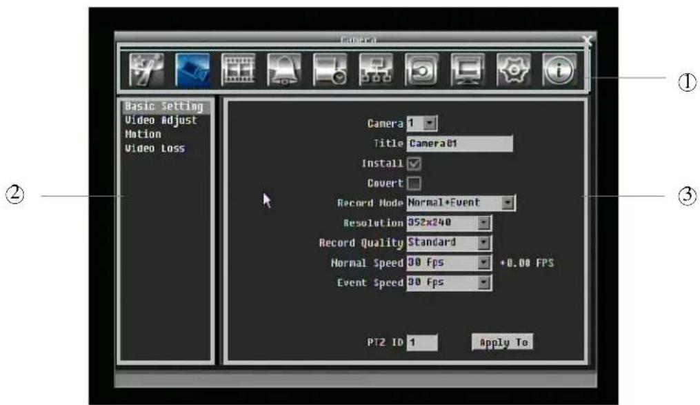
Figure 3-2 OSD Menu
① In section 1, there are ten setup options available. Move the mouse over an icon and click to select it.
② In section 2, the categories for the selected icon will be displayed. Click on a word to select it.
③ In section 3, all the details for the selected option will be available. Click on a field to make changes.
3.1.4 Component Options
The following are examples of different fields available in the Configuration menu.

Textbox: Click on the box and an on-screen keyboard will appear. (see
below)

Dropdown box: Click on the down arrow to see all selections, then
directly click on an option to select it.
Check box: Click on the box to enable it (checked) or disable it (unchecked).

Button: Click the button to execute the function.
Bar: Click and hold on the bar to adjust the cursor Left or Right.
\* Note about on-screen keyboard:
Click on a button to input that character.
The buttons on the right and bottom have the following functions:
| Delete Delete the letter |
| Done Confirm the selection |
| All Caps Switch to capital letters |
| Space Enter a space |
| ← Move to left |
| → Move to right |
| Cancel Cancel and exit from the keyboard |
3.2 GENERAL FRONT PANEL OPERATION
3.2.1 How to select a channel / Enable audio
- In a view consisting of more than one channel, turning Jog or Shuttle can scroll through each channel that is displayed. The selected channel will be highlighted by white frame.
- ←hile one channel is selected, click "Enter" button to turn Audio On/ Off.
3.2.2 OSD Root Menu
- Press "Menu" key to obtain DVR control bar. Use Jog or Shuttle to scroll over each icon. The title for each icon will be displayed on top of the control bar.
- Press "Enter" key on any icon to perform that action. These actions are covered in detail in Chapter 4
- Press "Menu" to close the DVR control bar.
3.2.3 Front Panel Key Review
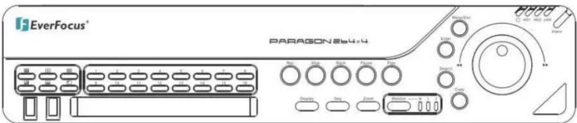
The basic principle of front panel operation is to use Jog and Shuttle to navigate among the menu items. Use "Enter" key to confirm a selection or enter the next level menu. Press "Menu" key to enter the Main Menu or exit from the current level of the menu.
3.2.4 Operation in Configuration Menu
Press "Menu" and press "Enter" with "Configuration" icon highlighted to bring up Configuration menu.
NOTE: If password is active, you will need to log in first. Refer to "4.2 LOGIN" for information on logging in. The menu (shown in Figure 3-3 (OSD Menu)) is divided into 3 main sections.
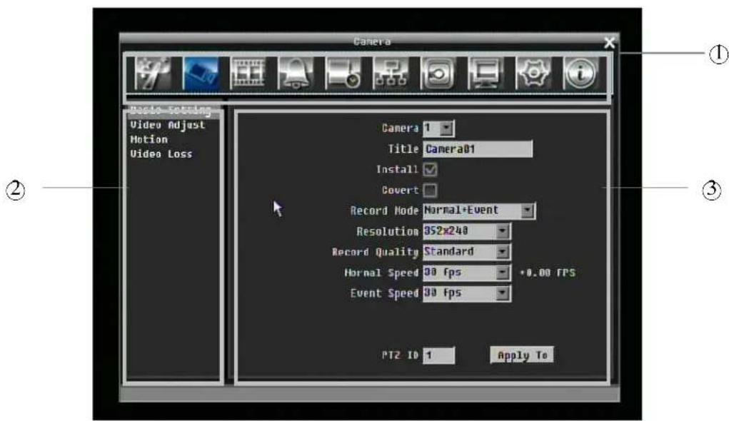
Figure 3-3 (OSD Menu)
① In section 1, there are ten setup options available. Use Jog or Shuttle to highlight an icon and press "Enter" to select it.
② In section 2, the main options for the selected icon will be displayed. Use Jog to highlight an option and press "Enter" to select it.
③ In section 3, all the details for the selected option will be available here. Use Jog to move between items and press "Enter" to make changes.
Note: press "Menu" button to go back to the previous menu section.
3.2.5 Component Options

Textbox: Press Enter key and an on-screen keyboard will appear. (see
below)

Dropdown box: Press "Enter" key to show the available options. Use Jog
to highlight the desired option and press "Enter" again to select it.

Check box: Press "Enter" key on a setting to enable it (checked) or disable it (unchecked).

Button: Press "Enter" key to execute the function.
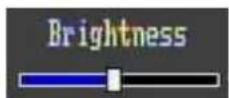
Bar: Press "Enter" key to activate the slider, then use Jog to adjust the setting. Press size the changes.
4 GENERAL DVR OPERATIONS
This chapter introduces the operations on major functions including playback, layout change, sequence, triplex operations, copy, and search.
4.1 RECORD
By default, the DVR will always be in record mode. ←hen the DVR is turned on, it will start to record.
The exceptions are:
- DVR will not record any uninstalled cameras (Refer to section 5.3.1 for more detail)
- If a schedule is active, DVR will follow the record settings of the schedule.
4.2 LOGIN
In order to access Paragon options, users may be asked to log in for authority identification. To log in, follow these steps.
- Click (or press "Enter" key) on the Configuration icon to bring up the following screen:
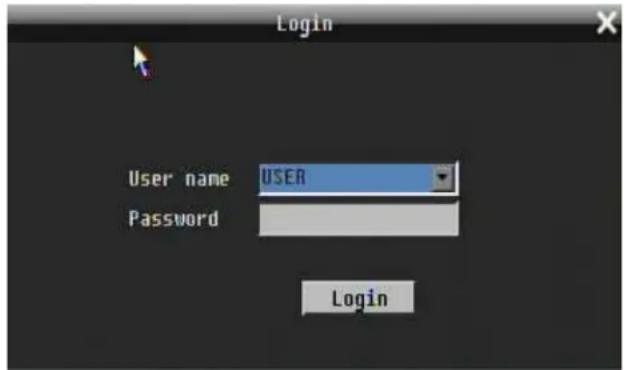
Figure 4-1 Login page
- Select the user name from the drop-down list and input the password. The defaults are:
User name: admin (lower case)
Password: 11111111
+ To input password by mouse: click the password field to bring up the on-screen keyboard (see Figure 4-2 On-screen Keyboard). Click on each button to input the desired characters for the password. ←hen finished, click "Done" on the on-screen keyboard to confirm the password.
+ To input password using front panel: press "Enter" key to show the on-screen keyboard (see Figure 4-2 On-screen Keyboard). Use Jog or Shuttle to highlight each character and press "Enter" key on front panel to input the selected characters. ←hen finished, highlight "Done" and press "Enter" key on front panel to confirm the password.
+ Click (or press "Enter" key) on "Login" button to log in to the system.
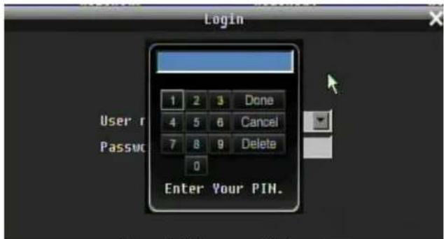
Figure 4-2 On-screen Keyboard
4.3 SELECT CAMERA OPERATION
Paragon is a pentaplex DVR, user can control each camera individually. User can control camera which has been selected. For camera selection:
Mouse: Right-click the screen, there will show a white frame on screen if the camera has been selected. ←hen in split display mode, press same layout icon in layout menu to select all.
Front panel: Use Jog to change selection. Turn Jog one more step to select all camera at last turn(E→: when camera16 is selected, turn jog one more step can select all)
Use Jog to select a camera and press "Enter" key to switch audio output to that camera. An audio icon will appear on the screen.
4.5 PLAYBACK
Playback bar is the fastest way to get exact time which users want to see. Playback bar allows user to see time line and current playback indicator, user can click time line to move the indicator to the position which they want to see. The operation is as follow:
To playback:
By mouse: Right-click to bring up the menu bar and click on to enter Playback Menu.
By front panel: Press

to enter Playback Setup Menu.
A playback bar will show as the figure below:
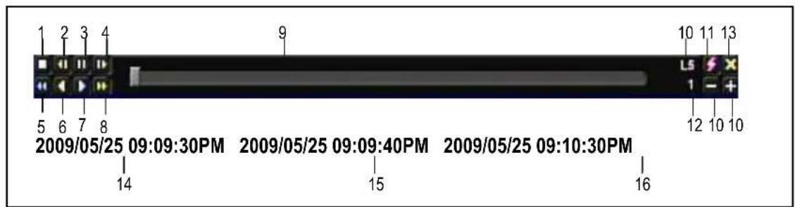
- Stop key: press to stop playback
- Slow Reverse key: press to slow reverse playback
- Pause key: press to pause playback
- Slow Forward key: press to slow forward playback
- Fast Reverse key: press to fast reverse playback
- Reverse key: press to reverse playback
- Forward key: press to forward playback
- Fast Forward key: press to fast forward playback
- Time bar: Move the cursor on the time bar to select time to playback(The start time and end time of time bar is showed below)
- “+” and “-” signs are used to adjust time scale level. Press “+” or “-” to select between L1 \~ L5. ←hen change level, the start time and end time of time bar will change)
L1: ←hole time bar is 2 days
L2: ←hole time bar is 30 hours.
L3: ←hole time bar is 1 hour.
L4: ←hole time bar is 10 minutes.
L5: ←hole time bar is 1 minute. - Express copy: Press to start express copy when camera is in playback (only one camera)
- Playback speed
- Press “→” to close playback bar.
- Start time of time bar (the most left point of time bar)
- Current playback time (the time which indicator locate)
- End time of time bar (the most right point of time bar)
4.6 PTZ
4.6.1 General PTZ control
Right-click to bring up the menu bar and click on to enter PTZ Menu.
The following actions can be performed using the PTZ Menu:
- Use Direction Arrows (up, down, left, right) to move the camera to the desired direction and angle.
- In Zoom option, Click "Z+" to zoom closer or "Z-" to zoom farther away.
- In Focus option, click "F+" to increase the focus or click "F-" to decrease the focus.
- In Iris option, you can increase the amount of light by clicking "I+" or decrease it by clicking "I-".
- To program a preset position
a. Move PTZ camera to the specified position
b. Click "Preset" button
c. Click the number of the desired position (This will be displayed in the box)
d. Click "Set" button
- Steps to jump to a preset position
a. Click "Preset" button
b. Click the number of the desired position
c. Click "Go" button
- Shortcut steps for presets #1-9
a. Click digit 1-9 button without clicking any other buttons
- Steps to delete a preset position
a. Click "Preset" button
b. Click the number of the desired position
c. Click "Delete" button
- Steps to run Auto Pan
a. Click "Auto Pan" button
- Pattern Operation (Pattern is the "0" Tour in Everfocus and Pelco PTZ cameras)
a. Click "Pattern" button
- Steps to run a tour
a. Click "Tour" button
b. Click the number of the desired tour
c. Click "Go" button
- Steps to remove a tour
a. Click "Tour" button
b. Click the number of the desired tour
c. Click "Delete" button

Click "C" to clear the digit in cell
Click "X" at top-right corner to close PTZ menu.
Click "Exit" to leave PTZ function.
4.6.2 Express control PTZ
←hen PTZ menu is closed, the mouse cursor will change to a different icon in different areas of the screen. User can control PTZ direction, zoom, and focus by clicking directly on screen.
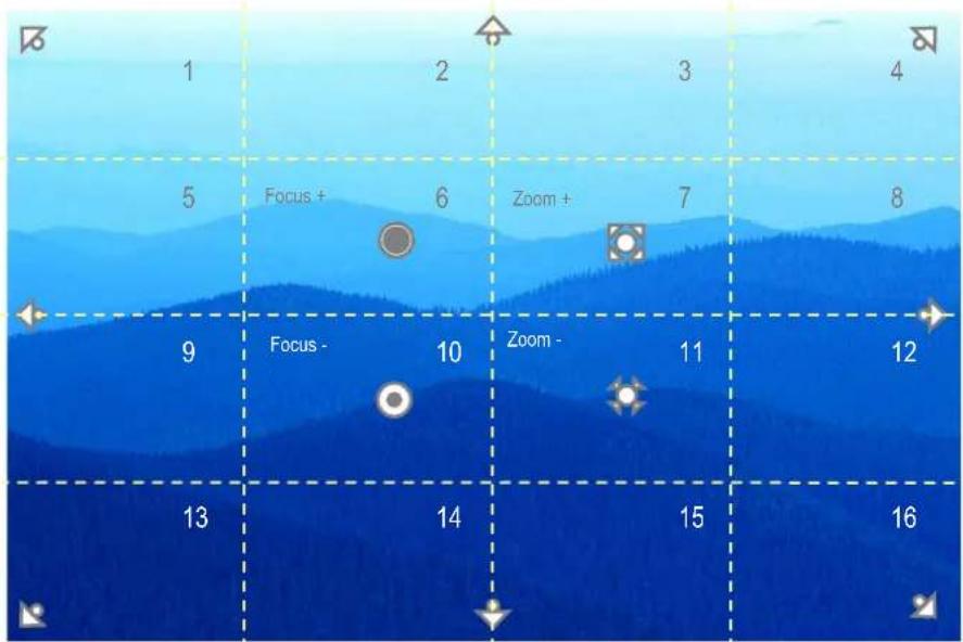
Figure 4-3 Express Control PTZ
The screen is divided into a 4x4 grid. The function of each section is defined as below:
• 1: PTZ pan/tilt left and up
• 2, 3: PTZ tilt up
• 4: PTZ pan/tilt right and up
• 5, 9: PTZ pan left
• 8,12: PTZ pan right
• 13: PTZ pan/tilt left and down
• 14, 15: PTZ tilt down
• 16: PTZ pan/tilt right and down
- 6: Focus closer
• 10: Focus further
- 7: Zoom in
• 11: Zoom out
4.7 LAYOUT
The DVR has a total of seven display modes available. The different available layouts are shown below:
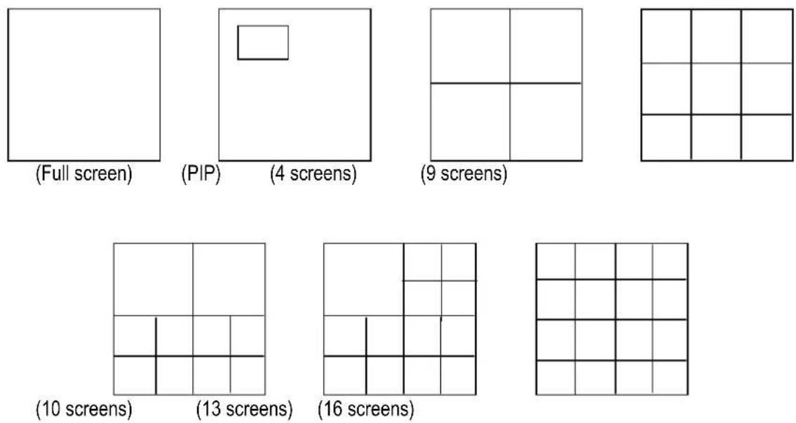
NOTE: PIP display is not available in Playback mode
To change layout, follow the steps below:
By mouse: Right-click to bring up the menu bar and click to scroll through each display option.
By front panel: Push the appropriate display button on the front of the DVR (see red marker in below image).
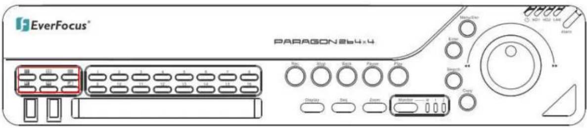
4.7.1 Bring to full screen mode
By mouse: Double left-click on the selected channel to put that camera in full screen mode.
By front panel: Press any channel key to bring that channel to full screen mode.
4.8 CHANNEL SWITCHING
Use this function to change channel position
- Select one camera
- Press Channel button

- Click on the channel number you wish to switch on channel bar. The display of channel will be switched.

E→: Select camera1 and enter Channel menu and choose "2", than camera1 will show on position of camera2, camera2 will show on position of camera1
4.9 DISPLAY
- Press Display button on menu by using mouse or press "Display" button on the front panel.
- Press once to show camera information. Please see the following table for status representation.
| Recording PlaybackFast forward Fast backward | Back pause | ||||
| [H223]Alarm | [0Y4]Motion |  Video loss Video loss | Express copy |  Audio out Audio out | |
- Press again to show status information. Please see the following table for status representation.
 Alarm Alarm |  Audio 1~16 Audio 1~16 |  Control call monitor Control call monitor |  Event Event |  Fan failure Fan failure |  HD failure HD failure | |
 HD temp. too high HD temp. too high |  Monitor 1 status Monitor 1 status |  Motion Motion |  New firmware New firmware |  No network No network |  Record in HD1 Record in HD1 | |
 Record in HD2 Record in HD2 |  Seq. Seq. |  Video loss Video loss |
-
Press again to show both status information and camera information.
-
Press again to hide all information.
4.10 SEQUENCE
- By mouse: Click Sequence button to enter the auto sequential switching mode.
- By front panel: Click Sequence button on front panel to enter the auto sequential switching mode.
4.11 MONITOR
The DVR can connect to main monitor and call monitors simultaneously, but only one of them can be controlled at one time. This feature allows user to switch control between three monitors.
Switch control by using a mouse
Click on "Monitor" button in menu or click global information icon " " to switch control to call monitor.
“”button means the main monitor is selected. “”button means the call monitor 1 is selected.
“” means the call monitor 2 (HDMI monitor) is selected.
Switch control from front panel
Click "Monitor" button on front panel to switch control of monitor. The light right next to "Monitor" button indicates which monitor is active: "M" indicates main monitor, "1" indicates call monitor 1, "2" indicates call monitor 2.
Operation of Call Monitor OSD
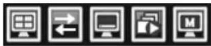
View: Click this button to view different layouts.
Change: Switch channels.
Display: Turn OSD display on/ off.
Sequence: Turn sequence on/off.
Monitor: Click this button switch control to main monitor.
4.12 ZOOM
-
Make sure no cameras are in playback mode
-
Select one camera
-
Right-click to bring up the menu bar and click button, or press "Zoom" key on front panel.
-
←hen in ZOOM mode, the mouse cursor will change to a different icon in different areas of the screen. User can control PTZ direction, zoom, and focus by clicking directly on screen:
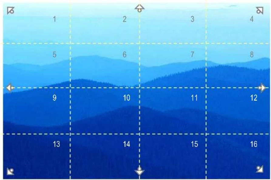
Figure 4-4 Zoom Express Control
The screen is divided into a 4x4 grid. The function of each section is defined as below:
• 1: Left and up
• 2, 3: Up
• 4: Right and up
• 5, 9: Left
• 8,12: Right
• 13: Left and down
• 14, 15: Down
• 16: Right and down
• 6, 7, 10, 11: Not used
4.13 SEARCH
By mouse: Right-click to bring up the menu bar and click to enter Search Menu.
By front panel: Press "Search" key to enter Search Menu directly.
4.13.1 Time Search
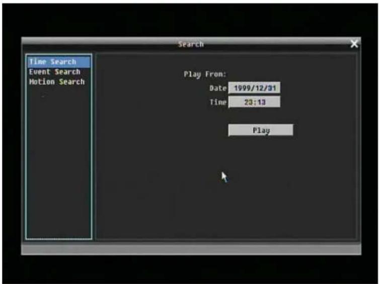
Figure 4-5 Search Menu – Time Search
Play From: Select the time to be searched by choosing the Date and Time.
Click on the "Play" button to start search. The DVR will automatically play the video being searched. DVR will play the nearest time if there is no data in selected time.
In search playback mode, press stop button to come back to search menu.
4.13.2 Event Search
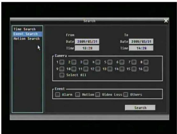
Figure 4-6 Search Menu – Event Search
From: Select starting date and time
To: Select ending date and time.
Camera: Select which cameras to search for.
Event: Select which event type(s) to search for. Choose from Alarm, Motion, Video Loss, or Others. Click on the "Search" button to start searching. The search results will be shown as a list of events.
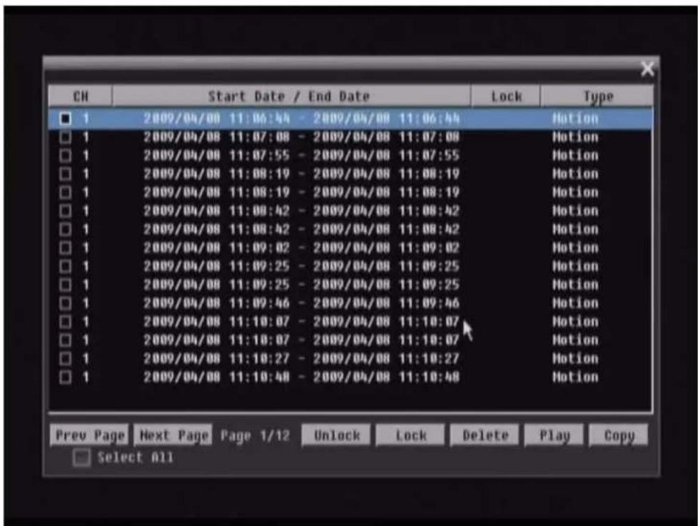
Prev Page: Go to previous page.
Next Page: Go to next page
Unlock: Unlock the item if the item is locked
Lock: Lock the item (After click Lock button, the selected item will show Locked or Partial)
Delete: Delete item if it is not locked
Play: Playback selected item
Copy: Copy selected item
In Lock status, there will show "Partial" in some case, it means there has a time period which has been locked in whole search result time period.
4.13.3 Motion Search
In order to perform a Motion Search, motion must be enabled first (see "Chapter 5.3.3").
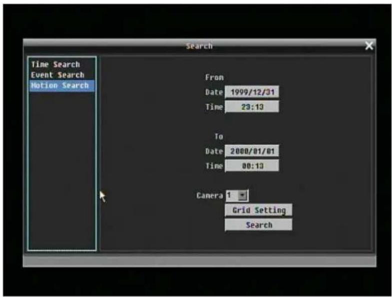
Figure 4-7 Search Menu – Motion Search
From: Select motion search starting date/time.
To: Select motion search ending date/time.
Camera: Select camera number to be searched.
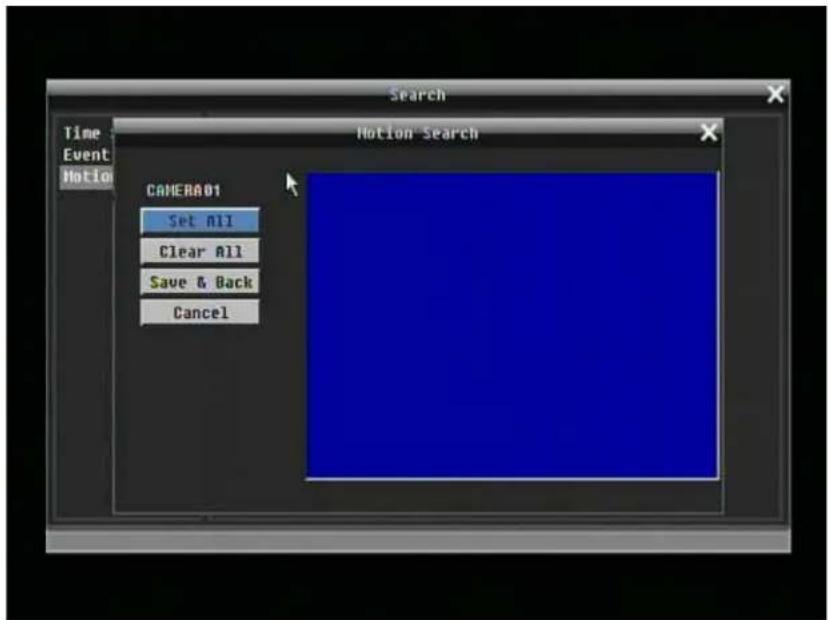
Figure 4-8 Search Menu – Set Grid
Grid Setting:
Choose which areas of the motion grid will be included in the search. The areas you set in motion search must also be active in the motion settings of the Camera Setting Menu. Use the mouse to drag your desired area. Press "Set All" button to select the entire area. Press "Clear All" to deselect the entire area. Press "Save & Back" to save the motion grid setting and go back to Motion Search menu. Press "Cancel" to skip edition
Press "Search" button to start searching.
4.14 COPY
To bring up Copy menu:
By mouse: Right-click to bring up the menu bar and click on to enter Copy Menu.
By front panel: Press "Copy" key to enter Copy Menu directly.
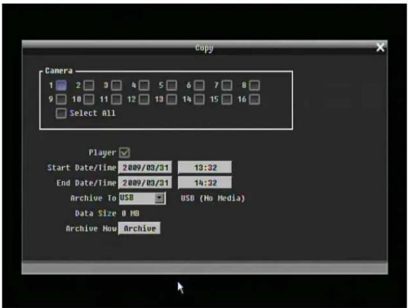
Figure 4-9 Copy Menu
Camera: Select which cameras will be archived. Choose "Select All" to select all the cameras.
Player: Check the box to include the ePlayer program as part of the copy.
Start Date/Time: Select the starting date/time to be archived.
End Date/Time: Select the ending date/time to be archived.
Archive To: Select whether you want to copy to USB or DVD.
Data Size: Shows the estimated total size for the selected time period. (Paragon DVR is Linux base DVR, when you check the space of USB sticker by DVR or PC, the space may have a little bit different between PC and DVR)
Archive Now: Press "Archive" button to start archiving.
4.15 LOGOUT
Right-click to bring up the menu bar and click button to bring up the Logout Confirmation window (see Figure 4-10).
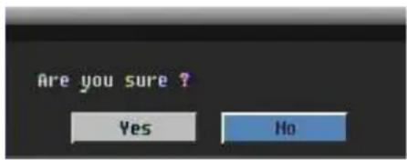
Figure 4-10 Logout Confirmation window
Press "Yes" button when you are ready to logout from the system. You will need to login again before accessing any other options.
5 DVR CONFIGURATION
This chapter will walk you through the DVR Menu Settings step by step and show you how to set the DVR for your specific application.
-
To bring up the Main Menu, press the "Menu/Esc" key on the front panel or right-click with the USB mouse to bring up the OSD menu bar.
-
Press "Enter" or left-click on the "Configuration" icon " [icon] " to enter configuration menu.
5.2 EXPRESS
Figure 5-1 Express Menu is a screen shot of the EXPRESS SETTING MENU. This menu is used to configure express setting for all 16 cameras. For example, if user selects Event Only in Record Mode and presses Apply button, all 16 cameras will be set to Event only. If user selects Blank in Recording Mode and presses Apply button, 16 cameras will keep their own current record modes without changing.
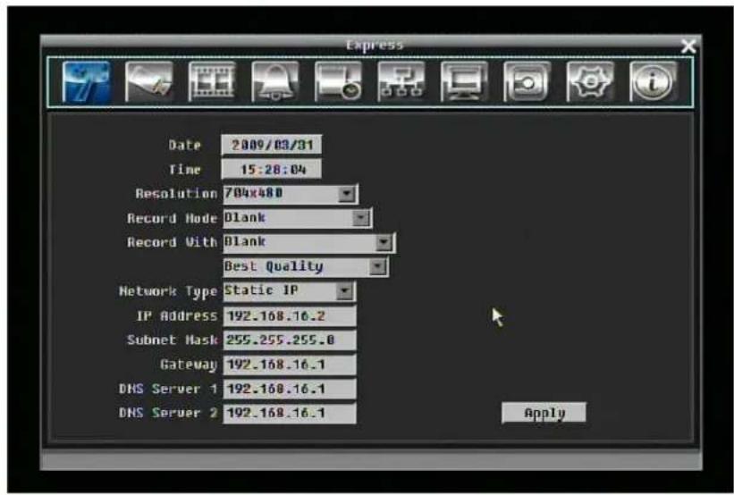
Figure 5-1 Express Menu
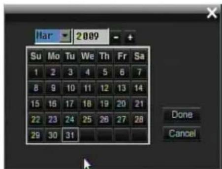
Date: Set the current date of DVR.
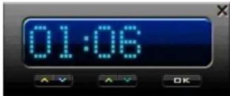
Time: Set the current time of DVR.
Resolution: Select recording resolution based on video format.
NTSC: 704x480 / 704x240 / 352x240
PAL: 704x576 / 704x288 / 352x288
Record Mode:
Blank: No change for Record mode
Normal+Event: Normal recording plus event recording.
Event Only: Event recording only.
Schedule Rec: Schedule recording.
Record With:
Blank: No change for Record with
Max. Recording Days: Set the maximum recording days. Available selection will be shown in the next column, including 1, 3, 5, 7, 14, 20, 30, 40, 50 and 60 day. DVR will auto adjust relative settings for 16 cameras to fit the selected max recording day. For more detail, please refer to APPENDI→ B: CHANGING RULE FOR E→PRESS SETUP
Preset Settings: Select preset setting or recording quality. Available options are Best Quality, Standard and Extended Record in the next column. For more detail, please refer to APPENDI→B: CHANGING RULE FOR E→PRESS SETUP
Network Type:
Fixed IP: User can set a fixed IP for network connection.
DHCP: DHCP server in LAN will automatically assign IP for network connection.
PPPoE:
IP Address: This field shows the current IP Address for the DVR. A Fixed IP address must be set manually If DHCP or PPPoE is selected, this value will be assigned automatically.
Subnet Mask: This field shows the subnet mask for your network so the DVR will be recognized within the network. If DHCP or PPPoE is selected, this value will be assigned automatically.
Gateway: This field shows the gateway for your network so the DVR will be recognized within the network. If DHCP or PPPoE is selected, this value will be assigned automatically.
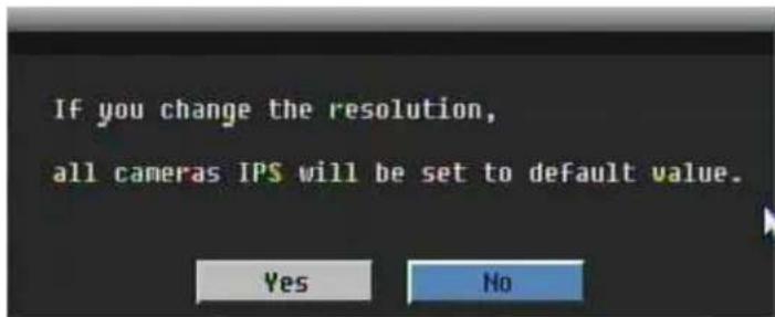
Apply: Press "Apply" button to save and apply Express settings to DVR. The system will automatically adjust recording frame rate according to settings. The following message will pop up, press YES to change Resolution, Recording frame rate and Quality depending on your express setting.
5.3 CAMERA SETTING
Figure 5-2 is a screen shot of the CAMERA SETTING MENU. This menu is used to configure individual camera settings.
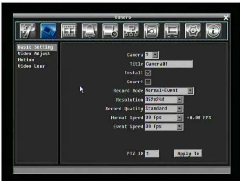
Figure 5-2 Camera Menu-Basic Setting
5.3.1 Basic Setting
Camera: Select the camera number.
Title: The title setting allows you to assign a title to selected camera. Each title supports up to 16 characters. The on-screen keyboard will appear when you click the title option.
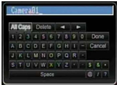
Install: Check the box to enable the current camera. To take full advantage of the DVR's recording abilities, any unused cameras should have this option disabled.
Covert: Check the box to hide the camera picture in live and sequence modes. However, the image will still be recorded and can be played back by any user who has playback rights.
Record Mode: 2 record modes are available.
Normal + Event: This recording mode includes continuous and event recording.
Event Only: Video will be recorded only when events occur.
Resolution: Select recording resolution based on video format.
NTSC: 704x480 / 704x240 / 352x240
PAL: 704x576 / 704x288 / 352x288
Record Quality: Select an image quality for recording. There are five different qualities available: Superior, High, Standard, Basic and Low. A higher image quality uses more HDD space.
Normal Speed: Frame rate in images per second (IPS) for continuous recording. The speed is limited to the maximum recording rate of the DVR (displayed in the bottom left corner) divided by the number of installed cameras. If the resolution option is changed, the unit of this field will also be changed.
Recording capacity for all 16 cameras (shown next to the Normal Speed field): The number here indicates the remaining recording capacity available for all 16 cameras. ←hen this number is positive, it means there is still recording capacity. If this number is negative, it means the recording capacity has been exceeded, and the user must lower Normal Speed or Resolution. This number must be positive before saving the changes. Otherwise, a pop-up window will display “Total FPS exceed maximum recording rate, discard changes!” and the settings for all cameras will return to previous values.
Event Speed: Frame rate in images per second (IPS) for event recording.
PTZ ID: ←hen using a PTZ Camera, this ID must match the ID used by the connected camera in order to control the camera using the DVR. Click "Done" to confirm selection, "Cancel" to cancel selection.
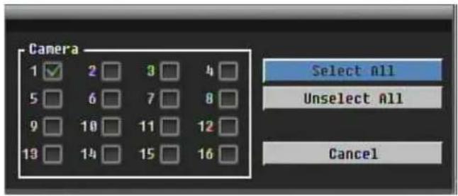
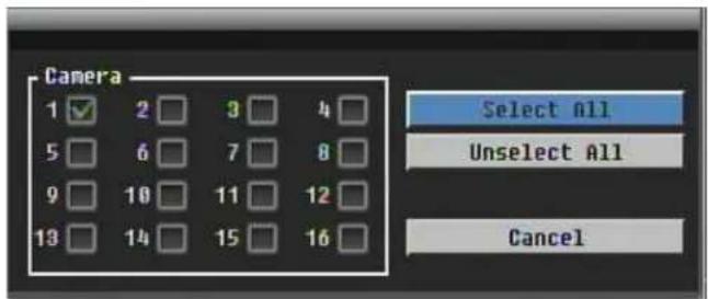
Apply To: This button can be used to copy the recording settings to other cameras. Select which cameras you wish to copy to. "Select All" selects all cameras, "Unselect All" deselects all cameras. Click "OK" to copy the settings or "Cancel" to exit without copying.
5.3.2 Video Adjust
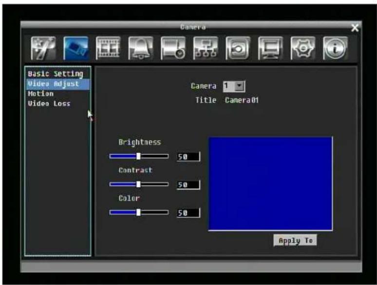
Figure 5-3 Camera Menu – Video Adjust
Camera: Select the camera you wish to adjust. "Title" will change to the name of the selected camera.
Brightness: Adjusts how bright/dark the picture appears. If details appear to be lost in the shadows or darker regions, try increasing the Brightness. If the image appears too saturated or if the colors appear overwhelmed by glare, try decreasing the Brightness.
Contrast: Adjusts the total amount of light output from the display. If details are lost or lines appear distorted, try decreasing the contrast.
Color: Adjusts the amount of color information in the picture.
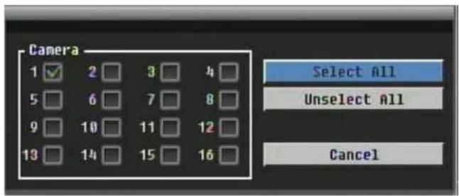
Apply To: This button can be used to copy the video settings to other cameras. Select which cameras you wish to copy to. "Select All" selects all cameras, "Unselect All" deselects all cameras. Click "OK" to copy the settings or "Cancel" to exit without copying.
5.3.3 Motion
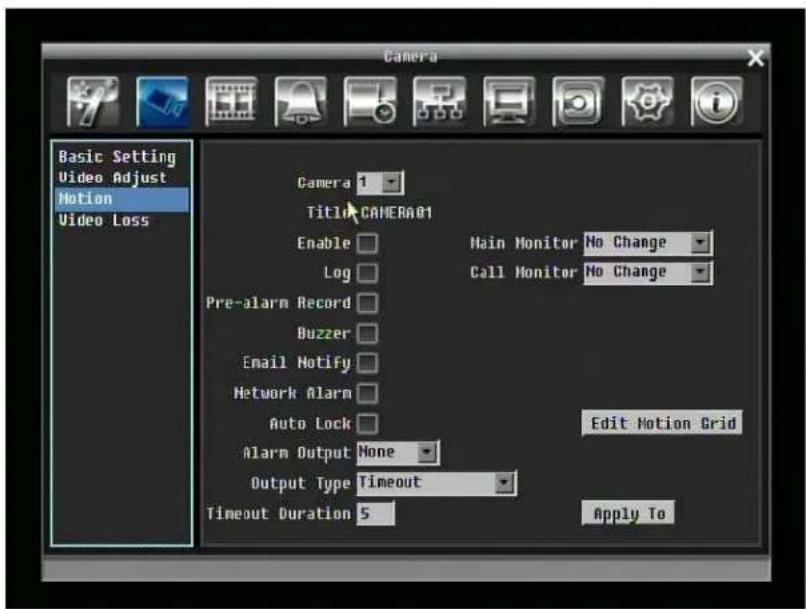
Figure 5-4 Camera Menu – Motion
Camera: Select the camera you wish to adjust. "Title" will change to the title name of the selected camera.
Enable: Check box to enable motion detection. Other motion options will not be available unless this feature is selected.
Log: Check box to record motion events in the log.
Main Monitor: Monitor display options when a motion event occurs.
No change: No change on the main monitor display.
Full screen: A full screen of the active camera will display on the main monitor.
Call Monitor: Monitor display options when a motion event occurs.
No change: No change on the call monitor display.
Full screen: A full screen of the active camera will display on the call monitor.
Pre-alarm Record: Check box to record several moments before the motion event. (Pre-alarm recording rate will follow "Normal" frame rate setting)
Buzzer: Check box to enable buzzer when a motion event is triggered.
Email Notify: Check box to send email notification when a motion event is detected.
Network Alarm: Check box to send out a network alarm to client PC when motion occurs. (requires PowerCon software and setting up Alarm Server in Network Setup menu)
Auto Lock: Check the box and the events will be recorded in the write protected segment of the Hard Disk. (DVR will lock a period of time when alarm happen, the length of time will depend on DVR setting)
Alarm Output: This will transmit a signal through one of the alarm outputs. It can be set to either "NONE" (not active), "1", "2", "3", or "4".
Output Type: Output action when motion is triggered.
Timeout: Alarm output lasts for the set time duration.
Permanent: Alarm will remain on until user presses "Enter" key on front panel.
Transparent: Alarm output continues as long as there is a motion event.
Trans+Timeout: Alarm output continues until event ends, then lasts for the set time duration.
Timeout Duration: Time duration selectable from 1 to 150 seconds.
Edit Motion Grid: Press this button to edit the motion grid (See Figure 5-5 Camera Menu – Motion Grid Setting).
Sensitivity: Set the threshold value for sensitivity. Select from 1 (lowest) to 10 (highest).
Min Area: To avoid false detections by small objects this value defines, how many grids have to be detected for generating a motion event. Select a value between 1 (default) to 5 grids.
Delay: Filter function for avoiding false alarms (set to 1 for the easiest trigger)
Preview: Turn off display for motion grid
Set All: Press this button to select the entire area.
Clear All: Press this button to clear all the grids selected.
Save & Back: Press this button to save the motion grid setting and return to motion setting menu.
Cancel: Press this button to cancel all changes and return to motion setting menu.
How to select motion grid by mouse:
- Select left-up grid 2. Select right-down grid. 3. The area between left-up and right-down grid will be selected.
![Motion CAMERA01 Mode: Preview Sensitivity 6 Min Area 1 Delay 1 Preview Set All Clear All Save & Back Cancel Sensitivity [10]:Highest, [1]:Lowest](/content/2026/05/959603/images/8ce8b5105df8641d5d58443b621f673d190f94de3f97f1493f93d70306896e59.jpg)
Figure 5-5 Camera Menu – Motion Grid Setting
Apply To: This button can be used to copy the motion settings to other cameras. Select which cameras you wish to copy to. "Select All" selects all cameras, "Unselect All" deselects all cameras. Click "OK" to copy the settings or "Cancel" to exit without copying.
5.3.4 Video Loss
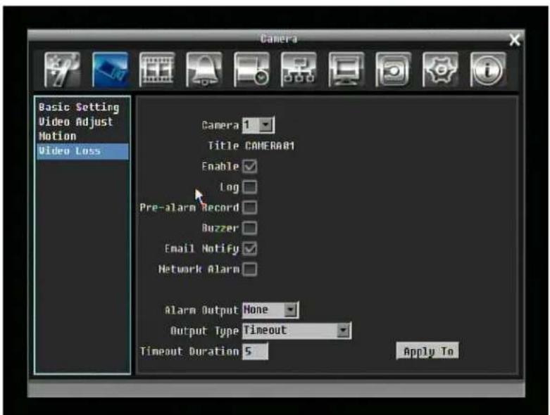
Figure 5-6 Camera Menu – Video Loss
Camera: Select the camera you wish to adjust, "Title" will change to the title name of the selected camera.
Enable: Check box to enable Video Loss.
Log: Check box to record video loss events in the log.
Pre-alarm Record: Check box to record several moments before the video loss. (Pre-alarm recording rate will follow "Normal" frame rate setting)
Buzzer: Check box to enable buzzer when a video loss event occurs.
Email Notify: Check box to enable email notification when a video loss event occurs.
Network Alarm: Check box to send out a network alarm to client PC when video loss occurs. (requires PowerCon software and setting up Alarm Server in Network Setup menu)
Alarm Output: This will transmit a signal through one of the alarm outputs. It can be set to either "NONE" (not active), "1", "2", "3", or "4".
Output Type: Output action when alarm is triggered.
Timeout: Alarm output lasts for the set time duration.
Permanent: Alarm will remain active until user presses "Enter" key on front panel.
Transparent: Alarm output continues as long as there is a video loss.
Trans+Timeout: Alarm output continues until event ends, then lasts for the set time duration.
Timeout Duration: Time duration selectable from 1 to 150 seconds.
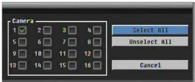
Apply To: This button can be used to copy the video loss settings to other cameras. Select which cameras you wish to copy to. "Select All" selects all cameras, "Unselect All" deselects all cameras. Click "OK" to copy the settings or "Cancel" to exit without copying.
5.4 RECORD & PLAY SETTING
Figure 5-7 is a screen shot of the RECORD & PLAY SETTING MENU. This menu is used to configure basic recording and playback settings.
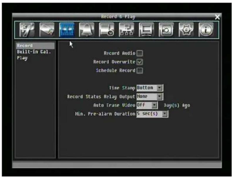
Figure 5-7 Record & Play Menu
5.4.1 Record
Record Audio: Check the box to record audio.
Record Overwrite: Check the box and disk will begin overwriting when full.
Schedule Rec.: Use schedule recording mode.
For Schedule recording, the only way to stop schedule recording is to turn schedule recording off. Pressing any keypad on front panel to change schedule recording will not work during scheduling record mode. ←hen schedule recording is disabled, DVR will auto turn on recording
Time Stamp: Select if the time and date will display while recording. Choose from Top, Bottom, or Off.
Record Status Relay Output: Select from "NONE", "1", "2", "3", or "4".
Auto Erase Video: The hard drive will automatically erase after the selected number of days. To use the maximum hard drive space, choose "OFF".
5.4.2 Built-in Cal.
The built-in record period calculator can give a rough estimation of the total recording time of the DVR with current settings.
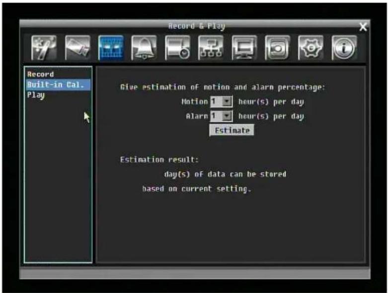
Figure 5-8 Record & Play Menu-Built-in Cal.
Motion: Enter the expected amount of hours per day using motion record.
Alarm: Enter the expected amount of hours per day using alarm records.
If total amount of Motion and Alarm hour more than 24 hours, it will assume that total motion and alarm hours is 24 hours.
Click on the ESTIMATE" button to display the result at the bottom of the screen:
" xx days of data can be stored based on current setting"
5.4.3 Play
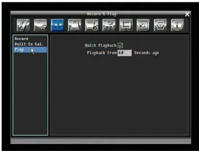
Figure 5-9 Record & Play Menu - Play
Quick Playback: Check the box to enable quick playback function.
Playback From X Seconds ago: ←hen the DVR is put into playback, it will begin playing from the selected time. Choose from 60 to 3600 seconds.
5.5 ALARM & EVENT SETTING
Figure 5-10 is a screen shot of the ALARM & EVENT SETTING MENU. This menu will walk you through alarm and event setup.
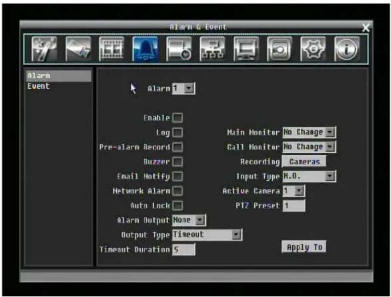
Figure 5-10 Alarm & Event Menu - Alarm
5.5.1 Alarm
Alarm: Select the alarm number from 1 to 16.
Enable: Check box to enable alarm.
Log: Check box to record alarm events in the log.
Pre-alarm Record: Check box to record several moments before the alarm event. (Pre-alarm recording rate will follow "Normal" frame rate setting)
Buzzer: Check box to enable buzzer when an alarm occurs.
Main Monitor: Monitor display options when a motion occurs.
No change: No change on the main monitor display.
Full screen: A full screen of the active camera will display on main monitor.
Call Monitor: Monitor display options when a motion occurs.
No change: No change on the call monitor display.
Full screen: A full screen of the active camera will display on call monitor.
Recording: Select which cameras will start recording when alarm happens.
Email Notify: Check box to enable email notification when an alarm occurs.
Input Type: This field is to change the type of alarm trigger.
N.O.: Normal Open contact.
N.C.: Normal Close contact.
Network Alarm: Check box to send out a network alarm to client PC when motion occurs. (requires PowerCon software and setting up Alarm Server in Network Setup menu)
Active Camera: This field is for assigning the alarm to a specific camera. For example if you had an external motion detector on camera one you would set this option to "1".
Auto Lock: Check the box and the events will be recorded in the write protected segment of the Hard Disk. (DVR will lock a period of time when alarm happen, the length of time will depend on DVR setting)
PTZ Preset: Select PTZ Preset from "1" to "255". If the Active Camera is a PTZ speed dome, the alarm will move the camera to the specified preset position for event recording. Click "Done" to confirm selection, "Cancel" to cancel selection.
Alarm Output: This will transmit a signal through one of the alarm outputs. It can be set to either "NONE" (not active), "1", "2", "3", or "4".
Output Type: Output action when alarm is triggered.
Timeout: Alarm output lasts for the set time duration.
Permanent: Alarm will remain active until user presses "Enter" key.
Transparent: Alarm output keeps working according to the signal of alarm input.
Trans+Timeout: Alarm output continues until event ends, then lasts for the set time duration.
Timeout Duration: Time duration selectable from 1 to 150 seconds.
Apply To: This button can be used to copy the alarm settings to other cameras. Select which cameras you wish to copy to. "Select All" selects all cameras, "Unselect All" deselects all cameras. Click "OK" to copy the settings or "Cancel" to exit without copying.
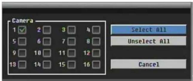
Alarm16 will be used to Trigger Alarm, Start Record, Start Playback and Arm/Disarm.
5.5.2 Event
This section covers internal system event warnings.
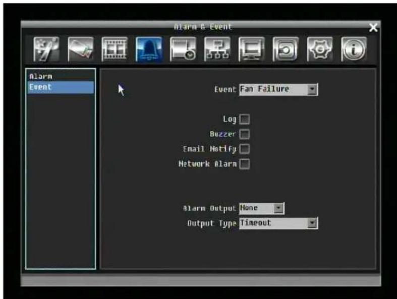
Figure 5-11 Alarm & Event Menu – Event
Event: Select from the following event types.
Fan Failure: The internal fans are equipped with rotation detection. Any fault of a fan will cause "Fan Failure" event.
HD Temperature: Hard drive is over the safety warning temperature
HD Failure: If DVR fails to detect a HDD on start up, the system will create a HD failure event.
HD Full: If the DVR is not set to Overwrite in the Record Menu, an event will be created when all HDDs are filled.
HD Off: If HDDs are switched off or are removed, the DVR will create a HD OFF event.
Power Loss: The DVR keeps a record of any time the system is powered off.
NOTES: ←hen using a contact output for this feature, make sure the control output is 5V effective.
Record Stop: If recording is stopped, the DVR will create an event.
If an output is assigned to Record Stopped, any other events assigned for that alarm output will automatically change to "None".
Network Loss: If connection to network is lost, DVR will create a Network Loss event.
NOTE: This function only checks physical connection to the network. Any network behavior that blocks connection (blocked ports, wrong IP setup, etc.) is not detected by this function.
Fan Failure:
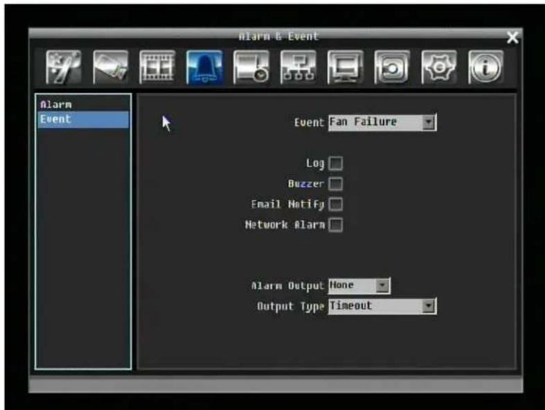
Figure 5-12 Alarm & Event Menu – Event-Fan Failure
Log: Check box to record events in the log.
Buzzer: Check box to enable buzzer when a fan fails to work.
Email Notify: Check box to enable email notification when a fan fails to work.
Network Alarm: Check box to send out a network alarm to client PC. (requires PowerCon software and setting up Alarm Server in Network Setup menu)
Alarm Output: This will transmit a signal through one of the alarm outputs. It can be set to either "NONE" (not active), "1", "2", "3", or "4".
Output Type: Output action is locked to Transparent
HD Temperature:
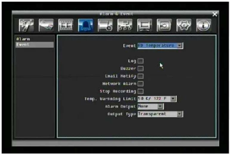
Figure 5-13 Alarm & Event Menu – Event - HD Temperature
Log: Check box to record events in the log.
Buzzer: Check box to enable buzzer when hard drive's temperature is over the "Temp. ← arning Limit".
Email Notify: Check box to enable email notification when temperature is over the "Temp. ← arning Limit".
Network Alarm: Check box to send out a network alarm to client PC. (requires PowerCon software and setting up Alarm Server in Network Setup menu)
Stop Recording: Check box to stop recording when HD's temperature is over the "Temp. ←arning Limit".
Temp. Warning Limit: Sets the trigger temperature for all other active settings in HD Temperature. Choose from 55°C /131°F\~85°C /185°F.
Alarm Output: This will transmit a signal through one of the alarm outputs. It can be set to either "NONE" (not active), "1", "2", "3", or "4".
Output Type: Output action is locked to Transparent
HD Failure:
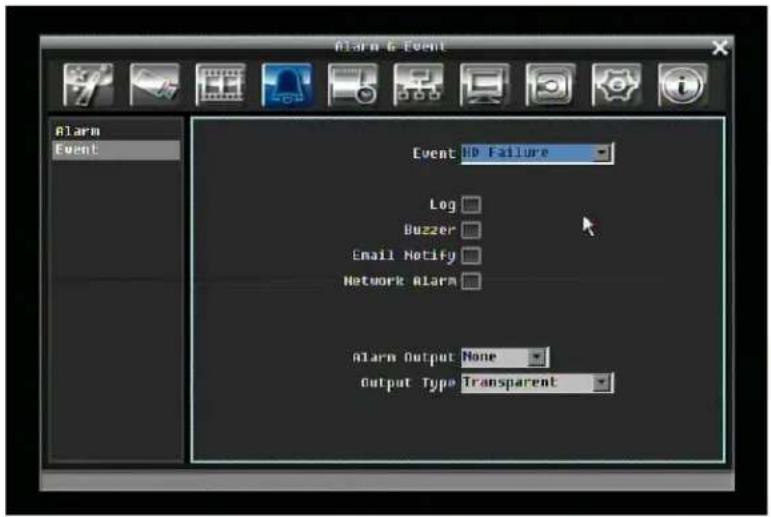
Figure 5-14 Alarm & Event Menu – Event - HD Failure
Log: Check box to record events in the log.
Buzzer: Check box to enable buzzer when no hard drive is detected.
Email Notify: Check box to enable email notification function when HD fails.
Network Alarm: Check box to send out a network alarm to client PC. (requires PowerCon software and setting up Alarm Server in Network Setup menu)
Alarm Output: This will transmit a signal through one of the alarm outputs. It can be set to either "NONE" (not active), "1", "2", "3", or "4".
Output Type: Output action is locked to Transparent
HD Full:
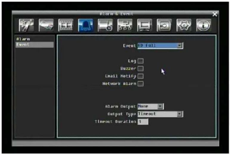
Figure 5-15 Alarm & Event Menu – Event - HD Full
Buzzer: Check box to enable buzzer when hard drive is full.
Email Notify: Check box to enable email notification when HD is full.
Network Alarm: Check box to send out a network alarm to client PC. (requires PowerCon software and setting up Alarm Server in Network Setup menu)
Alarm Output: This will transmit a signal through one of the alarm outputs. It can be set to either "NONE" (not active), "1", "2", "3", or "4".
Output Type: Output action when alarm is triggered.
Timeout: Alarm output lasts for the set time duration.
Permanent: Alarm will be continuously active until user presses "Enter" key.
Transparent: Alarm output remains active until event ends.
Trans+Timeout: Alarm output continues until event ends, then lasts for the set time duration.
Timeout Duration: The amount of time the buzzer sounds when the HD is full. Duration selectable from 1 to 150 seconds.
HD Off:
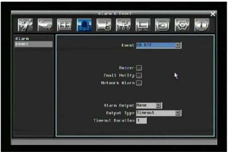
Figure 5-16 Alarm & Event Menu – Event - HD Off
Buzzer: Check box to enable buzzer when hard drive is off.
Email Notify: Check box to enable email notification when HD is off.
Network Alarm: Check box to send out a network alarm to client PC. (requires PowerCon software and setting up Alarm Server in Network Setup menu)
Alarm Output: This will transmit a signal through one of the alarm outputs. It can be set to either "NONE" (not active), "1", "2", "3", or "4".
Output Type: Output action when alarm is triggered.
Timeout: Alarm output lasts for the set time duration.
Permanent: Alarm will be continuously active until user presses "Enter" key.
Transparent: Alarm output remains active until event ends.
Trans+Timeout: Alarm output continues until event ends, then lasts for the set time duration.
Timeout Duration: The amount of time the buzzer sounds when the HD is off. Duration selectable from 1 to 150 seconds.
Power Loss:
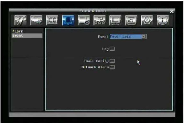
Figure 5-17 Alarm & Event Menu – Event – Power Loss
Log: LOG is permanently checked for this feature. Power Loss events are always recorded by the DVR.
Email Notify: Check box to enable email notification when HD is off.
Network Alarm: Check box to send out a network alarm to client PC. (requires PowerCon software and setting up Alarm Server in Network Setup menu)
Record Stop:

Figure 5-18 Alarm & Event Menu – Event – Record Stop
Log: Check box to record events in the log.
Buzzer: Check box to enable buzzer when DVR stops recording.
Email Notify: Check box to enable email notification when DVR stops recording.
Network Alarm: Check box to send out a network alarm to client PC. (requires PowerCon software and setting up Alarm Server in Network Setup menu)
Alarm Output: This will transmit a signal through one of the alarm outputs. It can be set to either "NONE" (not active), "1", "2", "3", or "4". (If an output is assigned to Record Stopped, any other events assigned for that alarm output will automatically change to "None")
Output Type: Output action when alarm is triggered.
Timeout: Alarm output lasts for the set time duration.
Permanent: Alarm will be continuously active until user presses "Enter" key.
Transparent: Alarm output remains active until event ends.
Trans+Timeout: Alarm output continues until event ends, then lasts for the set time duration.
Timeout Duration: The amount of time the buzzer sounds when DVR stops recording. Duration selectable from 1 to 150 seconds.
Network Loss:
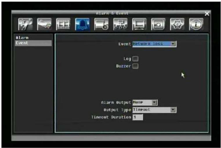
Figure 5-19 Alarm & Event Menu – Event – Network Loss
Log: Check box to record events in the log.
Buzzer: Check box to enable buzzer when network is lost.
Alarm Output: This will transmit a signal through one of the alarm outputs. It can be set to either "NONE" (not active), "1", "2", "3", or "4".
Output Type: Output action when alarm is triggered.
Timeout: Alarm output lasts for the set time duration.
Permanent: Alarm will be continuously active until user presses "Enter" key.
Transparent: Alarm output remains active until event ends.
Trans+Timeout: Alarm output continues until event ends, then lasts for the set time duration.
Timeout Duration: The amount of time the buzzer sounds when DVR stops recording. Duration selectable from 1 to 150 seconds.
5.6 SCHEDULE SETTING
Figure 5-20 is a screen shot of the SCHEDULE SETTING MENU. In this menu you can set a unique timer to start recording during a specified time period. This menu is used to configure Express Setup, Holidays and Schedule settings.
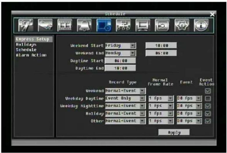
Figure 5-20 Schedule Menu-Express Setup
5.6.1 Express Setup
Weekend Starts: Select day and time when weekend starts.
Weekend End: Select day and time when weekend ends.
Daytime Starts: Select daytime starting time. (Nighttime schedule ends when Daytime begins)
Daytime End: Select daytime ending time. (Nighttime schedule begins when Daytime ends)
Record Type: Select the type of recording for each time period.
Disabled: No recording during scheduled time period
Normal+Event: Continuous and Event recording
Event Only: Event recording only
Normal Frame Rate: Continuous FPS recording rate for the scheduled time period. The maximum rate is limited to the DVR's maximum recording rate divided by the number of active cameras. Selectable frame rate includes 30fps, 15fps, 10fps, 7.5fps, 5fps, or 1fps.
Event Action: FPS recording rate for events. Selectable frame rate includes 30fps, 15fps, 10fps, 7.5fps, 5fps, or 1fps.
Event Action: Check this box to enable Buzzer, Alarm out, E-mail and Network actions when an event occurs on the selected time period.
Apply: Press Apply button bring up a confirmation window. Select "Yes" to confirm and apply express schedule settings or "No" to cancel changes.
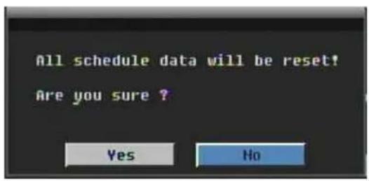
5.6.2 Holidays
In addition to setting a weekly record schedule, user can also schedule recording for specific days of the year.
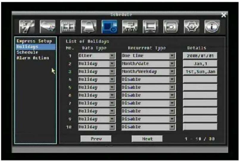
Figure 5-21 Schedule Menu-Holidays
Data Type: Select either Holiday or Others. (Holiday and Others means two different group, you can assign special days in these two group)
Recurrent Type: Choose how often each scheduled day should be recorded.
Disable: Recording is disabled.
One time: Records date only once.
Month/date: Repeats recording on the same specific date.
Month/weekday: Repeats recording on a specific day of the month/week.
Details: Specifies the date to be recorded.
Prev: Previous Page (30 Holidays Total)
Next: Next Page (30 Holidays Total)
5.6.3 Schedule
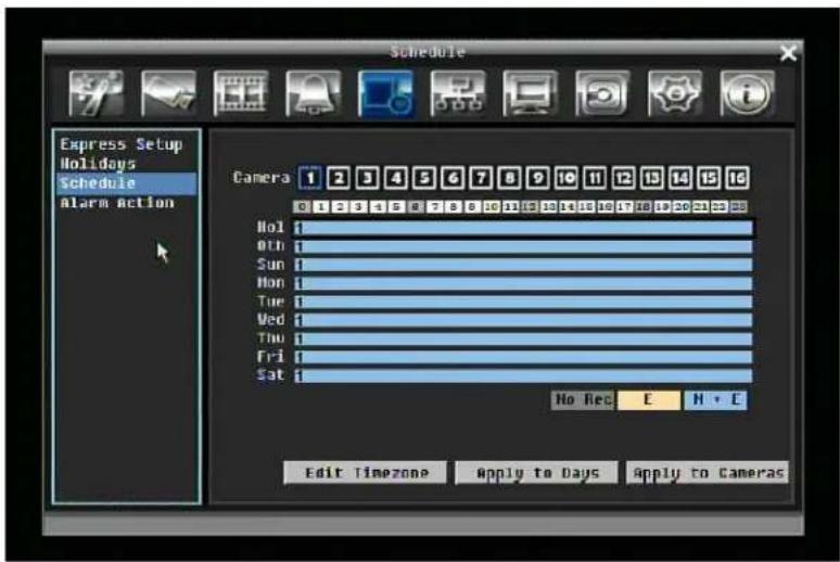
Figure 5-22 Schedule Menu-Schedule
Camera: Select a number to change the schedule for that camera. Each camera can be set on a 24 hour time block for Holiday (Hol), Other (Oth), Sunday (Sun), Monday (Mon), Tuesday (Tue), ←ednesday (←ed), Thursday (Thu), Friday (Fri), or Saturday (Sat).
Time Bar: The time bar uses three different colors to distinguish each recoding mode.
Gray (No Rec): No recording during this time block.
Orange (E): Only events are recorded during this time block.
Blue (N+E): (Default) Normal and event recording during this time block.
To Set Schedule using Mouse
-
There are 24 blocks on the time bar representing 24 hours respectively. Set a schedule start time by clicking on a desired start time block on a time bar and clicking again to confirm it. At this time, the selected block and all following blocks will turn gray, which means this gray timezone has been set to the recording mode of gray(No Rec).
-
Change the section to different mode (with different color) by clicking on the first block of each section. The color swatches from gray -> orange -> blue, every time user clicks the first block of a section.
Schedule Setting from front panel
- Enter schedule setting mode: press Enter button to enter schedule setting mode. At this time, the whole editing area at right-down side will be highlighted within a blue frame. See below image.
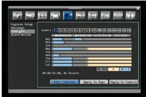
- Enter camera selection mode: turn Jog knob to switch to Camera selection mode. ←hen Camera selection mode is selected, all 16 cameras will be highlighted in a blue frame. See below image.
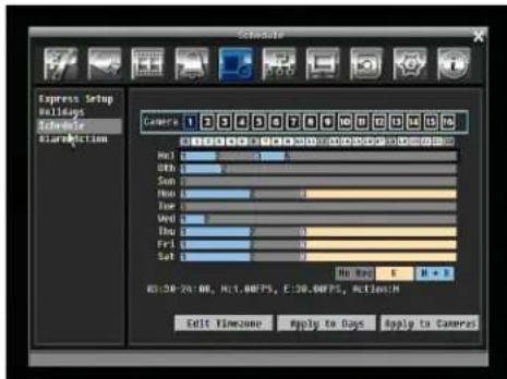
-
Selecting camera: Turn Shuttle knob to select desired camera to configure. Selected camera number will be highlighted by a blue frame. See above image.
-
Enter time bar editing mode: turn Jog knob to switch to time bar editing mode. ←hen this mode is selected, all 9 time bars will be highlighted within a blue frame.
-
Select desired time bar for setting: press Enter button, the first time bar will be selected for setting and highlighted in a red frame. See below image. Press Jog to switch to desired time bar for setting.

- Editing blocks in a time bar: when a time bar is selected (highlighted in red frame), press Enter button, then the first block of this bar will be selected (highlighted in blue frame). Turning Jog knob to switch to desired block as starting time, and press Enter button again to confirm. At this time, the current and all following blocks will turn into gray, which means this gray timezone has been set to the recording mode of gray(No Rec). User can also change the timezone to a different record mode (with different color) by following instruction in next step.
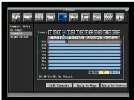
- Changing recording mode (color) of a timezone: Turn Jog knob to switch to the first block (with number on it) of a timezone. Clicking Enter button and this timezone will switch to another color, which means switching to another record mode. The color switch sequence is gray->orange->blue.
Press "Edit Timezone" button to edit the time zone.
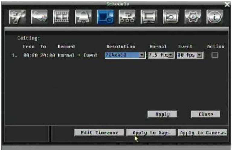
Figure 5-23 Schedule Menu-Schedule-Edit Timezone
Editing Timezone:
From: Displays schedule start time
To: Displays schedule end time
Record: Displays Record mode
Resolution: Select recording resolution.
NTSC: 704x480; 704x240; 352x240
PAL: 704x576, 704x288, 352x288
Normal: Frame rate in images per second for continuous recording. The speed is limited to the maximum recording rate of the DVR divided by the number of installed cameras.
Event Speed: Frame rate in images per second for event recording. Event record speed can be set from 1 to 30 (25 for PAL).
Action: Check this box to enable Buzzer, Alarm out, E-mail, and Network when an event occurs.
Apply to Days: This button can be used to copy schedules to other days. Select which days you wish to copy to. "Select All" selects all days, "Clear All" deselects all days. Click "OK" to copy the settings or "Cancel" to exit without copying.
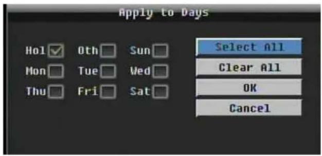
Apply to Cameras: This button can be used to copy schedules to other cameras. Select which cameras you wish to copy to. "Select All" selects all cameras, "Clear All" deselects all cameras. Click "OK" to copy the settings or "Cancel" to exit without copying.
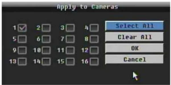
5.7 NETWORK SETTING
Figure 5-24 is a screen shot of the NETWORK SETTING MENU. This menu is for configuring the DVR for a network connection.
NOTE: Since every Network Configuration is different, please check with your Network Administrator or ISP to see if your DVR requires specific IP addresses and/or port numbers.
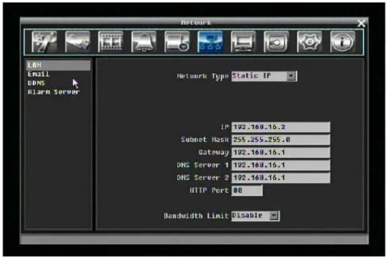
Figure 5-24 Network Menu – LAN
5.7.1 LAN
Network Type:
Static IP: User can set a fixed IP for network connection.
DHCP: DHCP server in LAN will automatically assign IP for network connection
PPPoE: For direct connection to DSL ONLY. Verify with your ISP if they use PPPoE.
IP: This field shows the DVR's current IP Address. A static IP address must be set manually. If DHCP or PPPoE is selected, this value will be assigned automatically.
Subnet Mask: This field shows the subnet mask for your network so the DVR will be recognized within the network. If DHCP or PPPoE is selected, this value will be assigned automatically.
Gateway: This field shows the gateway for your network so the DVR will be recognized within the network. If DHCP or PPPoE is selected, this value will be assigned automatically.
DNS Server 1: This field shows the primary DNS server for your network. If DHCP is selected and an internet connection is available, this value will be assigned automatically. This field must have a valid DNS address in order to use the DDNS feature (see 5.7.3 for more detail).
DNS Server 2: This field shows the secondary DNS server for your network.
HTTP Port: Port number for HTTP/←EB communication.
Bandwidth Limit: Allows user to limit the bandwidth used by the DVR.
5.7.2 EMAIL
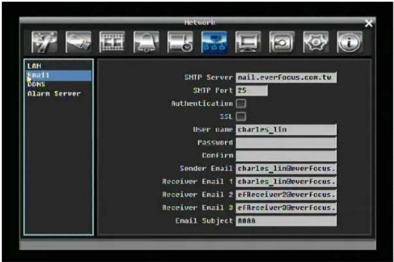
Figure 5-25 Network Menu – Email
SMTP Server: Assign the SMTP (e-mail) server's name.
NOTE: For more reliable email service, use the server's IP address.
SMTP Port: Assign the port number used by the SMTP server.
Authentication: Check this box if the SMTP server requires authentication (user name / password).
SSL: Check the box if mail server needs to be encrypted by SSL.
User name: Input the login user name if the SMTP server requires authentication.
Password: Input the password if the SMTP server requires authentication.
Sender Email: Input the e-mail address of the sender (DVR).
Receiver Email 1: Input the first e-mail address that event messages are sent to.
Receiver Email 2: Input the second e-mail address that event messages are sent to.
Receiver Email 3: Input the third e-mail address that event messages are sent to.
Email Subject: Input email subject.
5.7.3 DDNS
DDNS Server: Select either "EverfocusDDNS" or "www.dyndns.org" as the DDNS provider. If DDNS will not be used, simply select "Disable".
EverfocusDDNS
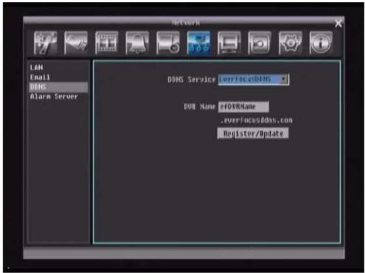
Figure 5-26 EverfocusDDNS
DVR Name: Input the desired name for the DVR
Register/Update: Click the button to submit and register the name to the Everfocus server.
www.dyndns.org
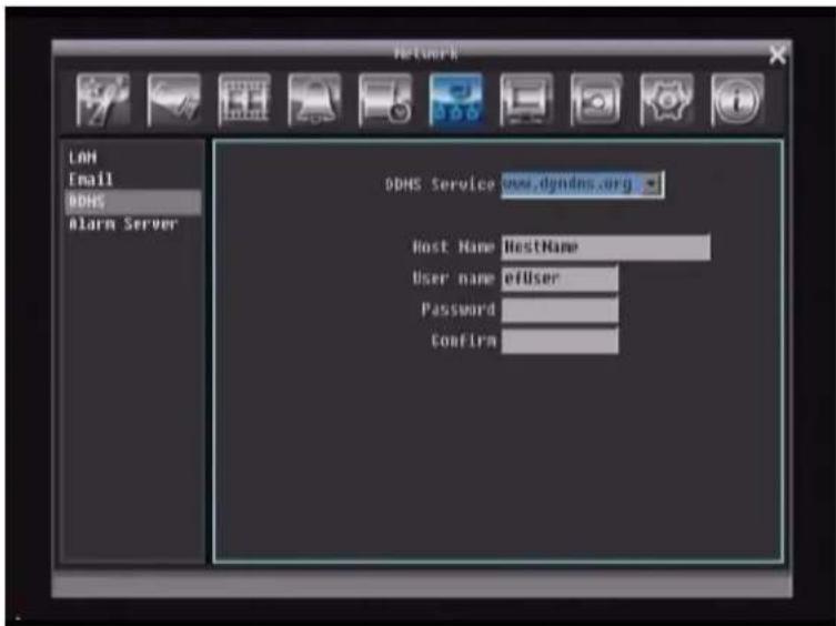
Figure 5-27 www.dyndns.org
Host name: Host name created through the dyndns account.
User name: User name of the dyndns account.
Password: Password of the dyndns account.
Confirm: Re-enter password.
Note: For more details on DDNS setup, please see "Chapter 8 - Everfocus DDNS Setup".
5.7.4 Alarm Server
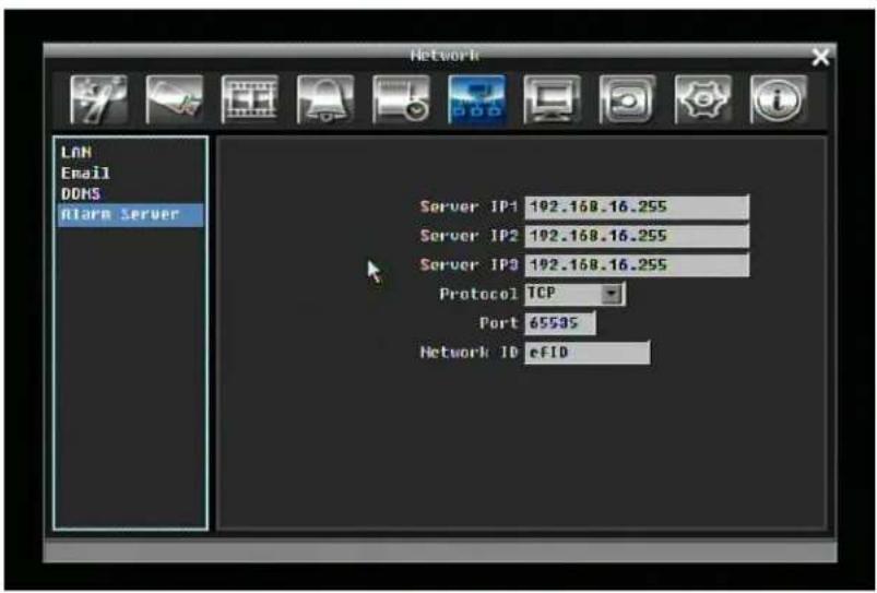
Figure 5-28 Network Menu – Alarm Server
Server IP1\~3: IP address of client PC with installed PowerCon Software. The network alarm can be transmitted to up to 3 addresses.
Protocol: Select the protocol type for alarm transmission:
UDP: User Datagram Protocol
TCP: Transmission Control Protocol
Port: Select the transmission port for network alarm messages
Network ID: The network ID is an identifier for the alarm transmitter.
5.8 DISPLAY SETTING
Figure 5-29 is a screen shot of the DISPLAY SETTING MENU. This menu will walk you through Monitor On-Screen Display (OSD) and Sequential setup.
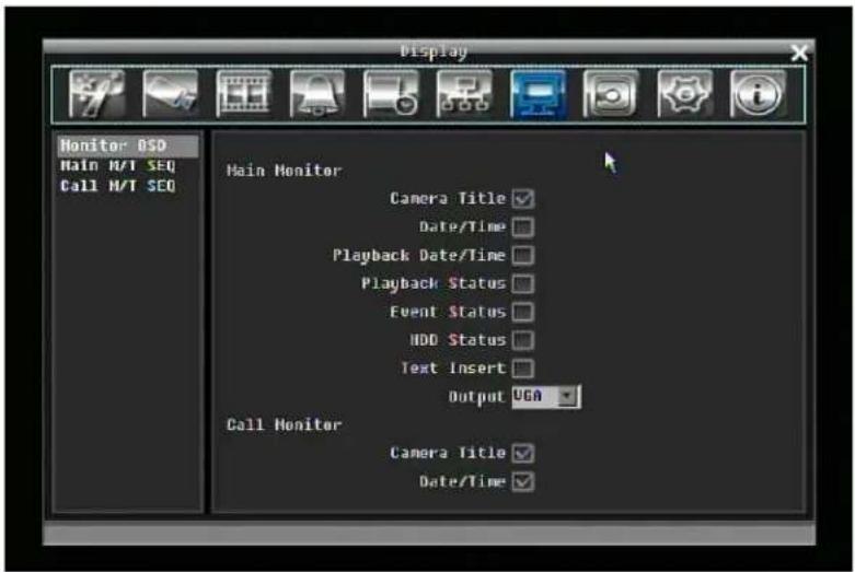
Figure 5-29 Display Menu – Monitor OSD
5.8.1 Monitor OSD
These are the display options for the Main Monitor.
Main Monitor
Camera Title: Check the box to display camera titles.
Date/Time: Check the box to display current date/time.
Playback Date/Time: Check the box to display playback date/time.
Playback Status: Check the box to display playback status.
Event Status: Check the box to display event status.
HDD Status: Check the box to display hard drive status.
Text Insert: Check the box to display data transmitted from external RS232 device.
Main Monitor Output: This system supports both VGA and BNC monitor displays at the same time but only one of them can have optimized display quality. Use this feature to select which output is optimized.
Call Monitor
Camera Title: Check the box to display camera titles.
Date/Time: Check the box to display current date/time.
5.8.2 Main M/T SEQ
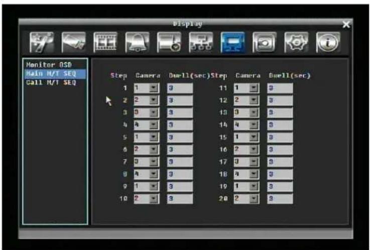
Figure 5-30 Display Menu – Main M/T SEQ
Step: Sequence order. Cannot be changed.
Camera: Select which camera appears on the current step.
Dwell (sec): Set the dwell time for each step. Sequence dwell time can be set from 0 to 99 seconds.
5.8.3 Call M/T SEQ
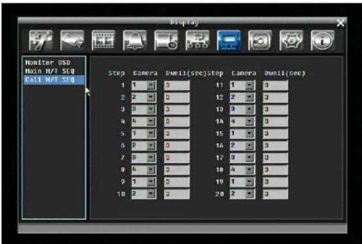
Figure 5-31 Display Menu – Call M/T SEQ
Step: Sequence order. Cannot be changed.
Camera: Select which camera appears on the current step.
Dwell (sec): Set the dwell time for each step. Sequence dwell time can be set from 0 to 99 seconds.
5.9 DISK SETTING
Figure 5-32 is a screen shot of the DISK SETTING MENU. This menu is used to review and manage the DVR's hard drive settings.
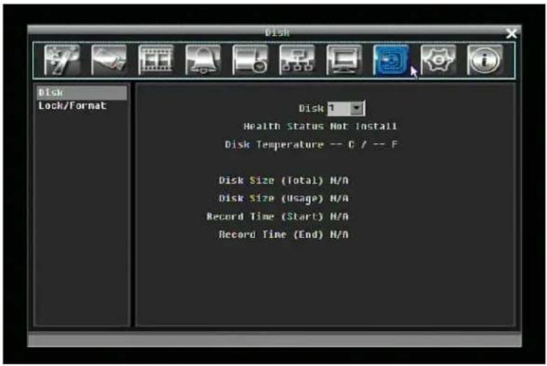
Figure 5-32 Disk Menu
5.9.1 Disk
Disk: Select the disk number.
Health Status: Displays current status of the selected disk.
Disk Temperature: Displays current disk temperature.
Disk Size/Total: Shows total disk size.
Disk Size/Usage: Shows percentage of used disk space. If DVR is set to automatically overwrite the disk, this option will show "Overwrite mode currently".
Record Time (Start): Shows earliest recorded time on the hard drive.
Record Time (End): Shows latest or most current recorded time on the hard drive.
5.9.2 Lock/Format
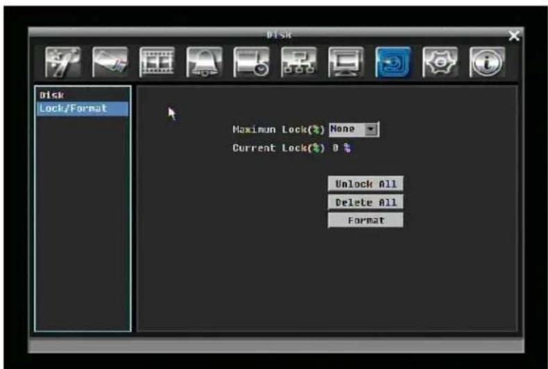
Figure 5-33 Lock/Format Menu
Maximum Lock (%): User can set the maximum lock percentage of the HDD volume. After setting lock percentage, it can be enabled/disabled in three places
- "Camera > Basic Setting > Motion > Auto Lock"
- "Alarm & Event > Alarm > Auto Lock".
- Lock or unlock the file manually in search result list
Current Lock (%): Here displays the current lock percentage of HDD volume. If locked data has reach the maximum lock percentage, it will stop lock new data.
Unlock All: Click this button to unlock the locked part of HDD.
Delete All: Click this button to delete all the unlocked data in HDD.
Format: Click this button to format the whole HDD.
Note: the following rules apply to Hot Swappable model only
-
If user takes out the HDD and put it back (with the same HDD) to the same DVR. It will be fine.
-
If user takes out the HDD-A of Paragon-A, then put it into another Paragon-B which already has a HDD-B. The data of HDD-A will be cleaned in Paragon-B. If user hopes to keep the data of HDD-A, user has to use the HDD Reader to backup it.
Before formatting the HDD, a warning message will pop up: "Hard Disk drive will be formatted! Continue ? > OKAY / CANCEL (in case of CANCEL, DVR will ignore the disk, no data will be written to this disk).
-
If there is only one HDD in Paragon, then the DVR will consider this HDD as its own, no matter which DVR this HDD is actually coming from.
-
If user inserts the HDD-B and HDD-C into Paragon-A which has no HDD inside, a warning message will pop up “Found HDD(s) recorded from other DVR(s). Do you want to format it to record? Yes/No” In case of “No”, stop recording is executed, no response to any record request including manual, event and schedule recording. Only HDD-B (the one in first HD position) will be readable and playback-able; whereas HDD-C & HDD-A will be ignored. If “Yes”, HDD-B, HDD-C will be formatted.
5.10 SYSTEM SETTING
Figure 5-34 is a screen shot of the SYSTEM SETTING MENU. This menu is for setting up the system configurations of the DVR.
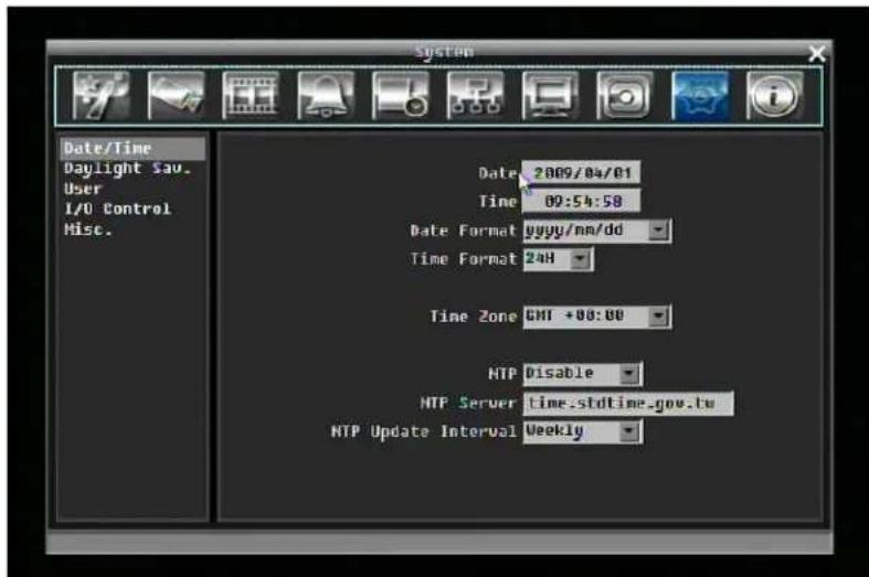
Figure 5-34 System Menu – Date/Time
5.10.1 Date/Time
Date: Set current Date.
Time: Set current Time.
Date Format: Choose date format from yyyy/mm/dd, dd/mm/yyyy, and mm/dd/yyyy.
Time Format: Change time format between 12H and 24H mode.
Time Zone: Set the time zone that the DVR adjusts to when updating from the time server.
NTP: Select "Enable" or "Disable" NTP time synchronization.
NTP Server: Displays the time server address that the uses for time synchronize. To find a compatible NTP address, please follow these steps:
a) Go to a PC that is connected to the internet.
b) Click on "START" -> "RUN" -> type "command" and press "OK".
c) In the DOS Prompt, type "ping pool.ntp.org" to find out the IP address of an NTP Server.
NTP Update Interval: The frequency that the system automatically updates the time. Select Daily, ←eekly or Monthly.
5.10.2 Daylight Saving
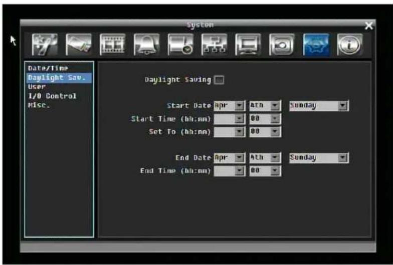
Figure 5-35 System Menu – Daylight Saving
Daylight Saving: Check the box to enable daylight saving time.
Start Date: Set the start date of daylight saving time.
Start Time (hh:mm): Set the time when daylight saving time begins.
Set To (hh:mm): This is what the time will change to when daylight saving begins. For most regions, this will be one hour ahead of the "Start Time".
End Date: Set the end date of daylight saving time.
End Time (hh:mm): Set the time when daylight saving time ends.
5.10.3 User
User Menu is where you can add or delete different users on the system as well as set administrator rights.
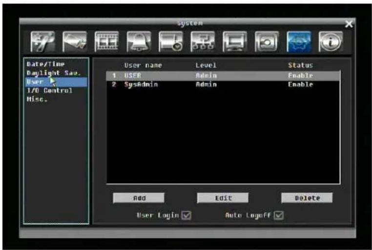
Figure 5-36 System Menu – User
Add
Click "Add" button to add a new user. Set the name (case-sensitive), password, and access level. Press "Add" button to confirm a new user or "Cancel" to exit without making changes.
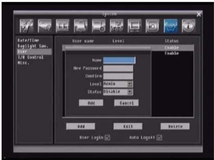
Figure 5-37 System Menu – User - Add
Edit
Click "Edit" button to make changes to an existing user account. Press "Save" button to save changes or "Cancel" to exit without making changes.
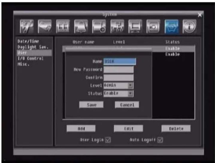
Figure 5-38 System Menu – User - Edit
User Login: Check this box to activate user login. ←hen this is disabled, no username or password is required to access the system, and all users operate with ADMIN rights.
Auto Logoff: Check this box to automatically logoff the current user after 3 minutes of inactivity.
5.10.4 I/O Control
Figure 5-39 is a screen shot of the I/O Control Setting Menu. This menu is used to define the settings for controlling the DVR through RS232 or RS485.
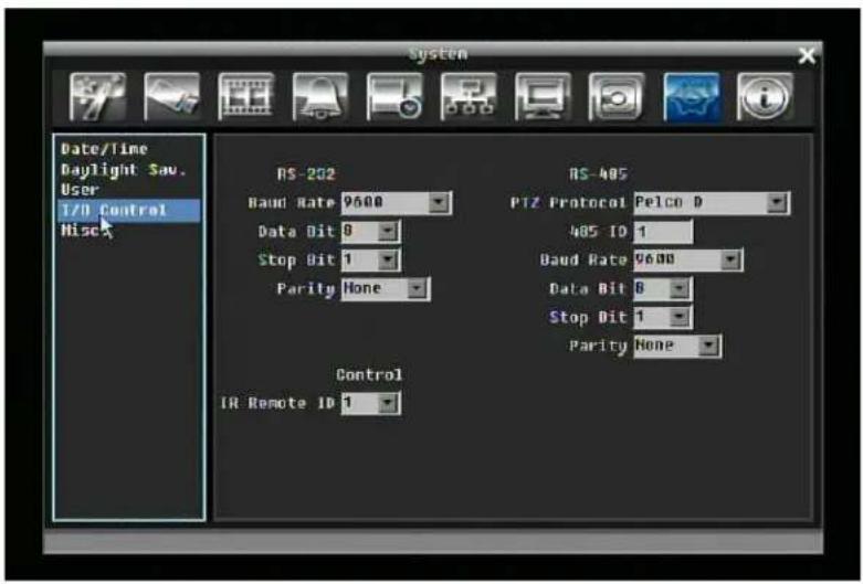
Figure 5-39 System Menu - I/O Control
RS232
Baud Rate: The speed used to transmit instruction or information through the RS232 port on the DVR. Choose from the following speeds: 1200, 2400, 4800, 9600, 19200, 38400, 57600, or 115200 BPS.
Data Bit: The data bit used for transferring. This can be set to 8 or 7.
Stop Bit: This field is to set the stop bit for the RS232 connection. This can be set to 1 or 2.
Parity: This selects the transmission level of the connection. Choose either None, Odd, or Even.
RS485
PTZ Protocol: Select PTZ protocol Choose from the following protocols: Transparent, Pelco D, Pelco P, Everfocus, or Samsung. (NOTE: all cameras must be on the same protocol)
485 ID: If more than one DVR is used through the RS485 connection, each one must be assigned a unique ID number between 0 and 127.
Baud Rate: The speed used to transmit instruction or information through the RS485 port on the DVR. Choose from the following speeds: 1200, 2400, 4800, 9600, 19200, 38400, 57600, 115200 BPS.
Data Bit: The data bit used for transferring. This can be set to 8 or 7.
Stop Bit: This field is to set the stop bit for the RS485 connection. This can be set to 1 or 2.
Parity: This selects the transmission level of the connection. Choose either None, Odd, or Even.
Control
IR Remote ID: ID used by the remote control. This can be set from 1 to 4.
5.10.5 Misc.
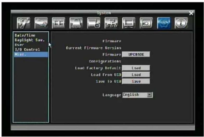
Figure 5-40 System Menu – Firmware & Misc.
Firmware
Current Firmware Version: Displays the current version.
Firmware Upgrade: Press "Upgrade" to upgrade the firmware.
NOTE: To perform a Firmware Upgrade, you will need to connect a USB flash device with the latest version of the firmware. Do not disconnect USB device or turn off the power of the unit during the upgrade; this can cause the system to crash.
Configurations
Load Factory Default: Click "Load" to restore all menu settings to the default values. User Account, Network Setting, and Time are not affected.
Load From USB: Click "Load" to upload saved DVR configuration settings from a USB flash device.
Save To USB: Click "Save" to save the current DVR configuration settings to a USB flash device.
Language: Choose which language the DVR uses. The available languages may vary based on region.
5.11 INFORMATION SETTING
Figure 5-41 is a screen shot of the INFORMATION SETTING MENU. This menu displays important system information.
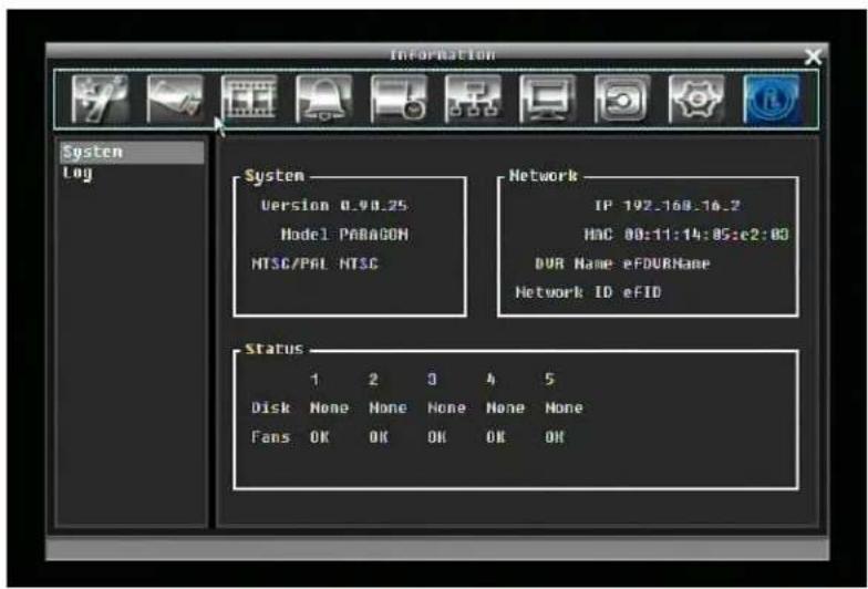
Figure 5-41 Information Menu – System
5.11.1 System
System
Version: Displays firmware version number.
Model: Displays DVR model number.
NTSC/PAL: Displays current video format.
Network
IP: Displays the DVR's current IP Address.
MAC: Unique address of the DVR's internal network card. This option cannot be changed.
DVR Name: Displays DVR name
Network ID: The ID number for the alarm network.
Status
Disk: Displays disk temperature.
Figure 5-42 Information Menu – Log
Log Type:
Event: to see log sorted by event.
User: to see log sorted by user.
Operation: to see log sorted by operation.
View Log: Press "View Log" button to view the log. See Figure 5-43 for more detail.
Clear Log: Press "Clear Log" button to clear the log.
Export Log to USB: Export log data to USB.
![Information ID Date Status 1 [2009/04/08 11:06:54] Motion Detection occurred on camera2 2 [2009/04/08 11:06:54] Motion Detection occurred on camera4 3 [2009/04/08 11:06:54] Motion Detection occurred on camera3 4 [2009/04/08 11:06:54] Motion Detection occurred on camera1 5 [2009/04/08 11:07:03] Motion Detection occurred on camera2 6 [2009/04/08 11:07:03] Motion Detection occurred on camera1 7 [2009/04/08 11:07:03] Motion Detection occurred on camera4 8 [2009/04/08 11:07:03] Motion Detection occurred on camera3 9 [2009/04/08 11:07:12] Motion Detection occurred on camera3 10 [2009/04/08 11:08:08] Motion Detection occurred on camera1 11 [2009/04/08 11:08:08] Motion Detection occurred on camera4 12 [2009/04/08 11:08:08] Motion Detection occurred on camera3 13 [2009/04/08 11:08:08] Motion Detection occurred on camera2 14 [2009/04/08 11:08:20] Motion Detection occurred on camera2 15 [2009/04/08 11:08:20] Motion Detection occurred on camera1 Prev Page 1/30 Next Page Close](/content/2026/05/959603/images/940cf25574ef50619a4218c22459e1c1f52a7333be711b23b6e7cb7be9a8dfa6.jpg)
Figure 5-43 Log List
Prev Page: Go to the previous page of log.
Next Page: Go to the next page of log.
Close: Close the window
6 Networking Overview
This chapter will give you a basic instruction on how to set up the DVR for network connection. It is highly recommended that you have a working knowledge of what a network is and how it works. This will be helpful in completing the networking process.
6.1 Introduction to TCP/IP
TCP/IP is the group of protocols used by the Internet and most Local Area Networks (LANs) throughout the world. In TCP/IP, every computer or other communications device that is connected to the network has a unique IP address. By doing this you are giving your device a unique address similar to the address of your house. An IP address is composed of four octets (numbers in the range of 0 to 255) separated by decimal points. The IP address is used to uniquely identify a host or computer on the LAN. For example, one computer on a network could have an IP address of 192.168.1.127.
You should never give two or more devices the same exact IP address, but the first three octets of an IP address should be the same for all computers in the local area network. For example, if a total of 253 computers exist in a single LAN, the IP addresses could be assigned starting with 192.168.1.x, where x represents a number in the range of 2 to 254.
6.2 Subnet Masks
Each host in a LAN has a subnet mask. The subnet mask is a set of octets that is used to determine which LAN or class it belongs to. The number 255 is usually used to represent the network address portion of the IP address and a zero is placed at the end to identify the host portion of the address. Basically the subnet mask can be compared to the city you live in for your home address, but in this case you are stating the network you belong too.
6.3 Gateway Address
Each host in a LAN has a gateway. A gateway address is composed of four octets separated by decimal points. The gateway address is used to uniquely identify the main host or computer on the LAN that assigns the IP addresses to your network (usually a router). This is comparable to the zip code of your address.
6.4 Virtual Ports
A port number represents a "channel" or entryway for network communications. Port numbers allow different applications on the same computer to utilize network resources without interfering with each other. Port numbers most commonly appear in network programming, particularly socket programming. Sometimes, though, port numbers are made visible to the casual user. For example, some websites on the Internet use a URL like the following:
http://www.fakeaddress.com:8100/
In this example, the number 8100 refers to the port number used by the browser to connect to the web server. The standard port number used by web sites is 80, so this number does not need to be included with the URL (although it can be). In IP networking, port numbers can theoretically range from 0 to 65535. Most popular network applications, though, use port numbers at the lower end of the range (such as 80 for HTTP). Ports are similar to doors and windows of your house, with port 80 acting as the front door. If these are not open you could not enter the house. This is the same case with ports on a network. If the ports for a specific IP address are not open then you could not gain access to that IP address.
Note: The term port also refers to several other aspects of network technology. A port can refer to Ethernet connection points, such as those on a hub, switch, or router. The term port is also used to refer to a physical connection point for peripheral devices such as serial, parallel, and USB ports.
6.5 Pre-Installation
Before beginning the installation, please answer the following questions:
Do you have Hi-speed Internet? ____
There are many types of high speed Internet available. The most common ones are T1, Cable, and DSL (in order of speed). The DVR is not compatible with a dial-up connection.
- Note: EverFocus suggests having a minimum upload speed of 256KBps. This can be addressed by your Internet Service Provider.
←hat type of modem/router do you have?
Modem/router model name/#
The modem/router was either installed by your Internet service provider or purchased by you to establish a connection to the Internet. A router assigns different internal IP addresses to local computers; this allows multiple computers to access the Internet through the same external IP address.
Do you have a static IP address?
A Static IP address means you use the same IP address every time you connect to the Internet. ←ith a static IP address, other Internet users always know the address of your location and can easily connect with it. This makes it much simpler to host a website, email server, or other type of server connection. Everfocus suggests using a static IP address. If this is not available, you will need to use a dynamic IP address. This is explained below.
Do you have a dynamic IP address?
A Dynamic IP address means your IP address changes each time you connect to the Internet. ←e recommend asking your Internet service provider for a Static IP address. If this is not a possibility, you may use the DDNS feature of the DVR. DDNS stands for Dynamic Domain Name Server, a service that provides a central database where IP information can be stored and retrieved. It allows those using a dynamic IP address to be registered centrally so users can connect to it by name. See Chapter 8 for details on using EverFocus DDNS.
←hat type of DVR are you installing?
Everfocus EDR series: EDR 410, 810, 920, 1620, 1640, or 1680
Everfocus EDVR series: EDVR 4D1, 9D1, 16D1, 16D3
Everfocus ECOR series: ECOR 4, 8
6.6 What is your Network Setup?
Everfocus DVR's can operate using one of three types of networking connections.
- Simple One to One Connection: A simple one to one connection is the simplest type of network connection. It uses a cross-over cable to make a direct connection from one computer to another (or in this case a computer to a DVR).
- Direct High Speed Modem Connection: A direct modem connection uses a standard network cable to connect the modem directly to a computer (or in this case a modem to the DVR). This type of connection only covers single-port modems. For a combination modem/router, use the setup described below.
- Router or LAN Connection – A local area network connection requires either a router or a pre-existing LAN connection. This is the most common type of connection. A router allows multiple computers and DVR's to access each other as well as the Internet. It assigns different internal IP addresses to the computers.
6.7 Simple One to One Connection
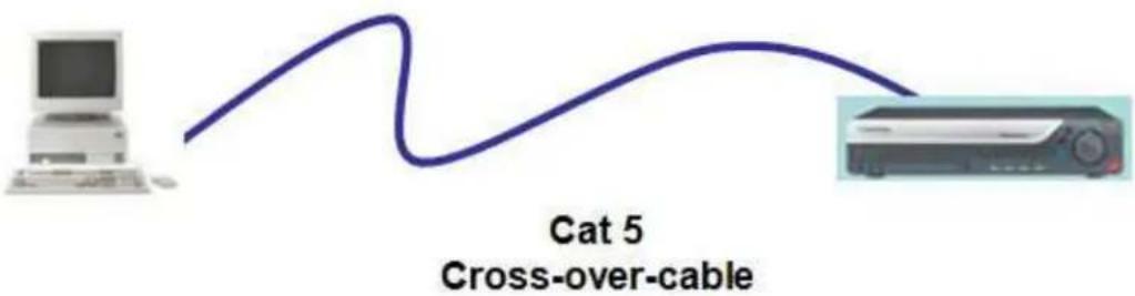
Crossover Ethernet Cable Pin outs:
The Figure below shows the pin configurations for a cross-over cable.
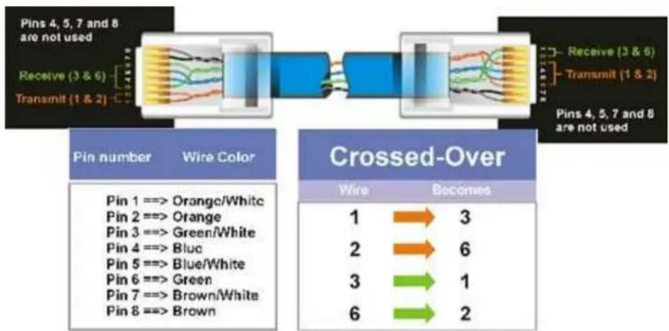
flowchart
graph LR
    A["Pins 4, 5, 7 and 8 are not used"] --> B["Receive (3 & 6)"]
    B --> C["Transmit (1 & 2)"]
    C --> D["Receive (3 & 6)"]
    D --> E["Pins 4, 5, 7 and 8 are not used"]

    subgraph Pin Number
        F["Pin 1 ==> Orange/White"]
        G["Pin 2 ==> Orange"]
        H["Pin 3 ==> Green/White"]
        I["Pin 4 ==> Blue"]
        J["Pin 5 ==> Blue/White"]
        K["Pin 6 ==> Green"]
        L["Pin 7 ==> Brown/White"]
        M["Pin 8 ==> Brown"]
    end

    subgraph Crossed-Over
        N["1"] --> O["3"]
        P["2"] --> Q["6"]
        R["3"] --> S["1"]
        T["6"] --> U["2"]
    end
Connection Procedure:
The First step is to purchase or make a cross-over cable. ←e recommend purchasing one if you have never made a cross-over cable. Please remember you can not use a straight through network cable for this application
Once you have a cross-over cable plug one end into the LAN port on the back of the DVR and the other into the network card on the back of the computer.
Log into the EverFocus DVR menu and go to the Network Setting Menu.
You must use the Static IP option for this type of connection.
Assign an IP of 192.168.001.003, a Subnet Mask of 255.255.255.000, and a Gateway of 192.168.001.001. You can ignore DNS Server.
The next step is to set the computer's network settings to match those of the DVR. You will need Administrator privileges on your ←indows machine to do this.
To assign a fixed IP address in ←indows 2000/→P.
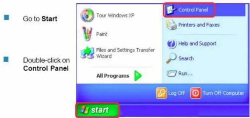
Double-click on Network Connections
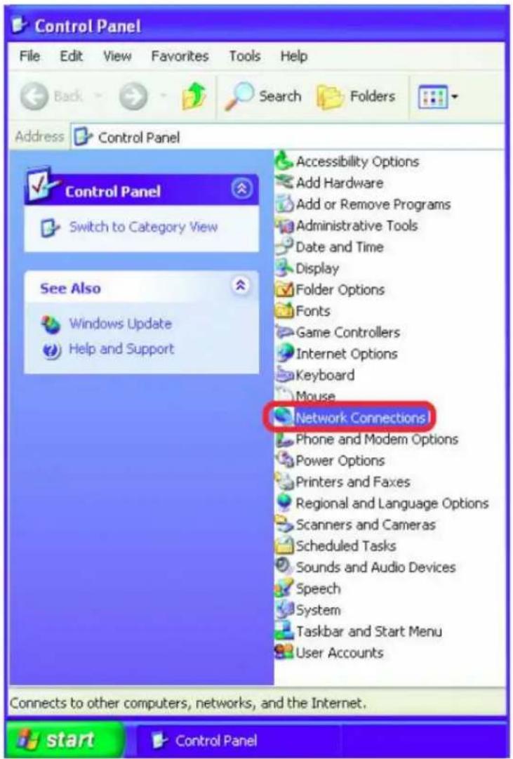
Right-click on Local Area Connections
Double-click on Properties
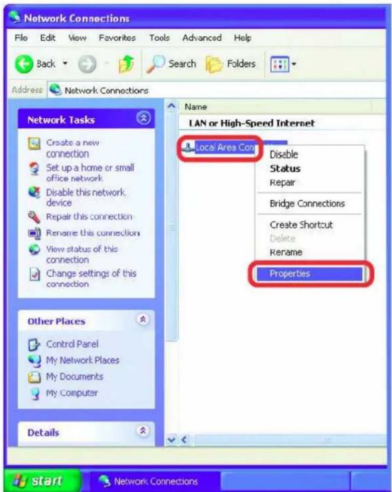
Click on Internet Protocol (TCP/IP)
Click Properties
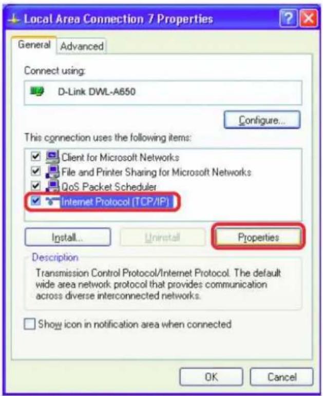
Click on the option that says "Use the following IP address"
Assign an IP address of 192.168.1.2, a Subnet Mask of 255.255.255.0, and a Default Gateway of 192.168.1.1, then click OK.
▶ Restart both the computer and the DVR.
To access the DVR from the computer, simply open Internet Explorer and in the address bar type: http://192.168.1.3
6.8 Direct High Speed Modem Connection
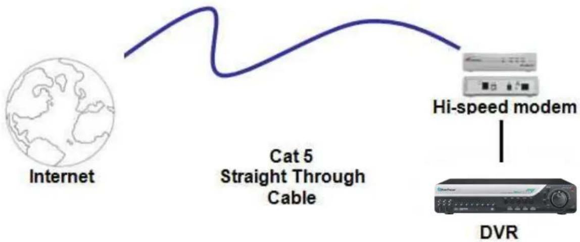
flowchart
graph LR
    A["Internet"] --> B["Cat 5 Straight Through Cable"]
    B --> C["Hi-speed modem"]
    C --> D["DVR"]
Straight Through Ethernet Cable Pin outs:
The Figure below shows the pin configurations for a straight cable.
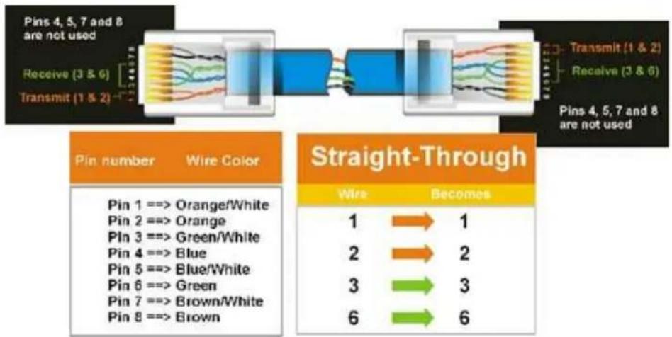
flowchart
graph LR
    A["Pin 4, 5, 7 and 8 are not used"] --> B["Receive (3 & 6)"]
    B --> C["Transmit (1 & 2)"]
    C --> D["Transmit (1 & 2)"]
    D --> E["Receive (3 & 6)"]
    E --> F["Pins 4, 5, 7 and 8 are not used"]

    G["Pin number"] --> H["Wire Color"]
    H --> I["Pin 1 ==> Orange/White"]
    H --> J["Pin 2 ==> Orange"]
    H --> K["Pin 3 ==> Green/White"]
    H --> L["Pin 4 ==> Blue"]
    H --> M["Pin 5 ==> Blue/White"]
    H --> N["Pin 6 ==> Green"]
    H --> O["Pin 7 ==> Brown/White"]
    H --> P["Pin 8 ==> Brown"]

    Q["Straight-Through"] --> R["Wire"] --> S["Becomes"]
    S --> T["1"] --> U["→"] --> V["1"]
    S --> W["2"] --> X["→"] --> Y["2"]
    S --> Z["3"] --> AA["→"] --> AB["3"]
    S --> AC["6"] --> AD["→"] --> AE["6"]
Connection Procedure:
The first step is to purchase or make a straight through cable. ←e recommend purchasing one if you have never made a straight through cable. Please remember you can not use a cross-over network cable for this application
Once you have a straight through cable plug one end into the LAN port on the back of the recorder and the other into the high speed modem.
Log into the EverFocus DVR menu and go to the Network Setting Menu.
Input the Static IP address, the Subnet Mask, and the Gateway that you obtained from the internet service provider.
- Note: If you have a dynamic IP address, you can set the DVR to DHCP to automatically detect the network settings settings. Therefore, it can use a dynamic IP address.
- Exit from the DVR's Menu to save the settings.
To access the DVR from a computer, open Internet Explorer and in the address bar type: http:// (IP address given by your internet service provider)
- Note: When using this type of connection, only one device can be connected to the modem at a time. You will need to use a computer at a different location to test the connection.
6.9 Router or LAN Connection
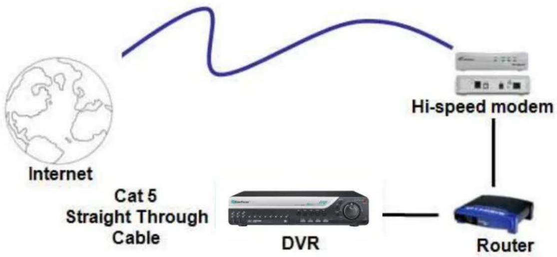
flowchart
graph LR
    A["Internet"] -->|Cat 5 Straight Through Cable| B["DVR"]
    B --> C["Hi-speed modem"]
    C --> D["Router"]
Straight Through Ethernet Cable Pin outs:
The Figure below shows the pin configurations for a straight cable.
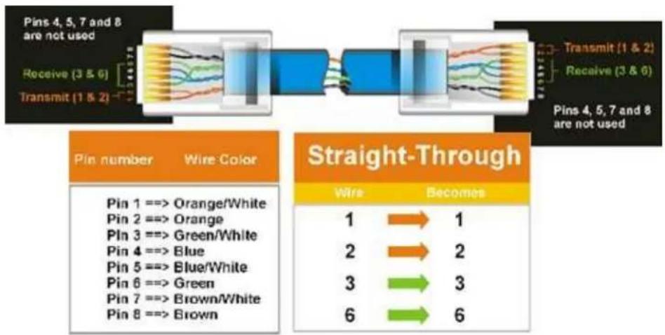
flowchart
graph LR
    A["Pin 4, 5, 7 and 8 are not used"] --> B["Receive (3 & 6)"]
    B --> C["Transmit (1 & 2)"]
    C --> D["Transmit (1 & 2)"]
    D --> E["Receive (3 & 6)"]
    E --> F["Pins 4, 5, 7 and 8 are not used"]

    G["Pin number Wire Color"] --> H["Pin 1 ==> Orange/White"]
    G --> I["Pin 2 ==> Orange"]
    G --> J["Pin 3 ==> Green/White"]
    G --> K["Pin 4 ==> Blue"]
    G --> L["Pin 5 ==> Blue/White"]
    G --> M["Pin 6 ==> Green"]
    G --> N["Pin 7 ==> Brown/White"]
    G --> O["Pin 8 ==> Brown"]

    P["Straight-Through"] --> Q["Wire: 1 → 2 → 3 → 6"]
    Q --> R["Becomes: 1 → 2 → 3 → 6"]
Connection Procedure:
The First step is to purchase or make a straight through cable. ←e recommend purchasing one if you have never made a straight through cable. Please remember you can not use a cross-over network cable for this application
Once you have a straight through cable plug one end into the LAN port on the back of the recorder and the other into the router.
Log into the EverFocus DVR menu and go to the Network Setting Menu.
To let the router automatically assign an address:
- Set the Network Type to DHCP. Make sure to write down the IP address and the Gateway.
- Exit from the Menu to save settings.
To manually assign an address:
- Go to a computer connected on the same network as the DVR.
- Click on the Start button and choose Run.
○ If using ←indows Vista, choose Search instead.
- Type "command" and click on OK.
- In Vista, you will need to double-click on the "Command Prompt" file to open it..
- In the DOS prompt, type "ipconfig" and press Enter.
■ The network information will be displayed on a screen similar to the one below.
○ In ←indows Vista, look for the information that says "IP v4".
![Command Prompt Microsoft Windows XP [Version 5.1.2600] (C) Copyright 1985-2001 Microsoft Corp. C:\Documents and Settings\Steven>ipconfig Windows IP Configuration Ethernet adapter Local Area Connection: Connection-specific DNS Suffix . : IP Address. . . . . . . . . . . . . : 192.168.0.80 Subnet Mask . . . . . . . . . . . . : 255.255.255.0 Default Gateway . . . . . . . . . . : 192.168.0.1 C:\Documents and Settings\Steven>](/content/2026/05/959603/images/a970342805005e226bc47dba353ffcc3e4657cb18b0f6a4476e0a85f9c0ed93c.jpg)
Take the values for Subnet Mask and Default Gateway and input them into the DVR; these values should be exactly the same in both devices. However, you should change the last
number of the IP address. For example, if the IP address of the computer is 192.168.2.101, the DVR's IP address should be 192.168.002.050.
To access the DVR from a computer simply open Internet Explorer and in the address bar type: http:// (IP address of the DVR)
- Note: The DVR's IP address will only work at the location of the DVR. To connect from a different location over the Internet, see below.
To set DVR for Internet Connection through router
The next step is to open ports within your router. Log into the router using a PC and open the following ports.
- Ports to open: 80, 1600
If your Internet service provider blocks port 80, you can change it to a different port in the DVR's Network Menu Setup.
If you are using a Linksys or D-Link router, see Chapter 9 for basic support on setting up ports. For any other router, you will need to contact the manufacturer for support.
To access the DVR from a computer simply open Internet Explorer and in the address bar type: http:// (the IP address given by your internet service provider)
- Note: If you changed to a different port other than 80, you will need to include this at the end of the IP address Example: http://70.20.70.20:8100
If you have a Dynamic IP address and have opened the ports, go to the next chapter to setup DDNS.
7 REMOTE OPERATION FROM BROWSER
7.1 CONNECTING TO DVR
To access the DVR from a computer, open an Internet Explorer window and in the address bar type:
Local connection: http:// (IP address from the DVR's Network Menu)
Internet connection: http:// (IP address given by your Internet Service Provider)
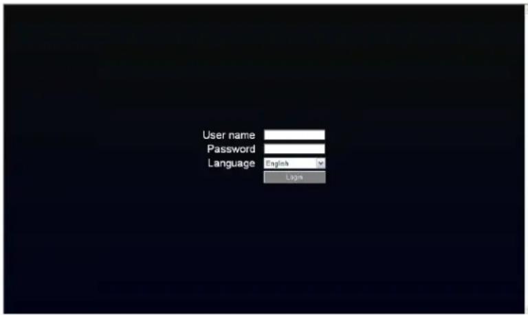
The login page will appear on the screen similar to the one shown above.
➢ Enter a user name and password to access the recorder. These can be changed in the System section of the Main Menu.
The default user name is "admin". The default password is "11111111".
Click on the Login button and you will log in to the recorder's Network Viewer.
7.2 BROWSER SECURITY SETTING
7.2.1 Installing ActiveX controls
←hen you first connect to the DVR's IP address, you should see a screen like the one below. If you do not see a yellow bar like the one the arrow is pointing at, your security settings may be too high. If so, go to "Section 7.2.2 - Enabling Active→ Controls."
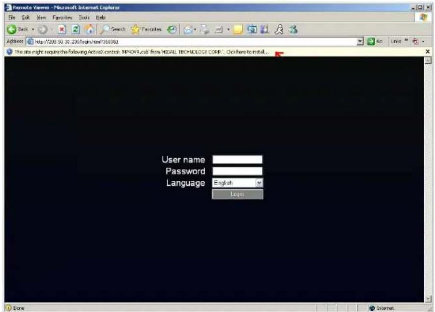
Right click on the yellow bar and select "Install Active→Control..."
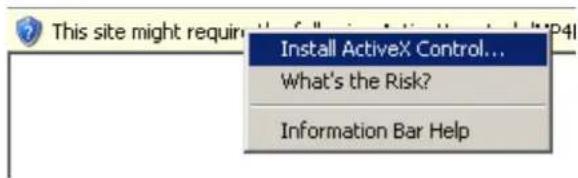
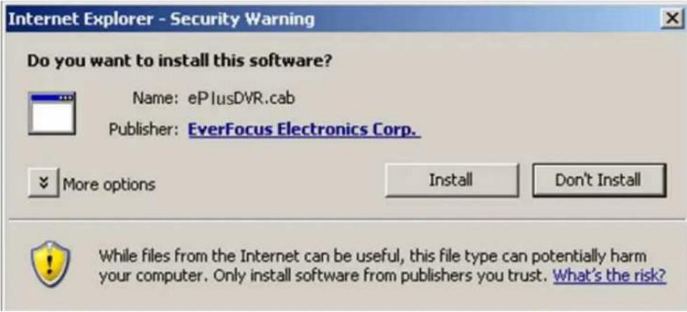
Install the ePlusDVR.cab file when prompted to do so.
Once the file finishes installing, you will return to the same login page as before.
Type in the username and password and click Login to view the cameras.
Default username: admin
Default password: 11111111
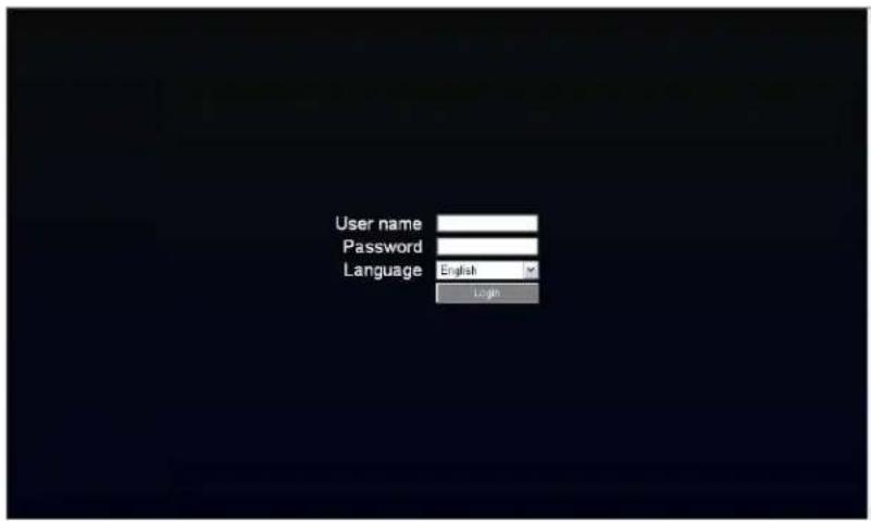
7.2.2 Enabling ActiveX Controls
Note: This section is only necessary if you DO NOT see the yellow ActiveX bar at the top of your browser screen when you first connect to the DVR.
At the top of the Internet Explorer ←indow, click on Tools, then select Internet Options.
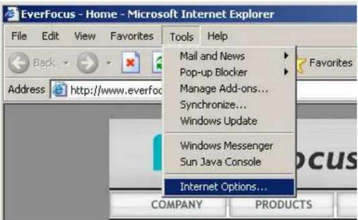
Click the Security tab at the top of the window, then choose Custom Level near the bottom.
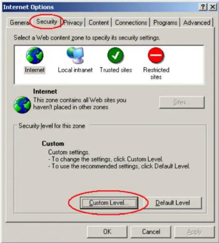
In the Security Settings window, scroll to "Active→ controls and plug-ins"
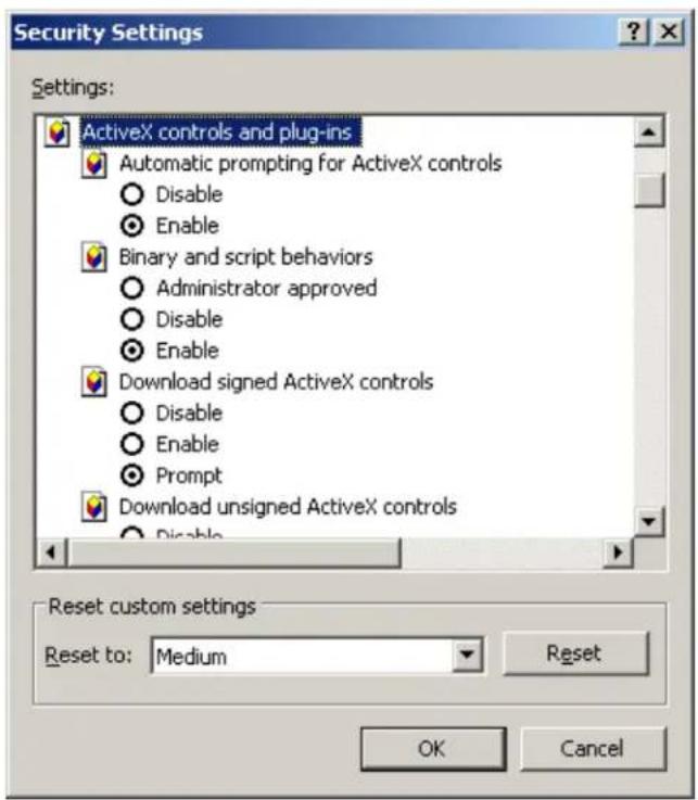
Set the controls as follows:
"Enable":
√ Allow previously unused Active→ controls to run without prompt (Internet Explorer 7 only)
√ Allow scriptlets (IE7 only)
√ Automatic prompting for Active→ controls
√ Binary and script behaviors
√ Display video and animation on a webpage that does not use external media player (IE7 only)
√ Run Active→ controls and plug-ins
√ Script Active→ controls marked safe for scripting
"Prompt":
√ Download signed Active→ controls
√ Download unsigned Active→ controls
"Disable":
√ Initialize and script Active→ controls not marked as safe
Click OK and then choose Yes to change the security settings.
Close the window so you are back at the login screen.
Click the Refresh button to reload the page.
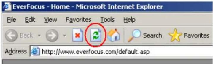
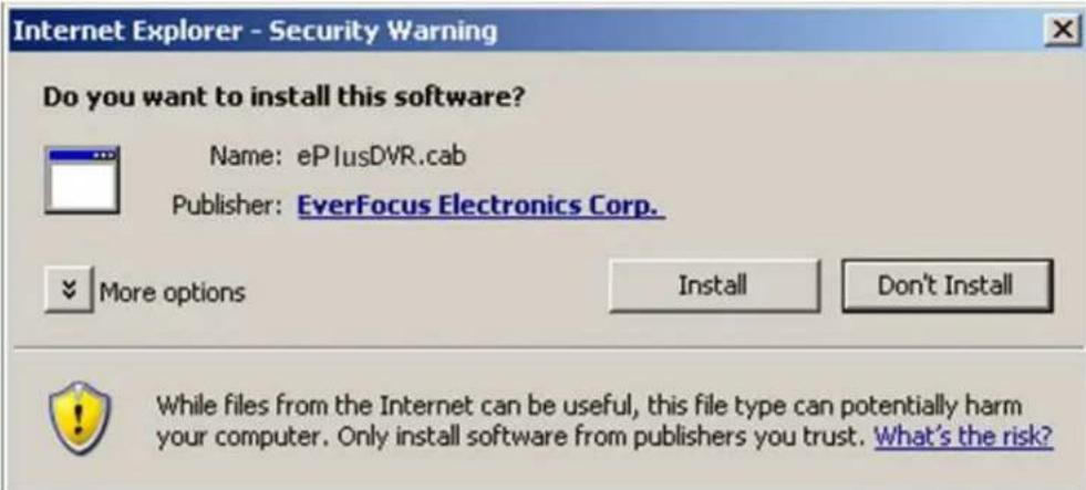
Install the ePlusDVR.cab file when prompted to do so.
Once the file finishes installing, you will return to the same login page as before.
Type in the user name and password and click Login to view the cameras.
Default user name: admin
Default password: 11111111.
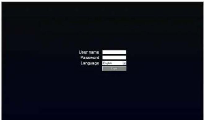
7.3 REMOTE LIVE VIEW
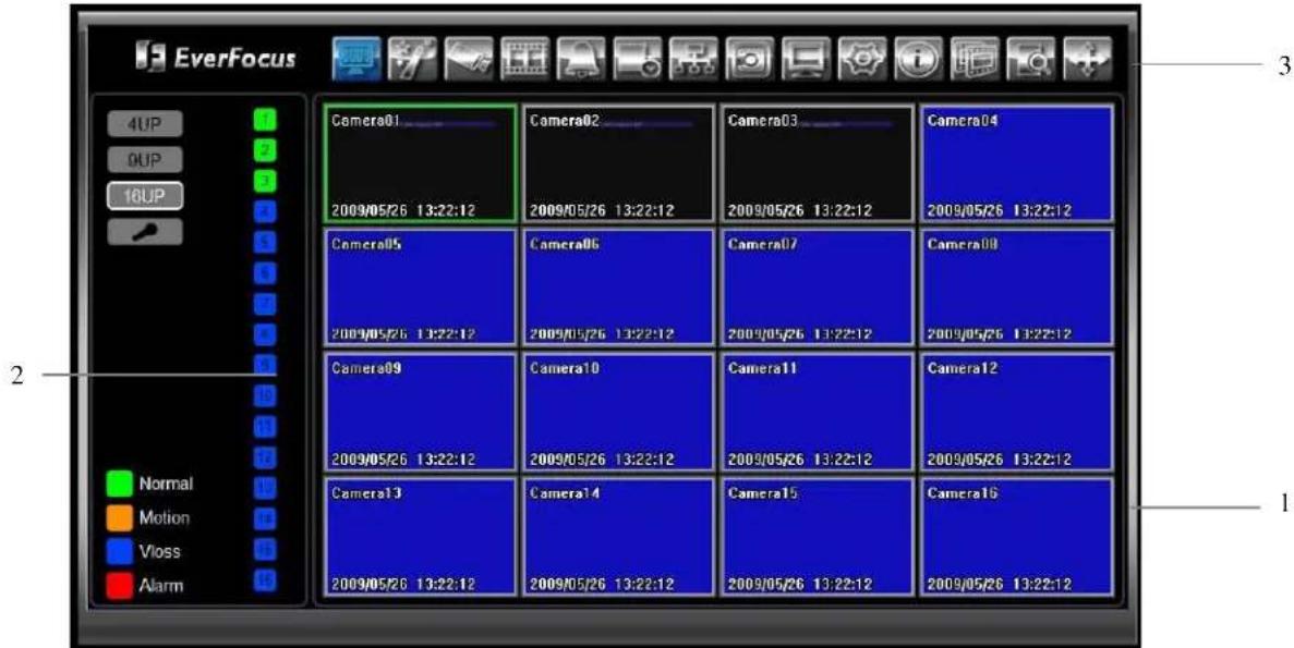
- In the main page, you will see live images in a 16-screen display (or 8 screens, depending on the model).
- The status of each camera is represented by different colors on the left side of the screen. Green means normal; orange indicates a Motion; blue indicates Vloss, red indicates an alarm event. Click on a camera number to switch that camera to full screen. Click on "4UP", "9UP", or "16UP" to display 4, 9, or 16 screens. You can also press "Mic" button to transfer audio to DVR from client side if there has microphone.
- There are 13 icons at the top of screen. The first twelve have the same functions as the icons in the DVR's Main Menu. The last icon is used for PTZ control (described in the next section).
7.4 REMOTE PTZ CONTROL
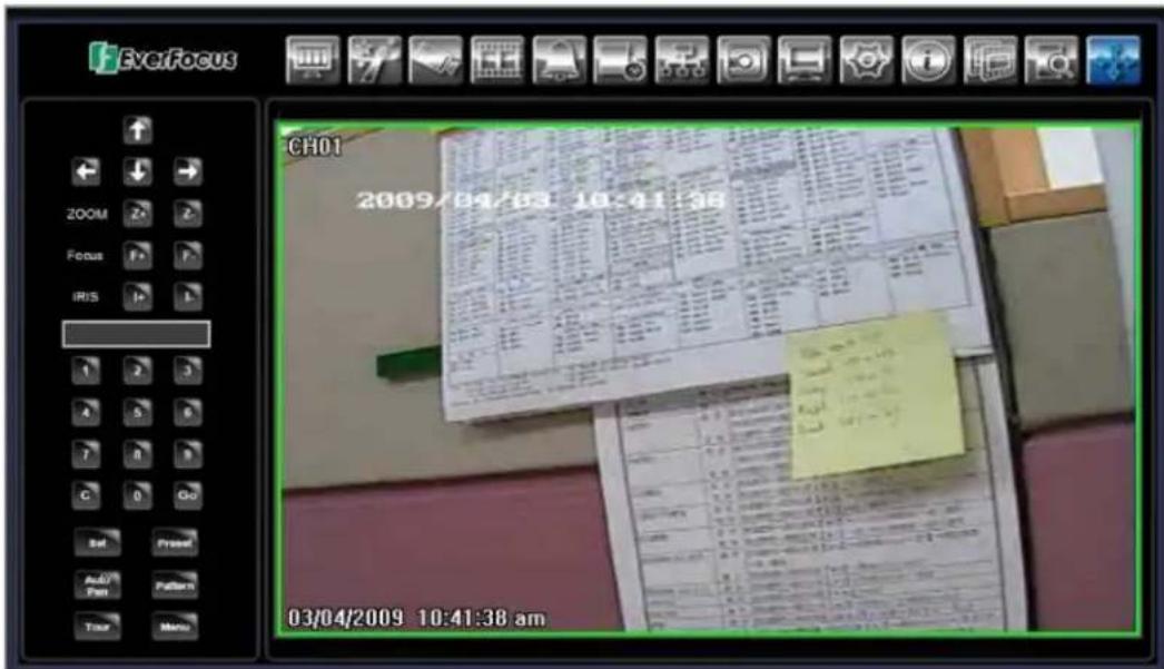
- Use Direction Arrows (up, down, left, right) to move the camera to the desired direction and angle.
- In Zoom option, Click "Z+" to zoom closer or "Z-" to zoom farther away.
- In Focus option, click "F+" to increase the focus or click "F-" to decrease the focus.
- In Iris option, you can increase the amount of light by clicking "I+" or decrease it by clicking "I-".
- To program a preset position
a. Move PTZ camera to the specified position
b. Click "Preset" button
c. Click the number of the desired position (This will be displayed in the box)
d. Click "Set" button
- Steps to jump to a preset position
a. Click "Preset" button
b. Click the number of the desired position
c. Click "Go" button
- Shortcut steps for presets #1-9
a. Click digit 1-9 button without clicking any other buttons
- Steps to delete a preset position
a. Click "Preset" button
b. Click the number of the desired position
c. Click "Delete" button
- Steps to run Auto Pan
a. Click "Auto Pan" button
- Pattern Operation (Pattern is the "0" Tour in Everfocus and Pelco PTZ cameras)
a. Click "Pattern" button
- Steps to run a tour
a. Click "Tour" button
b. Click the number of the desired tour
c. Click "Go" button
- Steps to remove a tour
a. Click "Tour" button
b. Click the number of the desired tour
c. Click "Delete" button
7.5 REMOTE PLAYBACK
To playback the video, press "Search" button. Select from "Time Search", "Event Search", or "Motion Search". For more details about Search setting, please refer to "4.13 Search Setting".
"Event Search" and "Motion Search" will show maximum 400 search result items(near start time)
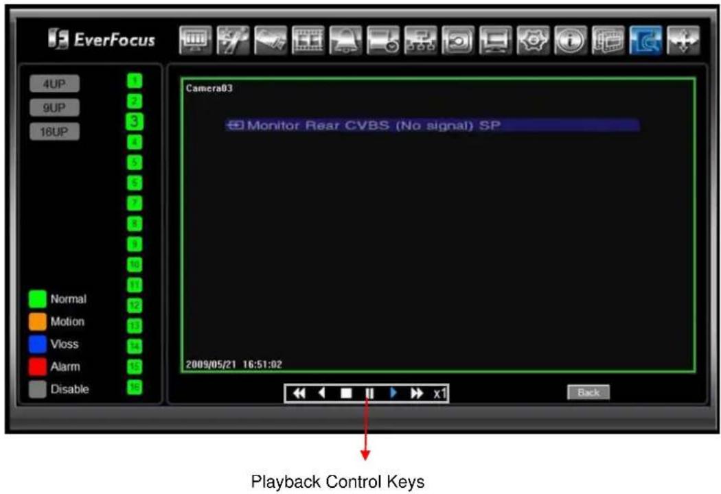
Playback Control Keys:
Step 1. Set up the Network Menu according to the instructions detailed in the Networking chapter. (Make sure that DNS Server 1 is set correctly or DDNS will not work)
Step 2. Go to the website http://everfocusddns.com and check for an available name.
Note: This step is optional, as it is only used to check the availability of host name. If the name is available, proceed to step 3 for DDNS setup.
Step 3. In DVR's Network Menu, go to DDNS. Choose "EverfocusDDNS" for the Server and put in your chosen name for DVR Name.
Step 4. Press "Submit/Update" button to confirm.
Step 5. You should now be able to connect by typing the name you created into the address bar. Example: http://hostname.everfocusddns.com
9 LINKSYS & D-LINK PORT FORWARDING
9.1 LINKSYS PORT FORWARDING
This section will cover a few simple configurations for the Linksys router. This chapter is only to offer some help to the installer and end user. Please understand we DO NOT support this product and will not give tech support on it. If you need additional technical support on this router you must call Linksys.
To access the ←eb-based Utility, launch a web browser and type the Router's default IP address, 192.168.1.1, in the address bar. Then press Enter. A password request page will appear. (Non←indows →P users will see a similar screen.) Leave the User Name field blank. The first time you access the router, use the default password admin. Click the OK button to continue.
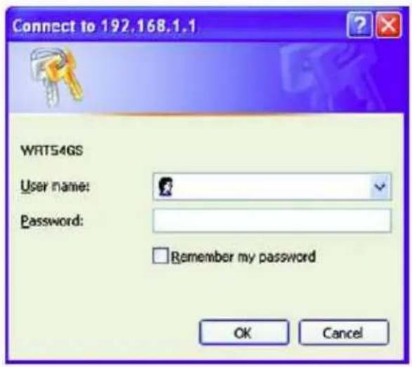
The first screen that appears displays the Setup tab. This allows you to change the Router's general settings. Change these settings as described here and click the Save Settings button to apply your changes or Cancel Changes to cancel your changes.
Click on the "Applications & Gaming" tab.
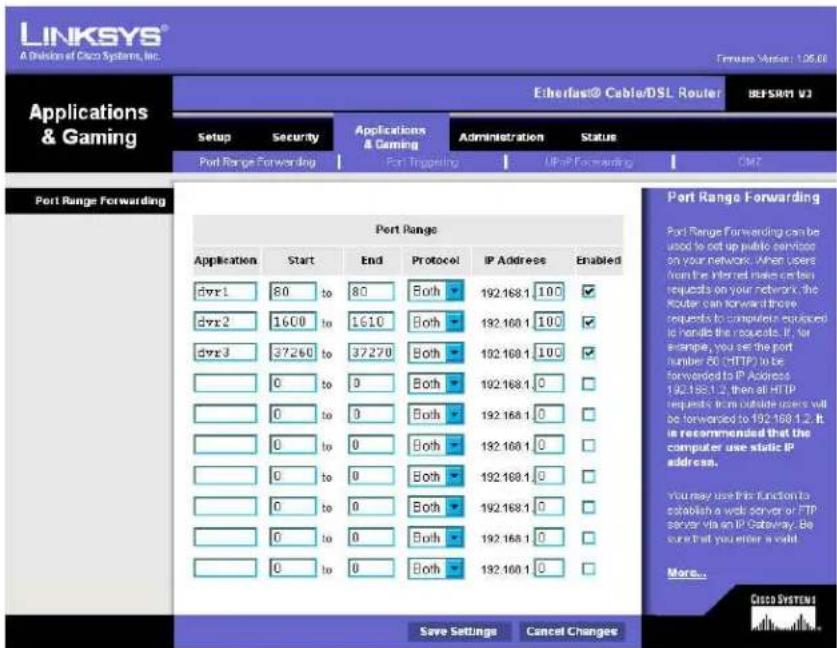
Applications and Gaming allows you to set up public services on your network, such as web servers, ftp servers, e-mail servers, or other specialized Internet applications. (Some Internet applications may not require any forwarding) To forward a port, enter the information on each line for the criteria required. Descriptions of each criterion are described here.
Application - In this field, enter the name you wish to give the application.
Start/End - Enter the starting number of the range under Start and the ending number under End.
Protocol - Enter the protocol used for this application, either TCP or UDP, or Both.
IP Address - For each application, enter the IP Address of the PC running the specific application.
Enable - Click the Enable checkbox to enable port forwarding for the relevant application.
←hen finished making changes, click the Save Settings button to apply your changes or Cancel Changes to cancel them.
Here is an example for how the port information might look:
HTTP 80 to 80 Both 192.168.1.50 Enable
CTRL 1600 to 1600 Both 192.168.1.50 Enable
- Note: If you changed port 80 in the DVR's Network Menu, open that port instead of 80.
9.2 D-LINK PORT FORWARDING
This section will cover a few simple configurations for the D-Link router. This chapter is only to offer some help to the installer and end user. Please understand we DO NOT support this product and will not give tech support on it. If you need additional technical support on this router you must call D-Link.
←henever you want to configure your network or the DI-624, you can access the Configuration Menu by opening a web-browser and typing in the IP Address of the DI-264.
The DI-264 default IP Address is 192.168.0.1.
■ Leave the Password blank
Click OK
■ Type "admin" in the User Name field
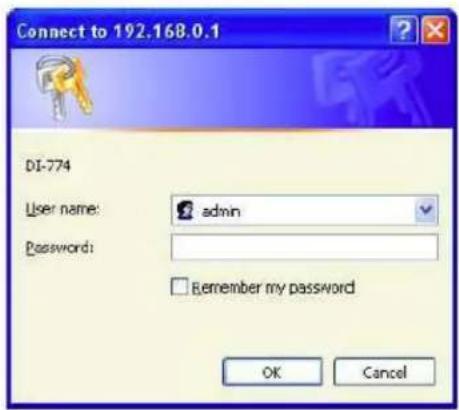
The first screen that shows up is the Home Tab. This is the starting point for all the router's settings and functions.
Click Virtual Servers on the left to bring up the following screen.
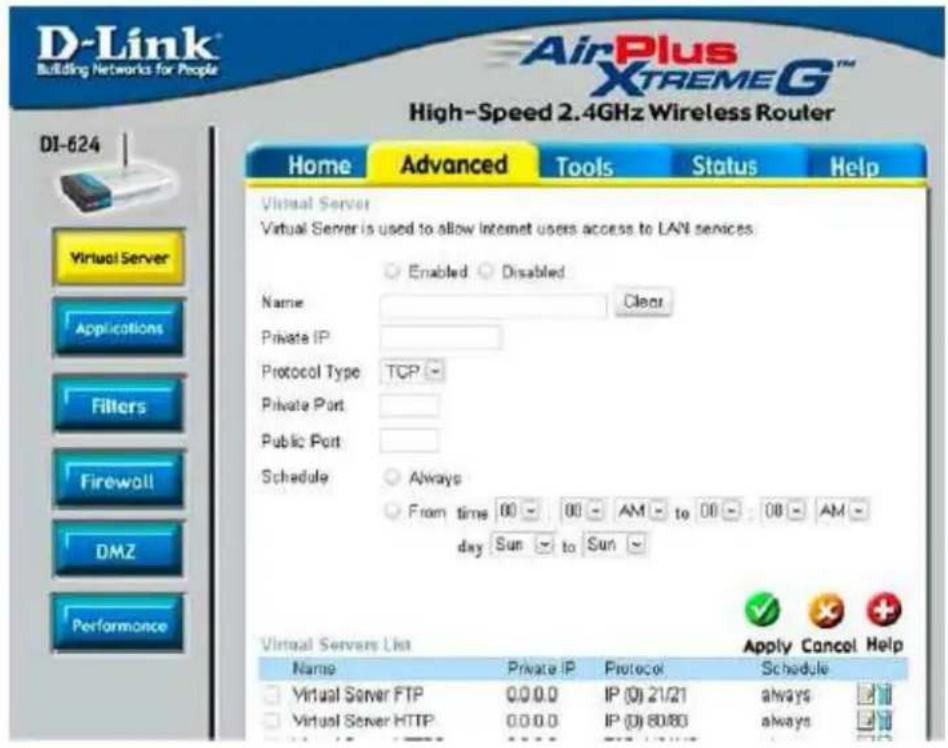
Virtual Servers allows users who are connecting remotely to access services on the router's Local Network. The functions of each field are described below.
Virtual Server - Select Enabled or Disabled
Name - Enter the name referencing the virtual service
Private IP - The IP address of the device running the local services.
Protocol Type - The protocol used for the virtual service.
Private Port – The port number that the service uses on the LAN (Local Area Network).
Public Port - The port number that the services uses on the ←AN (←ide Area Network).
Schedule – The time period the virtual server will be active.
←hen you have input all the information for a virtual server, click on Apply to add it to the list at the bottom or Cancel to clear all fields.
Here is an example of the information for each service:
Name Private IP Protocol Private Port Public Port Schedule
HTTP 192.168.1.50 Both 80 80 Enable
CTRL 192.168.1.50 Both 1600 1600 Enable
- Note: If you changed port 80 in the DVR's Network Menu, open that port instead of 80.
10 TROUBLESHOOTING
If you have problems with the system, run through the following checklist to see if you can solve the problem.
☐ The DVR will not go into record mode.
Bring up the DVR's Menu and check under the Camera Menu. Verify that all connected cameras are checked as "Installed" and that Record Mode is set to "Continuous".
■ Check the Disk or Information Menus and verify that the internal hard drive is being detected.
☐ The DVR displays no picture.
■ Make sure the monitor is connected to either the Video Out port or the VGA port. If the monitor has multiple inputs, make sure it is on the correct display setting.
■ Check that the monitor cables are good.
■ Verify the recorder is getting the correct amount of power.
☐ There is no display coming from one of the channels on the DVR.
In the DVR's Camera Menu, make sure that all cameras are checked as "Installed" and unchecked for "Covert".
- Verify that all cameras are connected on the "Input" row on the back of the DVR.
If there is still no picture, connect a working camera to the port that has no picture. If you get an image, the problem is coming from the camera.
☐ I cannot connect to the recorder via the internet.
- Check that the DVR's ports are forwarded correctly in the router.
■ Verify that your Internet Service Provider does not block any ports.
■ Make sure you are using the correct IP address given by the ISP, or, if you have a Dynamic IP, check if the number has changed.
APPENDIX A: TIMING OF ALARM MODES
Transparent Mode
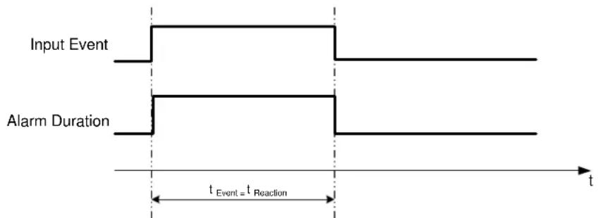
t Event: Duration of alarm input source (motion, contact, system events...)
t_reaction : Resulting duration for this alarm mode, related to event record, alarm outputs, OSD message, buzzer
Timeout + Transparent Mode
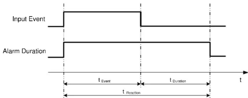
t Event: Duration of alarm input source (motion, contact, system events...)
t Duration: Alarm duration for timeout, defined in the event setup menus
t_reaction : Resulting duration for this alarm mode, related to event record, alarm outputs, OSD message, buzzer
Timeout Mode
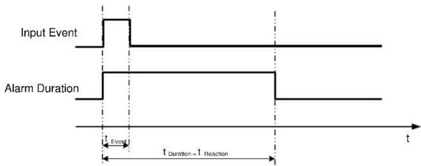
other
| Event Type | Time Segment Start | Time Segment End | | ---------------- | ------------------ | ---------------- | | Input Event | t | t | | Alarm Duration | t | t |t Event: Duration of alarm input source (motion, contact, system events...)
t Duration: Alarm duration for timeout, defined in the event setup menus
t reaction: Resulting duration for this alarm mode, related to event record, alarm outputs, OSD message, buzzer
Permanent Mode
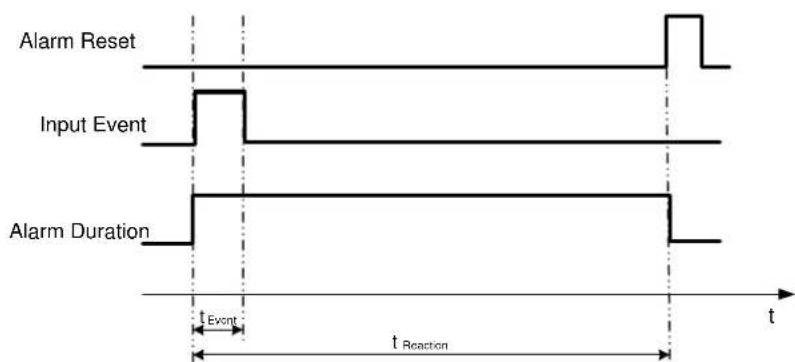
t Event: Duration of alarm input source (motion, contact, system events...)
t Duration: Alarm duration for timeout, defined in the event setup menus
t reaction: Resulting duration for this alarm mode, related to event record, alarm outputs, OSD message, buzzer
Timeout Mode: Retrigger of Alarms
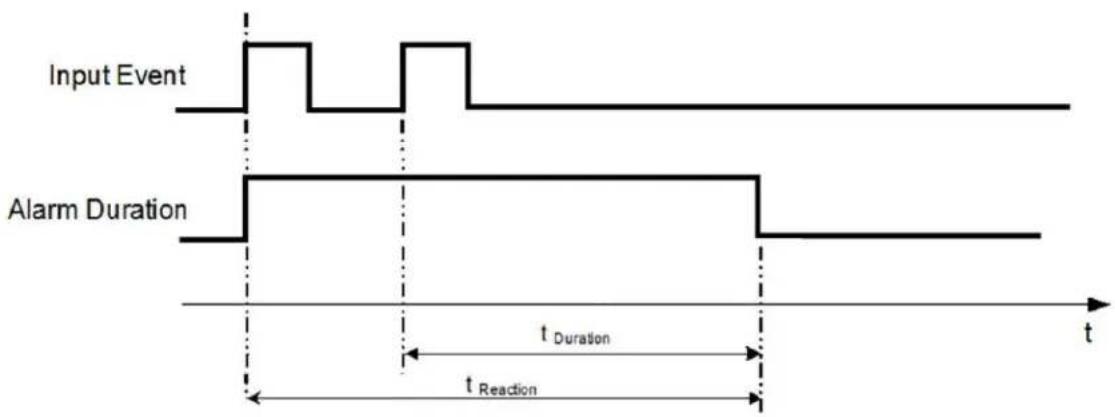
line
| Event Type | Time Segment | | ---------------- | -------------------- | | Input Event | 0 | | Alarm Duration | t_Duration | | Alarm Duration | t_Reaction |t Event: Duration of alarm input source (motion, contact, system events...)
t Duration: Alarm duration for timeout, defined in the event setup menus
t_reaction : Resulting duration for this alarm mode, related to event record, alarm outputs, OSD message, buzzer
Timeout+Transparent Mode: Retrigger of Alarms
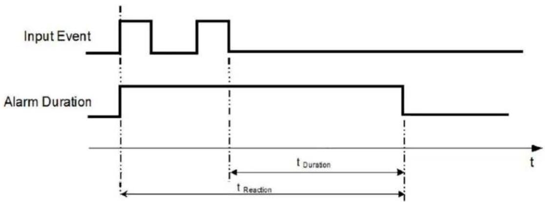
line
| Event Type | Time Segment | | ---------------- | -------------------- | | Input Event | 0 | | Alarm Duration | t_Duration | | Alarm Duration | t_Reaction |t Event: Duration of alarm input source (motion, contact, system events...)
t Duration: Alarm duration for timeout, defined in the event setup menus
t_reaction : Resulting duration for this alarm mode, related to event record, alarm outputs, OSD message, buzzer
APPENDIX B: CHANGING RULE FOR
EXPRESS SETUP
Case 1:
Record Mode: Normal + Event
Record With: Recording days
DVR will Auto adjust Quality and Event frame rate to match the Recording days which user selected:
According to resolution, event hours and assumption above, DVR will select one set of suitable quality and event frame rate from Changing Order 1 to 8. If DVR can't match require record days from 8 sets of Change Order, it will just use the set of Changing Order 8.
| Changing Order 1 | 2 | 3 | 4 | 5 | 6 | 7 | 8 | |
| Normal Frame Rate | 1 | 1 | 1 | 1 | 1 | 1 | 1 | 1 |
| Quality Sup | erior | Standard | Low Low | Low Low | Low Low | Low | ||
| Event Frame Rate 30 | 30 | 30 | 15 | 10 | 7.5 | 5 | 1 |
Case 2:
Record Mode: Event Only
Record With: Recording days
DVR will Auto adjust Quality and Event frame rate to match the Recording days which user need:
According to resolution, event hours and assumption above, DVR will select one set of suitable quality and event frame rate from Changing Order 1 to 8. If DVR can't match require record days from 8 sets, it will just use the set of Changing Order 8.
| Changing Order 1 | 2 | 3 | 4 | 5 | 6 | 7 | 8 | |
| Quality | Superior | Standard | Low Low | Low Low | Low Low | Low | ||
| Event Frame Rate | 30 | 30 | 30 | 15 | 10 | 7.5 | 5 | 1 |
Case 3:
Record Mode: Normal + Event or Event Only
Record With: Preset Setting
DVR will apply setting in below table to all cameras according to different Preset Setting.
| Preset Setting Option | Camera Item Apply value | |
| Best Quality | Quality Superior | |
| Normal Frame Rate | Max recording frame rate of DVR | |
| Event Frame Rate 30 | ||
| Standard Quality | Quality Standard | |
| Normal Frame Rate | Half of max recording frame rate of DVR | |
| Event Frame Rate 30 | ||
| Extended Quality | Quality Basic | |
| Normal Frame Rate | 1 | |
| Event Frame Rate 10 | ||
EverFocus Electronics Corp.
Headquarter Office
12F, No.79 Sec.1 Shin-Tai Wu Road,
Hsi-Chi, Taipei, Taiwan
Tel: +886-2-26982334
Fax: +886-2-26982380
Beijing office
Room 609, Technology Trade Building.
Shangdi Information Industry Base,
Haidian District, Beijing China
Tel: +86-10-62971096
Fax: +86-10-62971423
European Office
D-46446 Emmerich, Germany
Tel: +49-2822-9394-0
Fax: +49-2822-939495
Japan Office
5F Kinshicho City Building, 2-13-4 Koto-
bashi, Sumida-Ku, Tokyo, 130-0022, Japan
Tel: +81-3-5625-8188
Fax: +81-3-5625-8189
USA California Office
1801 Highland Ave. Unit A
Duarte, CA 91010, U.S.A
Tel: +1-626-844-8888
Fax: +1-626-844-8838
USA New York Office
415 Oser Ave Unit S
Hauppauge, NY 11788
Sales: +1-631-436-5070
Fax: +1-631-436-5027

Your EverFocus product is designed and manufactured with high quality materials and components which can be recycled and reused.
This symbol means that electrical and electronic equipment, at their end-of-life, should be disposed of separately from your household waste.
Please, dispose of this equipment at your local community waste
collection/recycling centre. In the European Union there are separate collection systems for used electrical and electronic product. Please, help us to conserve the environment we live in!
- PARAGON264x4/264x2 Series DVR
- PARAGON264x4/264x2 Series DVR Instruction Manual
- Safety Precautions
- Federal Communication Commission Interference Statement
- TABLE OF CONTENTS
- PRODUCT OVERVIEW .... 1
- INSTALLATION....11
- MOUSE AND FRONT PANEL OPERATION 21
- GENERAL DVR OPERATIONS.... 27
- DVR CONFIGURATION....42
- NETWORKING OVERVIEW 92
- REMOTE OPERATION FROM BROWSER.... 105
- EVERFOCUS DDNS SETUP 115
- LINKSYS & D-LINK PORT FORWARDING 116
- TROUBLESHOOTING 121
- APPENDIX A: TIMING OF ALARM MODES....122
- APPENDIX B: CHANGING RULE FOR EXPRESS SETUP.... 125
- PRODUCT OVERVIEW
- FEATURES
- PACKAGE CONTENTS
- SPECIFICATIONS
- FRONT PANEL
- REAR PANEL
- HDD INSTALLATION
- INSTALLATION
- VIDEO INPUTS/OUTPUTS INSTALLATION
- AUDIO INSTALLATION
- AUDIO RECORDING FUNCTIONALITY:
- ALARM / CONTROL CONTACTS INSTALLATION
- Alarm Input Contacts
- Control Input Contact
- Alarm Output Relay
- RS-485 keyboard / PTZ Installation
- General RS-485 bus installation
- RS-485 socket pin assignment
- EKB-500 connection with network patch cable
- EKB-500 connection to several DVRs
- Speed Dome Installation
- RS-232 Connection
- USB-Mouse installation
- NETWORK CONNECTION
- Direct PC Connection through Crossover Network Cable
- Network Connection through Patch Cable
- FINAL INSTALL PROCESS
- MOUSE AND FRONT PANEL OPERATION
- How to select a channel / Enable audio
- OSD Root Menu
- Operation in Configuration Menu
- Component Options
- \* Note about on-screen keyboard:
- GENERAL FRONT PANEL OPERATION
- How to select a channel / Enable audio
- OSD Root Menu
- Front Panel Key Review
- Operation in Configuration Menu
- Component Options
- GENERAL DVR OPERATIONS
- RECORD
- LOGIN
- SELECT CAMERA OPERATION
- PLAYBACK
- PTZ
- General PTZ control
- Express control PTZ
- LAYOUT
- Bring to full screen mode
- CHANNEL SWITCHING
- DISPLAY
- SEQUENCE
- MONITOR
- Switch control by using a mouse
- Switch control from front panel
- Operation of Call Monitor OSD
- ZOOM
- SEARCH
- Time Search
- Event Search
- Motion Search
- COPY
- LOGOUT
- DVR CONFIGURATION
- EXPRESS
- Record Mode:
- Record With:
- Network Type:
- CAMERA SETTING
- Basic Setting
- Video Adjust
- Motion
- Video Loss
- RECORD & PLAY SETTING
- Record
- Built-in Cal.
- Play
- ALARM & EVENT SETTING
- Alarm
- Event
- Fan Failure:
- HD Temperature:
- HD Failure:
- HD Full:
- Power Loss:
- Record Stop:
- Network Loss:
- SCHEDULE SETTING
- Express Setup
- Holidays
- Schedule
- To Set Schedule using Mouse
- Schedule Setting from front panel
- Editing Timezone:
- NETWORK SETTING
- LAN
- DDNS
- Alarm Server
- DISPLAY SETTING
- Monitor OSD
- Main Monitor
- Call Monitor
- Main M/T SEQ
- Call M/T SEQ
- DISK SETTING
- Disk
- Lock/Format
- SYSTEM SETTING
- Date/Time
- Daylight Saving
- User
- Add
- Edit
- I/O Control
- RS232
- RS485
- Control
- Misc.
- Firmware
- Configurations
- INFORMATION SETTING
- System
- System
- Network
- Status
- Log Type:
- Networking Overview
- Introduction to TCP/IP
- Subnet Masks
- Gateway Address
- Virtual Ports
- Pre-Installation
- What is your Network Setup?
- Simple One to One Connection
- Crossover Ethernet Cable Pin outs:
- Connection Procedure:
- Direct High Speed Modem Connection
- Straight Through Ethernet Cable Pin outs:
- Router or LAN Connection
- To set DVR for Internet Connection through router
- REMOTE OPERATION FROM BROWSER
- CONNECTING TO DVR
- BROWSER SECURITY SETTING
- Installing ActiveX controls
- Enabling ActiveX Controls
- "Enable":
- "Prompt":
- "Disable":
- REMOTE LIVE VIEW
- REMOTE PTZ CONTROL
- REMOTE PLAYBACK
- LINKSYS & D-LINK PORT FORWARDING
- LINKSYS PORT FORWARDING
- D-LINK PORT FORWARDING
- Virtual Server - Select Enabled or Disabled
- TROUBLESHOOTING
- APPENDIX A: TIMING OF ALARM MODES
- Transparent Mode
- Timeout + Transparent Mode
- Timeout Mode
- Permanent Mode
- Timeout Mode: Retrigger of Alarms
- Timeout+Transparent Mode: Retrigger of Alarms
- APPENDIX B: CHANGING RULE FOR
- EXPRESS SETUP
- Case 3:
- Record Mode: Normal + Event or Event Only
- Record With: Preset Setting
- EverFocus Electronics Corp.
- Headquarter Office
- Beijing office
- European Office
- Japan Office
- USA California Office
- USA New York Office
Brand : EverFocus
Model : Paragon264 2TB
Category : Voice recorder