Digitstat+C RF - Thermostat Drayton - Free user manual and instructions
Find the device manual for free Digitstat+C RF Drayton in PDF.


| Product Type | RF Cylinder Thermostat (Transmitter + SCR Receiver) |
| Model | Digitstat+C RF |
| Power Supply (Transmitter) | 2 x AA 1.5V alkaline batteries |
| Power Supply (Receiver) | 210V AC 50Hz |
| Radio Frequency | 413 MHz |
| Radio Signal Range | 30m typically (may be affected by walls) |
| Temperature Range | 40 to 70°C (adjustable setpoint) |
| Control Accuracy | ±8°C |
| Ambient Temperature (Operating) | 0°C to 50°C |
| Ambient Temperature (Storage) | -20°C to 53°C |
| Display | Digital LCD showing setpoint and current temperature |
| Setpoint Adjustment | Rotary dial, 1 click = 5°C |
| Minimum Temperature Setting | 40°C (adjustable down to 40°C) |
| Maximum Temperature Setting | 70°C (adjustable up to 75°C) |
| Manual Override | Via Override button on SCR |
| Tamper Proofing | Set Min and Max to same value |
| Battery Low Indicator | Flashing battery symbol on display (approx. 30 days remaining) |
| Fault Display | E2 for sensor failure or out of range |
| Receiver LED Indications | Green: demand for heat; Red: signal received (flashes 7s every 5 min), continuous red: no signal or low battery |
| Mounting (Transmitter) | Wall mounting near hot water cylinder, check signal strength first |
| Mounting (Receiver) | Near boiler/heating system, at least 30cm from metal objects |
| Wiring (Receiver) | Hard-wired, double insulated, no earth required |
| External Sensor Connection | 2-core cable, sensor positioned 1/3 up cylinder |
| Applicable Standards | EN62732-1:2021, EN60730-2-7:1952, Low Voltage Directive 2001/95/EC |
Frequently Asked Questions - Digitstat+C RF Drayton
User questions about Digitstat+C RF Drayton
0 question about this device. Answer the ones you know or ask your own.
Ask a new question about this device
Download the instructions for your Thermostat in PDF format for free! Find your manual Digitstat+C RF - Drayton and take your electronic device back in hand. On this page are published all the documents necessary for the use of your device. Digitstat+C RF by Drayton.
USER MANUAL Digitstat+C RF Drayton
Power Supply: 2 x AA SiO, 1.5V alkaline batteries
Radio frequency:
RF version: A13 Mio
Radio Signal Range: 30m typically. The range may be affected by the composition / density and number of walls between the Digustat RF and SCR.
Temperature Range: 40 to 70°C Control Accuracy: ±8°C
Ambient Temperature: Operating 0°C to 50°C /
Storage -20°C to 53°C
Applicable Standards
EN62732-1 2021, EN60730-2-7.1952
2001/95/EC Low Voltage Directive
8/31/EC. EML Deschus
8.30226-1
Mounting
Transmitter: Suitable In
Direct menu by date opening
6.5mm-2 core cable between sensor and conductor of 95-degree
and Digital-CR Transmitter
SINGLE CHANNEL
RECEIVED
Power Supply: 210V AC SOHz
Switch Type & Rating: S*DT (sellage free) 2011A 23106 AC, w
21V AC (DC)
Wiring: Designed for head wiring only to comply
with current IFE regulation.
Reception Frequency:
413 MPa
Location
Cylinder Thermostat
The transmitter should be located in a convenient position for the end user, close to the domestic hot-water cylinder being controlled
signal strength
Before doing the Davast CW to the wall it is recommended in order
Check the Signal Strength from that location. To do this, remove the batteries, press and hold the set button whilst refitting the battery, keep the set button held and after a few seconds the display will show VF which indicates that the Distnet-CRF is continuously seeking an OFF signal to view the SCR recovery. Leave the Distnet-CRF in position and return to view the SCR. If the red LED is community flashing, this indicates a good signal. If the red LED is still flashing, this indicates a poor signal and you need to reposition the Distnet-CRF and the red LED is flashing.
'Alcan the signal strength has been confirmed remove the batteries to cover the wire and follow the installation instruction.
Before Installation
If you do not have the knowledge to install the thermostat safely then you must arrange for a competent electrician to install it for you. Wiring must confirm to the current IIE regulators.
Prior to commencing the installation you must ensure the mains supply is switched off.
Remove battery
compartment

Loosen screw


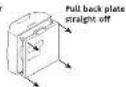
To wire the external sensor, snap out the cable entry strip on the bottom right edge of the thermostat cover.
Cylinder Thermostat sensor
Undip the housing to show the terminal block. First, connect a 2-core cable to the sensor, cut to the required length to reach the thermostat position. Connect to the sensor in the position shown and fold wires back through the cable grip & cut through the cable entry, re-assemble the housing.

Clip the spacer provided onto the sensor housing.

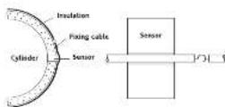
The sensor should be installed approximately one-third of the way up the last water cylinder. With pre-escalated cylinders, mark the posture and size, and remove just enough imutation to allow the sensor to fit against the metal of the cylinder in the recess fenced.

The plastic covered spring fixing cable should be cut to an un- stretched length of approximately 60.75mm (2/8" 3") less than the circumference of the cylinder and the hook and eyelet should be screwed into the ends. Stretch the cable round the cylinder, over the insulation, and position it in the groove across the front of the sensor housing. Engage the hook and eyelet.
WIRING
Cylinder Thermostat

1940054301 82 E
Drayton
Digistat+C RF
RF Cylinder Thermostat
Model:
13616
CE
Inveroys Controls Europe Technical Helpline: +44 (2) 845 130 7722 www.drayoncontrols.co.uk

User Guide


What is a cylinder thermostat?
an explanation for Householders
A cylinder thermostat switches on and off the heat supply from the boiler to the hot-water cylinder. It works by sensing the temperature of the water inside the cylinder, switching on the water heating when the temperature falls below the thermostat setting, and switching it off once this set temperature has been reached.
Turning a cylinder thermostat to a higher setting will not make the water heat up any faster. How quickly the water heats up depends on the design of the heating system, for example, the size of boiler and the heat exchanger inside the cylinder.
The water heating will not work if a time switch or programmer has switched it off. And the cylinder thermostat will not always switch the heater off, because the heater sometimes needs to heat the radiators.
Cylinder thermostats are usually fitted between one quarter and one third of the way up the cylinder. The cylinder thermostat will have a temperature scale marked on it, and it should be set at between 60°C and 65°C, then left to do its job. This temperature is high enough to kill off harmful bacteria in the water, but rising the temperature of the stored hot water any higher will result in wasted energy and increase the risk of wading.
If you have a boiler control thermostat, it should always be set to a higher temperature than that of the cylinder thermostat. In most boilers, a single boiler thermostat controls the temperature of water sent to both the cylinder and radiators, although in some there are two separate boiler thermostats.
Your new thermostat with digital display.

Thermotat Display - Features & Characters

FEATURES
This product has the following user adjustable settings.
- Required temperature (temperature setpoint)
- Minimum & Maximum temperature settings
Simple Setting or Operating
To set the required temperature
- The display normally shows the current output
The display normally shows the current sepoint
+10 adjust the required temperature, turn the dial clockwise to increase or anti-clockwise to
decrease. (1 click = 5°C), the LCD will display
the temperature setpoint as it is being
adjusted and 'SET' will be displayed. After a
few seconds the display will return to normal
operation and will display the current setpoint.
While adjusting the temperature during normal
operation, when you reach the maximum (70%
default) or minimum (40-C default) possible setting,
one further click will put the product in to a
positive on (after 70°C) or positive off (after 40
Thermocetal within the Installation Guide for further
Thermostat within the instead inside for further details.
ADVANCED FEATURES
To change the user adjustable settings
• To enter the 'User' menu press and hold the 'Set' button for
more than 5 but less than 10 seconds - the display will show "Hi"
as MoAH
[1]
[1]
- If the diet is turned completely one click then 20 Minimium
temperature setting will be displayed and if turned one more click
clockwise then 'H' (Maximum temperature setting) will be displayed
Changing the Maximum Temperature Setting
- To adjust the maximum temperature setting enter the last menu
la deliche
[Unreadable]
n
- Then press the 'set judgment rate, the current selling is shown.
- 2017年
11 70
• Revere the daily allowance to increase the interest to treasury
setting (max. 75°) and anti-clockwise to reduce the maximum
temperature setting (min 40°C or min temp. setting). Press the Se
button to confirm, the copy will show
1
1
04364021 855
Changing the Minimum Temperature Setting
• To adjust the minimum temperature setting enter the user
menu as described above, then rotate the dial clockwise until 'Lo'
B. GOMING
Lo
1.2.3.4.5.6.7.8.9.10.11.12.13.14.15.16.17.18.19.20.21.22.23.24.25.26.27.28.29.30.31.32.33.34.35.36.37.38.39.40.41.42.43.44.45.46.47.48.49.50.51.52.53.54.55.56.57.58.59.60.61.62.63.64.65.66.67.68.69.70.71.72.73.74.75.76.77.78.79.80.81.82.83.84.85.86.87.88.89.90.91.92.93.94.95.96.97.98.99.100
- Then press the 'Set' button, the current setting is shown
UC
[ ]
- Rotate the dial clockwise to increase the minimum temperature setting (max. 70°C or max. temp. setting) and anti-clockwise to reduce the minimum temperature setting (min 40°C). Press the Set button to confirm, the display will show.
1
LO
While adjusting the settings within the menu, when you reach the maximum or minimum possible setting the display will flash to indicate you cannot adjust the product further.
To return to normal operation, either press the Set button for more than Sies or wait for 1 minute and it will return automatically.
SCR RECEIVER
SCR (Receiver) Normal Operating Mode
• Once the 'Wireless System' has been commissioned, there should
be little need for any user interaction with the SCR.
- During normal operation the red and green LEDs will occasionally
be on, there signify the following
Green LED
The green LED will be on when there is a demand for heating, and
off when there is no demand.
RED LED
The red LED will flash for 7 seconds, approximately every 5 min. For this device that a video signal is being received from
the Dargat+RF unit
Situations Requiring Attention
Red LTD continually flashes
- This denotes that the battery is the Fungate+PE unit, we
- This denotes that the battery is 100% of the Big 9.31+40% one are approaching the end of their life (see "battery replacement")
(1) 2023年1月1日
Red LED continually on
- This denotes that the SCR has been unable to receive a radio
signal from the Digital+RF unit. This may be caused by the
to me by being a real (see safety replacement) or time temporary interference with the radio signal.
To erase and part the spin, go to the Digit+RS unit and open
to each, and the signal is so to be displayed. For one and open the battery drawer, after a few seconds (the display will go blank)
close the battery drawer and then reset to your desired
Temperature. If the radio signal has been successfully trater
and received the Red LED M104 for 7 seconds then go off
- If the red LED stays on, there may be some other room. require the attention of a healthy organic decision.
Manual Override
• The heating can be manually switched on and off by using the
'OVERIDE' button on the SCR in a fault situation, even though
The red LED will stay on until a satisfactory signal is rem + Once the SCR receiver a satisfactory alarm sign, it will
Once the self-reception is an inflammatory signal, typically automatically reset itself for normal operation.
TAMPER PROOFING
To hamper proof the product i.e. prevent unauthored adjustment of
the product set the Mn and Mac temperature to the same desired
value
FAULT DIAGNOSIS
if the display shows E2, the following faults could have occurred
-
External temperature sensor has failed
-
Ambient temperatures is outside product refracting temperatures range
-
External space has been used (nonproperty).
-
Datalyse seminus certi adu mirofeciy
E2
BATTERY REPLACEMENT
- When the batteries are getting low (approx 30 days battery
life remaining) the battery symbol will flash in the display, it is recommended in charge for batteries given by name.
Recommended to change the interests during this period.
After a plan 30 days, a condition battery ignition only will be shown in the diary and the unit will remain GET.
- 2017年1月1日
1
How to replace the batteries
Remove battery
compartment

Remove the battery compartment by pinching the labs and
withdrawing downwards. Replace the spent-batteries with 2 x AA 1.5V
alkaline batteries ensuring correct compartment pressing fully home.
INSTALLATION OF SCR

If you do not have the knowledge to install the SCR safely then you must arrange for a competent electrician to install it for your. Writing must conform to the current IEE regulations.
Prior to commencing the installation you must ensure the man.
supply is switched off.
Installation instructions
Read all installation and commissioning instructions before
proceeding
Do not switch on until ready to commission.
The system wiring must be able to be fully disconnected from the
mall's supply by a switch incorporated in the mixed wiring having a contact separation of at least 3mm on both poles. Bused x 30
(3) 2016年5月
Location
The Digital SCI (receiver) should be mounted in a convenient
position close to the combiculator or central heating system using
centre. It can should be taken not to mount the SCR in a position where it is surrounded by metal objects or makes voltage cable, as
where it is sun-bounded by metal objects of main voltage case, at this may interfere with the radio signal.
For the best performance install in an open space, at least 30cm
distante from any metal objects including wall hozen and bolder hinging.
It is recommended that the SCR is mounted on the wall nearest the first
location of the Digital +CRF thermostat and not less than 30cm from
the boiler side panel
Warning: installing the SCR too close to the metal side panel or
main cables may interfere with the radio signal.

Fixing (minimum wall plate clearances shown)
- Loosen the securing screws, remove the wallplate, and 7 surface
waring is to be used, snap out the cable entry strip on the bottom
edge of the wallplate with a pair of piers.
- Fix the wallplate, terminals at the top, either direct onto the flat wall plate and end of a flat woodboard on an outlet.
wall using wall pugs and no 6 x1 wood screws or on a hash mounting single condue box using MLX 5.16 screws. Minimum
wallplate clearances are shown:
- Complete the wiring to the SCR wallplate in accordance
relevant diagram to comply with current EE regulation.
- Place the SCR onto the wallplate and tighten the securing screws.
SCR wallplate clearances

Electrical

This product is double insulated and does not require an earth
connection. The SCR should be wired to the combi boiler or central
healing wing using the correct type of cane or net. The sick should be word in replace hard yard room or programmable. thermotoa given in the system or is able to play a game. Alex
check other manufacturers instructions for compatibility
Standard for all models
IMPORTANT MULTIZONE INSTALLATIONS ONLY
If more than one wireless system is fitted within the same property.
ie. for controlling 2 or more zones (mult-zone) it is essential that the
Digital RF units are matched correctly to the relevant SCR. This is equally achieved by communique each Digital and SSTR in him.
early achieved by commissioning each original and 30 P-10m.
- Install see installation and optional and off-power on to the SCR (received). To separate programmes is fired, ensure that it is
Switched on. The red LED should come on.
- Push the 'overide' button on the SCR once. The green LED should
also come on. Check to see if the boiler and/or motorized valve
are working
- To enter 'team' more push the button marked, followed by 2
(2) 1940, and told both depressed together. The red LED should flush (no.) seconds and then no work here the 1974 is
means into the 2 seconds and then go to the depaying the A.K. it is learn mode. Release both buttons.
-
The red and green LED's should be
-
Ties the Fintet's and hold it within right of the
-
Take the capital for all risks, a month light to the next year cash than one metre.
-
insert the batteries into the holder and slide them into the
Digitat RF until the drawer clicks into place.
- The Digital RF should now chlorize the actual room temperature. If
the and has been stored in a cold place, it may take time to warm up.
B. As soon as the battery compartment is slid back into place, the
led LED on the SCR should flash for 7 seconds and then go out.
The green LED may be on or off depending temperature at the time of comminancing.
-
of the cold SP movie on his drama track
-
If the Red LED remains on, side down the battery drawer on the Diestat RE check the batteries restings are correct, and once the
Display has faded, repeat steps 5 to 8.
- increase the SET temperature on the Digital RF by rotating the
dist clockwise until a flame symbol appears, in the left hard
segment of the display
- The red LED on the SCR should flash for 7 seconds. This confirms
that the radio signals is being soft and received. After 7 seconds, the red LED should go out and the green are come on.
(2) if the 100% should be cut, the 100% came on.
- Check to work of
13 Decrease the SET temperature on the Dinitat RE by entering the
-
Decrease the set of temperature on the crystal ring, dial anticlockwise until the flame symbol disappears.
-
The end I/F on the S/8 should finish (or 2 seconds. After 2
seconds both the red and green LEDs should go out. Check that
the bolar and/or motorized valve have powered down
- Place the Digistat RF in the chosen operating position. (see
Digital RF location section and repeat steps 10 to 14. Once
you have committed the system operates correctly, fit and secure the Digital RF to the wall (see installation instructions).
During normal operation the net LED on the SCR will flash for 7
seconds each time a radio signal is received from the Digital RI
This will occur approximately every 5 minutes.
The green LED on the SCR denotes a call for heat (ON)
Once the system has been successfully commissioned, buttons 1
and 2 on the SCR should not be pressed simultaneously, unless a replacement Dimplab RF or SCR is fitted.
a replacement digital RF or SCK is hidden.
COMMISSIONING THE CYLINDER THERMOSTAT
To assist with commissioning or checking the system operation, two
velings outside the temperature scale on the cylinder thermostat
provide positive DN and OFF problem. Intake the dial fully clockwise for DN, and anti-clockwise for OFF.
If the display shows t2, the following faults could have
occurred
-
External temperature sensor has failed
-
Ambient temperature is outside product operating temperature
range
- External some has been wind correctly.




- SINGLE CHANNEL
- RECEIVED
- LOCATION
- SIGNAL STRENGTH
- BEFORE INSTALLATION
- REMOVE BATTERY
- CYLINDER THERMOSTAT SENSOR
- WIRING
- DRAYTON
- DIGISTAT+C RF
- USER GUIDE
- WHAT IS A CYLINDER THERMOSTAT
- FEATURES
- SIMPLE SETTING OR OPERATING
- ADVANCED FEATURES
- CHANGING THE MINIMUM TEMPERATURE SETTING
- SCR RECEIVER
- SCR (RECEIVER) NORMAL OPERATING MODE
- SITUATIONS REQUIRING ATTENTION
- RED LTD CONTINUALLY FLASHES
- 2023年1月1日
- RED LED CONTINUALLY ON
- MANUAL OVERRIDE
- TAMPER PROOFING
- FAULT DIAGNOSIS
- BATTERY REPLACEMENT
- HOW TO REPLACE THE BATTERIES
- COMPARTMENT
- INSTALLATION OF SCR
- FIXING (MINIMUM WALL PLATE CLEARANCES SHOWN)
- SCR WALLPLATE CLEARANCES
- ELECTRICAL
- STANDARD FOR ALL MODELS
Brand : Drayton
Model : Digitstat+C RF
Category : Thermostat