
PCM2000 - Matériel électronique industriel Bogen - Free user manual and instructions
Find the device manual for free PCM2000 Bogen in PDF.


| Product Type | Commercial Audio Amplifier |
| Model | PCM2000 |
| Brand | Bogen |
| Dimensions (W x H x D) | 19 x 3.5 x 10 inches (rack mount) |
| Weight | 15 lbs (6.8 kg) |
| Power Output | 60W RMS into 4Ω |
| Inputs | Microphone (XLR), Line (RCA), Aux (1/4") |
| Outputs | 4Ω, 8Ω, 70V/100V speaker outputs |
| Frequency Response | 50 Hz - 20 kHz (±3 dB) |
| Signal-to-Noise Ratio | > 100 dB |
| Total Harmonic Distortion | < 0.1% at rated power |
| Cooling | Thermostatically controlled fan |
| Protection | Short-circuit, thermal overload, DC offset |
| Controls | Volume, Bass, Treble, Priority mute |
| Indicators | Power, Signal, Clip, Protect LEDs |
| Power Supply | 120V AC, 60 Hz (standard US) |
| Power Consumption | 200W maximum |
| Mounting | 19-inch rack mount, 2U height |
| Operating Temperature | 0°C to 40°C (32°F to 104°F) |
| Maintenance | Clean with dry, lint-free cloth. Do not use liquids. |
| Safety | Use grounded outlet; avoid moisture and direct sunlight. |
Frequently Asked Questions - PCM2000 Bogen
User questions about PCM2000 Bogen
0 question about this device. Answer the ones you know or ask your own.
Ask a new question about this device
Download the instructions for your Matériel électronique industriel in PDF format for free! Find your manual PCM2000 - Bogen and take your electronic device back in hand. On this page are published all the documents necessary for the use of your device. PCM2000 by Bogen.
USER MANUAL PCM2000 Bogen
SECTION I - APPLICATION CONFIGURATIONS ....4-31
Configuration 1: Page Port Contact Closure/3-Zone/One-Way Paging/Single Amplifier/25 & 70V AC Speakers Setup Drawing....4 Description ....5
Configuration 2: Page Port VOX Circuit/3-Zone/One-Way Paging/Single Amplifier/25 & 70V AC Speakers Setup Drawing....6 Description....7
Configuration 3: Loop Start Trunk/3-Zone/One-Way Paging/Single Amplifier/25 & 70V AC Speakers Setup Drawing....8 Description ....9
Configuration 4: Ground Start Trunk /3-Zone/One-Way Paging /Single Amplifier/25 & 70V AC Speakers Setup Drawing....10 Description....11
Configuration 5: Station Level/Centrex/3-Zone/One-Way Paging/Single Amplifier/25 & 70V AC Speakers Setup Drawing....12 Description ....13
Configuration 6: Extended Paging System Setup Drawing....14 Description ....15
Configuration 7: Two-Way Talk Back Paging System Setup Drawing....16 Description ....17
Configuration 8. Two-Way Talk Back Extended Paging System Setup Drawing....18 Description ....19
Configuration 9: 3-Zone/One-Way Paging/Low-Power System/Self-Amplified Speakers Setup Drawing....20 Description ....21
Configuration 10: 6 Zones/One-Way Paging/Mixed High- & Low-Power Zones/25 & 70V AC Speakers Setup Drawing....22 Description ....23
Configuration 11: Microphone Override Setup Drawing....24 Description ....25
Configuration 12: DFT120 & TAMB2 Wiring Diagram - Ground Start Trunk or Station Level Setup Drawing....26 Description ....27
Configuration 13: Emergency Alert Tones Setup Drawing....28 Description ....29
Configuration 14: Single Amplifier Background Music Line-Level Signal Setup Drawing....30 Description ....30
Configuration 15: Relay Driver Output Setup Drawing....31 Description ....31
SECTION II - Programming....32-36 System Programming....32 Feature Codes and Defaults Chart....33-35 SYS-ID Switch Settings Chart for Additional Satellite Systems....36
APPENDIX Module Assembly 37
SECTION I: APPLICATION CONFIGURATIONS
SETUP FOR CONFIGURATION 1: PAGE PORT CONTACT CLOSURE / 3-ZONE / ONE-WAY PAGING / SINGLE AMPLIFIER / 25 & 70V AC SPEAKERS

flowchart
graph TD
    subgraph PC Module
        A["PCM TIM"] --> B["TONE VOLUME"]
        B --> C["BGM SRC VOLUME"]
        C --> D["POWER"]
        D --> E["OVER RIDE"]
        E --> F["PAGE PORT"]
        F --> G["TRUNK"]
        G --> H["VX CC GS LS"]
        H --> I["P/P TRUNK STATION"]
        I --> J["90V NGT RNG"]
        J --> K["NGT RNG"]
        K --> L["RT BGM SRC"]
        L --> M["NC COM RLY ONE"]
        M --> N["NO NC COM RLY TWO"]
        N --> O["NO GS"]
    end

    subgraph PCM Module
        P["PCM CPU"] --> Q["S1 S2 S3 S4"]
        Q --> R["POWER RUN PROGRAM"]
        R --> S["DATA LINK"]
        S --> T["12 VDC 1.5A"]
        T --> U["FN RT FN IN LPBGM OUT IN"]
        U --> V["R1 IN IN IPBGM"]
        V --> W["FX/SC GND AIVG GND + 1VDC 1.5A"]
    end

    subgraph PCM ZP
        X["PCM ZPM"] --> Y["OFF ON TAURBACK"]
        Y --> Z["POWER LPBGM VOLUME"]
        Z --> AA["FGM OUT IN ZONE A ZONE B ZONE C GLOBL BGM LU PWR OUTPUT HIPWR"]
        AA --> AB["LD A RD B RD C RD COM"]
    end

    subgraph BOGEN PAGING AMPLIFIER
        AC["BOGEN"] --> AD["70V COM R T"]
    end

    style PC Module fill:#f9f,stroke:#333
    style PCM Module fill:#ccf,stroke:#333
    style BOGEN PAGING AMPLIFIER fill:#cfc,stroke:#333
    style PCM ZP fill:#fcc,stroke:#333
CONFIGURATION 1:
PAGE PORT CONTACT CLOSURE / 3-ZONE / ONE-WAY PAGING / SINGLE AMPLIFIER / 25 & 70V AC SPEAKERS
In this configuration, the PCM unit responds to a contact closure on pins 2 & 5 of the TRUNK/PAGE PORT jack on the PCMTIM module shorting the +5V source to its ground. When the closure is removed, the page ends. Audio is provided to the system through a separate pair of leads on pins 3 & 4 of the TRUNK/PAGE PORT jack on the PCMTIM module. Pins 1 & 6 are not used in this configuration.
Note: The audio pair (page port) must pass DTMF in order to select a zone.
The required setup includes PCMTIM - PCMCPU - PCMZPM - PCMPS2. Modules must be assembled, from left to right, in this order.
INSTALLATION:
STEP 1: Assemble Modules PCMTIM to PCMCPU and to PCMZPM (see Illustration/Instructions on Appendix page 37, then return to this page and complete the following Steps).
Note: DO NOT connect the PCMPS2 (power supply) at this point.
STEP 2: Connecting Paging Port/Contact Closure from the Telephone System to the PCMTIM Module
• Take the page port audio pair from the telephone system and wire it to the RJ11 TRUNK/PAGE PORT jack to pins 3 & 4 (red and green); and the contact closure pair to pins 2 & 5 (black and yellow).
- Use a 4- or 6-pin modular cord to connect the RJ11 to the TRUNK/PAGE PORT jack on the PCMTIM module.
STEP 3: Switch Settings
- Set the slide switches on the PCMTIM module for Page Port Contact Closure: Set the first switch to CC (for Contact Closure) and set the second switch to P/P (for Page Port).
- Set the SYS-ID DIP switches on the PCMCPU module to the OFF position (to the left).
- Set the RUN-PROGRAM switch on the PCMCPU module to the RUN mode (up).
- Set the Talk Back DIP switches on the PCMZPM module to the OFF position (to the left) for all zones.
- Set the OUTPUT switch on the PCMZPM module to the HI-PWR position (down).
STEP 4: Testing your System
- Connect power supply PCMPS2 to the PCMCPU module to either the power jack 12V DC input or wire it to the 12V DC screw terminals observing polarity.
- At this point all the power LEDs should be lit on each module.
- Access the page port from the phone system and verify access tones (double beep) in handset.
- At this point, the system should be functioning properly.
- Disconnect Power Supply.
STEP 5: Connecting the Paging Amplifier
- Locate the terminals on the PCMCPU module labeled PA IN/RT and wire to the TIP and Ring (T & R) input on the Bogen paging amplifier (either TPU-Series, GS-Series, or Classic Series amplifiers).
- Locate the terminals on the PCMCPU module labeled PA OUT/RT and wire to COMMON and either the 25 or 70V output on the paging amplifier.
STEP 6: Connecting 25 & 70V AC Speakers
- Locate the terminals on the PCMZPM module labeled ZONE A. These terminals have two connections marked + and -. Wire your speakers for ZONE ONE to these terminals. Observe polarity (-) to common (+) to selected tap setting.
- Follow the same procedure for the terminals labeled ZONE B for ZONE TWO, and the terminals labeled ZONE C for ZONE THREE.
STEP 7: Testing your System
- Connect the power supply PCMPS2 to the PCMCPU module to either the power jack 12V DC input or wire it to the 12V DC screw terminals, observing polarity.
- Connect the Bogen amplifier to the AC power outlet (120V AC, 60Hz).
- Set the volume on your Bogen amplifier to a 1/2 turn.
- Access the paging from the telephone system and listen (on the handset) for the confirmation tone (double beep).
- Dial 01 to access ZONE ONE and listen (on the handset and also to the speakers) for a pre-announce tone (single beep) followed by your page (audio).
- Follow the same steps for ZONES TWO (02) and THREE (03). Dial [00] for All-Page.
- Set the Bogen amplifier to the desired volume level.

flowchart
graph TD
    A["PBX PAGING PORT"] -->|T| B["PCM TIM"]
    A -->|R| C["PCM CPU"]
    A -->|6 - Not used| D["BOGEN PAGING AMPLIFIER"]
    A -->|5 - Contact Closure| D
    A -->|4 - Dry audio (T)| D
    A -->|3 - Dry audio (R)| D
    A -->|2 - Contact Closure| D
    A -->|1 - Not used| D
    B -->|TONE VOLUME, BGM SRC VOLUME, POWER, OVER RIDE, TRUNK, PX CC, GS LS, P/P, STATION, NGT RNG, RT, BGM SRC, NC COM RLY ONE, NC COM RLY TWO, GS| E["PCM ZPM"]
    C -->|S1 S2 S3 S4 SYS 3D 0-1 0+ POWER 3IN PROGRAM DATA LINK 12VDC LSA IN IN IN IN I PRDM OUT 1PWRM OUT 1PWRM IN IN IN IN IN IN IN IN IN IN IN IN IN IN IN IN IN IN IN IN IN IN IN IN IN IN IN IN IN IN IN IN IN IN IN IN IN IN IN IN IN IN IN IN IN IN IN IN IN IN IN IN IN IN IN IN IN IN IN IN IN IN IN IN IN In In In In In In In In In In In In In In In In In In In In In In In In In In In In In In In In In In In In In In In In In In In In In In In In In In In In In In In In In In In In In In In In In In In In In In In In In In In In In In In In In In In In In In In In In In In In In In In In In In In In Inc
    E --> F["PCM ZPM"]
    F --> G["PCM ZPM"]
    G --> H["PCM ZPM"]
    H --> I["PCM ZPM"]
    I --> J["PCM ZPM"]
    J --> K["PCM ZPM"]
    K --> L["PCM ZPM"]
    L --> M["PCM ZPM"]
    M --> N["PCM ZPM"]
    N --> O["PCM ZPM"]
    O --> P["PCM ZPM"]
    P --> Q["PCM ZPM"]
    Q --> R["PCM ZPM"]
    R --> S["PCM ZPM"]
    S --> T["PCM ZPM"]
    T --> U["PCM ZPM"]
    U --> V["PCM ZPM"]
    V --> W["PCM ZPM"]
    W --> X["PCM ZPM"]
    X --> Y["PCM ZPM"]
    Y --> Z["PCM ZPM"]
CONFIGURATION 2:
PAGE PORT VOX CIRCUIT / 3-ZONE / ONE-WAY PAGING / SINGLE AMPLIFIER / 25 & 70V AC SPEAKERS
This configuration is for Page Ports without Contact Closures. A dry audio pair connected to pins 3 & 4 of the TRUNK/PAGE PORT jack on the PCMTIM module is used to detect audio and activate the system. Paging ends when the VOX timer or default timer times out. Pins 1, 2, 5 & 6 are not used in this configuration.
Note: The audio pair (page port) must pass DTMF in order to select a zone.
The required setup includes: PCMTIM - PCMCPU - PCMZPM - PCMPS2. Modules must be assembled, from left to right, in this order.
INSTALLATION:
STEP 1: Assemble Modules PCMTIM to PCMCPU and to PCMZPM (see Illustration/Instructions on Appendix page 37, then return to this page and complete the following Steps).
Note: DO NOT connect the PCMPS2 (power supply) at this point.
STEP 2: Connecting Paging Port/VOX from the Telephone System to the PCMTIM Module
• Take the page port (VOX) audio pair from the telephone system and wire it to the RJ11 TRUNK/PAGE PORT jack in the PCMTIM module to pins 3 & 4 (red and green).
- Use a 4- or 6-pin modular cord to connect the RJ11 to the TRUNK/PAGE PORT jack on the PCMTIM module.
STEP 3: Switch Settings
- Set the slide switches on the PCMTIM module for Page Port VOX Configuration: Set the first switch to VX (for VOX) and set the second switch to P/P (for Page Port).
- Set the SYS-ID DIP switches on the PCMCPU module to the OFF position (to the left).
- Set the RUN-PROGRAM switch on the PCMCPU module to the RUN mode (up).
- Set the Talk Back DIP switches on the PCMZPM module to the OFF position (to the left) for all zones.
- Set the OUTPUT switch on the PCMZPM module to the HI-PWR position (down).
STEP 4: Testing your System
- Connect power supply PCMPS2 to the PCMCPU module to either the power jack 12V DC input or wire it to the 12V DC screw terminals observing polarity.
- At this point all the power LEDs should be lit on each module.
- Access the page port from the phone system and verify access tones (double beep) in handset.
- At this point, the system should be functioning properly.
- Disconnect Power Supply.
STEP 5: Connecting the Paging Amplifier
- Locate the terminals on the PCMCPU module labeled PA IN/RT and wire to the TIP and Ring (T & R) input on the Bogen paging amplifier (either TPU-Series, GS-Series, or Classic Series amplifiers).
- Locate the terminals on the PCMCPU module labeled PA OUT/RT and wire to COMMON and either the 25 or 70V output on the paging amplifier.
STEP 6: Connecting 25 & 70V AC Speakers
- Locate the terminals on the PCMZPM module labeled ZONE A. These terminals have two connections marked + and -. Wire your speakers for ZONE ONE to these terminals. Observe polarity (-) to common (+) to selected tap setting.
- Follow the same procedure for the terminals labeled ZONE B for ZONE TWO, and the terminals labeled ZONE C for ZONE THREE.
STEP 7: Testing your System
- Connect the power supply PCMPS2 to the PCMCPU module to either the power jack 12V DC input or wire it to the 12V DC screw terminals, observing polarity.
- Connect the Bogen amplifier to the AC power outlet (120V AC, 60Hz).
- Set the volume on your Bogen amplifier to a 1/2 turn.
- Access the paging from the telephone system and listen (on the handset) for the confirmation tone (double beep).
- Dial 01 to access ZONE ONE and listen (on the handset and also to the speakers) for a pre-announce tone (single beep) followed by your page (audio).
- Follow the same steps for ZONES TWO (02) and THREE (03). Dial [00] for All-Page.
- Set the Bogen amplifier to the desired volume level.

flowchart
graph TD
    subgraph PCM
        A["PCM TIM"] --> B["TONE VOLUME"]
        B --> C["BGM SRC VOLUME"]
        C --> D["POWER"]
        D --> E["OVER RIDE"]
        E --> F["PAGE PORT"]
        F --> G["VX CC"]
        F --> H["GS LS"]
        F --> I["P/P"]
        I --> J["90V NGT RNG"]
        J --> K["NGT RNG"]
        J --> L["RT"]
        J --> M["BGM SRC"]
        M --> N["NC"]
        M --> O["COM"]
        M --> P["RLY ONE"]
        M --> Q["NO"]
        M --> R["NC"]
        M --> S["COM"]
        M --> T["RLY TWO"]
        M --> U["NO"]
        M --> V["GS"]
    end

    subgraph PCM
        W["PCM CPU"] --> X["S1 S2 S3 S4 0 1"]
        Y["POWER"] --> Z["RUN PROGRAM"]
        AA["DATA LINK"] --> AB["-"]
        AC["L+VDC 1.5A"] --> AD["+"]
        AE["IN"] --> AF["PA"]
        AG["RT"] --> AH["L+PCM"]
        AI["OUT"] --> AJ["PA"]
        AK["IN"] --> AL["H+PCM"]
        AM["FMSC"] --> AN["CND"]
        AO["CND"] --> AP["CND"]
        AQ["-12VDC 1.5A"] --> AR["+"]
    end

    subgraph PCM_ZPM
        AS["PCM ZPM"] --> AT["OFF ON TAL/SACK"]
        AU["POWER"] --> AV["L+PCM VOLUME"]
        AW["LO PWR"] --> AX["H+PWR"]
        AY["OUTPUT"] --> AZ["ZONE A ZONE B ZONE C GLOBL BCM"]
        BA["LOCAL NWM"] --> BB["ZONE A ZONE B ZONE C ZONE C"]
        BC["ED C ED COM"] --> BD["ZONE C"]
    end

    subgraph BOGEN_PAGING_AMPLIFIER
        BE["BOGEN PAGING AMPLIFIER"] --> BF["70V COM R T"]
    end

    style PCM fill:#f9f,stroke:#333
    style PCM fill:#ccf,stroke:#333
    style PCM_ZPM fill:#cfc,stroke:#333
    style BOGEN_PAGING_AMPLIFIER fill:#fcc,stroke:#333
CONFIGURATION 3:
LOOP START TRUNK / 3-ZONE / ONE-WAY PAGING / SINGLE AMPLIFIER / 25 & 70V AC SPEAKERS
In this configuration, the PCM unit supplies a 48V talk battery and loop current detection from pins 3 & 4 of the TRUNK/PAGE PORT jack on the PCMTIM module to the loop start trunk in the telephone system. There are two modes of operation for loop start trunk.
(1) When the unit detects a loop resistance between TIP and RING, it activates. When the loop opens, the page ends. Pins 1, 2, 5 & 6 are not used in this configuration. Note: Default and VOX timers are not used in this mode.
(2) The unit will operate as in mode one, except it will also provide a one-second hook flash after the expiration of the VOX and/or Default timers. Operation in this mode will enable the unit to automatically disconnect itself from the loop start trunk of the PBX. This will prevent the paging system from being locked up indefinitely in the event a telephone is accidentally left off hook after a page has been completed. The feature codes are 014 to inhibit and 015 to enable this feature. The default feature code is 014 (OFF).
The required setup includes PCMTIM - PCMCPU - PCMZPM - PCMPS2. Modules must be assembled, from left to right, in this order.
INSTALLATION:
STEP 1: Assemble Modules PCMTIM to PCMCPU and to PCMZPM (see Illustration/Instructions on Appendix page 37, then return to this page and complete the following Steps).
Note: DO NOT connect the PCMPS2 (power supply) at this point.
STEP 2: Connecting Loop Start Trunk from the Telephone System to the PCMTIM Module
• Take the loop start trunk pair from the telephone system and wire it to the RJ11 TRUNK/PAGE PORT jack in the PCMTIM module to pins 3 and 4 (red and green).
- Use a 4 or 6-pin modular cord to connect the RJ11 to the TRUNK/PAGE PORT jack on the PCMTIM module.
STEP 3: Switch Settings
- Set the slide switches on the PCMTIM module for Loop Start Trunk configuration: Set the first switch to LS (for Loop Start) and set the second switch to TRUNK.
- Set the SYS-ID DIP switches on the PCMCPU module to the OFF position (to the left).
- Set the RUN-PROGRAM switch on the PCMCPU module to the RUN mode (up).
- Set the Talk Back DIP switches on the PCMZPM module to the OFF position (to the left) for all zones.
- Set the OUTPUT switch on the PCMZPM module to the HI-PWR position (down).
STEP 4: Testing your System
- Connect power supply PCMPS2 to the PCMCPU module to either the power jack 12V DC input or wire it to the 12V DC screw terminals observing polarity.
- Power LEDs should be lit on each module.
- Access the Loop Start Trunk from the phone system and verify access tones (double beep).
- At this point, the system should be functioning properly.
- Disconnect Power Supply.
STEP 5: Connecting the Paging Amplifier
- Locate the terminals on the PCMCPU module labeled PA IN/RT and wire to the TIP and Ring (T & R) input on the Bogen paging amplifier (either TPU-Series, GS-Series, or Classic Series amplifiers).
- Locate the terminals on the PCMCPU module labeled PA OUT/RT and wire to COMMON and either the 25 or 70V output on the paging amplifier.
STEP 6: Connecting 25 & 70V AC Speakers
- Locate the terminals on the PCMZPM module labeled ZONE A. These terminals have two connections marked + and - . Wire your speakers for ZONE ONE to these terminals. Observe polarity (-) to common (+) to selected tap setting.
- Follow the same procedure for the terminals labeled ZONE B for ZONE TWO, and the terminals labeled ZONE C for ZONE THREE.
STEP 7: Testing your System
- Connect the power supply PCMPS2 to the PCMCPU module to either the power jack 12V DC input or wire it to the 12V DC screw terminals observing polarity.
- Connect the Bogen amplifier to the AC power outlet (120V AC 60Hz).
- Set the volume on your Bogen amplifier to a 1/2 turn.
• Access the Loop Start Trunk from the telephone system and listen (on the handset) for the confirmation tone (double beep). - Dial 01 to access ZONE ONE and listen (on the handset and also to the speakers) for a pre-announce tone (single beep) followed by your page (audio)
- Follow the same steps for ZONES TWO (02) and THREE (03). Dial [00] for All-Page.
- Set the Bogen amplifier to the desired volume level.

flowchart
graph TD
    subgraph PC Module
        A["PCM TIM"] --> B["TONE VOLUME"]
        B --> C["BGM SRC VOLUME"]
        C --> D["POWER"]
        D --> E["OVER RIDE"]
        E --> F["PAGE PORT"]
        F --> G["VX CC"]
        G --> H["GS LS"]
        H --> I["P/P"]
        I --> J["TRUNK STATION"]
        J --> K["90V NGT RNG"]
        K --> L["NGT RNG"]
        L --> M["RT"]
        M --> N["BGM SRC"]
        N --> O["NC"]
        O --> P["COM"]
        P --> Q["NO"]
        Q --> R["NC"]
        R --> S["COM"]
        S --> T["NO"]
        T --> U["RS TWO"]
        U --> V["GS"]
    end

    subgraph PCM Module
        W["PCM CPU"] --> X["S1 S2 S3 S4"]
        X --> Y["RUN HUGRAM"]
        Y --> Z["DATA LINK"]
        Z --> AA["+12 VDC 1.5A"]
        AA --> AB["IN PA IN LPDRSM RT OUT PS IN HRHGM LMSC GND AUX GND +12VDC -1.5A"]
    end

    subgraph PCM ZP
        AC["PCM ZPM"] --> AD["ZONE A ZONE B ZONE C"]
        AD --> AE["OFF ON TALKBACK"]
        AE --> AF["POWER"]
        AF --> AG["1FROM VOLUME"]
        AG --> AH["BGM OUT INV ZONE A ZONE B ZONE C GLCBL BBV LO PSEB HELPWR"]
        AH --> AI["OUTPUT"]
    end

    subgraph BOGEN PAGING AMPLIFIER
        AJ["BOGEN"] --> AK["70V COM R T"]
    end

    style PC Module fill:#f9f,stroke:#333
    style PCM Module fill:#ccf,stroke:#333
    style BOGEN PAGING AMPLIFIER fill:#cfc,stroke:#333
CONFIGURATION 4:
GROUND START TRUNK / 3-ZONE / ONE-WAY PAGING / SINGLE AMPLIFIER / 25 & 70V AC SPEAKERS
In this configuration, the PCM unit supplies a 48V talk battery and loop current detection from pins 3 & 4 of the TRUNK/PAGE PORT jack on the PCMTIM module to the ground start trunk in the telephone system. There are two modes of operation for ground start trunk.
(1) When the ground start trunk grounds Ring, the unit responds by closing the connection to Tip, which completes the access procedure. When the loop is opened, the page ends. Pins 1, 2, 5 & 6 are not used in this configuration. Note: Default and VOX timers are not used in this mode.
(2) The unit will operate as in mode one, except it will also provide a one-second hook flash after the expiration of the VOX and/or Default timers. Operation in this mode will enable the unit to automatically disconnect itself from the ground start trunk of the PBX. This will prevent the paging system from being locked up indefinitely in the event a telephone is accidentally left off hook after a page has been completed. The feature codes are 014 to inhibit and 015 to enable this feature. The default feature code is 014 (OFF).
The required setup includes PCMTIM - PCMCPU - PCMZPM - PCMPS2. Modules must be assembled, from left to right, in this order.
INSTALLATION:
STEP 1: Assemble Modules PCMTIM to PCMCPU and to PCMZPM (see Illustration/Instructions on Appendix page 37, then return to this page and complete the following Steps).
Note: DO NOT connect the PCMPS2 (power supply) at this point.
STEP 2: Connecting the Ground Start Trunk from the Telephone System to the PCMTIM Module
• Take the ground start trunk pair from the telephone system and wire it to the RJ11 TRUNK/PAGE PORT jack in the PCMTIM module to pins 3 and 4 (red and green).
- Use a 4 or 6-pin modular cord to connect the RJ11 to the TRUNK/PAGE PORT jack on the PCMTIM module.
- Use a 24-gauge solid wire to connect the GND ST terminal on the PCMTIM module to the PBX ground. This is typically the AC ground for the PBX system.
STEP 3: Switch Settings
- Set the slide switches on the PCMTIM module for Ground Start Trunk configuration: Set the first switch to GS (for Ground Start) and set the second switch to TRUNK.
- Set the SYS-ID DIP switches on the PCMCPU module to the OFF position (to the left).
- Set the RUN-PROGRAM switch on the PCMCPU module to the RUN mode (up).
- Set the Talk Back DIP switches on the PCMZPM module to the OFF position (to the left) for all zones.
- Set the OUTPUT switch on the PCMZPM module to the HI-PWR position (down).
STEP 4: Testing your System
- Connect power supply PCMPS2 to the PCMCPU module to either the power jack 12V DC input or wire it to the 12V DC screw terminals observing polarity.
- At this point all the power LEDs should be lit on each module.
- Access the Ground Start Trunk from the phone system and verify access tones (double beep).
- At this point, the system should be functioning properly.
- Disconnect Power Supply.
STEP 5: Connecting the Paging Amplifier
- Locate the terminals on the PCMCPU module labeled PA IN/RT and wire to the TIP and Ring (T & R) input on the Bogen paging amplifier (either TPU-Series, GS-Series, or Classic Series amplifiers).
- Locate the terminals on the PCMCPU module labeled PA OUT/RT and wire to COMMON and either the 25 or 70V output on the paging amplifier.
STEP 6: Connecting 25 & 70V AC Speakers
- Locate the terminals on the PCMZPM module labeled ZONE A. These terminals have two connections marked + and - . Wire your speakers for ZONE ONE to these terminals. Observe polarity (-) to common (+) to selected tap setting.
- Follow the same procedure for the terminals labeled ZONE B for ZONE TWO, and the terminals labeled ZONE C for ZONE THREE.
STEP 7: Testing your System
- Connect the power supply PCMPS2 to the PCMCPU module to either the power jack 12V DC input or wire it to the 12V DC screw terminals observing polarity.
- Connect the Bogen amplifier to the AC power outlet (120V AC 60Hz).
- Set the volume on your Bogen amplifier to a 1/2 turn.
• Access the Ground Start Trunk from the telephone system and listen (on the handset) for the confirmation tone (double beep). - Dial 01 to access ZONE ONE and listen (on the handset and also to the speakers) for a pre-announce tone (single beep) followed by your page (audio).
- Follow the same steps for ZONES TWO (02) and THREE (03). Dial [00] for All-Page.
- Set the Bogen amplifier to the desired volume level.

flowchart
graph TD
    subgraph PCM
        A["PCM TIM"] --> B["TONE VOLUME"]
        B --> C["BGM SRC VOLUME"]
        C --> D["POWER"]
        D --> E["OVER RIDE"]
        E --> F["PAGE PORT"]
        F --> G["VX CC"]
        F --> H["GS LS"]
        F --> I["P/P"]
        I --> J["90V NGT RNG"]
        J --> K["NGT RNG"]
        K --> L["RT"]
        K --> M["BGM SRC"]
        M --> N["NC"]
        M --> O["COM"]
        M --> P["RLY ONE"]
        M --> Q["NO"]
        M --> R["NC"]
        M --> S["COM"]
        M --> T["RLY TWO"]
        M --> U["NO"]
        M --> V["GS"]
    end

    subgraph PCM
        W["PCM CPU"] --> X["81 52 53 54 SYS HD"]
        Y["Power-LK"] --> Z["3UN PROGRAM"]
        AA["DATA LINK"] --> AB["-"]
        AC["12 VDC L2A"] --> AD["+"]
        AE["IN"] --> AF["R1 IN LPBGM OUT EN"]
        AG["R2 IN HPBGM EM/SC GND AUX GND +12VDC -1.3A"] --> AH["+"]
    end

    subgraph ZPM
        AI["PCM ZPM"] --> AJ["ZONE A ZONE B ZONE C OFF ON TALKBACK"]
        AK["ROM OUT IN ZONE A ZONE B ZONE C SLOBL BGM 10 PWR OUTPUT THPWR"] --> AL["+"]
        AM["IN LOCAT BCM ZONE A ZONE B ZONE C RD A RD B RD C RD COM"] --> AN["+"]
    end

    style PCM fill:#f9f,stroke:#333
    style PCM fill:#ccf,stroke:#333
    style ZPM fill:#cfc,stroke:#333
    style BOGEN fill:#fcc,stroke:#333
CONFIGURATION 5:
STATION LEVEL/CENTREX / 3-ZONE / ONE-WAY PAGING / SINGLE AMPLIFIER / 25 & 70V AC SPEAKERS
In this configuration, the PCM unit responds to a 90V AC 20Hz ringing signal in pins 3 & 4 of the STATION/90V NGT RNG jack on the PCMTIM module and answers after the first full ring. As soon as it answers, the default timer is started. The default timer determines the maximum length of any page. When a paging zone is selected, the VOX timer (if enabled) is started. This VOX timer repeatedly resets as long as audio is detected on the line. If no audio is detected within the VOX time period, the page will end. If audio continues to be detected, the default timer will control the page length. Pins 1, 2, 5 & 6 are not used in this configuration.
Note: In this configuration, the unit will also respond to CPC pulses (interruption of loop current) disconnecting the line.
The required setup includes PCMTIM -PCMCPU - PCMZPM - PCMPS2. Modules must be assembled, from left to right, in this order.
INSTALLATION:
STEP 1: Assemble Modules PCMTIM to PCMCPU and to PCMZPM (see Illustration/Instructions on Appendix page 37, then return to this page and complete the following Steps).
Note: DO NOT connect the PCMPS2 (power supply) at this point.
STEP 2: Connecting the Station Level/Centrex from the Telephone System to the PCMTIM Module
• Take the Station Level/Centrex pair from the telephone system and wire it to the RJ11 STATION/90V NGT RNG jack in the PCMTIM module to pins 3 and 4 (red and green).
- Use a 4 or 6-pin modular cord to connect the RJ11 to the STATION/90V NGT RNG jack on the PCMTIM module.
STEP 3: Switch Settings
- Set the two slide switches on the PCMTIM module for Station Level/Centrex configuration: Set the slide switch labeled TRUNK/P/P/STATION to the STATION position. Note: Leave the PAGE PORT in the CC position.
- Set the SYS-ID DIP switches on the PCMCPU module to the OFF position (to the left).
- Set the RUN-PROGRAM switch on the PCMCPU module to the RUN mode (up).
- Set the Talk Back DIP switches on the PCMZPM module to the OFF position (to the left) for all zones.
- Set the OUTPUT switch on the PCMZPM module to the HI-PWR position (down).
STEP 4: Testing your System
- Connect power supply PCMPS2 to the PCMCPU module to either the power jack 12V DC input or wire it to the 12V DC screw terminals observing polarity.
- At this point all the power LEDs should be lit on each module.
- Access the Station Level/Centrex line from the phone system and verify access tones (double beep).
- At this point, the system should be functioning properly.
- Disconnect Power Supply.
STEP 5: Connecting the Paging Amplifier
- Locate the terminals on the PCMCPU module labeled PA IN/RT and wire to the TIP and Ring (T & R) input on the Bogen paging amplifier (either TPU-Series, GS-Series, or Classic Series amplifiers).
- Locate the terminals on the PCMCPU module labeled PA OUT/RT and wire to COMMON and either the 25 or 70V output on the paging amplifier.
STEP 6: Connecting 25 & 70V AC Speakers
- Locate the terminals on the PCMZPM module labeled ZONE A. These terminals have two connections marked + and -. Wire your speakers for ZONE ONE to these terminals. Observe polarity (-) to common (+) to selected tap setting.
- Follow the same procedure for the terminals labeled ZONE B for ZONE TWO, and the terminals labeled ZONE C for ZONE THREE.
STEP 7: Testing your System
- Connect the power supply PCMPS2 to the PCMCPU module to either the power jack 12V DC input or wire it to the 12V DC screw terminals observing polarity.
- Connect the Bogen amplifier to the AC power outlet (120V AC 60Hz).
- Set the volume on your Bogen amplifier to a 1/2 turn.
- Access the Station Level/Centrex port from the telephone system and listen (on the handset) for the confirmation tone (double beep).
- Dial 01 to access zone ONE and listen (on the handset and also to the speakers) for a pre-announce tone (single beep) followed by your page (audio).
- Follow the same steps for ZONES TWO (02) and THREE (03). Dial [00] for All-Page.
- Set the Bogen amplifier to the desired volume level.

flowchart
graph TD
    subgraph_Master_ASSEMBLY["MASTER ASSEMBLY"]
        A["PCM CPU"] --> B["PCM ZPM"]
        B --> C["PCM ZPM"]
        C --> D["PCM ZPM"]
        D --> E["SATELLITE ASSEMBLY #1"]
    end

    subgraph_BOGEN_PAGING_AMPLIFIER["BOGEN PAGING AMPLIFIER"]
        A --> F["POWER"]
        A --> G["POWER"]
        A --> H["POWER"]
        A --> I["POWER"]
        A --> J["POWER"]
        A --> K["POWER"]
        A --> L["POWER"]
        A --> M["POWER"]
    end

    subgraph BOGEN_PAGING_AMPLIFIER
        A --> N["BOGEN"]
        A --> O["BOGEN"]
    end

    subgraph_SATELLITE_ASSEMBLY_SATELLITE_1["Satellite Assembly #1"]
        P["PCM CPU"] --> Q["SATELLITE ASSEMBLY"]
        R["PCM ZPM"] --> S["Satellite Assembly"]

    subgraph BOGEN_PAGING_AMPLIFIER
        P --> S
    end

    subgraph SATELLITE_ASSEMBLY_SATELLITE_1
        S --> T["SATELLITE ASSEMBLY #1"]

    P --> U["POWER"]
    P --> V["RUN"]
    P --> W["PROGRAM"]
    P --> X["LOGI"]
    P --> Y["LPGM"]
    P --> Z["LOCAL"]
    P --> AA["ZONE A"]
    P --> AB["ZONE B"]
    P --> AC["ZONE C"]
    P --> AD["ZONE D"]
    P --> AE["ZONE E"]
    P --> AF["ZONE F"]
    P --> AG["ZONE G"]
    P --> AH["ZONE H"]

    subgraph BOGEN_PAGING_AMPLIFIER
        P --> AI["TOV COM"]
    end

    subgraph SATELLITE_ASSEMBLY_SATELLITE_1
        AI --> AJ["TOV COM"]
    end

    subgraph BOGEN_PAGING_AMPLIFIER_SATELLITE_ASSEMBLY_SATELLITE_1
        AJ --> AK["TOV COM"]
    end

    subgraph SATELLITE_ASSEMBLY_SATELLITE_1
        AK --> AL["TOV COM"]
    end

    subgraph BOGEN_PAGING_AMPLIFIER_SATELLITE_ASSEMBLY_SATELLITE_1
        AL --> AM["TOV COM"]
    end

    subgraph SATELLITE_ASSEMBLY_SATELLITE_1
        AM --> AN["TOV COM"]
    end

    subgraph BOGEN_PAGING_AMPLIFIER_SATELLITE_ASSEMBLY_SATELLITE_1
        AN --> AO["TOV COM"]
    end

    subgraph SATELLITE_ASSEMBLY_SATELLITE_1
        AO --> AP["TOV COM"]
    end

    subgraph BOGEN_PAGING_AMPLIFIER_SATELLITE_ASSEMBLY_SATELLITE_1
        AP --> AQ["TOV COM"]
    end

    subgraph SATELLITE_ASSEMBLY_SATELLITE_1
        AQ --> AR["TOV COM"]
    end
CONFIGURATION 6:
EXTENDED PAGING SYSTEM
This illustration shows the wiring between a master assembly and a satellite assembly in a PCM system with a satellite assembly for one-way paging.
The required setup for one-way basic configuration includes: PCMTIM, PCMCPU, PCMZPM, and the power supply PCMPS2. For PCM systems with satellites (more than 9 zones), the number of modules and power supplies will increase as follows:
| # ZONES | # PCMTIM | # PCMCPU | # PCMZPM* | # PCMPS2 |
| 1 to 9 | 1 | 1 | 1 to 3 | 1 |
| 10 to 18 | 1 | 2 | 4 to 6 | 2 |
| 19 to 27 | 1 | 3 | 7 to 9 | 3 |
| 28 to 36 | 1 | 4 | 10 to 12 | 4 |
| 37 to 45 | 1 | 5 | 13 to 15 | 5 |
| 46 to 54 | 1 | 6 | 16 to 18 | 6 |
| 55 to 63 | 1 | 7 | 19 to 21 | 7 |
| 64 to 72 | 1 | 8 | 22 to 24 | 8 |
| 73 to 81 | 1 | 9 | 25 to 27 | 9 |
| 82 to 90 | 1 | 10 | 28 to 30 | 10 |
| 91 to 99 | 1 | 11 | 31 to 33 | 11 |
Notice that for every 9 zones, one additional PCMCPU and one additional PCMPS2 are needed.
* 1 PCMZPM for every 1-3 paging zones.
INSTALLATION:
STEP 1: Assemble Modules PCMTIM to PCMCPU and to PCMZPM (see Illustration/Instructions on Appendix page 37, then return to this page and complete the following Steps).
Note: DO NOT connect the PCMPS2 (power supply) at this point.
STEP 2: Assembling Satellite Modules PCMCPU to PCMZPM (see Illustration on page 14)
- Plug the 6-pin power connector from the satellite PCMZPM module to the satellite PCMCPU module jack (J2.) Be sure that the locking ridge faces the header wall. (Green wire to the top).
- Plug the 26-pin ribbon cable from the PCMZPM module to the PCMCPU module 26-pin connector (J1). Be sure to align the polarizing tab in slot. (Pin 1 red stripe to the top).
- The satellite systems are usually installed below the the master assembly and must be within 3 feet of each other.
- Use an RCA cable to connect the PCMCPU modules from DATA LINK to DATA LINK RCA connectors. (See drawing on Page 14).
STEP 3: Switch Settings
- Set the two slide switches on the PCMTIM to match the paging output setting from the telephone system based on the type of interface used. See the first bullet within STEP 3 on page 5 if using Page Port Contact Closure; page 7 for Page Port VOX; page 9 for Loop Start Trunk; page 11 for Ground Start Trunk; or page 13 for Station Level/Centrex. Then return to this page to complete the following Steps.
- Set the SYS-ID DIP switches on the master PCMCPU module to the OFF position (to the left).
- Set the SYS-ID DIP switches on the first satellite PCMCPU module to the following configuration: Switch 1 to the ON position (to the right). Switches 2, 3, & 4 to the OFF position (to the left). See SYS-ID switch settings chart on page 36 for additional satellite systems.
- Set the RUN-PROGRAM switch on the PCMCPU module to the RUN mode (up).
- Set the TALK BACK switches on the PCMZPM modules to the OFF position (to the left) for all zones.
- Set the OUTPUT switch on all the PCMZPM modules to the HI-PWR position (down).
STEP 4: Testing your System
- Connect one PCMPS2 power supply to each PCMCPU module either by the power jack 12V DC input or wire it to the 12V DC screw terminals, observing polarity.
- At this point all the power LEDs should be lit on each module.
- Access the paging from the phone system and verify access tones (double beep).
- At this point, the system should be functioning properly.
- Disconnect Power Supply.
STEP 5: Connecting the Paging Amplifier
- Locate the terminals on all PCMCPU modules labeled PA OUT/RT and wire them to the COMMON and 25V or 70V output on the Bogen paging amplifier (either TPU-Series, GS-Series or Classic Series).
- Locate the terminals on the PCMCPU modules labeled PA IN/RT and wire to the TIP and RING input on the Bogen paging amplifier. At this point, the amplifier is connected in parallel to the master PCMCPU module and the satellite PCMCPU module.
STEP 6: Connecting 25 & 70V AC Speakers
- Follow the same procedure described previously on page 5, Step 6. Then return to this page to complete the next Step.
STEP 7: Testing your System
- Follow the same procedure described previously on page 5, Step 7.

CONFIGURATION 7:
TWO-WAY TALK BACK PAGING SYSTEM
This configuration is essentially the same as the one-way paging system described previously. The main difference between the one-way configuration and this configuration is that the centralized high-power amplifier is connected to the PCMTBM module instead of the PCMCPU module. The required setup includes: PCMTIM - PCMCPU - PCMTBM - PCMZPM - PCMPS2. Modules must be assembled, from left to right, in this order.
Notes: Talk Back is only available in High-Power Zones with 25 & 70V AC speakers. The paging access output from the telephone system must support two-way communications.
INSTALLATION:
STEP 1: Assemble Modules PCMTIM to PCMCPU and to PCMZPM (see Illustration/Instructions on Appendix page 37, then return to this page and complete the following Steps).
Note: DO NOT connect the PCMPS2 (power supply) at this point.
STEP 2: Connecting Telephone System Paging Output to the PCMTIM
- Refer to paging access modes described previously in Step 2 on page 5 (paging port/contact closure), page 7 (paging port/VOX), page 9 (loop start trunk), page 11 (ground start trunk), or page 13 (station level/Centrex).
STEP 3: Switch Settings
- Set the two slide switches on the PCMTIM to match the paging output setting from the telephone system based on the type of interface used. See the first bullet within STEP 3 on page 5 if using Page Port Contact Closure; page 7 for Page Port VOX; page 9 for Loop Start Trunk; page 11 for Ground Start Trunk; or page 13 for Station Level/Centrex.
- Set the SYS-ID DIP switches on the PCMCPU to the OFF position (to the left).
- Set the RUN-PROGRAM switch on the PCMCPU to the RUN mode (up).
- Set the TALK BACK switches for the zones requiring two-way talk back to the ON position (right) on the PCMZPM module.
- Set the OUTPUT switch on the PCMZPM module to the HI-PWR position (down).
STEP 4: Testing your System
- Connect power supply PCMPS2 to the PCMCPU module to either the power jack 12V DC input or wire it to the 12V DC screw terminals observing polarity.
- At this point all the power LEDs should be lit on each module.
- Access the paging from the phone system and verify access tones (double beep) in handset.
- Speak into the handset and listen. You should be able to hear the Talk Back Relay clicking back and forth inside the PCMTBM module. (You must be near the PCM unit to hear it.)
- At this point, the system should be functioning properly.
- Disconnect Power Supply.
STEP 5: Connecting the Paging Amplifier
- Locate the terminals on the PCMTBM module labeled PA OUT/RT and wire to the COMMON and either 25 or 70V output on the Bogen paging amplifier (either TPU-Series, GS-Series or Classic Series).
- Locate the terminals on the PCMTBM module labeled PA IN/RT and wire to the TIP and RING input on the Bogen paging amplifier.
STEP 6: Connecting 25 & 70V AC Speakers
- Locate the terminals on the PCMZPM module labeled ZONE A. These terminals have two connections marked + and - . Wire your speakers for ZONE ONE to these terminals. Observe polarity (-) to common (+) to selected tap setting.
- Follow the same procedure for the terminals labeled ZONE B for ZONE TWO, and the terminals labeled ZONE C for ZONE THREE.
STEP 7: Testing your System
- Connect the power supply PCMPS2 to the PCMCPU module to either the power jack 12V DC input or wire it to the 12V DC screw terminals observing polarity.
- Connect the Bogen amplifier to the AC power outlet (120V AC 60Hz).
- Set the volume on your Bogen amplifier to a 1/2 turn.
- Access the paging from the telephone system and listen (on the handset) for the confirmation tone (double beep).
- Dial 01 to access ZONE ONE and listen (on the handset and also to the speakers) for a pre-announce tone (single beep). At this point you should be able to hear audio from the location where the speaker for ZONE ONE is installed.
- The volume and delay controls on the PCMTBM module control the audio back into the handset. Adjust these controls for best operation.
- Set the Bogen amplifier to the desired volume level.

flowchart
graph TD
    subgraph_Master_ASSEMBLY["MASTER ASSEMBLY"]
        A["PCM CPU"] --> B["PCM TRM"]
        B --> C["PCM ZPM"]
        C --> D["PCM ZPM"]
        D --> E["PCM ZPM"]
        E --> F["SATELLITE ASSEMBLY #1"]
    end

    subgraph_BOGEN_PAGING_AMPLIFIER["BOGEN PAGING AMPLIFIER"]
        A --> B
        B --> C
        C --> D
        D --> E
        E --> F

    subgraph BOGEN_PAGING_AMPLIFIER
        A --> B
        B --> C
        C --> D
        D --> E
        E --> F

    end

    subgraph BOGEN_PAGING_AMPLIFIER
        A --> B
        B --> C
        C --> D
        D --> E
        E --> F

    end

    subgraph BOGEN_PAGING_AMPLIFIER
        A --> B
        B --> C
        C --> D
        D --> E
        E --> F

    end

    subgraph BOGEN_PAGING_AMPLIFIER
        A --> B
        B --> C

    end

    subgraph BOGEN_PAGING_AMPLIFIER
        A --> B
        B --> C
        C --> D
        D --> E
        E --> F

    end

    subgraph BOGEN_PAGING_AMPLIFIER
        A --> B
        B --> C
        C --> D
        D --> E
        E --> F

    end

    subgraph BOGEN_PAGING_AMPLIFIER
        A --> B
        A --> C
        B --> D
        B --> E
        C --> D
        C --> E
        D --> F

    end

    subgraph BOGEN_PAGING_AMPLIFIER
        A --> B
        B --> C
        C --> D
        C --> E
        D --> F

    end

    subgraph BOGEN_PAGING_AMPLIFIER
        A --> B
        B --> C
        C --> D
        C --> E
        D --> F

    end

    subgraph BOGEN_PAGING_AMPLIFIER
        A --> B
        B --> C
        B --> D
        B --> E
        B --> F

    end

    subgraph BOGEN_PAGING_AMPLIFIER
        A --> B
        B --> C
        B --> D
        B --> E
        B --> F

    end

    subgraph BOGEN_PAGING_AMPLIFIER
        A --> B
        B --> C
        B --> D
        B --> E
        B --> F

    end

    subgraph BOGEN_PAGING_AMPLIFIER
        A --> B

    subgraph BOGEN_PAGING_AMPLIFIER
        A --> B

    subgraph BOGEN_PAGING_AMPLIFIER
        A --> B

    subgraph BOGEN_PAGING_AMPLIFIER
        A --> B

    subgraph BOGEN_PAGING_AMPLIFIER
        A --> B

    subgraph BOGEN_PAGING_AMPLIFIER
        A --> B

    subgraph BOGEN_PAGING_AMPLIFIER
        A --> B

    subgraph_DOGMENTINA["DOGMENTINA"]
        A --> B1["BOX"]
        A --> B2["BOX"]
    end

    subgraph_DOGMENTINA_PAGE["DOGMENTINA"]
            A1["BOX"]
            A2["BOX"]
            A3["BOX"]
            A4["BOX"]
            A5["BOX"]
            A6["BOX"]
            A7["BOX"]
            A8["BOX"]
            A9["BOX"]
            A10["BOX"]
            A11["BOX"]
            A12["BOX"]
            A13["BOX"]
            A14["BOX"]
            A15["BOX"]
            A16["BOX"]
            A17["BOX"]
            A18["BOX"]
            A19["BOX"]
            A20["BOX"]
            A21["BOX"]
            A22["BOX"]
            A23["BOX"]
            A24["BOX"]
            A25["BOX"]
            A26["BOX"]
            A27["BOX"]
            A28["BOX"]
            A29["BOX"]
            A30["BOX"]
            A31["BOX"]
            A32["BOX"]
            A33["BOX"]
            A34["BOX"]
            A35["BOX"]
            A36["BOX"]
            A37["BOX"]
            A38["BOX"]
            A39["BOX"]
            A40["BOX"]
            A41["BOX"]
            A42["BOX"]
            A43["BOX"]
            A44["BOX"]
            A45["BOX"]
            A46["BOX"]
            A47["BOX"]
            A48["BOX"]
            A49["BOX"]
            A50["BOX"]
            A51["BOX"]
            A52["BOX"]
            A53["BOX"]
            A54["BOX"]
            A55["BOX"]
            A56["BOX"]
            A57["BOX"]
            A58["BOX"]
            A59["BOX"]
            A60["BOX"]
            A61["BOX"]
            A62["BOX"]
            A63["BOX"]
            A64["BOX"]
            A65["BOX"]
            A66["BOX"]
            A67["BOX"]
            A68["BOX"]
            A69["BOX"]
            A70["BOX"]
            A71["BOX"]

    subgraph DOGMENTINA_PAGE
                B1["BGM SRC VOLUME"] --> B2["BGM SRC VOLUME"] & B3["BGM SRC VOLUME"] & B4["BGM SRC VOLUME"] & B5["BGM SRC VOLUME"] & B6["BGM SRC VOLUME"] & B7["BGM SRC VOLUME"] & B8["BGM SRC VOLUME"] & B9["BGM SRC VOLUME"] & B10["BGM SRC VOLUME"] & B11["BGM SRC VOLUME"] & B12["BGM SRC VOLUME"] & B13["BGM SRC VOLUME"] & B14["BGM SRC VOLUME"] & B15["BGM SRC VOLUME"] & B16["BGM SRC VOLUME"] & B17["BGM SRC VOLUME"] & B18["BGM SRC VOLUME"] & B19["BGM SRC VOLUME"] & B20["BGM SRC VOLUME"] & B21["BGM SRC VOLUME"] & B22["BGM SRC VOLUME"] & B23["BGM SRC VOLUME"] & B24["BGM SRC VOLUME"] & B25["BGM SRC VOLUME"] & B26["BGM SRC VOLUME"] & B27["BGM SRC VOLUME"] & B28["BGM SRC VOLUME"] & B29["BGM SRC VOLUME"] & B30["BGM SRC VOLUME"] & B31["BGM SRC VOLUME"] & B32["BGM SRC VOLUME"] & B33["BGM SRC VOLUME"] & B34["BGM SRC VOLUME"] & B35["BGM SRC VOLUME"] & B36["BGM SRC VOLUME"] & B37["BGM SRC VOLUME"] & B38["BGM SRC VOLUME"] & B39["BGM SRC VOLUME"] & B40["BGM SRC VOLUME"] & B41["BGM SRC VOLUME"] & B42["BGM SRC VOLUME"] & B43["BGM SRC VOLUME"] & B44["BGM SRC VOLUME"] & B45["BGM SRC VOLUME"] & B46["BGM SRC VOLUME"] & B47["BGM SRC VOLUME"] & B48["BGM SRC VOLUME"] & B49["BGM SRC VOLUME"] & B50["BGM SRC VOLUME"] & B51["BGM SRC VOLUME"] & B52["BGM SRC VOLUME"] & B53["BGM SRC VOLUME"] & B54["BGM SRC VOLUME"] & B55["BGM SRC VOLUME"] & B56["BGM SRC VOLUME"] & B57["BGM SRC VOLUME"] & B58["BGM SRC VOLUME"] & B59["BGM SRC VOLUME"] & B60["BGM SRC VOLUME"] & B61["BGM SRC VOLUME"] & B62["BGM SRC VOLUME"] & B63["BGM SRC VOLUME"] & B64["BGM SRC VOLUME"] & B65["BGM SRC VOLUME"] & B66["BGM SRC VOLUME"] & B67["BGM SRC VOLUME"] & B68["BGM SRC VOLUME"] & B69["BGM SRC VOLUME"] & B70["BGM SRC VOLUME"] & B71["BGM SRC VOLUME"] & B72["BGM SRC VOLUME"] & B73["BGM SRC VOLUME"] & B74["BGM SRC VOLUME"] & B75["BGM SRC VOLUME"] & B76["BGM SRC VOLUME"] & B77["BGM SRC VOLUME"] & B78["BGM SRC VOLUME"] & B79["BGM SRC VOLUME"] & B80["BGM SRC VOLUME"] & B81["BGM SRC VOLUME"] & B82["BGM SRC VOLUME"] & B83["BGM SRC VOLUME"] & B84["BGM SRC VOLUME"] & B85["BGM SRC VOLUME"] & B86["BGM SRC VOLUME"] & B87["BGM SRC VOLUME"] & B88["BGM SRC VOLUME"] & B89["BGM SRC VOLUME"] & B90["BGM SRC VOLUME"] & B91["BGM SRC VOLUME"] & B92["BGM SRC VOLUME"] & B93["BGM SRC VOLUME"] & B94["BGM SRC VOLUME"] & B95["BGM SRC VOLUME"] & B96["BGM SRC VOLUME"] & B97["BGM SRC VOLUME"] & B98["BGM SRC VOLUME"] & B99["BGM SRC VOLUME"]

    classDef block fill:#f9f,stroke:#333,stroke-width:2px;
    classDef block fill:#ccf,stroke:#333,stroke-width:1px;
    classDef block fill:#cfc,stroke:#333,stroke-width:1px;
    classDef block fill:#fcc,stroke:#333,stroke-width:1px;
    classDef block fill:#ffc,stroke:#333,stroke-width:1px;
    classDef block fill:#fcc,stroke:#333,stroke-width:1px;
    classDef block fill:#ffc,stroke:#333,stroke-width:1px;
    classDef block fill:#fcc,stroke:#333,stroke-width:1px;
    classDef block fill:#ffc,stroke:#333,stroke-width:1px;
    classDef block fill:#ffc,stroke:#333,stroke-width:1px;
    classDef block fill:#ffc,stroke:#333,stroke-width:1px;
    classDef block fill:#ffc,stroke:#333,stroke-width:1px;
    classDef block fill:#ffc,stroke:#333,stroke-width:1px;
    classDef block fill:#fff,stroke:#333,stroke-width:1px;
    classDef block fill:#fff,stroke:#333,stroke-width:1px;
    classDef block fill:#fff,stroke:#333,stroke-width:1px;
    classDef block fill:#fff,stroke:#333,stroke-width:1px;
    classDef block fill:#fff,stroke:#333,stroke-width:1px;
    classDef block fill:#ccc,stroke:#333,stroke-width:1px;
    classDef block fill:#ccc,stroke:#333,stroke-width:1px;
    classDef block fill:#ccc,stroke:#333,stroke-width:1px;
    classDef block fill:#ccc,stroke:#333,stroke-width:1px;
    classDef block fill:#ccc,stroke:#333,stroke-width:1px;
    classDef block fill:#fff,stroke:#333,stroke-width:1px;
    classDef block fill:#fff,stroke:#333,stroke-width:1px;
    classDef block fill:#fff,stroke:#333,stroke-width:1px;
    classDef block fill:#fff,stroke:#333,stroke-width:1px;
    classDef block fill:#f9f,stroke:#333,stroke-width:1px;
    classDef block fill:#f9f,stroke:#333,stroke-width:1px;
    classDef block fill:#f9f,stroke:#333,stroke-width:1px;
    classDef block fill:#f9f,stroke:#333,stroke-width:1px;
    classDef block fill:#f9f,stroke:#333,stroke-width:1 px;
    classDef block fill:#f9f,stroke:#333,stroke-width:1px;
    classDef block fill:#f9f,stroke:#333,stroke-width:1px;
    classDef block fill:#f9f,stroke:#333,stroke-width:1px;
    classDef block fill:#f9f,stroke:#333,stroke-width:1px;
    classDef block fill:#f9f, stroke:#ff0000000000000000000000000000000000000000000000000000000000000000000000000000000000000000000000000000
CONFIGURATION 8:
TWO-WAY TALK BACK EXTENDED PAGING SYSTEM
This configuration is essentially the same as the two-way paging system described previously on page 17. The main difference is the addition of a satellite assembly.
The required setup includes: PCMTIM - 2 PCMCPU - PCMTBM - 4 PCMZPM - 2 PCMPS2
Note: Talk Back is only available in High-Power Zones with 25 & 70V AC speakers.
The paging access output from the telephone system must support two-way communications.
INSTALLATION:
STEP 1: Assemble Modules PCMTIM to PCMCPU and to PCMZPM (see Illustration/Instructions on Appendix page 37, then return to this page and complete the following Steps).
Note: DO NOT connect the PCMPS2 (power supply) at this point.
STEP 2: Assembling Satellite Modules PCMCPU to PCMZPM (see Illustration on page 18)
- Plug the 6-pin power connector from the PCMZPM module to the PCMCPU module jack (J2.) Be sure that the locking ridge faces the header wall. (Green wire to the top).
- Plug the 26-pin ribbon cable from the PCMZPM module to the PCMCPU module 26-pin connector (J1). Be sure to align the polarizing tab in slot. (Pin 1 red stripe to the top).
- The satellite systems are usually installed below the the master assembly and must be within 3 feet of each other.
- Use an RCA cable to connect the PCMCPU modules from DATA LINK to DATA LINK RCA connectors. (See drawing on page 18)
STEP 3: Switch Settings
- Set the two slide switches on the PCMTIM to match the paging output setting from the telephone system based on the type of interface used. See the first bullet within STEP 3 on page 5 if using Page Port Contact Closure; page 7 for Page Port VOX; page 9 for Loop Start Trunk; page 11 for Ground Start Trunk; or page 13 for Station Level/Centrex. Then return to this page.
- Set the SYS-ID DIP switches on the master PCMCPU module to the OFF position (to the left).
- Set the SYS-ID DIP switches on the first satellite PCMCPU module to the following configuration: switch 1 to the ON position (to the right), switches 2, 3, & 4 to the OFF position (to the left). See additional SYS-ID settings on page 36.
- Set the RUN-PROGRAM switch on each PCMCPU to the RUN mode (up).
- Set the TALK BACK switches on the PCMZPM modules to the ON position (to the right) for all zones.
- Set the OUTPUT switch on each PCMZPM module to the HI-PWR position (down).
STEP 4: Testing your System
- Connect one PCMPS2 power supply to each PCMCPU module to either the power jack 12V DC input or wire it to the 12V DC screw terminals, observing polarity.
- At this point all the power LEDs should be lit on each module.
- Access the paging from the phone system and verify access tones (double beep).
- At this point, the system should be functioning properly.
- Disconnect Power Supply.
STEP 5: Connecting the Paging Amplifier
- Locate the terminals on the PCMTBM module labeled PA OUT/RT and wire to the COMMON and either 25 or 70V output on the Bogen paging amplifier (either TPU-Series, GS-Series or Classic Series).
- Locate the terminals on the PCMTBM module labeled PA IN/RT and wire to the TIP and RING input on the Bogen paging amplifier.
STEP 6: Connecting 25 & 70V AC Speakers
- Locate the terminals on the PCMZPM module labeled ZONE A. These terminals have two connections marked + and -. Wire your speakers for ZONE ONE to these terminals. Observe polarity (-) to common (+) to selected tap setting.
- Follow the same procedure for the terminals labeled ZONE B for ZONE TWO, and the terminals labeled ZONE C for ZONE THREE.
STEP 7: Testing your System
- Connect a PCMPS2 power supply to each PCMCPU module to either the power jack 12V DC input or wire it to the 12V DC screw terminals observing polarity.
- Connect the Bogen amplifier to the AC power outlet (120V AC 60Hz).
- Set the volume on your Bogen amplifier to a 1/2 turn.
- Access the paging from the telephone system and listen (on the handset) for the confirmation tone (double beep).
- Dial 01 to access ZONE ONE and listen (on the handset and also to the speakers) for a pre-announce tone (single beep). At this point, you should be able to hear audio from the location where the speaker for ZONE ONE is installed.
- The volume and delay controls on the PCMTBM module, control the audio back into the handset. Adjust these controls for best operation.
- Set the Bogen amplifier to the desired volume level.

flowchart
graph TD
    A["PCM ZPM"] --> B["OFF ON DLAGBACK"]
    B --> C["POWER"]
    C --> D["LO PWR OUTPUT RD PWR"]
    D --> E["IN LOCAL BGM"]
    E --> F["ZONE A"]
    E --> G["ZONE B"]
    E --> H["ZONE C"]
    E --> I["GLOBL BGM"]
    I --> J["ZONE C"]
    K["POWER SUPPLY"] --> L["ZONE B"]
    L --> M["ZONE A"]
    L --> N["ZONE B"]
    L --> O["ZONE C"]
    L --> P["ZONE A"]
    L --> Q["ZONE B"]
    L --> R["ZONE C"]
    L --> S["ZONE A"]
    L --> T["ZONE B"]
    L --> U["ZONE C"]
    L --> V["ZONE A"]
    L --> W["ZONE B"]
    L --> X["ZONE C"]
    L --> Y["ZONE A"]
CONFIGURATION 9:
3-ZONE / ONE-WAY PAGING / LOW-POWER SYSTEM / SELF-AMPLIFIED SPEAKERS
Low-Power System is a switch-selectable feature that allows the system designer to use self-amplified speakers on the zone outputs. The PCMZPM module that is to be used as a low-power module will switch only low-level signals to the zone outputs for use with dedicated amplifiers or self-amplified speakers. Note that its output switch is set to LO PWR.
Note: Low-Power Systems do not support two-way paging.
INSTALLATION:
STEP 1: Assemble Modules PCMTIM to PCMCPU and to PCMZPM (see Illustration/Instructions on Appendix page 37, then return to this page and complete the following Steps).
Note: DO NOT connect the PCMPS2 (power supply) at this point.
STEP 2: Connecting Telephone System Paging Output to the PCMTIM
- Refer to paging access modes described previously in Step 2 on page 5 (paging port/contact closure), page 7 (paging port/VOX), page 9 (loop start trunk), page 11 (ground start trunk), or page 13 (station level/Centrex). Then return to this page to complete the following Steps.
STEP 3: Switch Settings
- Set the two slide switches on the PCMTIM to match the paging output setting from the telephone system based on the type of interface used. See the first bullet within STEP 3 on page 5 if using Page Port Contact Closure; page 7 for Page Port VOX; page 9 for Loop Start Trunk; page 11 for Ground Start Trunk; or page 13 for Station Level/Centrex. Then return to this page to complete the following Steps.
- Set the SYS-ID switches on the PCMCPU to the OFF position (to the left).
- Set the TALKBACK switches on the PCMZPM to the OFF position (to the left) for all zones.
- Set the LO PWR / HI PWR OUTPUT switch on the PCMZPM to the LO PWR position (up).
STEP 4: Connecting Self-Amplified Speakers
- Connect the [+] [-] for Zone A to the Audio Input on the Self-Amplified Speakers.
- Repeat this step for both Zone B and Zone C.
STEP 5: Testing your System
- Connect the power supply PCMPS2 to the PCMCPU module to either the power jack 12V DC input or wire it to the 12V DC screw terminals, observing polarity.
- Access the paging from the telephone system and listen (on the handset) for the confirmation tone (double beep).
- Dial 01 to access ZONE ONE and listen (on the handset and also to the speakers) for a pre-announce tone (single beep) followed by your page (audio).
- Follow the same steps for ZONES TWO (02) and THREE (03). Dial [00] for All-Page.
SETUP FOR CONFIGURATION 10:
High- and Low-Power Mixed System is a non-programmable feature that lets the system designer use a dedicated amplifier or self-amplified speaker per zone and at the same time use a centralized amplifier for zones requiring less than 250 watts of power*. The PCMZPM module to be used as a low-power module must have all three zones with dedicated amplifiers or self-amplified speakers and have its output switch set to Low-Power. The other PCMZPM module will be used as a high-power module and its output switch must be set to High-Power. In this example, three dedicated amplifiers are used on the second PCMZPM low-power module.
Note: Low-Power Systems do not support two-way paging.
INSTALLATION:
STEP 1: Assemble Modules PCMTIM to PCMCPU and to PCMZPM (see Illustration/Instructions on Appendix page 37, then return to this page and complete the following Steps).
Note: DO NOT connect the PCMPS2 (power supply) at this point.
STEP 2: Connecting Telephone System Paging Output to the PCMTIM
- Refer to paging access modes described previously in Step 2 on page 5 (paging port/contact closure), page 7 (paging port/VOX), page 9 (loop start trunk), page 11 (ground start trunk), or page 13 (station level/Centrex). Then return to this page to complete the following Steps.
STEP 3: Switch and Control Settings
- Set the two slide switches on the PCMTIM to match the paging output setting from the telephone system based on the type of interface used. See the first bullet within STEP 3 on page 5 if using Page Port Contact Closure; page 7 for Page Port VOX; page 9 for Loop Start Trunk; page 11 for Ground Start Trunk; or page 13 for Station Level/Centrex. Then return to this page to complete the following Steps.
- Set the SYS ID switches on the PCMCPU module to the OFF position (to the left).
- Set the TALK BACK switches on the PCMZPM module to the OFF position (to the left) for all zones.
- Set the LO PWR / HI PWR OUTPUT switch on the first PCMZPM High-Power module to the HI PWR OUTPUT position (down).
- Set the LO PWR / HI PWR OUTPUT switch on the second PCMZPM Low-Power module to the LO PWR OUTPUT position (up).
STEP 4: Connecting Amplifiers
- Locate the terminals on the PCMCPU module labeled PA IN/RT and wire it to the TIP and RING (T & R) input on the amplifier.
- Locate the terminals on the PCMCPU module labeled PA OUT/RT and wire it to the COMMON and either 25 or 70V AC output on the amplifier.
- Locate the terminals on the second PCMZPM module Low-Power module labeled ZONE A and connect the amplifier to the TIP and RING terminals. Follow the same procedure for ZONE B and ZONE C.
STEP 5: Connecting 25 & 70V AC Speakers
- Locate the terminals on the PCMZPM module labeled ZONE A. These terminals have two connections marked + and -. Wire your speakers for ZONE ONE to these terminals. Observe polarity (-) to common (+) to selected tap setting.
- Follow the same procedure for the terminals labeled ZONE B for ZONE TWO, and the terminals labeled ZONE C for ZONE THREE.
STEP 6: Testing Your System
- Connect the power supply PCMPS2 to the PCMCPU module to either the power jack 12V DC input or wire it to the 12V DC screw terminals observing polarity.
- Connect the Bogen amplifiers to the AC power outlet (120 V AC 60Hz).
- Set the volume on your Bogen amplifiers to a 1/2 turn.
- Access the Paging from the telephone system and listen (on the handset) for the confirmation tone (double beep).
- Dial 01 to access ZONE ONE and listen (on the handset and also to the speakers) for a pre-announce tone (single beep) followed by your page (audio).
- Follow the same steps for ZONES TWO (02) through SIX (06).
- Set the Bogen amplifiers to the desired volume level.
* Older PCM systems only have a 150W capacity.

flowchart
graph TD
    A["PRS40C"] --> B["VAR1"]
    B --> C["MOBEN"]
    C --> D["MODULAR BOX"]
    D --> E["6 CONDUCTOR MODULAR CABLE"]
    E --> F["PCMTIM"]
    F --> G["TONE VOLUME"]
    F --> H["BGM SRC VOLUME"]
    F --> I["POWER"]
    I --> J["OVER RIDE"]
    I --> K["PAGE PORT"]
    K --> L["TRUNK"]
    K --> M["VX CC"]
    K --> N["GS LS"]
    K --> O["P/P"]
    O --> P["TRUNK STATION"]
    P --> Q["90V NGT RNG"]
    Q --> R["NGT RNG RT"]
    Q --> S["BGM SRC NC"]
    Q --> T["COM RLY ONE NO"]
    Q --> U["NC"]
    Q --> V["COM RLY TWO NO"]
    Q --> W["GS"]
    B --> X["MIC INPUT"]
    B --> Y["MIC LINE"]
    B --> Z["RELAY"]
    B --> AA["VOX"]
    B --> AB["SENS DELAY"]
    B --> AC["MIC VOL"]
    B --> AD["70V 25V 600 COM"]
    B --> AE["EMERGENCY MICROPHONE"]
CONFIGURATION 11:
MICROPHONE OVERRIDE
Microphone Override is a feature that lets the system designer take priority over all paging functions and make a system-wide page to all speakers.
In addition to the PCM modules, setup requires a Bogen VAR1 (voice-activated relay), PRS40C (12V DC power supply) and an MBS1000A or DDU250 (desktop microphone).
The Override feature includes a quad beep pre-announce tone which can be enabled or inhibited.
INSTALLATION:
STEP 1: Assemble Modules PCMTIM to PCMCPU and to PCMZPM (see Illustration/Instructions on Appendix page 37, then return to this page and complete the following Steps).
Note: DO NOT connect the PCMPS2 (power supply) at this point.
STEP 2: Connecting the Paging Amplifier
- Locate the terminals on the PCMCPU module labeled PA IN/RT and wire to the TIP and Ring (T & R) input on the Bogen paging amplifier (either TPU-Series, GS-Series, or Classic Series amplifiers).
- Locate the terminals on the PCMCPU module labeled PA OUT/RT and wire to COMMON and either the 25 or 70V output on the paging amplifier.
STEP 3: Connecting Optional Equipment
- Attach a 6-pin RJ11 modular jack to the wall next to the PCM2000 unit.
- Connect the first audio output terminal from the top of the VAR1 (right screw terminals) to the RJ11 modular jack terminal Y (yellow). Connect the second audio output terminal from the top of the VAR1 to the N.O. contact of the VAR1. See wiring diagram on page 24.
- Connect the fifth screw terminal from the top of the VAR1 (see drawing) to the RJ11 modular jack terminal BK (black).
- Connect the relay terminals (normally open contacts) from the VAR1 (two bottom right screw terminals) to the RJ11 modular jack terminals W (white) and BL (blue).
-
Connect the MBS1000A or DDU250 microphone leads to the VAR1 (left screw terminals).
-
Connections to the MB1000A: Red to the third screw, Black to the fifth screw, and Shield to the fourth screw.
-
Connections to the DDU250: Red to the third screw, White to the fifth screw, and Shield to the fourth screw.
-
Do not use the white and green wires from the MBS1000A or the blue and black wires from the DDU250 unless you want to use them instead of the normally open contacts on the VAR1.
- Connect a 6-pin RJ11 modular cable between the RJ11 modular jack (previously attached to the wall next to the PCM2000) and the Override RJ11 input on the PCMTIM module.
- Connect the PRS40C power supply to the VAR1 (two top left screw terminals) observing polarity or use the mini-plug and connect it into the mini-jack at the bottom.
STEP 4: Switch and Control Settings
- Set the two slide switches on the PCMTIM to match the paging output setting from the telephone system based on the type of interface used. See the first bullet within STEP 3 on page 5 if using Page Port Contact Closure; page 7 for Page Port VOX; page 9 for Loop Start Trunk; page 11 for Ground Start Trunk; or page 13 for Station Level/Centrex. Then return to this page to complete the following Steps.
- Set the Line/MIC switch on the VAR1 to the MIC position.
- Set the Mic volume control on the VAR1 at 50%.
STEP 5: Testing Your System
- Connect the power supply PCMPS2 to the PCMCPU module to either the power jack 12V DC input or wire it to the 12V DC screw terminals observing polarity.
- Connect the Bogen amplifier to the AC power outlet (120V AC 60Hz).
- Set the volume on your Bogen amplifier a half turn.
- Access the paging from the telephone system and listen (on the handset) for the confirmation tone (double beep).
- Dial 01 to access ZONE ONE and listen (on the handset and also to the speakers) for a pre-announce tone (single beep) followed by your page (audio).
- Follow the same steps for ZONES TWO (02) and THREE (03).
- Access the emergency override by pressing the talk bar on the MBS1000A or sliding the DDU250 switch.
- You should hear a quad beep pre-announce tone followed by your all-call/emergency page.
- Adjust the VAR1 and PCM2000 controls for optimal operation.
NOTE: You will not be able to access individual zones using the Override feature, it is for All-Call Emergency only to all zones.

flowchart
graph TD
    A["DAWG (BRC)"] --> B["TAMB2 TELEPHONE PAGING ACCESS MODULE"]
    B --> C["BOGEN COMMUNICATIONS, INC."]
    C --> D["ANALOG LINE"]
    D --> E["PBX"]
    E --> F["DFT120"]
    F --> G["Note Switch settings: Off-Up, On-Down"]
    G --> H["6 CONDUCTOR MODULAR CABLE"]
    H --> I["PCM TTM"]
    I --> J["TRUNK"]
    J --> K["PAGE PORT"]
    K --> L["TRUNK STATION"]
    L --> M["SOV NET RING"]
    M --> N["NOT RNG RT"]
    M --> O["BGM SRC NC COM ONE NO NC COM TWO NO GS"]
    B --> P["STATION TRUNK"]
    B --> Q["PAGE OUT"]
    B --> R["CONTACT CLOSURES"]
    B --> S["24VDC 150mA"]
    P --> T["R"]
    Q --> U["G"]
    R --> V["Y"]
    S --> W["W"]
    T --> X["BL"]
    U --> X
    V --> X
    W --> X
    X --> Y["RJ 11 MODULAR BOX"]
    Y --> Z["6 CONDUCTOR MODULAR CABLE"]
    Z --> I
    style A fill:#f9f,stroke:#333
    style B fill:#ccf,stroke:#333
    style C fill:#cfc,stroke:#333
    style D fill:#fcc,stroke:#333
    style E fill:#ffc,stroke:#333
    style F fill:#fcc,stroke:#333
    style G fill:#cff,stroke:#333
    style H fill:#ffc,stroke:#333
    style I fill:#fcc,stroke:#333
    style J fill:#ffc,stroke:#333
    style K fill:#fcc,stroke:#333
    style L fill:#ffc,stroke:#333
    style M fill:#fcc,stroke:#333
    style N fill:#fcc,stroke:#333
    style O fill:#fcc,stroke:#333
    style P fill:#fcc,stroke:#333
    style Q fill:#fcc,stroke:#333
    style R fill:#fcc,stroke:#333
    style S fill:#fcc,stroke:#333
    style T fill:#fcc,stroke:#333
    style U fill:#fcc,stroke:#333
    style V fill:#fcc,stroke:#333
    style W fill:#fcc,stroke:#333
    style X fill:#fcc,stroke:#333
    style Y fill:#fcc,stroke:#333
    style Z fill:#fcc,stroke:#333
CONFIGURATION 12:
DFT120 & TAMB2 WIRING DIAGRAM / GROUND START TRUNK OR STATION LEVEL
In this configuration, the telephone output is connected to the Bogen Telephone Access Module model TAMB2; the TAMB2 module is connected to the Bogen Digital Feedback Terminator model DFT120; and the DFT120 is connected to the PCM2000 system. The TAMB2 module is activated by the telephone system and, at the same time, the DFT120 is activated by the TAMB2's normally open contacts. Using digital technology, the DFT120 stores the DTMF tones and the paging audio. When the TAMB2 closed contacts are removed from the DFT120, the DFT120 activates the PCM2000 system also using normally open contacts, and plays the page (audio). In addition to the above equipment, you will also need a 24V DC power supply and two RJ11 modular boxes.
INSTALLATION:
STEP 1: Assemble Modules PCMTIM to PCMCPU and to PCMZPM (see Illustration/Instructions on Appendix page 37, then return to this page and complete the following Steps).
Note: DO NOT connect the PCMPS2 (power supply) at this point.
STEP 2: Connecting the Paging Amplifier
- Locate the terminals on the PCMCPU module labeled PA IN/RT and wire to the TIP and Ring (T & R) input on the Bogen paging amplifier (either TPU-Series, GS-Series, or Classic Series amplifiers).
- Locate the terminals on the PCMCPU module labeled PA OUT/RT and wire to COMMON and either the 25 or 70V output on the paging amplifier.
STEP 3: Connecting an Analog Line or Ground Start Trunk from the Telephone System to the TAMB2
• Take the Analog Line or Ground Start trunk pair from the telephone system and wire it to the TAMB2 terminals T & R.
STEP 4: Connecting the TAMB2 Module to the DFT120
• Using a 6-pin RJ11 modular jack, connect terminals labeled PT & PR from the TAMB2 to the modular jack terminals R (red) and G (green).
- Connect terminals labeled N.O. & COM from the TAMB2 to the modular jack terminals Y (yellow) and BK (black).
- Connect a 6-pin RJ11 modular cable from the RJ11 jack to the PAGE IN jacks on the DFT120. Place the switch labeled DL/LS to the DL (Dry Loop) position.
- Connect terminals labeled +24 & -24 from the TAMB2 to the 24V DC power supply. Bogen recommends using model PRS2403 (24V DC/300mA) or equivalent.
- Connect the DFT120 power supply (supplied with the unit) to the DFT120.
STEP 5: Connecting the DFT120 to the PCMTIM Module
- Attach a 6-pin RJ11 modular jack to the wall next to the PCM2000 unit.
• Connect terminals 3 & 4 from the DFT120 jack labeled AUDIO OUT, to the RJ11 modular jack terminals R (red) and G (green). - Connect terminals 2 & 5 from the DFT120 jack labeled AUDIO OUT (PLAY contact) to the RJ11 modular jack terminals Y (yellow) and BK (black).
- Connect a 6-pin RJ11 modular cable between the RJ11 modular jack and the TRUNK/ P/P RJ11 input on the PCMTIM module.
STEP 6: Switch and Control Settings
• Set DIP switches 1 and 3 on the TAMB2 to the ON position for Station access (see TAMB2 manual for complete instructions).
• On the PCMTIM set the one slide-switch to CC (Contact Closure) and the other slide-switch to P/P (Page Port).
STEP 7: Testing Your System
- Connect the power supply PCMPS2 to the PCMCPU module to either the power jack 12V DC input or wire it to the 12V DC screw terminals observing polarity.
- Connect the power supplies and the amplifier to the AC power outlet 120V AC 60Hz.
- Set the volume on your Bogen amplifier to a half turn.
• Adjust the DFT120 AUDIO OUT volume control to 50%. (You may need to readjust this control higher or lower later, after the test.) - Access the paging from the telephone system. The RECORD LED on the DFT120 must be lit showing that the DFT120 is already recording.
- Dial 01 to record ZONE ONE DTMF tone followed by a test page. (Notice that you will not hear audio coming from the speakers at this point.)
- Hang-up the handset. The PLAY LED on the DFT120 must light showing that the DFT120 is playing the page and you must be able to hear the page.
- If the page is too low, adjust the control for optimal operation.

CONFIGURATION 13:
EMERGENCY ALERT TONES
Emergency Alert Tones is a non-programmable feature that lets the caller take priority over all paging functions and send an emergency alert tone to all speakers. In addition to the PCM2000 modules, this option requires a Bogen VMIX (8-channel mixer/pre-amplifier), an input/output module RIO1S, and a Tone Generator module TNG1S.
INSTALLATION:
STEP 1: Assemble Modules PCMTIM to PCMCPU and to PCMZPM (see Illustration/Instructions on Appendix page 37, then return to this page and complete the following Steps).
Note: DO NOT connect the PCMPS2 (power supply) at this point.
STEP 2: Connecting the Paging Amplifier
- Locate the terminals on the PCMCPU module labeled PA IN/RT and wire to the TIP and Ring (T & R) input on the Bogen paging amplifier (either TPU-Series, GS-Series, or Classic Series amplifiers).
- Locate the terminals on the PCMCPU module labeled PA OUT/RT and wire to COMMON and either the 25 or 70V output on the paging amplifier.
STEP 3: Connecting Optional Equipment
- Insert a RIO1S module into Slot 7 or 8 of the VMIX, and insert the TNG1S into one of the other slots (1 thru 6).
- Connect a 6-conductor cable between RJ11 modular jack on the RIO1S and the OVER RIDE input on the PCMTIM.
• Any selected tone on the tone generator module TNG1S can be activated using a dry contact closure (relay, switch, etc.).
STEP 4: Switch and Control Settings
- Refer to paging access modules described previously. See instructions described in the first bullet within STEP 3 on page 5 if using Page Port Contact Closure; page 7 for Page Port VOX; page 9 for Loop Start Trunk; page 11 for Ground Start Trunk; or page 13 for Station Level/Centrex. Then return to this page to complete the following Step.
STEP 5: Testing Your System
- Connect the power supply PCMPS2 to the PCMCPU module to either the power jack 12V DC input or wire it to the 12V DC screw terminals, observing polarity.
- Connect the Bogen amplifier to the AC power outlet (120V AC 60Hz).
- Set the volume on your Bogen amplifier to a half turn.
- Press the normally open customer supplied switch once and listen for the emergency tones.
CONFIGURATION 14:
Single amplifier BGM operation is a programmable feature that lets the PCM2000 use the paging amplifier to provide high-power BGM to the 25/70V AC speakers when the paging system is idle.
INSTALLATION:
STEP 1: Connecting Telephone System Paging Output to the PCMTIM
- Refer to paging access modes described previously in STEP 2 on page 5 (Paging Port/Contact Closure); page 7 (Page Port/VOX); page 9 (Loop Start Trunk); page 11 (Ground Start Trunk); or page 13 (Station Level/Centrex). Then return to this page to complete the following Steps.
STEP 2: Connecting the BGM Source
- Connect the BGM source output to the PCMTIM module terminals labeled BGM SRC/RT.
STEP 3: PCMCPU Switch Settings
- Remove the switch lock on the PCMCPU module and place the PROGRAM/RUN switch to the PROGRAM position (down), the green LED will illuminate.
- Refer to Switch setting described previously in STEP 3 on page 5 (Paging Port/Contact Closure); page 7 (Page Port/VOX); page 9 (Loop Start Trunk); page 11 (Ground Start Trunk); or page 13 (Station Level/Centrex). Then return to this page to complete the following Steps.
STEP 4: Activating the Background Music
- Access the PCM2000 system (either use a single 2500-series line telephone or butt set or dial the paging access number from the telephone system). You will hear 3 beep tones indicating access to the programming mode.
• Dial 019 follow by the (#) key. You will hear a short double beep if the programming was accepted and stored in the system.
STEP 5: Prepare System for Operation
- Hang up the programming phone and then place the PROGRAM/RUN switch in the RUN position. The green LED will go out. Replace the switch lock.

flowchart
graph TD
    A["BOGEN"] -->|Music Source| B["Digital Tuner"]
    B --> C["PCM TIM"]
    C --> D["TONE VOLUME"]
    C --> E["BGM SRC VOLUME"]
    C --> F["POWER"]
    B --> G["OVER RIDE"]
    B --> H["PAGE PORT"]
    H --> I["TRUNK"]
    I --> J["VX GS LS"]
    J --> K["P/P TRUNK STATION"]
    K --> L["90V NGT RNG"]
    L --> M["NGT RNG RT"]
    L --> N["BGM SRC NC RLY ONE"]
    L --> O["COM NO NC RLY TWO"]
    L --> P["COM NO GS"]
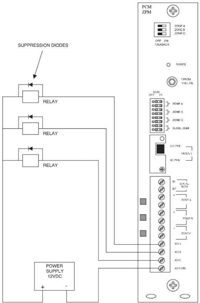
CONFIGURATION 15:
RELAY DRIVER OUTPUT
flowchart
graph TD
    A["SUPPRESSION DIODES"] --> B["RELAY"]
    B --> C["RELAY"]
    C --> D["RELAY"]
    D --> E["POWER SUPPLY 12VDC"]
    E --> F["PCM ZPM"]
    F --> G["OFF ON TALKBACK"]
    G --> H["POWER"]
    H --> I["1 PROM VOLL SIL"]
    I --> J["LO PWR OUTPUT"]
    J --> K["HE PWR"]
    K --> L["IN LOCAL RT Zone A Zone B Zone C Zone R Zone C Zone A Zone B Zone C Zone D"]
    L --> M["+"]
    M --> N["-"]
Each PCMZPM module has three relay driver outputs - RD A, RD B, and RD C - one for each speaker zone.
When a zone is activated, its relay driver is shorted to RD COM through an open collector transistor. These drivers can be used to activate external relays to provide greater power capacity or to operate external equipment. The power supply for these relays must be 12V DC or less. The total sink current per driver can not exceed 100mA.
SECTION II - PROGRAMMING
SYSTEM PROGRAMMING
System programming lets you set certain PCM options and tone features using the DTMF keys of a telephone. It also lets you program paging zone groups and signaling zone groups.
All programming is accomplished through the TRUNK/P/P jack on the PCMTIM module regardless of the telephone interface used.
Note: To simplify initial programming, it is recommended that you use the Loop Start Trunk configuration with a single-line 2500-series telephone or your Butt Set connected to the TRUNK/P/P input.
You do not need to program the system to set the zones. The system is ready from the factory to access individual zones and All-Call.
To program the PCM2000 system, follow these instructions:

- Remove the switch lock on the PCMCPU module and place the PROGRAM/RUN switch to the PROGRAM position (down). The green LED will illuminate.
- Access the PCM2000 system (either use a single 2500-line telephone or butt set or dial the paging access number from the telephone system).
- You will hear 3 beep tones indicating access to the programming mode.
- Dial the Feature Code for the option you wish to program. (See Feature Codes and Defaults list.)
Note: After you have entered a Feature Code (and any other data), you must press the [#] key to enter it into the system. If the system accepts the code (and data), you will hear a short double beep confirming that the data has been stored in the system.
Continue with the next Feature Code immediately after the confirming double beep.
If the information is not accepted, you will hear a busy tone. In this case, you should hang-up, check the code and the data, then re-access the system and try again.
- Once you have finished programming, you must first hang-up the programming phone and then place the Program/Run switch in the Run position. The green LED will go out. Replace the switch lock.
Remember to press the [#] key after you enter a Feature Code.
FEATURE CODES AND DEFAULTS
| Feature | Feature Code | Additional Data | Default |
| Privacy Beep | |||
| Inhibit | 006 | ||
| Enable | 007 | Enable | |
| Pre-announce Tone | |||
| Inhibit | 003 | ||
| Beep | 004 | ||
| Chime | 005 | Chime | |
| Confirmation Tone | |||
| Inhibit | 001 | Enable | |
| Enable | 002 | ||
| Emergency O/R Tone | |||
| Inhibit | 008 | Inhibit | |
| Enable | 009 | ||
| All-Call | |||
| Inhibit | 010 | ||
| Enable | 011 | Enable | |
| Dialing Time-out | |||
| Inhibit | 012 | ||
| Enable | 013 | Enable | |
| Trunk Disconnect | |||
| Inhibit | 014 | Inhibit | |
| Enable | 015 | ||
| 1 Amp BGM | |||
| Inhibit | 018 | Inhibit | |
| Enable | 019 | ||
| Default Timer | 050 | 00-99 | 03 (See Note 1 - p. 35) |
| VOX Timer | 051 | 0-9 | 6 (See Note 2 - p. 35) |
| Zone Group | *01 | Zones Numbers | No Zones |
| ↓ | " | ||
| " | |||
| " | |||
| *32 | " | ||
| EM/SC | |||
| Zone Group | *92 | Zone Numbers | All-Call |
| No Tone | 020 | ||
| Follow Contact | 021 | ||
| 2-Second Tone | 022 | ||
| 3-Second Tone | 023 | 3-Second Tone | |
| 4-Second Tone | 024 | ||
| 5-Second Tone | 025 | ||
| 6-Second Tone | 026 | ||
| 7-Second Tone | 027 | ||
| Chime | 028 | ||
| Quad Beep | 029 | ||
| Night Ring | |||
| Zone Group | *93 | Zone Numbers | All-Call |
| No Tone | 030 | ||
| Simulated Ring | 031 | Ring | |
| Chime | 032 | ||
| Code Call | |||
| Zone Group | *94 | Zone Numbers | All-Call |
| Inhibit | 040 | Inhibit | |
| Pattern | 041 | ||
| Echo | 042 | ||
| 1 Play | 043 | 1 Play | |
| 1 Repeat | 044 | ||
| 2 Repeat | 045 | ||
| Clock Set | 060 | HHMM | 00:00 |
| Clock Sync. | 067 | HHMM | (See Note 3 - p. 35) |
| Inhibit | 068 | Inhibit | |
| Enable | 069 | ||
| Time Trigger 1 | |||
| Zone Group | *81 | Zone Numbers | No Zones |
| Inhibit | 110 | Inhibit | |
| Enable | 111 | HHMM | (See Note 3 - p. 35) |
| 2-Second Tone | 112 | ||
| 3-Second Tone | 113 | 3-Second Tone | |
| 4-Second Tone | 114 | ||
| 5-Second Tone | 115 | ||
| 6-Second Tone | 116 | ||
| 7-Second Tone | 117 | ||
| 8-Second Tone | 118 | ||
| Chime | 119 | ||
| Time Trigger 2 | |||
| Zone Group | *82 | Zone Numbers | No Zones |
| Inhibit | 120 | Inhibit | |
| Enable | 121 | HHMM | (See Note 3 - p. 35) |
| 2-Second Tone | 122 | ||
| 3-Second Tone | 123 | 3-Second Tone | |
| 4-Second Tone | 124 | ||
| 5-Second Tone | 125 | ||
| 6-Second Tone | 126 | ||
| 7-Second Tone | 127 | ||
| 8-Second Tone | 128 | ||
| Chime | 129 | ||
| Time Trigger 3 | |||
| Zone Group | *83 | Zone Numbers | No Zones |
| Inhibit | 130 | Inhibit | |
| Enable | 131 | HHMM | (See Note 3 - p. 35) |
| 2-Second Tone | 132 | ||
| 3-Second Tone | 133 | 3-Second Tone | |
| 4-Second Tone | 134 | ||
| 5-Second Tone | 135 | ||
| 6-Second Tone | 136 | ||
| 7-Second Tone | 137 | ||
| 8-Second Tone | 138 | ||
| Chime | 139 | ||
| Time Trigger 4 | |||
| Zone Group | *84 | Zone Numbers | No Zones |
| Inhibit | 140 | Inhibit | |
| Enable | 141 | HHMM | (See Note 3 - p. 35) |
| 2-Second Tone | 142 | ||
| 3-Second Tone | 143 | 3-Second Tone | |
| 4-Second Tone | 144 | ||
| 5-Second Tone | 145 | ||
| 6-Second Tone | 146 | ||
| 7-Second Tone | 147 | ||
| 8-Second Tone | 148 | ||
| Time Trigger 5 | |||
| Zone Group | *85 | Zone Numbers | No Zones |
| Inhibit | 150 | Inhibit | |
| Enable | 151 | HHMM | (See Note 3 - p. 35) |
| 2-Second Tone | 152 | ||
| 3-Second Tone | 153 | 3-Second Tone | |
| 4-Second Tone | 154 | ||
| 5-Second Tone | 155 | ||
| 6-Second Tone | 156 | ||
| 7-Second Tone | 157 | ||
| 8-Second Tone | 158 | ||
| Chime | 159 | ||
| Time Trigger 6 | |||
| Zone Group | *86 | Zone Numbers | No Zones |
| Inhibit | 160 | Inhibit | |
| Enable | 161 | HHMM | (See Note 3 - below) |
| 2-Second Tone | 162 | ||
| 3-Second Tone | 163 | 3-Second Tone | |
| 4-Second Tone | 164 | ||
| 5-Second Tone | 165 | ||
| 6-Second Tone | 166 | ||
| 7-Second Tone | 167 | ||
| 8-Second Tone | 168 | ||
| Chime | 169 | ||
| Time Trigger 7 | |||
| Zone Group | *87 | Zone Numbers | No Zones |
| Inhibit | 170 | Inhibit | |
| Enable | 171 | HHMM | (See Note 3 - below) |
| 2-Second Tone | 172 | ||
| 3-Second Tone | 173 | 3-Second Tone | |
| 4-Second Tone | 174 | ||
| 5-Second Tone | 175 | ||
| 6-Second Tone | 176 | ||
| 7-Second Tone | 177 | ||
| 8-Second Tone | 178 | ||
| Chime | 179 | ||
| Time Trigger 8 | |||
| Zone Group | *88 | Zone Numbers | No Zones |
| Inhibit | 180 | Inhibit | |
| Enable | 181 | HHMM | (See Note 3 - below) |
| 2-Second Tone | 182 | ||
| 3-Second Tone | 183 | 3-Second Tone | |
| 4-Second Tone | 184 | ||
| 5-Second Tone | 185 | ||
| 6-Second Tone | 186 | ||
| 7-Second Tone | 187 | ||
| 8-Second Tone | 188 | ||
| Chime | 189 | ||
| Reset Default | 999 | ||
| Setup Tone(in Program Mode Only) | |||
| Turn On | 000 | ||
| Turn Off | Hang Up | ||
Notes to Feature Codes
Note 1- These 2 digits represent time in 10s of seconds, i.e., "01" = 10 seconds, "02" = 20 seconds, "03" = 30 seconds, etc. Entering "00" will inhibit timer operation
Note 2 - This single-digit indicates VOX delay time in seconds, i.e., "1" = 1 second, "2" = 2 seconds, etc. Entering "0" will inhibit VOX timer operation.
Note 3 - Entering the Feature Code without additional time data will enable feature using previously programmed time data.
SYS-ID SWITCH SETTINGS CHART FOR ADDITIONAL SATELLITE SYSTEMS
| Zone #'s | S1 | S2 | S3 | S4 | |
| Master | 1-9 | 0 | 0 | 0 | 0 |
| Satellite | |||||
| 1 | 10-18 | 1 | 0 | 0 | 0 |
| 2 | 19-27 | 0 | 1 | 0 | 0 |
| 3 | 28-36 | 1 | 1 | 0 | 0 |
| 4 | 37-45 | 0 | 0 | 1 | 0 |
| 5 | 46-54 | 1 | 0 | 1 | 0 |
| 6 | 55-63 | 0 | 1 | 1 | 0 |
| 7 | 64-72 | 1 | 1 | 1 | 0 |
| 8 | 73-81 | 0 | 0 | 0 | 1 |
| 9 | 82-90 | 1 | 0 | 0 | 1 |
| 10 | 91-99 | 0 | 1 | 0 | 1 |
APPENDIX

STEP 1: Assembling Modules PCMTIM to PCMCPU and to PCMZPM (see Illustration above)
- Plug the 6-pin power connector from the PCMCPU module to the PCMTIM module jack (J2). Be sure that the locking ridge faces header wall. (Green wire to the top.)
- Plug the 26-pin ribbon cable from the PCMCPU module to the PCMTIM module 26-pin connector (J1). Be sure to align the polarizing tab in slot. (Pin 1 red stripe to the top.)
- Place the modules together and dress the connector cables away from the sheet metal so they will not get pinched.
- Push the two units together while aligning the locking tabs in the PCMTIM module to the locking slots in the PCMCPU module. Slide the two units until the faces of both units are even.
- Secure the two units together by tightening a screw into the screw clamp tab in the back of the PCMTIM.
- Follow the same steps to add the PCMZPM module(s).
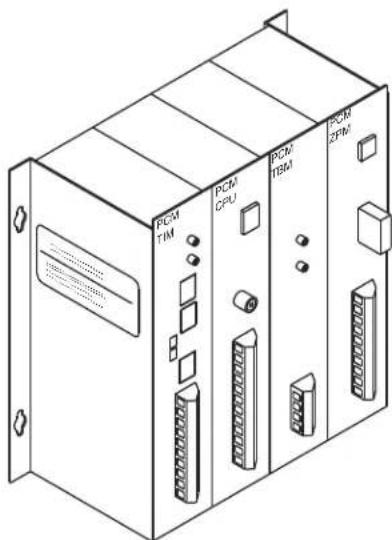
Completed Assembly
NOTE:
Modules must be assembled, left to right, in the order shown here: TIM, CPU, TBM (if necessary) and ZPM.
BOGEN®
COMMUNICATIONS, INC.
50 Spring Street, Ramsey, NJ 07446 U.S.A.
- SECTION I - APPLICATION CONFIGURATIONS ....4-31
- SECTION I: APPLICATION CONFIGURATIONS
- CONFIGURATION 1:
- PAGE PORT CONTACT CLOSURE / 3-ZONE / ONE-WAY PAGING / SINGLE AMPLIFIER / 25 & 70V AC SPEAKERS
- INSTALLATION:
- STEP 3: Switch Settings
- STEP 4: Testing your System
- STEP 5: Connecting the Paging Amplifier
- STEP 6: Connecting 25 & 70V AC Speakers
- STEP 7: Testing your System
- CONFIGURATION 2:
- PAGE PORT VOX CIRCUIT / 3-ZONE / ONE-WAY PAGING / SINGLE AMPLIFIER / 25 & 70V AC SPEAKERS
- CONFIGURATION 3:
- LOOP START TRUNK / 3-ZONE / ONE-WAY PAGING / SINGLE AMPLIFIER / 25 & 70V AC SPEAKERS
- CONFIGURATION 4:
- GROUND START TRUNK / 3-ZONE / ONE-WAY PAGING / SINGLE AMPLIFIER / 25 & 70V AC SPEAKERS
- CONFIGURATION 5:
- STATION LEVEL/CENTREX / 3-ZONE / ONE-WAY PAGING / SINGLE AMPLIFIER / 25 & 70V AC SPEAKERS
- CONFIGURATION 6:
- EXTENDED PAGING SYSTEM
- CONFIGURATION 7:
- TWO-WAY TALK BACK PAGING SYSTEM
- CONFIGURATION 8:
- TWO-WAY TALK BACK EXTENDED PAGING SYSTEM
- CONFIGURATION 9:
- 3-ZONE / ONE-WAY PAGING / LOW-POWER SYSTEM / SELF-AMPLIFIED SPEAKERS
- CONFIGURATION 11:
- MICROPHONE OVERRIDE
- STEP 2: Connecting the Paging Amplifier
- STEP 3: Connecting Optional Equipment
- STEP 4: Switch and Control Settings
- STEP 5: Testing Your System
- CONFIGURATION 12:
- DFT120 & TAMB2 WIRING DIAGRAM / GROUND START TRUNK OR STATION LEVEL
- STEP 1: Assemble Modules PCMTIM to PCMCPU and to PCMZPM (see Illustration/Instructions on Appendix page 37, then return to this page and complete the following Steps).
- STEP 3: Connecting an Analog Line or Ground Start Trunk from the Telephone System to the TAMB2
- STEP 4: Connecting the TAMB2 Module to the DFT120
- STEP 5: Connecting the DFT120 to the PCMTIM Module
- STEP 6: Switch and Control Settings
- CONFIGURATION 13:
- EMERGENCY ALERT TONES
- CONFIGURATION 14:
- STEP 1: Connecting Telephone System Paging Output to the PCMTIM
- STEP 2: Connecting the BGM Source
- STEP 3: PCMCPU Switch Settings
- STEP 4: Activating the Background Music
- STEP 5: Prepare System for Operation
- CONFIGURATION 15:
- RELAY DRIVER OUTPUT
- SECTION II - PROGRAMMING
- SYSTEM PROGRAMMING
- Notes to Feature Codes
- SYS-ID SWITCH SETTINGS CHART FOR ADDITIONAL SATELLITE SYSTEMS
- APPENDIX
- STEP 1: Assembling Modules PCMTIM to PCMCPU and to PCMZPM (see Illustration above)
- NOTE:
Brand : Bogen
Model : PCM2000
Category : Matériel électronique industriel