
FA2-1000.1 - Receiver MB QUART - Free user manual and instructions
Find the device manual for free FA2-1000.1 MB QUART in PDF.


| Product Type | Car Audio Monoblock Amplifier |
| Model | FA2-1000.1 |
| Brand | MB Quart |
| Power Output (RMS) | 1000W x 1 @ 1 Ohm, 500W x 1 @ 2 Ohm |
| Frequency Response | 10 Hz - 250 Hz |
| Input Sensitivity | 200 mV - 4V |
| Dimensions (L x W x H) | 10.2 x 6.3 x 2.1 inches (259 x 160 x 53 mm) |
| Weight | 3.2 lbs (1.45 kg) |
| Power Supply Voltage | 12V DC (10-16V) |
| Fuse Rating | 80A x 1 (ANL type) |
| Low Pass Filter | Variable 50 Hz - 250 Hz, 12 dB/octave |
| Subsonic Filter | Fixed 25 Hz, 12 dB/octave |
| Bass Boost | 0-12 dB at 45 Hz |
| Inputs | RCA x 1 pair (line level), speaker level inputs |
| Outputs | Binding posts (up to 8 AWG) |
| Protection Circuits | Thermal, over-current, DC offset, short circuit |
| Remote Turn-On | 12V trigger wire |
| Cooling | Convection + internal fan |
| Construction | Aluminum heatsink, painted steel chassis |
| Mounting | M4 screws (not included) |
| Certifications | CE, RoHS |
| Maintenance | Keep vents clear; wipe with dry cloth; no moisture |
| Spare Parts | Contact MB Quart customer service |
| Included Accessories | Mounting screws, user manual, remote bass knob (optional) |
Frequently Asked Questions - FA2-1000.1 MB QUART
User questions about FA2-1000.1 MB QUART
0 question about this device. Answer the ones you know or ask your own.
Ask a new question about this device
Download the instructions for your Receiver in PDF format for free! Find your manual FA2-1000.1 - MB QUART and take your electronic device back in hand. On this page are published all the documents necessary for the use of your device. FA2-1000.1 by MB QUART.
USER MANUAL FA2-1000.1 MB QUART
Many new and factory radios require a reset code when disconnected from battery power. This is an anti-theft feature. Before unplugging power, you must determine if your radio/source unit requires a reset code. Check the operation manual for your vehicle or contact the dealer.
Power cable size and fusing
Model
Fuse Size
Cable Size
It is critical to use the proper power and ground cable. Select the size listed here for your amplifier model. Always use high quality copper cable. Visit our website for multi amp system cable recommendations.
Be sure to use the proper fuse size for each model.
FA2-400.4
External 40A
FA2-900.5
External 100A
FA2-1000.1
External 80A
FA 2-1500.1
External 100A
FA2-2000.1

Installation

Disconnect
negative battery
terminal
Place terminal in a secure position so that it won't accidentally contact the negative battery post


Run Cables
Properly route power, speaker and RCA cables through the vehicle.


Mount Amplifier
Choose a mounting location that will provide adequate air ventilation. Mount the amplifier to a secure surface. Do not mount the amplifier upside down.


Chassis Ground

The chassis ground connection is critical to the performance of the amplifier. Choose a location that is close to the amplifier. Completely scrape away the paint and use a nut and bolt if possible. DO NOT USE AN EXISTING FACTORY BOLT!

natural_image
Technical line drawing of two mechanical components with bolts and a nut (no text or symbols)
Negative Power Connection
Attach the chassis ground cable to the amplifier negative terminal. It is important to make sure this connection is very tight.


Remote Turn-on Connection
Attach the remote turn on wire to the amplifier remote output of the source unit.


Positive Power Connection
Attach the main power cable to the amplifier +12V. The cable must run directly to
the battery and be properly fused and be very tight.


Signal Input Connection
Connect the RCA cables to the coordinating RCA input number that will match the speaker outputs number.


Turn on Mode
REM turn on (Remote wire turn on) when using High Level Input - DC turn on
- Signal Sense turn on
Auto-Sense Technical Guide
回:


NOTE - If the RCA's are plugged into the amplifier and the TURN ON MODE is in the DC ON position, the amplifier will NOT turn on. Please re-read QR document above or hire a professional installer.

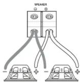
Speaker Connections
Using spade terminals, connect the speaker cables to the speaker output connectors. Follow the
diagram below that best fits your speaker configuration.

Stereo

Bridged
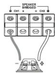

onoblock single woofer
onoblock multiple woofers


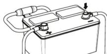
Positive Battery Connection
Connect the power cable to the positive battery terminal. The power cable must be fused within 18 inches of the battery terminal.


Be prepared to disarm your vehicle's alarm and to enter your radio / source unit code.


Re-connect Negative Battery Terminal
Re-connect the negative battery terminal making sure it is securely tightened.
Setup Common System Setup
| A | 2CH-Input CH1/CH2Output CH1/CH2/CH3/CH4 (FA2-400.4)Output CH1/CH2/CH3/CH4/CH5 (FA2-900.5) 4CH-Input CH1/CH2/CH3/CH4Output CH1/CH2/CH3/CH4 (FA2-400.4)Output CH1/CH2/CH3/CH4/CH5 (FA2-900.5) 5CH-Input CH1/CH2/CH3/CH4/CH5Output CH1/CH2/CH3/CH4/CH5 (FA2-900.5) | INPUT MODE | INPUT MODE | |
| 2CH | 4CH | |||
| B | The Crossover Mode switch sets the type of crossover that will be active. 4 channel models will have two switches, one for each set of channels. | X-OVER | ||
| HPF | LPF | FULL | ||
| C | The HPF(high pass iter) control will limit the output below the selected frequency. This is typically used to protect midrange and hi frequency speakers from damage and to allow a smooth transition from a subwoofer. | HPF | SUBSINIC | |
| 40Hz | 400Hz | 18Hz | ||
| D | The LPF(low pass iter) control will limit output above the selected frequency. This is used to allow a smooth transition to the higher frequency speakers. | 40Hz | 400Hz | |
| E | The Bass Boost control will increase the power output at 45Hz for more pronounced bass. Exercise caution when using this control. Increase the level in small amounts until distortion is noticed, then back off a little. | BASS BOOST | ||
| 6dB | +12dB | |||
| F | Some models include a bass remote. Avoid adjusting the bass remote while operating vehicle. | |||
| G | This is a critical step to insure your amplifier is properly adjusted to match the signal output level of your source unit. | LEVEL | ||
| THIS IS NOT A VOLUME CONTROL! | 12v | 0.2v | ||
-
If possible, with the source unit off, con rm that the primary volume control is turned down (counter clockwise).
-
Turn on the source unit (CD, or MP3 player). Re-con rm that the volume is turned down. Make sure the source unit controls; balance, fader, bass and treble are all set to center or "0" adjustment. Make sure that the green LED on
The information contained within this document is intended to offer some basic guidelines
for a few of the most common installations. More complex audio systems should be installed by a competent professional. Additional installation information available at
www.maxxsonics.com
WARRANTY
Maxxsonics, LLC. warrants this product, to the original consumer purchaser, to be free from defense in material and workmanship for a period of one (1) year from the date of purchase
Quick Start
Installation Guide
FA2-400.4
FA2-900.5
FA2-1000.1
FA2-1500.1
FA2-2000.1

- Power cable size and fusing
- Installation
- Disconnect
- Run Cables
- Mount Amplifier
- Chassis Ground
- Negative Power Connection
- Remote Turn-on Connection
- Positive Power Connection
- Signal Input Connection
- Turn on Mode
- Auto-Sense Technical Guide
- Speaker Connections
- onoblock single woofer
- onoblock multiple woofers
- Positive Battery Connection
- Be prepared to disarm your vehicle's alarm and to enter your radio / source unit code.
- Re-connect Negative Battery Terminal
Brand : MB QUART
Model : FA2-1000.1
Category : Receiver