MX4EC1 - Generator Mr Steam - Free user manual and instructions
Find the device manual for free MX4EC1 Mr Steam in PDF.


| Product Type | Steam Generator |
| Model | MX4EC1 (MAX Series) |
| Dimensions (H x W x D) | 27-5/8 x 20-3/4 x 7-7/8 inches |
| Power Rating | 20 kW |
| Voltage | 240 V, Single Phase |
| Amperage | 84 A |
| Wire Size (AWG) | 2 (90°C THHN copper) |
| Water Usage (per 20 min) | 2.7 gallons |
| Steam Room Capacity | 676 - 875 cubic feet |
| Control Options | iSteam3, iTempo, iTempo/Plus, AirTempo |
| Drain Type | Gravity drain via 1/2" NPT valve |
| Water Feed | Cold water line, shut-off valve, union |
| AutoFlush System | Integrated, flushes tank automatically |
| Safety Features | Safety valve, liquid level control, over-temp protection |
| Accessories | AromaSteam, ChromaSteam3, AudioSteam3, speakers, shower seat |
| Installation Requirements | Near steam room, 30 ft control cable included, conduit for cable |
| Warranty | Refer to full manual (estimated 5 years for tank) |
Frequently Asked Questions - MX4EC1 Mr Steam
User questions about MX4EC1 Mr Steam
0 question about this device. Answer the ones you know or ask your own.
Ask a new question about this device
Download the instructions for your Generator in PDF format for free! Find your manual MX4EC1 - Mr Steam and take your electronic device back in hand. On this page are published all the documents necessary for the use of your device. MX4EC1 by Mr Steam.
USER MANUAL MX4EC1 Mr Steam
QUICK SET UP GUIDE
GENERATOR | CONTROLS | ACCESSORIES
mr.steam®
Feel Good Inc.

natural_image
Modern bathroom interior with marble shower chamber and white marble walls, featuring a decorative lamp and vase (no text or symbols visible)
natural_image
Interior view of a modern bathroom with marble partition, glass pendant light, and patterned wall (no text or symbols)CONTENTS
GENERATOR LOCATION 5
POWER CONNECTION 6
WATER FEED 7
STEAM OUTLET 7
DRAIN LINE 7
AUTOFLUSH ^® 8
CONDENSATION PAN 9
LIQUID LEVEL CONTROL BOARD 9
MAX GENERATOR INSTALLATION 10
GENERATOR 11
MOUNT INSTALLATION 20
iTEMPO® OR ITEMPO/PLUS® CONTROL
INSTALLATION 23
REMOTE TEMPERATURE PROBE
INSTALLATION 24
CONTROL CABLE TO THE STEAM GENERATOR
CONNECTION 26
⚠ WARNING As you follow these instructions, you will notice warning and caution symbols. This blocked information is important for the safe and efficient installation and operation of this generator. These are types of potential hazards that may occur during installation and operation:
△WARNING Indicates a potentially hazardous situation, which, if not avoided, could result in death or serious injury.
△CAUTION Indicates a potentially hazardous situation, which, if not avoided may result in minor or moderate injury or product damage.
IMPORTANT NOTE: This highlights information that is especially relevant to a problem-free installation.
All information in these instructions is based on the latest product information available at the time of publication. Sussman-Automatic Corporation reserves the right to make changes at any time without notice. More current instructions may be available at www.mrsteam.com.
⚠ WARNING The information in this guide is designed to provide a general overview of how MrSteam® products are installed. All images and diagrams are for illustrative purposes only and may have been altered for presentation purposes. NEVER use this document for the Installation, Operation or Maintenance of any MrSteam® product. For installation, operation and maintenance information and instructions, only use the applicable MrSteam® Installation, Operation & Maintenance Manual(s). The specific Installation, Operation & Maintenance manual that is supplied with each MrSteam® product contains important information required for the safe and reliable installation and operation of the product. Failure to install any MrSteam® product according to the applicable manual may result in property damage, an inoperable system/control, or hazardous condition. If you do not have the applicable Installation, Operation & Maintenance manual please contact MrSteam® for a free copy, or download a copy from www.mrsteam.com. If you have any questions about the installation, operation or maintenance of any MrSteam® product please contact a customer or technical service representative using the contact information on the back cover of this guide or consult a properly licensed contractor, architect and/or design professional.
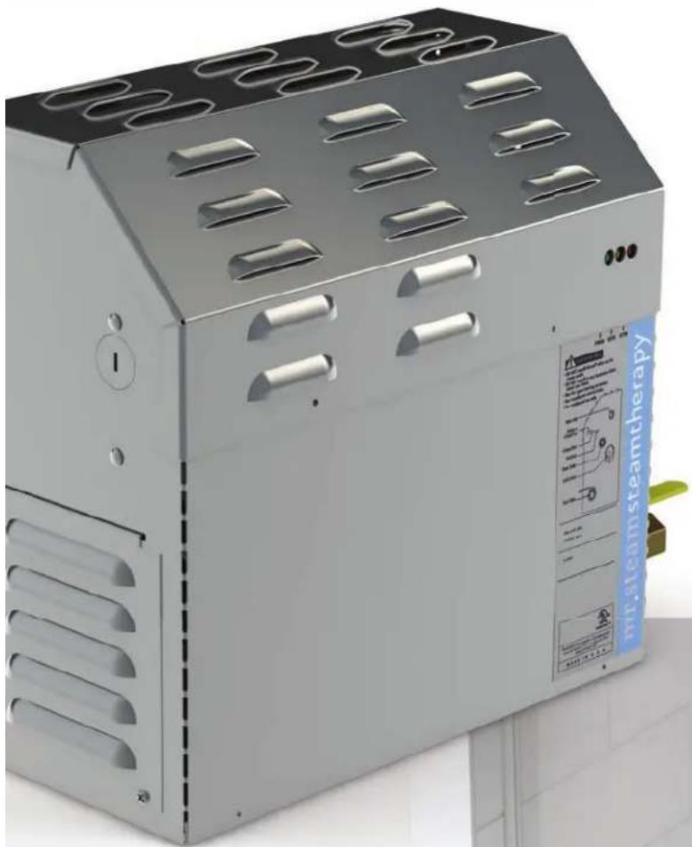
MR.STEAM®
GENERATOR INSTALLATION
LOCATING THE MR.STEAM® GENERATOR
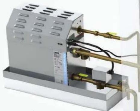
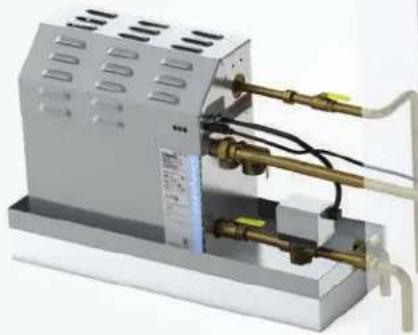
Select a location as near as practical to the steam room. Typical locations include: closet, vanity cabinet, climate controlled attic or basement.
natural_image
3D rendering of a mechanical device with pipes and housing (no visible text or symbols)Locate steambath generator as close to shower as possible. 30ft cable is included. Optional 60ft cable available
WARNING The information in this guide is designed to provide a general overview of how MrSteam® products are installed. All images and diagrams are for illustrative purposes only and may have been altered for presentation purposes. NEVER use this document for the Installation, Operation or Maintenance of any MrSteam® product. For installation, operation and maintenance information and instructions, only use the applicable MrSteam® Installation, Operation & Maintenance Manual(s). The specific Installation, Operation & Maintenance manual that is supplied with each MrSteam® product contains important information required for the safe and reliable installation and operation of the product. Failure to install any MrSteam® product according to the applicable manual may result in property damage or an inoperable or hazardous condition. If you do not have the applicable Installation, Operation & Maintenance manual please contact MrSteam® for a free copy, or download a copy from www.mrsteam.com. If you have any questions about the installation, operation or maintenance of any MrSteam® product please contact a customer or technical service representative using the contact information on the back cover of this guide or consult a properly licensed contractor, architect and/or design professional.
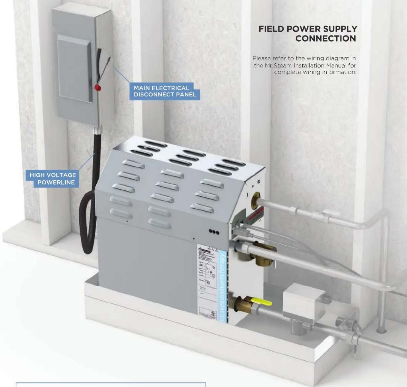
TO AVOID EQUIPMENT DAMAGE DO NOT CONNECT POWER SUPPLY DIRECTLY TO THE HEATING ELEMENTS!!!
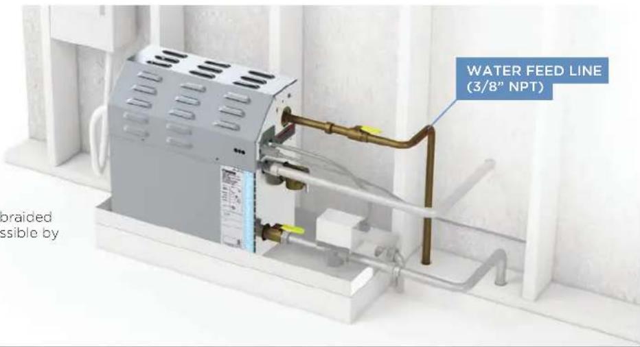
WATER FEED
- Connect to cold water line.
- Provide a shut off valve, and a copper or brass union on the water supply line.
- Flexible copper tubing, braided hose, PVC or PEX if permissible by local codes.
STEAM OUTLET PIPE
- Provide a 1/2" copper or brass union on steam line.
- Pitch steam line 1/4" per foot towards steam head or steam generator to avoid valleys and trapping of condensate.
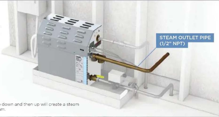
NOTE: Running the steam line down and then up will create a steam trap blocking the flow of steam.
MANUAL DRAIN LINE
- Drain (1/2" NPT).
- Unit drains by gravity.
- Provide 1/2" copper or brass union.
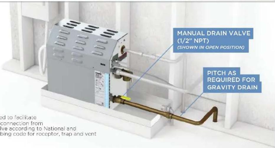
NOTE: A drain valve is provided to facilitate servicing. Provide a drain line connection from steambath generator drain valve according to National and local Codes. Check local plumbing code for receptor, trap and vent requirements.
WARNING The information in this guide is designed to provide a general overview of how MrSteam® products are installed. All images and diagrams are for illustrative purposes only and may have been altered for presentation purposes. NEVER use this document for the Installation, Operation or Maintenance of any MrSteam® product. For installation, operation and maintenance information and instructions, only use the applicable MrSteam® Installation, Operation & Maintenance Manual(s). The specific Installation, Operation & Maintenance manual that is supplied with each MrSteam® product contains important information required for the safe and reliable installation and operation of the product. Failure to install any MrSteam® product according to the applicable manual may result in property damage or an inoperable or hazardous condition. If you do not have the applicable Installation, Operation & Maintenance manual please contact MrSteam® for a free copy, or download a copy from www.mrsteam.com. If you have any questions about the installation, operation or maintenance of any MrSteam® product please contact a customer or technical service representative using the contact information on the back cover of this guide or consult a properly licensed contractor, architect and/or design professional.
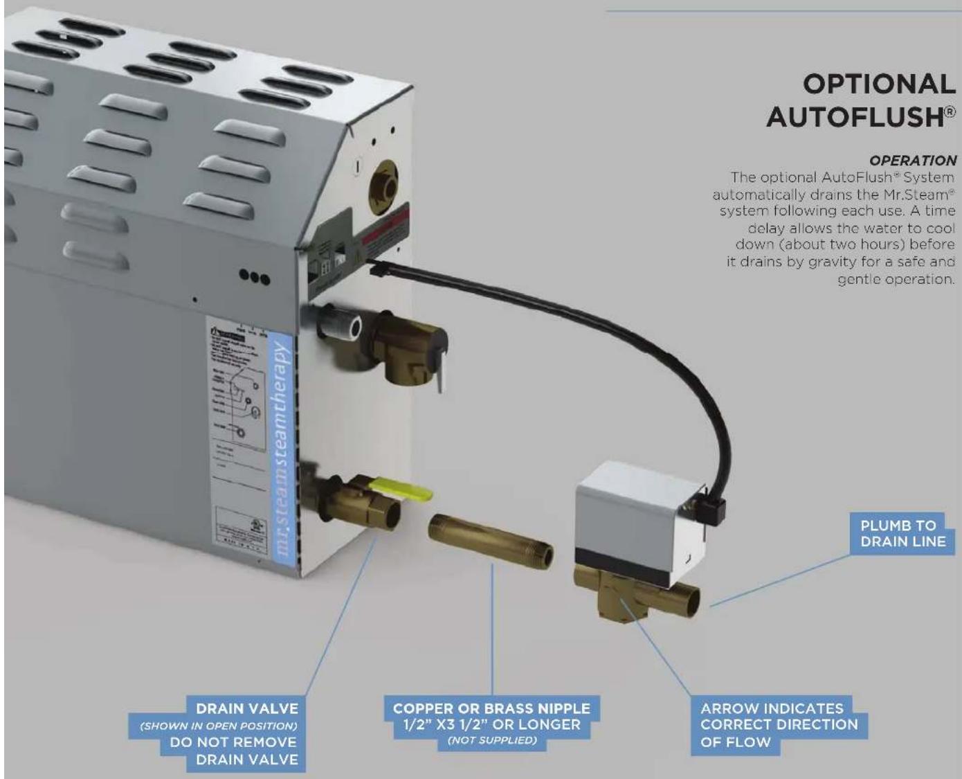

CAUTION: PROVIDE DRAIN PLUMBING ACCORDING TO NATIONAL AND LOCAL CODES. PLUMB AS REQUIRED FOR AUTOFLUSH® SYSTEM.
WARNING The information in this guide is designed to provide a general overview of how MrSteam® products are installed. All images and diagrams are for illustrative purposes only and may have been altered for presentation purposes. NEVER use this document for the Installation, Operation or Maintenance of any MrSteam® product. For installation, operation and maintenance information and instructions, only use the applicable MrSteam® installation, Operation & Maintenance Manual(s). The specific Installation, Operation & Maintenance manual that is supplied with each MrSteam® product contains important information required for the safe and reliable installation and operation of the product. Failure to install any MrSteam® product according to the applicable manual may result in property damage or an inoperable or hazardous condition. If you do not have the applicable Installation, Operation & Maintenance manual please contact MrSteam® for a free copy, or download a copy from www.mrsteam.com. If you have any questions about the installation, operation or maintenance of any MrSteam® product please contact a customer or technical service representative using the contact information on the back cover of this guide or consult a properly licensed contractor, architect and/or design professional.
CONDENSATION PAN
DO NOT PLUMB THE GENERATOR DRAIN AND CONDENSATION PAN DRAIN TOGETHER
GENERATOR DRAIN
CONDENSATION PAN
3/4" OUTLET
TO BE PLUMBED SEPARATELY
LIQUID LEVEL
CONTROL BOARD
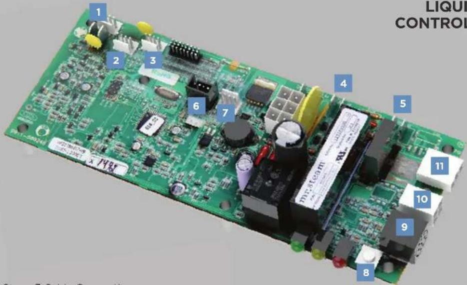
1 ChromaSteam3 Cable Connection
2 SteamLinx A Cable Connection
3 AudioSteam3 Cable Connection
4 AromaSteam 1/4" Spade Terminal Connection
5 Chroma72 1/4" Space Terminal Connection
6 MSTS (Remote Temperature Sensor) Connection
7 Tandem Connection (for two generators)
8 Test Button
9 Control Cable Connection
10 Home Wizard Connection
11 AutoFlush Connection
NEW
MAX STEAM GENERATOR INSTALLATION
(MX 4E, 5E & 6E)
DO NOT INSTALL IN VANITY OR OTHER SMALL SPACES
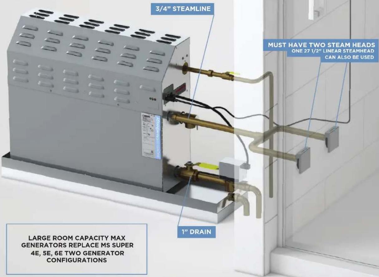
Refer to the Mr.Steam MAX Installation
manual for additional installation information.
WARNING The information in this guide is designed to provide a general overview of how MrSteam® products are installed. All images and diagrams are for illustrative purposes only and may have been altered for presentation purposes. NEVER use this document for the Installation, Operation or Maintenance of any MrSteam® product. For installation, operation and maintenance information and instructions, only use the applicable MrSteam® Installation, Operation & Maintenance Manual(s). The specific Installation, Operation & Maintenance manual that is supplied with each MrSteam® product contains important information required for the safe and reliable installation and operation of the product. Failure to install any MrSteam® product according to the applicable manual may result in property damage or an inoperable or hazardous condition. If you do not have the applicable Installation, Operation & Maintenance manual please contact MrSteam® for a free copy, or download a copy from www.mrsteam.com. If you have any questions about the installation, operation or maintenance of any MrSteam® product please contact a customer or technical service representative using the contact information on the back cover of this guide or consult a properly licensed contractor, architect and/or design professional.
MRSTEAM ^® GUIDE
TYPICAL MS GENERATOR
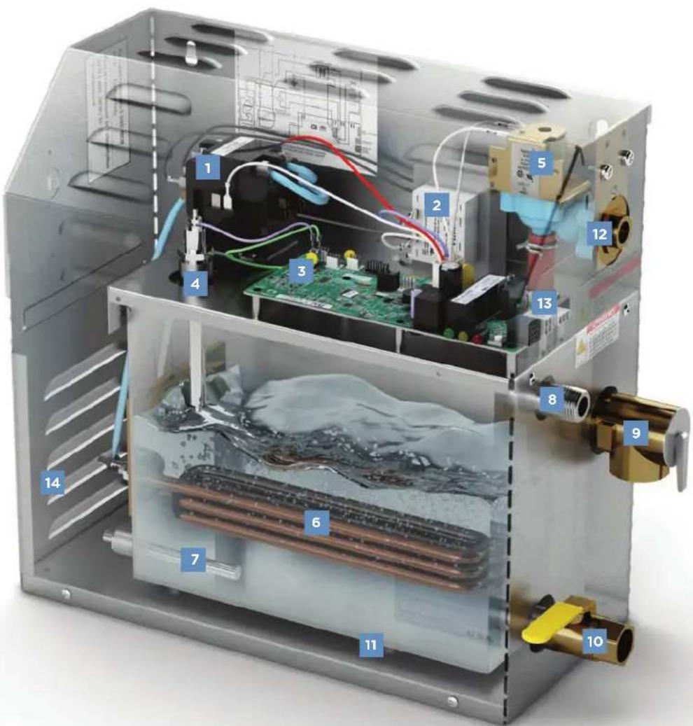
1 Contactor
2 Transformer
3 Liquid Level Control Board
4 Liquid Level Probe
5 Water Feed Solenoid
6 Heating Element
7 Express Steam Heater (optional)
8 Steam Outlet
9 Safety Valve
10 Drain Valve
11 Stainless Steel Tank
12 Water Inlet
13 Plug & Play Connection
14 Element Access Cover
| Product Dimensions* Model No. | Total Room Volume (cu.ft.) | kW | Amps 240V/1PH | Wire Size AWG‡ | Water Usage Gallons" |
MS Generators
14 1/2" x 14 3/4" x 6 3/4"
MS90E up to 100 5 21 10 0.67
MS150 101-150 6 25 8 0.80
MS225E 151-225 7.5 32 81.0
MS400E 226-360 9 38 8 1.2

SUPER Generators 17" x 18 1/2" x 7 7/8"
| MSSUPER1E 361-475 10 42 | 8 1.4 | ||||
| MSSUPER2E | 476-575 | 12 | 50 | 6 | 1.6 |
| MSSUPER3E | 576-675 | 15 | 63 | 4 | 2.0 |
NEW
MAX Generators
27 5/8" x 20 3/4" x 7 7/8"
| MX4E | 676-875 | 20 | 84 | 2 | 2.7 |
| MX5E | 876-1075 | 24 | 100 | 1 | 3.2 |
| MX6E | 1076-1275 | 30 | 125 | 2/0 | 4.0 |
* Dimensions are for generator only, without AutoFlush® or plumbing features.
1 Wire size (AWG) based on minimum 90 rated THHN copper conductors. Refer to the National Electrical Code for other types of conductors.
^+ Water usage based on 20 minutes of operation.
FOR ADDITIONAL INFORMATION ON CONTROLS AND ACCESSORIES SEE CORRESPONDING QUICK GUIDES
WARNING The information in this guide is designed to provide a general overview of how MrSteam® products are installed. All images and diagrams are for illustrative purposes only and may have been altered for presentation purposes. NEVER use this document for the Installation, Operation or Maintenance of any MrSteam® product. For installation, operation and maintenance information and instructions, only use the applicable MrSteam® Installation, Operation & Maintenance Manual(s). The specific Installation, Operation & Maintenance manual that is supplied with each MrSteam® product contains important information required for the safe and reliable installation and operation of the product. Failure to install any MrSteam® product according to the applicable manual may result in property damage or an inoperable or hazardous condition. If you do not have the applicable Installation, Operation & Maintenance manual please contact MrSteam® for a free copy, or download a copy from www.mrsteam.com. If you have any questions about the installation, operation or maintenance of any MrSteam® product please contact a customer or technical service representative using the contact information on the back cover of this guide or consult a properly licensed contractor, architect and/or design professional.
natural_image
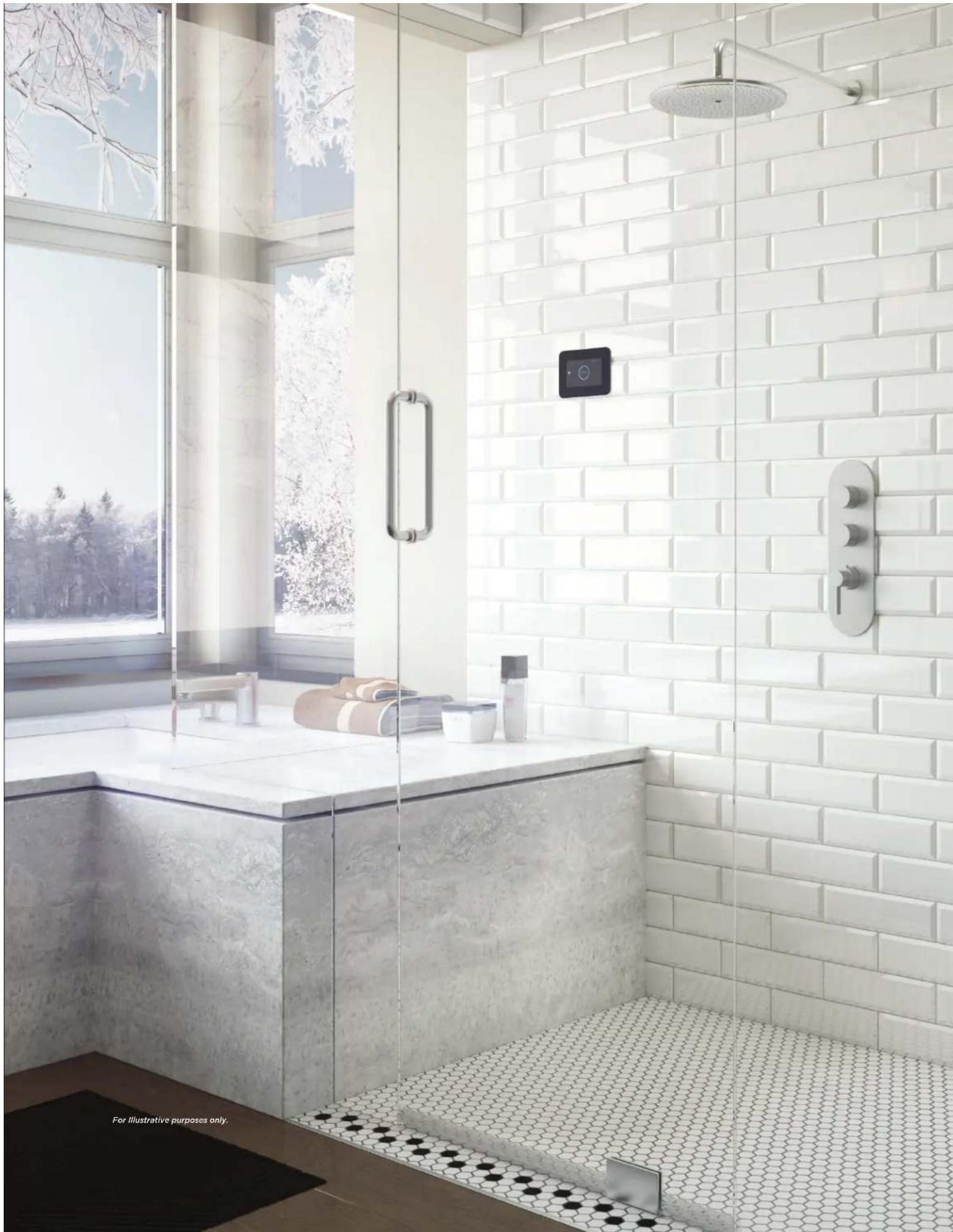
Modern bathroom interior with white brick shower, glass partition, and digital shower unit (no text or symbols visible)LOCATING THE iSTEAM®3, iTEMPO®, iTEMPO/PLUS® & AIRTEMPO® CONTROLS
RUN CABLE THROUGH CONDUIT INSIDE WALL CAVITY.
CABLE NOT REQUIRED WITH AIRTEMPO ^10 .
natural_image
3D rendering of a mechanical device with multiple pipes and a control panel (no visible text or symbols)Locate control (or Remote Temperature Sensor) where it will sense general room temperature and NOT direct steam emission from the steam head.
Controls installed inside the steam room must be located 4-5 feet above the floor on a vertical wall.
Locating any control outside of the steam room will require the installation of a Remote Temperature Sensor inside the steam room (see page 13).
CAUTION: TO AVOID UNINTENTIONAL STEAM BATH OPERATION, DO NOT LOCATE THE CONTROL WHERE OTHER CONTROLS, ACCESSORIES, SHOWER HEADS, VALVES, BODY SPRAYS OR SIMILAR WITHIN THE SHOWER COULD CAUSE CONFUSION OR INTERFERE WITH THE MRSTEAM CONTROL'S INTENDED USE AND FUNCTION.

iSTEAM®3
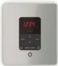
ITEMPO/PLUS®

natural_image
Digital kitchen control panel with digital display and control buttons (no readable text or symbols)AIRTEMPO®
WARNING The information in this guide is designed to provide a general overview of how MrSteam® products are installed. All images and diagrams are for illustrative purposes only and may have been altered for presentation purposes. NEVER use this document for the Installation, Operation or Maintenance of any MrSteam® product. For installation, operation and maintenance information and instructions, only use the applicable MrSteam® Installation, Operation & Maintenance Manual(s). The specific Installation, Operation & Maintenance manual that is supplied with each MrSteam® product contains important information required for the safe and reliable installation and operation of the product. Failure to install any MrSteam® product according to the applicable manual may result in property damage, an inoperable system/control, or hazardous condition. If you do not have the applicable Installation, Operation & Maintenance manual please contact MrSteam® for a free copy, or download a copy from www.mrsteam.com. If you have any questions about the installation, operation or maintenance of any MrSteam® product please contact a customer or technical service representative using the contact information on the back cover of this guide or consult a properly licensed contractor, architect and/or design professional.
IMPORTANT NOTE: To avoid unintentional steam bath operation, do not locate the control where other controls, accessories, shower heads, valves, body sprays or similar within the shower could cause confusion or interfere with the MrSteam control's intended use and function.
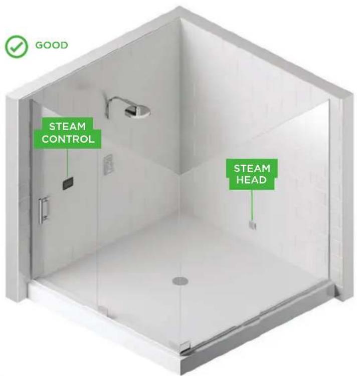
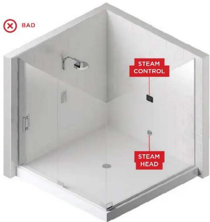
DO NOT LOCATE THE CONTROL ABOVE OR NEAR THE STEAM HEAD OR DIRECT STEAM EMISSIONS
WARNING The information in this guide is designed to provide a general overview of how MrSteam® products are installed. All images and diagrams are for illustrative purposes only and may have been altered for presentation purposes. NEVER use this document for the Installation, Operation or Maintenance of any MrSteam® product. For installation, operation and maintenance information and instructions, only use the applicable MrSteam® Installation, Operation & Maintenance Manual(s). The specific Installation, Operation & Maintenance manual that is supplied with each MrSteam® product contains important information required for the safe and reliable installation and operation of the product. Failure to install any MrSteam® product according to the applicable manual may result in property damage, an inoperable system/control, or hazardous condition. If you do not have the applicable Installation, Operation & Maintenance manual please contact MrSteam® for a free copy, or download a copy from www.mrsteam.com. If you have any questions about the installation, operation or maintenance of any MrSteam® product please contact a customer or technical service representative using the contact information on the back cover of this guide or consult a properly licensed contractor, architect and/or design professional.
iSTEAM®3 CONTROL INSTALLATION
IMPORTANT NOTE: Turn power to the steam generator OFF before installing the control. Failure to turn the power off will result in an inoperable control.
STEP 1
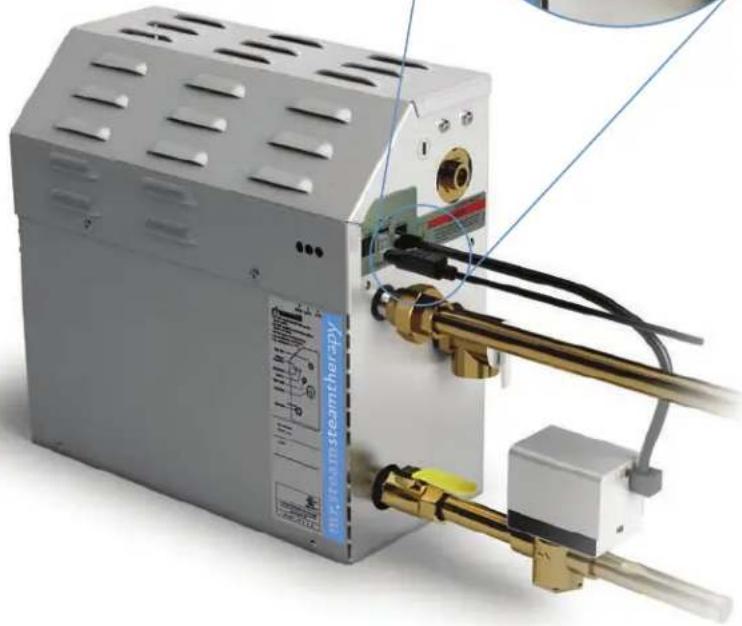
PLUG the 30' control cable into the iSteam®3 control pigtail (1A). Turn the generator on and test the control to verify proper function.
Install rough-in box in desired control location.
Use rough-in box provided as a guide to cut hole in finished wall.
natural_image
Close-up of a white industrial power supply unit with brass fittings and tubing, no visible text or symbols on the main body.CAUTION: DO NOT FORCE OR TWIST CABLE CONNECTOR INTO THE RECEPTACLE. FORCING OR TWISTING MAY DAMAGE THE CONNECTORS.
WARNING The information in this guide is designed to provide a general overview of how MrSteam® products are installed. All images and diagrams are for illustrative purposes only and may have been altered for presentation purposes. NEVER use this document for the Installation, Operation or Maintenance of any MrSteam® product. For installation, operation and maintenance information and instructions, only use the applicable MrSteam® Installation, Operation & Maintenance Manual(s). The specific Installation, Operation & Maintenance manual that is supplied with each MrSteam® product contains important information required for the safe and reliable installation and operation of the product. Failure to install any MrSteam® product according to the applicable manual may result in property damage, an inoperable system/control, or hazardous condition. If you do not have the applicable Installation, Operation & Maintenance manual please contact MrSteam® for a free copy, or download a copy from www.mrsteam.com. If you have any questions about the installation, operation or maintenance of any MrSteam® product please contact a customer or technical service representative using the contact information on the back cover of this guide or consult a properly licensed contractor, architect and/or design professional.
2A
natural_image
3D rendering of a gray rectangular device with a white connector and beige base, no visible text or symbols on the body.STEP 2
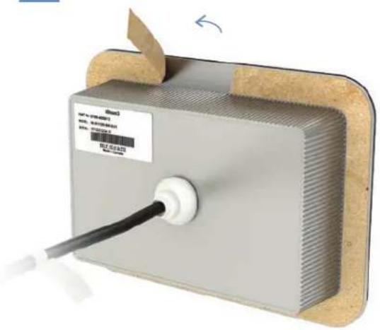
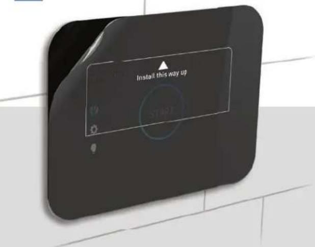
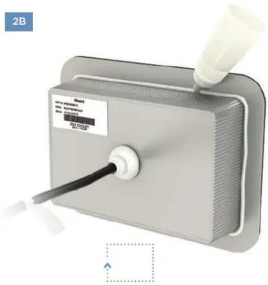
Peel the adhesive film off the back of the iSteam control (2A). Apply a bead of silicone (provided) around the rear of the control as required to create a moisture seal (2B).
Ensure the control is level. Carefully feed the cable into the rough-in box and secure the control to the wall. Care must be taken to not pinch the cable.
Remove and discard the peel off screen protector (2C).
2C
natural_image
3D rendering of a handheld electronic device with a white tube inserted, labeled '2B' in the corner (no readable text or symbols on the device itself)WARNING The information in this guide is designed to provide a general overview of how MrSteam® products are installed. All images and diagrams are for illustrative purposes only and may have been altered for presentation purposes. NEVER use this document for the Installation, Operation or Maintenance of any MrSteam® product. For installation, operation and maintenance information and instructions, only use the applicable MrSteam® installation, Operation & Maintenance Manual(s). The specific Installation, Operation & Maintenance manual that is supplied with each MrSteam® product contains important information required for the safe and reliable installation and operation of the product. Failure to install any MrSteam® product according to the applicable manual may result in property damage, an inoperable system/control, or hazardous condition. If you do not have the applicable Installation, Operation & Maintenance manual please contact MrSteam® for a free copy, or download a copy from www.mrsteam.com. If you have any questions about the installation, operation or maintenance of any MrSteam® product please contact a customer or technical service representative using the contact information on the back cover of this guide or consult a properly licensed contractor, architect and/or design professional.
AIRTEMPO® SURFACE MOUNT INSTALLATION

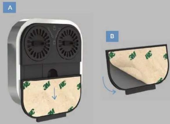
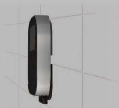
STEP 1 Determine the desired installation location of the control. The AirTempo controls are designed to be installed inside or outside the steam room as a matter of personal preference.
- Remove the surface mount bayonet from the back of the AirTempo Control (A).
- Remove and discard the release paper to expose the adhesive liner (B).
STEP 2
STEP 3
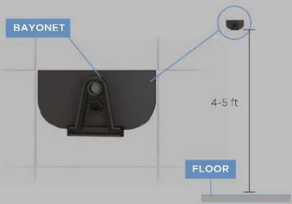
- Ensure the mounting surface is clean, flat/smooth, and dry.
- Place the bayonet on the wall in the desired location (on vertical wall 4-5 feet above the floor near the bather seating area).
natural_image
3D rendered image of a metallic cylindrical object with a black end, mounted on a grid background (no text or symbols)STEP 4 - Wait 15 minutes before placing the control on the bayonet to ensure the adhesive is secured.
IMPORTANT NOTE: If the control is installed outside the steam room, a Remote Temperature Probe (part number MSTS) must be installed inside the steam room. See Remote Temperature Sensor page 12.
Use the screw and anchor provided to secure the bayonet to the wall as required for rough or uneven wall surfaces. The surface mount bayonet supports the weight of the AirTempo® control.
WARNING The information in this guide is designed to provide a general overview of how MrSteam® products are installed. All images and diagrams are for illustrative purposes only and may have been altered for presentation purposes. NEVER use this document for the Installation, Operation or Maintenance of any MrSteam® product. For installation, operation and maintenance information and instructions, only use the applicable MrSteam® Installation, Operation & Maintenance Manual(s). The specific Installation, Operation & Maintenance manual that is supplied with each MrSteam® product contains important information required for the safe and reliable installation and operation of the product. Failure to install any MrSteam® product according to the applicable manual may result in property damage, an inoperable system/control, or hazardous condition. If you do not have the applicable Installation, Operation & Maintenance manual please contact MrSteam® for a free copy, or download a copy from www.mrsteam.com. If you have any questions about the installation, operation or maintenance of any MrSteam® product please contact a customer or technical service representative using the contact information on the back cover of this guide or consult a properly licensed contractor, architect and/or design professional.
AIRTEMPO® WIRELESS RECEIVER INSTALLATION
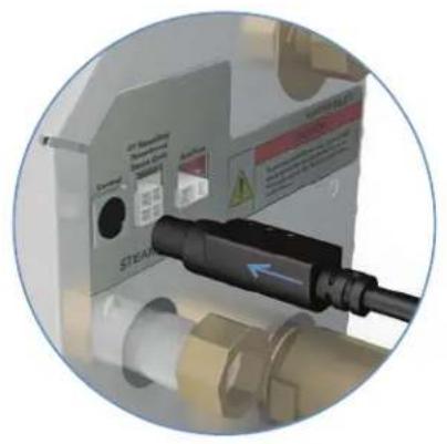
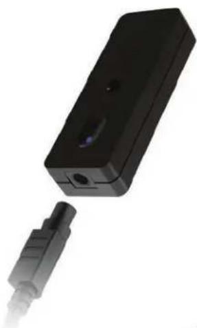
The control can be located up to 60 feet from the wireless receiver. Construction materials may affect the communication between the control and the receiver. Test the range of the AirTempo ^® . It may be necessary to change the location of the wireless receiver to improve the range. Contact your local MrSteam ^® representative (https://www.mrsteam.com/fi nd-a-dealer) for an optional 30 or 60 foot cable. Using the 3 foot cable provided, plug one end into the steam bath generator and the other end into the AirTempo ^® wireless receiver.
natural_image
Two black electronic devices, one with ports and one connected to a cable (no visible text or symbols)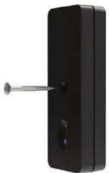
natural_image
Black rectangular device with a metallic screw and two ports, isolated on white background (no text or symbols)Attach the wireless receiver to a wall adjacent to the steam generator using the screw provided.
AIRTEMPO® FLUSH MOUNT INSTALLATION
STEP 1
Remove the surface mount bayonet from the back of the AirTempo ^3 control. The surface mount bayonet is not used when flush mounting.
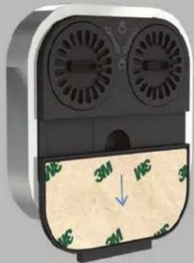
natural_image
3D rendering of a device with two fans and a textured surface, showing no readable text or symbols.
IMPORTANT NOTE: Flush mount components are sold separately (104232RD & 104232SQ). Contact a MrSteam® representative if a flush mount kit is needed.
WARNING The information in this guide is designed to provide a general overview of how MrSteam® products are installed. All images and diagrams are for illustrative purposes only and may have been altered for presentation purposes. NEVER use this document for the Installation, Operation or Maintenance of any MrSteam® product. For installation, operation and maintenance information and instructions, only use the applicable MrSteam® Installation, Operation & Maintenance Manual(s). The specific Installation, Operation & Maintenance manual that is supplied with each MrSteam® product contains important information required for the safe and reliable installation and operation of the product. Failure to install any MrSteam® product according to the applicable manual may result in: property damage, an inoperable system/control, or hazardous condition. If you do not have the applicable Installation, Operation & Maintenance manual please contact MrSteam® for a free copy, or download a copy from www.mrsteam.com. If you have any questions about the installation, operation or maintenance of any MrSteam® product please contact a customer or technical service representative using the contact information on the back cover of this guide or consult a properly licensed contractor, architect and/or design professional.
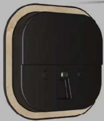
natural_image
3D rendered image of a black wall-mounted device with beige frame and black buttons (no text or symbols)
natural_image
Simple 3D-rendered gray cube with rounded corners (no text or symbols)STEP 2
Remove decorative bezel from AirTempo® control.
IMPORTANT NOTE: BE CAREFUL NOT TO DROP CONTROLLER WHEN RING POPS OFF
STEP 3
- Using the template provided, cut the hole in the desired location. Do not oversize or undersize the cutout. Ensure the template is level before cutting the hole.
- Test fill the flush mount box to ensure the hole is the correct size.
- Ensure the mounting surface is clean and dry.
STEP 4
Apply a bead of silicone (provided) around the rear of the control as required to create a moisture seal.
Remove and discard the release paper to expose the adhesive liner.
Press the flush mount box against the wall until the adhesive sticks and holds firmly.

natural_image
Close-up of a black rectangular electronic device with a metallic clip and two circular buttons (no visible text or symbols)WARNING The information in this guide is designed to provide a general overview of how MrSteam® products are installed. All images and diagrams are for illustrative purposes only and may have been altered for presentation purposes. NEVER use this document for the Installation, Operation or Maintenance of any MrSteam® product. For installation, operation and maintenance information and instructions, only use the applicable MrSteam® installation, Operation & Maintenance Manual(s). The specific Installation, Operation & Maintenance manual that is supplied with each MrSteam® product contains important information required for the safe and reliable installation and operation of the product. Failure to install any MrSteam® product according to the applicable manual may result in property damage, an inoperable system/control, or hazardous condition. If you do not have the applicable Installation, Operation & Maintenance manual please contact MrSteam® for a free copy, or download a copy from www.mrsteam.com. If you have any questions about the installation, operation or maintenance of any MrSteam® product please contact a customer or technical service representative using the contact information on the back cover of this guide or consult a properly licensed contractor, architect and/or design professional.
STEP 5
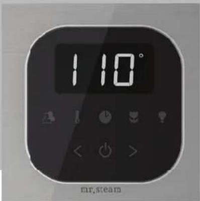
Place the electronic assembly into the decorative bezel as shown.
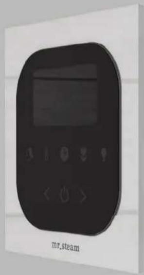
natural_image
Black remote control device with digital display and control buttons, labeled 'mr.steam' below (no other text or symbols)
natural_image
Black rounded rectangular object with a small protrusion on the left side (no text or symbols visible)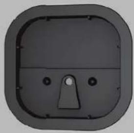
natural_image
3D rendering of a dark rectangular mechanical component with a central slot and mounting holes (no text or symbols)STEP 6
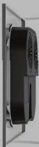
The retention ring snaps onto the assembly from behind. The 3 piece assembly can then be placed into the flush mount box.
natural_image
Close-up of a black industrial fan or vent unit mounted on a white panel (no visible text or symbols)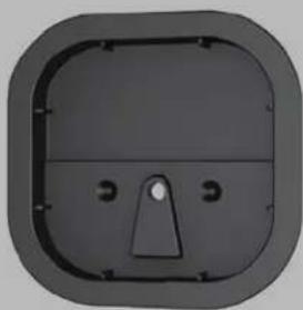
natural_image
3D rendered image of a square-shaped mechanical component with internal features (no text or symbols)WARNING The information in this guide is designed to provide a general overview of how MrSteam® products are installed. All images and diagrams are for illustrative purposes only and may have been altered for presentation purposes. NEVER use this document for the Installation, Operation or Maintenance of any MrSteam® product. For installation, operation and maintenance information and instructions, only use the applicable MrSteam® Installation, Operation & Maintenance Manual(s). The specific Installation, Operation & Maintenance manual that is supplied with each MrSteam® product contains important information required for the safe and reliable installation and operation of the product. Failure to install any MrSteam® product according to the applicable manual may result in property damage, an inoperable system/control, or hazardous condition. If you do not have the applicable Installation, Operation & Maintenance manual please contact MrSteam® for a free copy, or download a copy from www.mrsteam.com. If you have any questions about the installation, operation or maintenance of any MrSteam® product please contact a customer or technical service representative using the contact information on the back cover of this guide or consult a properly licensed contractor, architect and/or design professional.
iTEMPO OR iTEMPO/PLUS CONTROL INSTALLATION
IMPORTANT NOTE: Turn power to the steam generator OFF before installing the control. Failure to turn the power off will result in an inoperable control.
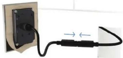
natural_image
Close-up of a black cable with two connectors connected to a wall-mounted socket (no text or symbols visible)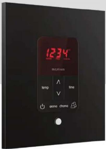
STEP 1
Firmly connect the control cable to the control pigtail. Turn on power to the steam generator and test the control to verify correct connections. Test per instructions.
Disconnect control cable. Make a 2-5/8" wide by 3-7/8" high cutout in the desired control location.
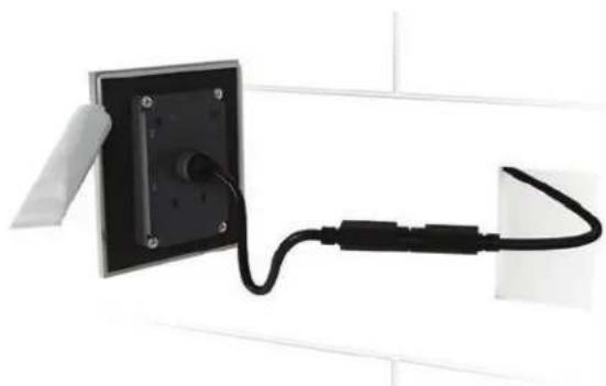
natural_image
Close-up of a black cable with a connector attached to a wall-mounted panel (no text or symbols visible)STEP 2
Firmly connect control cable. Remove & discard peel-off paper to expose adhesive liner.
STEP 3
Apply a bead of silicone (provided) around the rear of the control as required to create a moisture seal.

natural_image
Close-up of a black electronic device with control buttons and a circular button, no visible text or symbols.STEP 4
Ensure the mounting surface is clean, flat/smooth, and dry as required for good adhesion. Hold the control with the LED display in the 12 o'clock position and press the control against the wall until the adhesive sticks and holds firmly as shown.
REMOTE TEMPERATURE SENSOR (MSTS)
A Remote Temperature Sensor is required when the control is installed outside the steam room.
Locate the Remote Temperature Sensor where it will sense general room temperature and NOT direct steam emission from the steam head. Refer to the MrSteam Installation manual for additional control installation information.
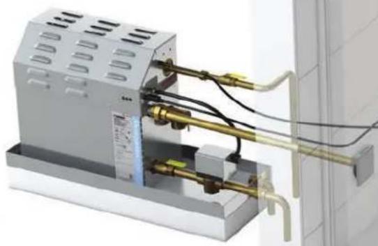
natural_image
3D rendering of a mechanical device with brass fittings and tubing, no visible text or symbolsFor Illustrative purposes only. Consult with qualified designer, architect or contractor for steamroom construction details.
MRSTEAM® GUIDE
INSTALLING A REMOTE TEMPERATURE PROBE
STEP 1
The Probe must be installed:
A. On a vertical surface
B. 4-5 feet above the Floor
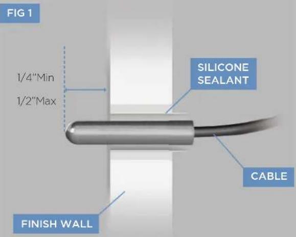
C. In a location representative of the desired steambathing temperatures. Do not locate the probe above or near the steam head or direct steam emissions. The probe has an integral 30 or 60 ft. cable. Ensure that the probe and control are located accordingly.
STEP 2
Drill a 5/16 inch hole in the wall. Do not oversize or undersize the hole. Clean area thoroughly.
STEP 3
Route the end of the temperature probe cable with the temperature probe through a conduit inside the wall cavity as shown in Fig 1.
WARNING The information in this guide is designed to provide a general overview of how MrSteam® products are installed. All images and diagrams are for illustrative purposes only and may have been altered for presentation purposes. NEVER use this document for the Installation, Operation or Maintenance of any MrSteam® product. For installation, operation and maintenance information and instructions, only use the applicable MrSteam® Installation, Operation & Maintenance Manual(s). The specific Installation, Operation & Maintenance manual that is supplied with each MrSteam® product contains important information required for the safe and reliable installation and operation of the product. Failure to install any MrSteam® product according to the applicable manual may result in property damage, an inoperable system/control, or hazardous condition. If you do not have the applicable Installation, Operation & Maintenance manual please contact MrSteam® for a free copy, or download a copy from www.mrsteam.com. If you have any questions about the installation, operation or maintenance of any MrSteam® product please contact a customer or technical service representative using the contact information on the back cover of this guide or consult a properly licensed contractor, architect and/or design professional.
STEP 4
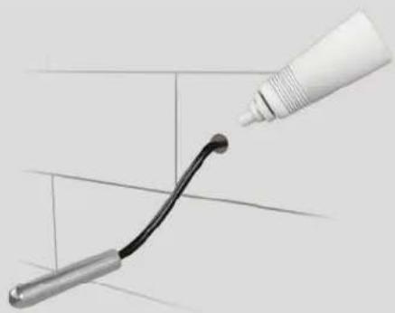
With a minimal length of the cable exposed, apply silicone (provided) to the hole in the wall as required to create a moisture seal as shown in Fig 2.
FIG 2
natural_image
3D illustration of a pipe being inserted into a curved black pipe, with no visible text or symbolsSTEP 5
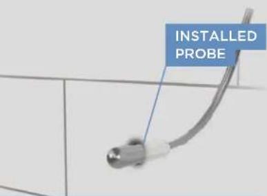
Push the Remote Temperature Probe into hole as required to leave between 1/4"-1/2" of the probe. Exposed as shown in Fig 3.
STEP 6
Ensure a minimum of 1/4" of the probe is exposed to the air. Failure to do so may result in an inoperative control and a hazardous condition. The exposed area of the probe must be free of silicone or any materials that prevent direct exposure to the steam room air. Failure to do so may interfere with the ability to sense temperature and may result in excessive steam room temperatures.
FIG 3
IMPORTANT NOTE: DO NOT STRAIN, STAPLE, PINCH OR OTHERWISE DAMAGE THE PROBE CABLE.
STEP 7
Plug MSTS into location shown on PC board (EXT. TEMP)
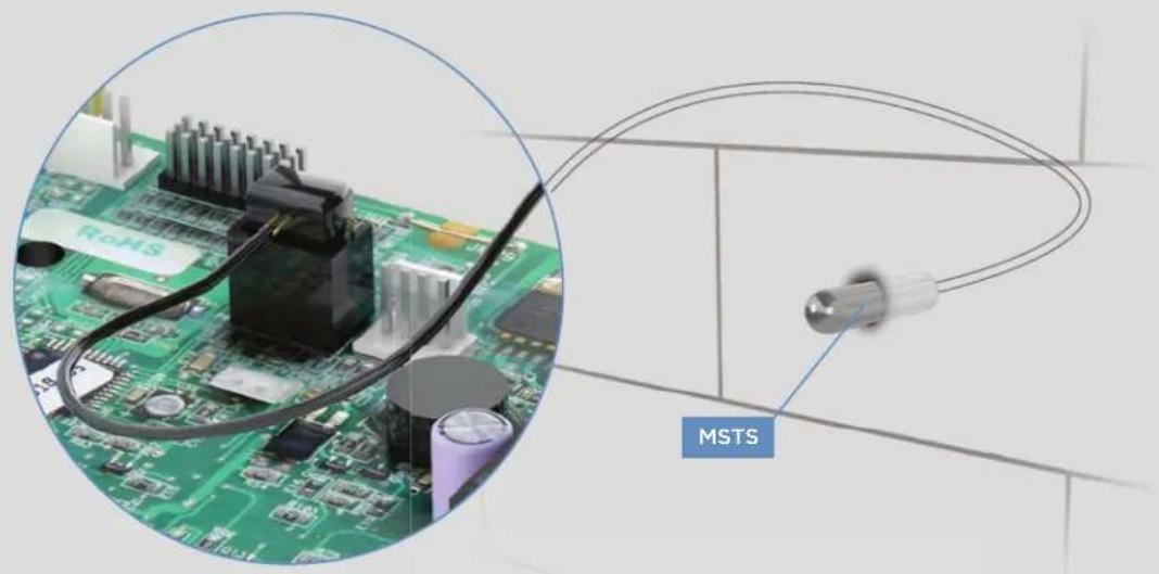
natural_image
Close-up of a green printed circuit board with attached components, showing a close-up inset of a microcontroller and a labeled sensor (MSTS) connected by wires.WARNING The information in this guide is designed to provide a general overview of how MrSteam® products are installed. All images and diagrams are for illustrative purposes only and may have been altered for presentation purposes. NEVER use this document for the Installation, Operation or Maintenance of any MrSteam® product. For installation, operation and maintenance information and instructions, only use the applicable MrSteam® Installation, Operation & Maintenance Manual(s). The specific Installation, Operation & Maintenance manual that is supplied with each MrSteam® product contains important information required for the safe and reliable installation and operation of the product. Failure to install any MrSteam® product according to the applicable manual may result in property damage, an inoperable system/control, or hazardous condition. If you do not have the applicable Installation, Operation & Maintenance manual please contact MrSteam® for a free copy, or download a copy from www.mrsteam.com. If you have any questions about the installation, operation or maintenance of any MrSteam® product please contact a customer or technical service representative using the contact information on the back cover of this guide or consult a properly licensed contractor, architect and/or design professional.
CONNECTING THE CONTROL CABLE TO THE STEAM GENERATOR
Route the control cable (provided with the control) from the wall cutout to the steam generator. The 30' (and optional 60') control cable features identical Mini-Din connectors at both ends.
IMPORTANT NOTE: The standard length of the cable for connecting the control to the steam generator is 30 feet. The steam generator and control must be located accordingly. Contact a MrSteam® representative (https://www.mrsteam.com/fi nd-a-dealer) to purchase an optional 60 ft. cable (PN 103990-60) for iTempo® controls. A 60 foot cable is available for use with iSteam® 3 controls (PN 104117-60).
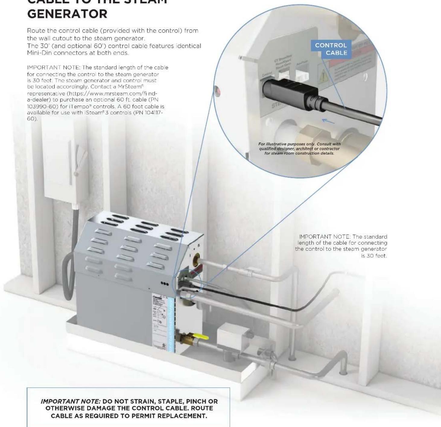
IMPORTANT NOTE: DO NOT STRAIN, STAPLE, PINCH OR OTHERWISE DAMAGE THE CONTROL CABLE. ROUTE CABLE AS REQUIRED TO PERMIT REPLACEMENT.
WARNING The information in this guide is designed to provide a general overview of how MrSteam® products are installed. All images and diagrams are for illustrative purposes only and may have been altered for presentation purposes. NEVER use this document for the Installation, Operation or Maintenance of any MrSteam® product. For installation, operation and maintenance information and instructions, only use the applicable MrSteam® Installation, Operation & Maintenance Manual(s). The specific Installation, Operation & Maintenance manual that is supplied with each MrSteam® product contains important information required for the safe and reliable installation and operation of the product. Failure to install any MrSteam® product according to the applicable manual may result in property damage, an inoperable system/control, or hazardous condition. If you do not have the applicable Installation, Operation & Maintenance manual please contact MrSteam® for a free copy, or download a copy from www.mrsteam.com. If you have any questions about the installation, operation or maintenance of any MrSteam® product please contact a customer or technical service representative using the contact information on the back cover of this guide or consult a properly licensed contractor, architect and/or design professional.

natural_image
Interior view of a modern bathroom with glass partition, brick walls, and shower shower (no text or symbols visible)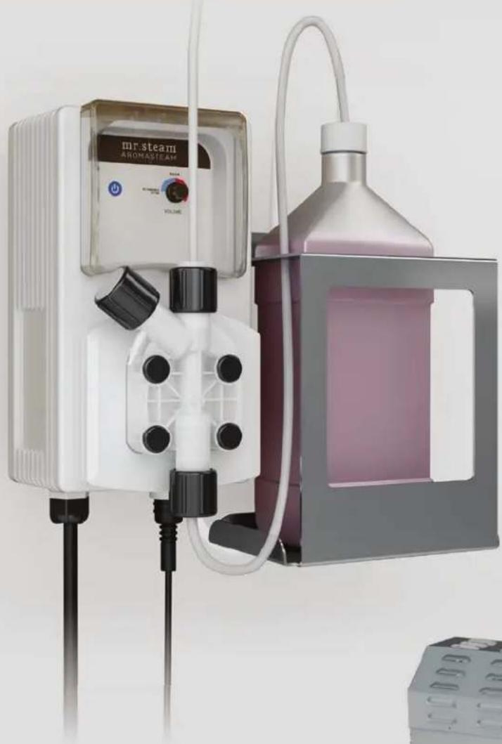
natural_image
Laboratory setup with MR steam ARONASTEAM device and pink liquid container (no visible text or symbols)AROMASTEAM SYSTEM
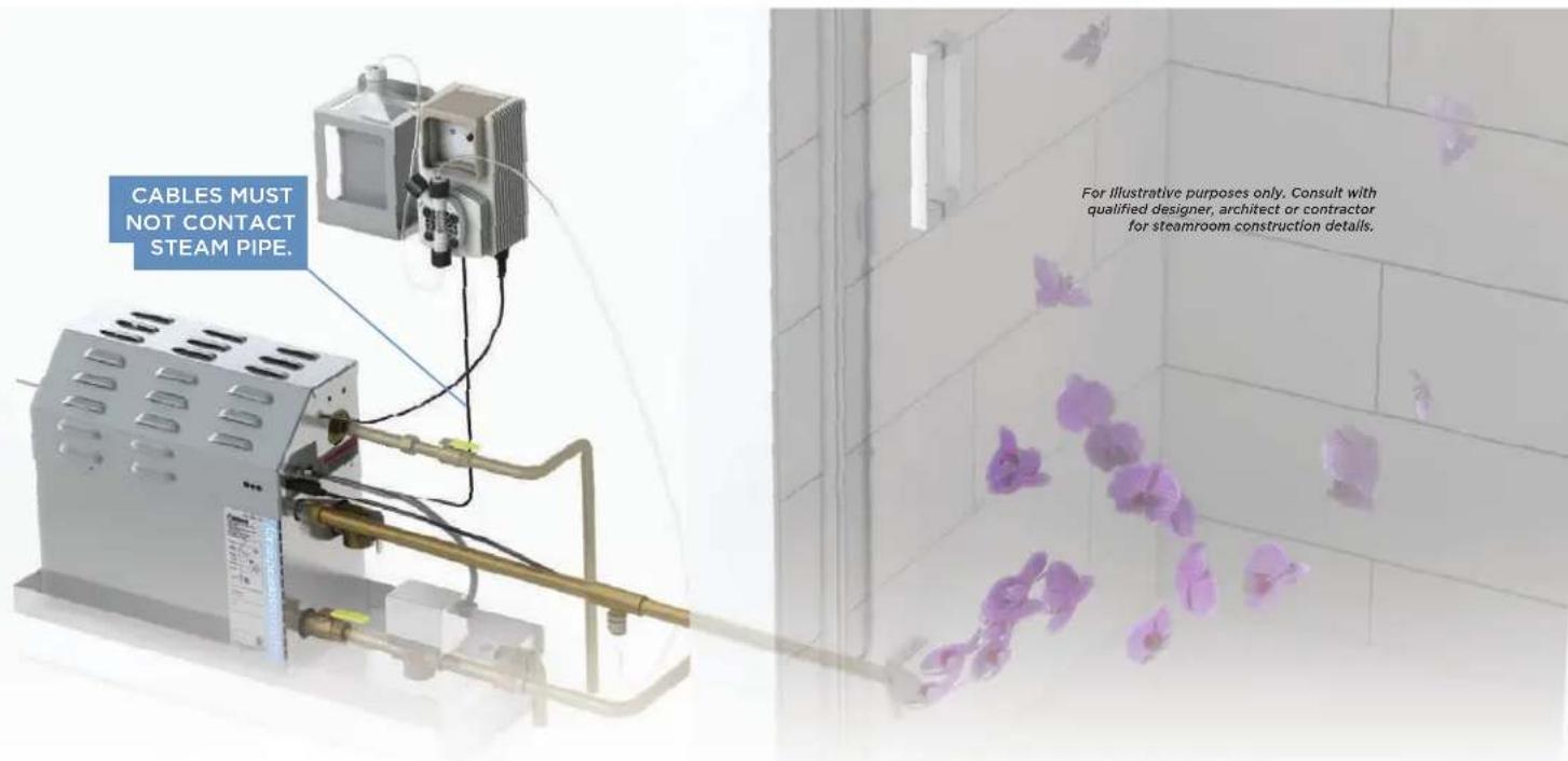
Electronic Oil delivery system evenly infuses aroma into steam for an aromatherapy experience. Complete with oil container caddy, hoses, fittings and oil check valve.
AromaSteam Essential oils are available in one-liter bottles. Not for use with acrylic or fi berglass rooms.
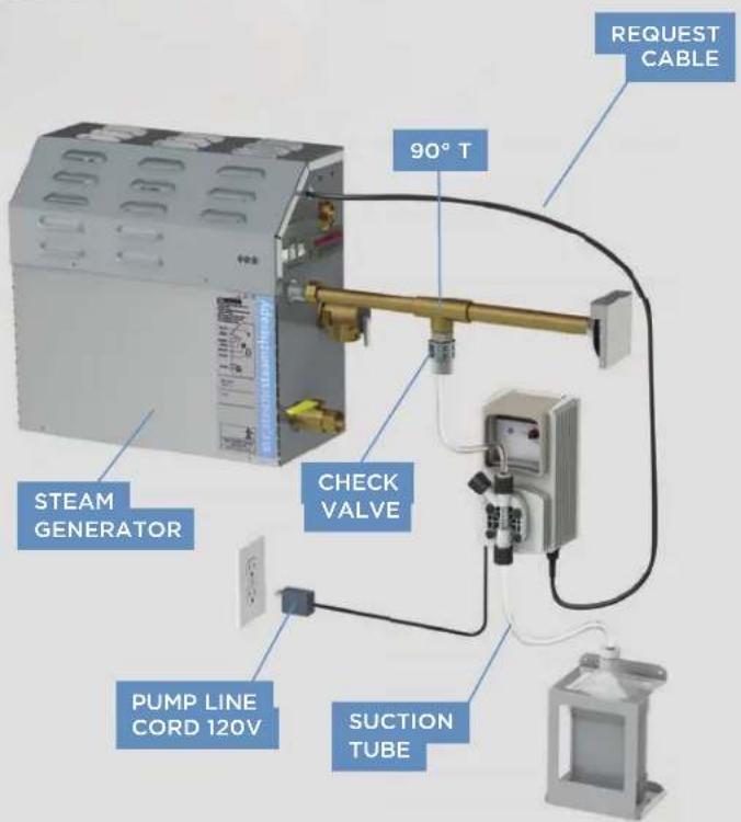
DO NOT EXCEED 30 FEET OF TUBING OR A VERTICAL DISTANCE OF 6 FEET BETWEEN THE PUMP HEAD AND CHECK VALVE.
STEP 1
Install the AromaSteam in a location convenient for replacing essential oil bottles.
STEP 2
Install the Check valve into a tee in the steamline.
STEP 3
Connect the preassembled pressure tube to the AromaSteam pump and the check valve.
STEP 4
Connect the preassembled suction tube to the AromaSteam pump and place the end into the essential oil bottle. Place the essential oil bottle into the caddy provided.
WARNING The information in this guide is designed to provide a general overview of how MrSteam® products are installed. All images and diagrams are for illustrative purposes only and may have been altered for presentation purposes. NEVER use this document for the Installation, Operation or Maintenance of any MrSteam® product. For installation, operation and maintenance information and instructions, only use the applicable MrSteam® Installation, Operation & Maintenance Manual(s). The specific Installation, Operation & Maintenance manual that is supplied with each MrSteam® product contains important information required for the safe and reliable installation and operation of the product. Failure to install any MrSteam® product according to the applicable manual may result in property damage, an inoperable system/control, or hazardous condition. If you do not have the applicable Installation, Operation & Maintenance manual please contact MrSteam® for a free copy, or download a copy from www.mrsteam.com. If you have any questions about the installation, operation or maintenance of any MrSteam® product please contact a customer or technical service representative using the contact information on the back cover of this guide or consult a properly licensed contractor, architect and/or design professional.
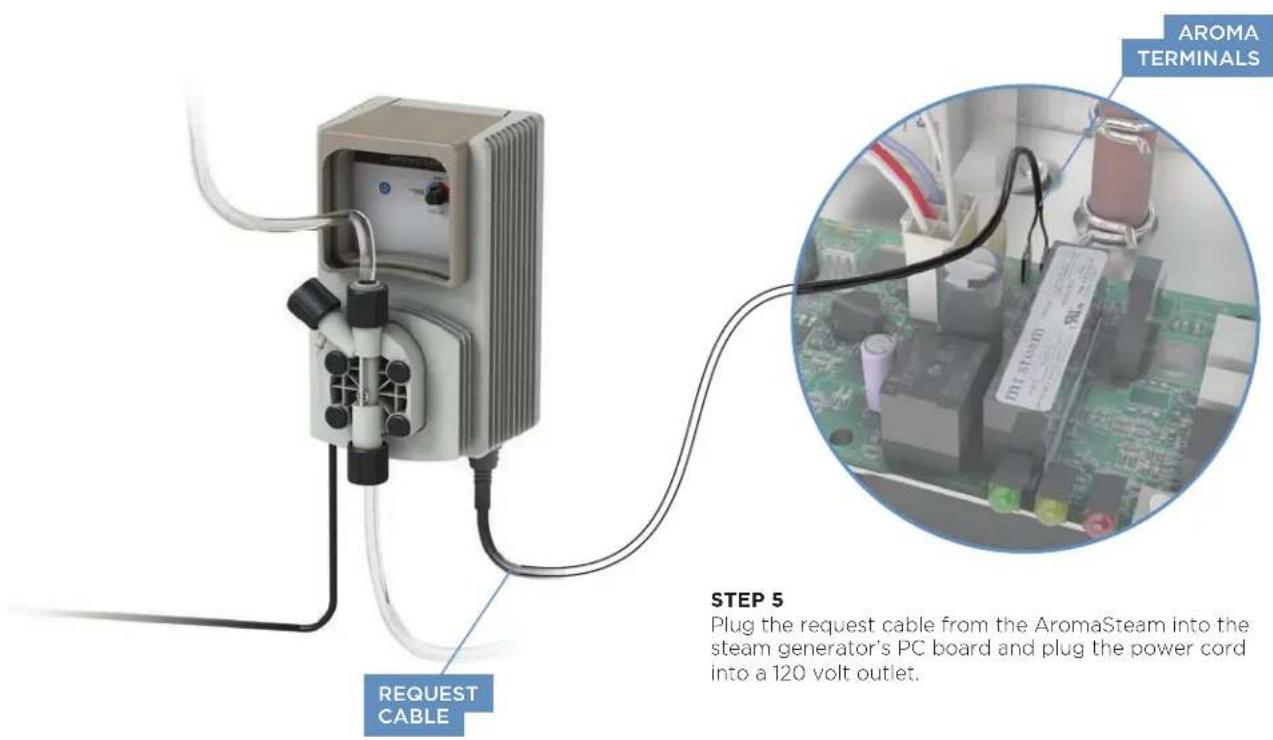
Plug the request cable from the AromaSteam into the steam generator's PC board and plug the power cord into a 120 volt outlet.
WARNING The information in this guide is designed to provide a general overview of how MrSteam® products are installed. All images and diagrams are for illustrative purposes only and may have been altered for presentation purposes. NEVER use this document for the Installation, Operation or Maintenance of any MrSteam® product. For installation, operation and maintenance information and instructions, only use the applicable MrSteam® Installation, Operation & Maintenance Manual(s). The specific Installation, Operation & Maintenance manual that is supplied with each MrSteam® product contains important information required for the safe and reliable installation and operation of the product. Failure to install any MrSteam® product according to the applicable manual may result in property damage, an inoperable system/control, or hazardous condition. If you do not have the applicable Installation, Operation & Maintenance manual please contact MrSteam® for a free copy, or download a copy from www.mrsteam.com. If you have any questions about the installation, operation or maintenance of any MrSteam® product please contact a customer or technical service representative using the contact information on the back cover of this guide or consult a properly licensed contractor, architect and/or design professional.
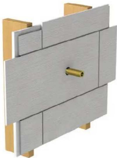
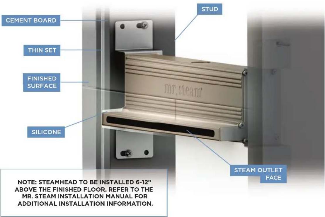
NOTE: Steamhead to be installed 6-12" above the finished floor. A 1.5" diameter hole in the steam room is required to mount the steamhead. Refer to the MrSteam Installation Manual for additional installation information.
STEP 2
Provide a 1 1/2" diameter hole in finished wall to mount the steamhead.
natural_image
3D architectural diagram of a wall-mounted door or fixture with wooden supports and a central brass component (no text or symbols)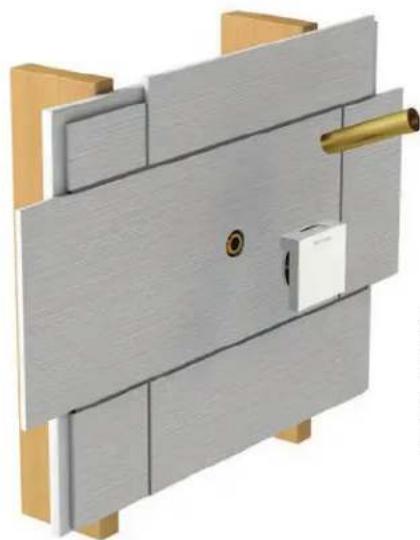
natural_image
3D mechanical assembly diagram showing a wooden bracket with a brass fitting and mounting bracket (no text or symbols)STEP 3
Remove Locating Nipple and attach steam head, with nipple sized for the finished wall thickness. Oil well must be facing up.
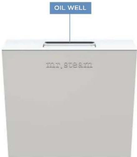
The Acrylic Shield (PN 103938 for round and 103938SQ for square) is for use when acrylic or other non-heat resistant materials are used for the steamroom enclosure. The Acrylic Shield is to be installed between the finished wall and the steamhead.
NOTE: Do not locate the control above or near the SteamHead
⚠ WARNING The information in this guide is designed to provide a general overview of how MrSteam® products are installed. All images and diagrams are for illustrative purposes only and may have been altered for presentation purposes. NEVER use this document for the Installation, Operation or Maintenance of any MrSteam® product. For installation, operation and maintenance information and instructions, only use the applicable MrSteam® Installation, Operation & Maintenance Manual(s). The specific Installation, Operation & Maintenance manual that is supplied with each MrSteam® product contains important information required for the safe and reliable installation and operation of the product. Failure to install any MrSteam® product according to the applicable manual may result in property damage, an inoperable system/control, or hazardous condition. If you do not have the applicable Installation, Operation & Maintenance manual please contact MrSteam® for a free copy, or download a copy from www.mrsteam.com. If you have any questions about the installation, operation or maintenance of any MrSteam® product please contact a customer or technical service representative using the contact information on the back cover of this guide or consult a properly licensed contractor, architect and/or design professional.
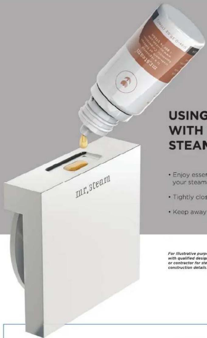
USING ESSENTIAL OILS WITH THE AROMASTEAM™ STEAMHEAD
- Enjoy essential oils by placing a drop or two, into your steamhead as shown in the illustration.
• Tightly close containers when storing oils. - Keep away from sources of ignition.
For illustrative purposes only. Consult with qualified designer, architect or contractor for steamroom construction details.
⚠ WARNING
- START WITH ONE DROP TO GAUGE STRENGTH AND SUITABILITY. LIMIT TO A MAXIMUM OF A FEW DROPS DURING A STEAMBATHING SESSION.
- PLACE THE DROPS INTO THE MRSTEAM AROMASTEAM STEAMHEAD WELL PRIOR TO TURNING ON THE STEAMBATH. DO NOT PLACE DROPS IN A HOT STEAM HEAD AS SERIOUS INJURY CAN RESULT IF YOU DO NOT FOLLOW THIS WARNING.
- SOME PEOPLE MAY FIND THAT THE AROMA MAKES THEM DIZZY AND THE USER SHOULD EXIT THE STEAM BATH IMMEDIATELY. IF SKIN IRRITATION OCCURS STOP USING THE OILS IMMEDIATELY. REMOVE ANY EXCESS OIL BY WASHING IN MILD
SOAP AND WATER. IF INGESTED, RINSE MOUTH WITH WATER. ADMINISTER WATER OR MILK TO DILUTE. CONTACT A PHYSICIAN IMMEDIATELY.
- USE ESSENTIAL OILS WITH CAUTION. ESSENTIAL OILS ARE FOR EXTERNAL USE ONLY. KEEP OUT OF REACH OF CHILDREN, ESSENTIAL OILS ARE HIGHLY CONCENTRATED AND ARE POTENT SUBSTANCES AND SHOULD NOT BE APPLIED DIRECTLY TO THE SKIN AS THEY CAN BE IRRITANTS. USE ESSENTIAL OILS WITH CAUTION.
- ESSENTIAL OILS AND/OR AROMATHERAPY CAN CAUSE INFLAMMATION, BURNS, HEADACHE, NAUSEA AND ALLERGIC REACTIONS. CONSULT A PHYSICIAN BEFORE USING AROMATHERAPY.
LINEAR STEAMHEAD
Do not locate the steam head in any location where the steam emission zone is near a seat, bench, or any space occupied by any persons, for a diagram of the steam emission zone.
For Illustrative purposes only. Consult with qualified designer, architect or contractor for steamroom construction details.
⚠ WARNING The information in this guide is designed to provide a general overview of how MrSteam® products are installed. All images and diagrams are for illustrative purposes only and may have been altered for presentation purposes. NEVER use this document for the Installation, Operation or Maintenance of any MrSteam® product. For installation, operation and maintenance information and instructions, only use the applicable MrSteam® Installation, Operation & Maintenance Manual(s). The specific Installation, Operation & Maintenance manual that is supplied with each MrSteam® product contains important information required for the safe and reliable installation and operation of the product. Failure to install any MrSteam® product according to the applicable manual may result in property damage, an inoperable system/control, or hazardous condition. If you do not have the applicable Installation, Operation & Maintenance manual please contact MrSteam® for a free copy, or download a copy from www.mrsteam.com. If you have any questions about the installation, operation or maintenance of any MrSteam® product please contact a customer or technical service representative using the contact information on the back cover of this guide or consult a properly licensed contractor, architect and/or design professional.
natural_image
Exterior view of a modern office building (no signage)STEP 1
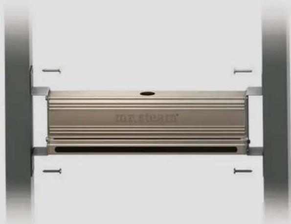
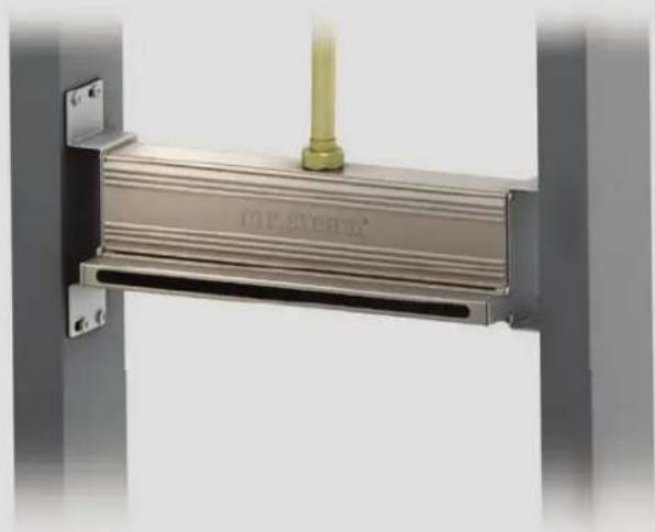
Determine the location of the fi nished wall surface. Mount the steam head between two studs using the four slotted holes. Use a level to ensure steam head is level in both the horizontal and vertical positions. Position the steam head face to be fl ush or extend 1/8" from the fi nished wall surface. 3/4" NPT Steam line opening should be on top. DO NOT mount steam head upside down.
natural_image
Metal mechanical component with a cylindrical pin and engraved text, mounted on a frame (no readable symbols or symbols)STEP 2
Attach steam piping to the 3/4" NPT opening on the top of the linear steam head.
natural_image
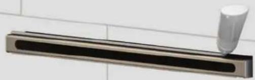
Close-up of a metallic wall-mounted fixture with a white cylindrical component inserted, mounted on a tiled surface (no text or symbols visible)STEP 3
After the fi nished wall surface has been installed use high temperature caulking around the steam outlet as required to make a water proof seal.
For illustrative purposes only. Consult with qualified designer, architect or contractor for steamroom construction details.
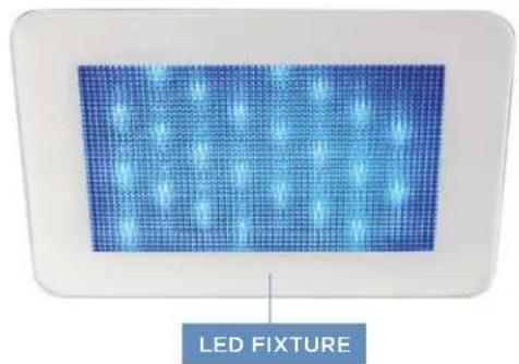
CHROMASTEAM3
natural_image
LED fixture panel with grid pattern and blue LED light effects (no text or symbols on the device itself)NOTE: FOR MOOD LIGHTING ONLY.
STEP 1
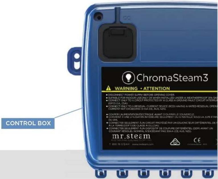
Locating the control box. Determine the desired location of the ChromaSteam3 control box outside the steam room in a dry location.
STEP 2
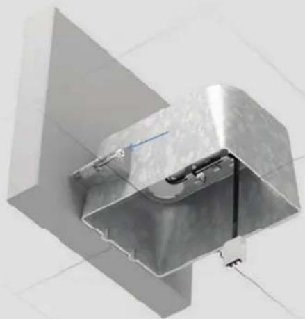
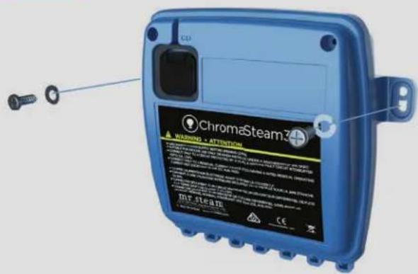
Installing the control box. Using screws and washers, affi x the control box to a stable vertical surface (e.g., stud) using the mounting holes on either side of the control box (Figure 1).
FIGURE 2
natural_image
3D rendering of a metallic mechanical component with internal wiring and mounting bracket (no text or symbols visible)For Illustrative purposes only. Consult with qualified designer, architect or contractor for steamroom construction details.
FIGURE 1
STEP 3
Install junction box. Remove one of the four knockouts from the junction box. The resulting hole will allow routing of the 30-foot control cable into the junction box. Locate the two tabs on the junction box, and line them up against a ceiling joist. The tabs locate the junction box proud of (slightly raised from) the joist. Screw the two screws into the ceiling joist to secure the junction box (Figure 2).
⚠ WARNING The information in this guide is designed to provide a general overview of how MrSteam® products are installed. All images and diagrams are for illustrative purposes only and may have been altered for presentation purposes. NEVER use this document for the Installation, Operation or Maintenance of any MrSteam® product. For installation, operation and maintenance information and instructions, only use the applicable MrSteam® Installation, Operation & Maintenance Manual(s). The specific Installation, Operation & Maintenance manual that is supplied with each MrSteam® product contains important information required for the safe and reliable installation and operation of the product. Failure to install any MrSteam® product according to the applicable manual may result in property damage, an inoperable system/control, or hazardous condition. If you do not have the applicable Installation, Operation & Maintenance manual please contact MrSteam® for a free copy, or download a copy from www.mrsteam.com. If you have any questions about the installation, operation or maintenance of any MrSteam® product please contact a customer or technical service representative using the contact information on the back cover of this guide or consult a properly licensed contractor, architect and/or design professional.
STEP 4
Connect the ChromaSteam3 fixture's pigtail to the 30-foot control cable in the junction box (Figure 3).
FIGURE 4
natural_image
3D rendering of a mechanical component with a central rod and base, shown without any text or symbols.STEP 6
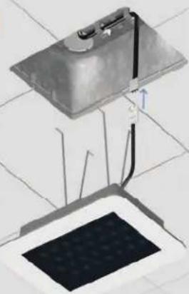
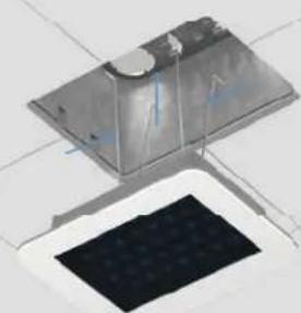
Squeeze the retention springs on the back of the fi xture and fi t them into the junction box (Figure 5). Insert the fi xture into the junction box and affi x it to the ceiling, being careful not to pinch the pigtail/control cable. Press fi r mly around edges of the fi xture to ensure adhesion to ceiling.
FIGURE 6
natural_image
Digital display with grid of blue LED lights and a white bottle, no visible text or symbolsFIGURE 3
natural_image
Diagram of a device with a panel and cable, no visible text or symbolsSTEP 5
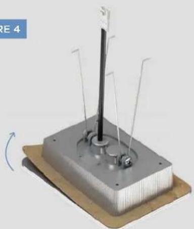
Clean the surface of the ceiling to ensure the double-stick adhesive of the fixture bonds completely to the ceiling. Peel off and discard the protective layer from the fixture's double-stick adhesive (Figure 4).
FIGURE 5
natural_image
3D rendering of a metallic electronic device with a black screen and wiring, no visible text or symbolsSTEP 7
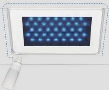
Apply a bead of silicone around the perimeter of the fi xture (Figure 6) as required to create a moisture seal between the fi xture and the steam room ceiling.
NOTE: CHROMASTEAM3 TO BE USED WITH THE ISTEAM®3 ONLY.
For illustrative purposes only. Consult with qualified designer, architect or contractor for steamroom construction details.
WARNING The information in this guide is designed to provide a general overview of how MrSteam® products are installed. All images and diagrams are for illustrative purposes only and may have been altered for presentation purposes. NEVER use this document for the Installation, Operation or Maintenance of any MrSteam® product. For installation, operation and maintenance information and instructions, only use the applicable MrSteam® Installation, Operation & Maintenance Manual(s). The specific Installation, Operation & Maintenance manual that is supplied with each MrSteam® product contains important information required for the safe and reliable installation and operation of the product. Failure to install any MrSteam® product according to the applicable manual may result in property damage, an inoperable system/control, or hazardous condition. If you do not have the applicable Installation, Operation & Maintenance manual please contact MrSteam® for a free copy, or download a copy from www.mrsteam.com. If you have any questions about the installation, operation or maintenance of any MrSteam® product please contact a customer or technical service representative using the contact information on the back cover of this guide or consult a properly licensed contractor, architect and/or design professional.
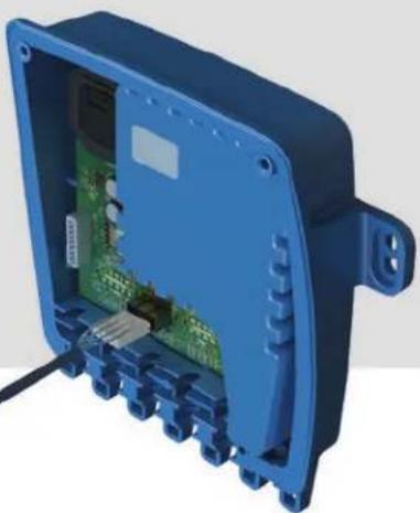
FIGURE 7
natural_image
3D rendering of an open blue electronic device casing with internal circuit board and connectors (no text or symbols visible)STEP 8
Connecting ChromaSteam3 Fixture to ChromaSteam3 Control Box. Remove the two cover screws from the front of the control box and remove the cover from the unit. Insert the free end of the control cable into the control box's LED receptacle (Figure 7).
natural_image
Close-up of a robotic arm operating on a circuit board with visible components (no text or symbols)STEP 9
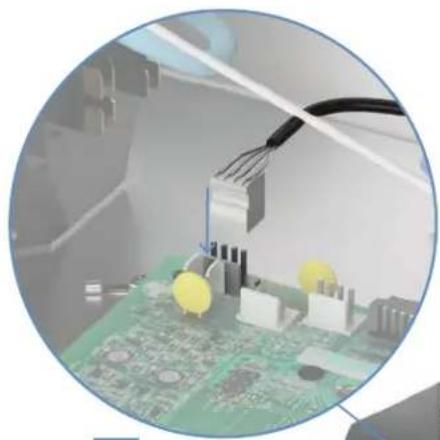
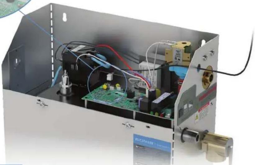
Connecting the ChromaSteam3 control box to the steam generator. Remove the cover and knockout on steam generator. Connect the controller cord directly to the steam generator's circuit board (A in Figure 8). Plug the ChromaSteam3 control box power cord into a 120V grounded electrical outlet.
A
natural_image
Interior view of an open electronic device enclosure with visible circuit boards, wires, and components (no readable text or symbols)FIGURE 8
WARNING The information in this guide is designed to provide a general overview of how MrSteam® products are installed. All images and diagrams are for illustrative purposes only and may have been altered for presentation purposes. NEVER use this document for the Installation, Operation or Maintenance of any MrSteam® product. For installation, operation and maintenance information and instructions, only use the applicable MrSteam® Installation, Operation & Maintenance Manual(s). The specific Installation, Operation & Maintenance manual that is supplied with each MrSteam® product contains important information required for the safe and reliable installation and operation of the product. Failure to install any MrSteam® product according to the applicable manual may result in property damage, an inoperable system/control, or hazardous condition. If you do not have the applicable Installation, Operation & Maintenance manual please contact MrSteam® for a free copy, or download a copy from www.mrsteam.com. If you have any questions about the installation, operation or maintenance of any MrSteam® product please contact a customer or technical service representative using the contact information on the back cover of this guide or consult a properly licensed contractor, architect and/or design professional.
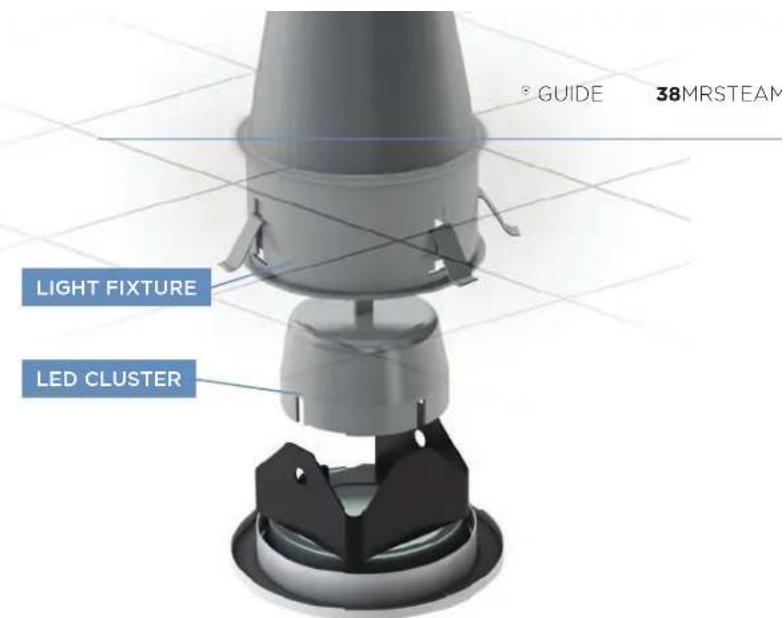
CHROMASTEAM 72
STEP 1
Determine the placement of the light.
IMPORTANT: DO NOT INSTALL THE FIXTURE ASSEMBLY (LIGHT) WHERE DIRECT CONTACT WITH STEAM OR WATER EMISSION COULD OCCUR. DO NOT INSTALL THE LIGHT IN A LOCATION WHERE IT COULD BECOME SUBMERGED.
STEP 2
The light requires a 41/4"diameter hole for mounting.
STEP 3
Provide electrical service (120VAC) with fl exible cable only. Pass cable through ceiling opening and wire fixture in accordance with NEC and local electrical code.
STEP 4
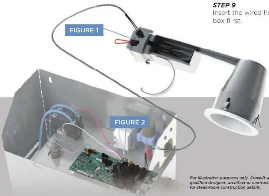
Route the 30 foot cable supplied with the Chroma Steam from your steam bath generator through one of the knockouts in the ChromaSteam light wiring box. Provide a suitable strain relief bushing.
IMPORTANT: The quick connect tabs should be on the generator side, the Molex connector should be routed to the light (Figure 2).
STEP 5
Connect the quick connect tabs to the control board in the generator at the location marked CHROMA.
STEP 6
Remove the red jumper wire shown in Figure 1 and discard. Connect the wire from the steam generator to the connector where the jumper was.
STEP 7
Connect the supply wires. Use suitable wirenuts (not included) to insulate and secure the supply connections.
STEP 8
Connect copper ground wire from wiring box to ground wire from electrical service using a wire nut to secure the connection.
STEP 9
Insert the wired housing into the ceiling junction box first.
NOTE: FOR MOOD LIGHTING ONLY.
NOTE: CHROMASTEAM72 IS NOT FOR USE WITH THE iSTEAM®3 CONTROL.
WARNING The information in this guide is designed to provide a general overview of how MrSteam® products are installed. All images and diagrams are for illustrative purposes only and may have been altered for presentation purposes. NEVER use this document for the Installation, Operation or Maintenance of any MrSteam® product. For installation, operation and maintenance information and instructions, only use the applicable MrSteam® Installation, Operation & Maintenance Manual(s). The specific Installation, Operation & Maintenance manual that is supplied with each MrSteam® product contains important information required for the safe and reliable installation and operation of the product. Failure to install any MrSteam® product according to the applicable manual may result in property damage, an inoperable system/control, or hazardous condition. If you do not have the applicable Installation, Operation & Maintenance manual please contact MrSteam® for a free copy, or download a copy from www.mrsteam.com. If you have any questions about the installation, operation or maintenance of any MrSteam® product please contact a customer or technical service representative using the contact information on the back cover of this guide or consult a properly licensed contractor, architect and/or design professional.
AUDIOSTEAM3

natural_image
Blue AudioSteam 3 device mounted on a wooden post, with two small screws attached nearby (no visible text or symbols on the device itself)STEP 1
Locate AudioSteam to prevent water from getting inside the device, AudioSteam should be mounted on two stable vertical surfaces (e.g., studs) as shown in (Figure 1).
Using screws and washers, firmly attach AudioSteam using the upper mounting holes, one at a time, on each side of the unit. Repeat the process for the lower mounting holes (Figure 1).
STEP 2
Using a Phillips-head screwdriver, remove the two cover screws from the front of the AudioSteam and remove the cover from the unit. Connect the outputs of AudioSteam.
STEP 3
For best reception, fully deploy the FM antenna in a vertical orientation outside of the AudioSteam housing.
If using the wired input, connect a 1/8" (3.5 mm) stereo audio cord (not included) to the auxiliary output, and route the cable through the strain relief channel. Connect the free end of the audio cord to an audio source.
STEP 4
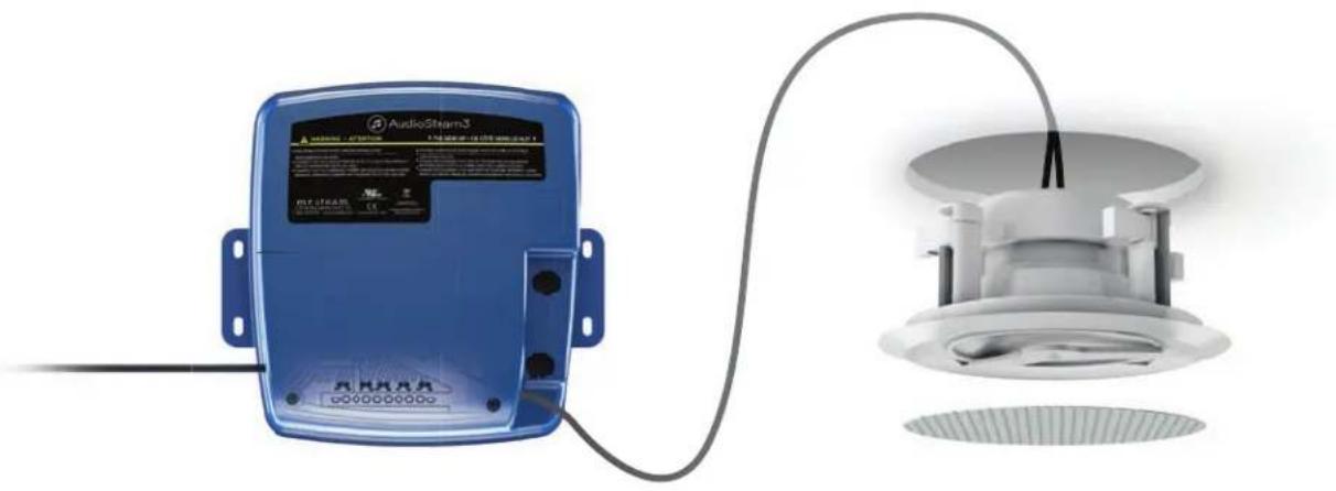
Connect 10-pin MATE-N-LOK adapter with attached wires — to the speaker outputs.
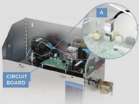
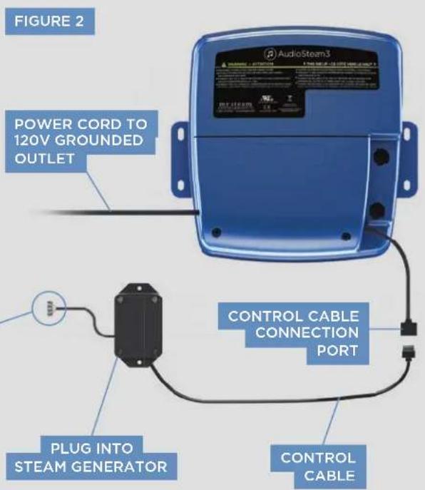
To operate the AudioSteam via iSteam3, you must connect the AudioSteam (Figure 2) to an internal connector in the steam generator.
STEP 5
Remove the steam generator cover and remove knockout on steam generator. Plug the control cable into the AudioSteam as shown. Connect the control cable directly to the steam generator's circuit board (A in Figure 2).
STEP 6
Plug the AudioSteam power cord into a 120V grounded electrical outlet. After the AudioSteam has been powered, supply power to the steam generator.
For Illustrative purposes only. Consult with qualified designer, architect or contractor for steamroom construction details.
WARNING The information in this guide is designed to provide a general overview of how MrSteam® products are installed. All images and diagrams are for illustrative purposes only and may have been altered for presentation purposes. NEVER use this document for the Installation, Operation or Maintenance of any MrSteam® product. For installation, operation and maintenance information and instructions, only use the applicable MrSteam® Installation, Operation & Maintenance Manual(s). The specific Installation, Operation & Maintenance manual that is supplied with each MrSteam® product contains important information required for the safe and reliable installation and operation of the product. Failure to install any MrSteam® product according to the applicable manual may result in property damage, an inoperable system/control, or hazardous condition. If you do not have the applicable Installation, Operation & Maintenance manual please contact MrSteam® for a free copy, or download a copy from www.mrsteam.com. If you have any questions about the installation, operation or maintenance of any MrSteam® product please contact a customer or technical service representative using the contact information on the back cover of this guide or consult a properly licensed contractor, architect and/or design professional.
MS-SPEAKER
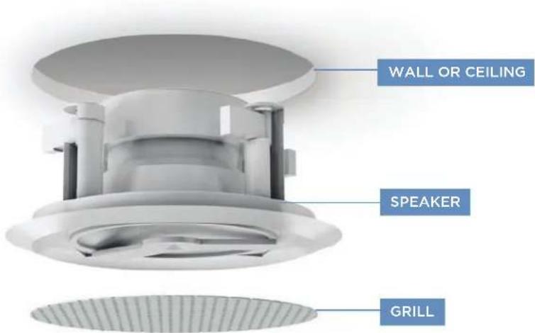
- Two flush-mount two-way speakers for steam/shower use, polypropylene cones, ABS frames with grills.
- Suitable for almost any source of audio input.
- Rated 60W peak power 8 ohms impedance with 1" tweeter for full range sound.
- Use only CL2 or CL3 UL listed wires to connect speakers to audio source.
• Available in Round (6 1/2") and Square (7") in both white and black designs.

natural_image
Close-up of two black circular filter or speaker covers with a mesh grille (no text or symbols visible)STEP 1
Determine the location of the speakers and cut the appropriate hole depending on speaker shape.
STEP 2
Connect speaker wire
natural_image
Blue AudioStar3 device connected to a ceiling-mounted fan (no visible text or symbols)STEP 3
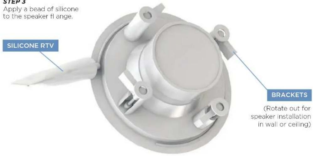
STEP 4
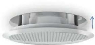
Place the speaker in the hole and tighten the screws on the integral mounting bracket to secure the speaker.
natural_image
Close-up of a circular white ventilation grille with a blue upward arrow indicating airflow or pressure (no text or symbols)WARNING The information in this guide is designed to provide a general overview of how MrSteam® products are installed. All images and diagrams are for illustrative purposes only and may have been altered for presentation purposes. NEVER use this document for the Installation, Operation or Maintenance of any MrSteam® product. For installation, operation and maintenance information and instructions, only use the applicable MrSteam® Installation, Operation & Maintenance Manual(s). The specific Installation, Operation & Maintenance manual that is supplied with each MrSteam® product contains important information required for the safe and reliable installation and operation of the product. Failure to install any MrSteam® product according to the applicable manual may result in property damage, an inoperable system/control, or hazardous condition. If you do not have the applicable Installation, Operation & Maintenance manual please contact MrSteam® for a free copy, or download a copy from www.mrsteam.com. If you have any questions about the installation, operation or maintenance of any MrSteam® product please contact a customer or technical service representative using the contact information on the back cover of this guide or consult a properly licensed contractor, architect and/or design professional.
SHOWER SEAT
STEP 1
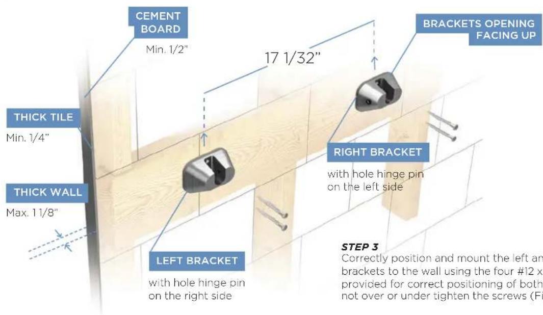
Mount the Wall Seat on a suitable surface like tile, granite or marble. Mount the seat at a height above the floor according to personal preference.
STEP 2
Using the template provided, drill four pilot holes into the header and 4 clearance holes into the tile. Use a level to ensure pilot holes are level. Be precise.
Do not oversize or undersize the pilot holes. Drill the pilot holes to the full 3" depth (length of the screws).
Fill the mounting holes with silicone (provided) before mounting the brackets to the wall as required to prevent moisture from penetrating into the wall and/or wall cavity.
FIGURE 1
For Illustrative purposes only. Consult with qualified designer, architect or contractor for steamroom construction details.
WARNING The information in this guide is designed to provide a general overview of how MrSteam® products are installed. All images and diagrams are for illustrative purposes only and may have been altered for presentation purposes. NEVER use this document for the Installation, Operation or Maintenance of any MrSteam® product. For installation, operation and maintenance information and instructions, only use the applicable MrSteam® Installation, Operation & Maintenance Manual(s). The specific Installation, Operation & Maintenance manual that is supplied with each MrSteam® product contains important information required for the safe and reliable installation and operation of the product. Failure to install any MrSteam® product according to the applicable manual may result in property damage, an inoperable system/control, or hazardous condition. If you do not have the applicable Installation, Operation & Maintenance manual please contact MrSteam® for a free copy, or download a copy from www.mrsteam.com. If you have any questions about the installation, operation or maintenance of any MrSteam® product please contact a customer or technical service representative using the contact information on the back cover of this guide or consult a properly licensed contractor, architect and/or design professional.
natural_image
3D illustration of a red bathtub with wall-mounted sensors and directional arrows, labeled 'FIGURE 2' (no text or symbols on the diagram itself)STEP 4
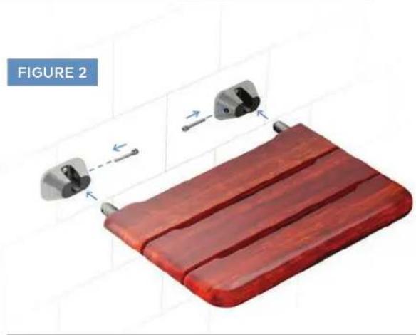
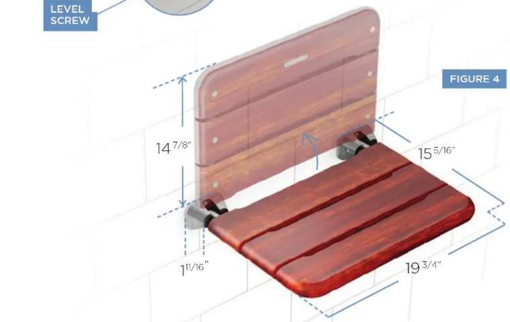
Insert seat assembly to brackets. Place seat with the MrSteam logo on the bottom. Insert hinge pins to both left and right brackets while the seat assembly is in vertical position. Securely tighten both hinge pins, using Allen wrench provided (Figure 2).
STEP 5
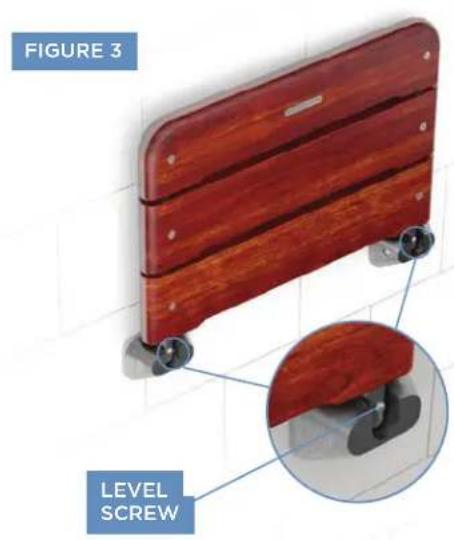
If the seat is not parallel to the floor when it is in the lowered or seated position use the allen wrench provided to adjust both level screws so the wallseat is parallel to the floor and it contacts both brackets at the same time (Figure 3).
WARNING The information in this guide is designed to provide a general overview of how MrSteam® products are installed. All images and diagrams are for illustrative purposes only and may have been altered for presentation purposes. NEVER use this document for the Installation, Operation or Maintenance of any MrSteam® product. For installation, operation and maintenance information and instructions, only use the applicable MrSteam® Installation, Operation & Maintenance Manual(s). The specific Installation, Operation & Maintenance manual that is supplied with each MrSteam® product contains important information required for the safe and reliable installation and operation of the product. Failure to install any MrSteam® product according to the applicable manual may result in property damage, an inoperable system/control, or hazardous condition. If you do not have the applicable Installation, Operation & Maintenance manual please contact MrSteam® for a free copy, or download a copy from www.mrsteam.com. If you have any questions about the installation, operation or maintenance of any MrSteam® product please contact a customer or technical service representative using the contact information on the back cover of this guide or consult a properly licensed contractor, architect and/or design professional.
STEP 1
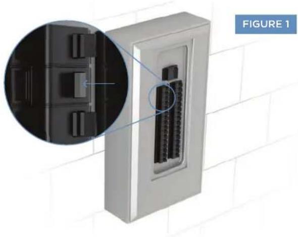
Disconnect power to the generator at the breaker box (Figure 1).
natural_image
Exterior view of a wall-mounted electrical enclosure with internal connectors, showing close-up detail (no text or symbols)STEP 2
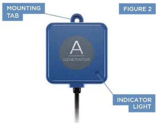
Locate SteamLinx A adjacent to the steam generator, mount to a secure surface using the mounting tab provided.
WARNING The information in this guide is designed to provide a general overview of how MrSteam® products are installed. All images and diagrams are for illustrative purposes only and may have been altered for presentation purposes. NEVER use this document for the Installation, Operation or Maintenance of any MrSteam® product. For installation, operation and maintenance information and instructions, only use the applicable MrSteam® Installation, Operation & Maintenance Manual(s). The specific Installation, Operation & Maintenance manual that is supplied with each MrSteam® product contains important information required for the safe and reliable installation and operation of the product. Failure to install any MrSteam® product according to the applicable manual may result in property damage, an inoperable system/control, or hazardous condition. If you do not have the applicable Installation, Operation & Maintenance manual please contact MrSteam® for a free copy, or download a copy from www.mrsteam.com. If you have any questions about the installation, operation or maintenance of any MrSteam® product please contact a customer or technical service representative using the contact information on the back cover of this guide or consult a properly licensed contractor, architect and/or design professional.
STEP 3
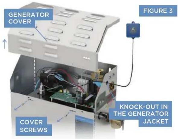
Remove generator cover. Route the SteamLinx® A cable through the knockout (Figure 3).
STEP 4
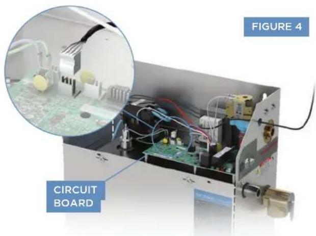
Plug the SteamLinx® A cable into one of the white connectors located at the far left side of the circuit board. Replace cover and screws.
STEP 5
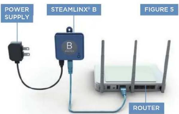
Plug the blue ethernet cable provided into an open ethernet port on the back of the router and the other end into SteamLinx® B. Plug the power supply into a 120V outlet (Figure 5).
STEP 6
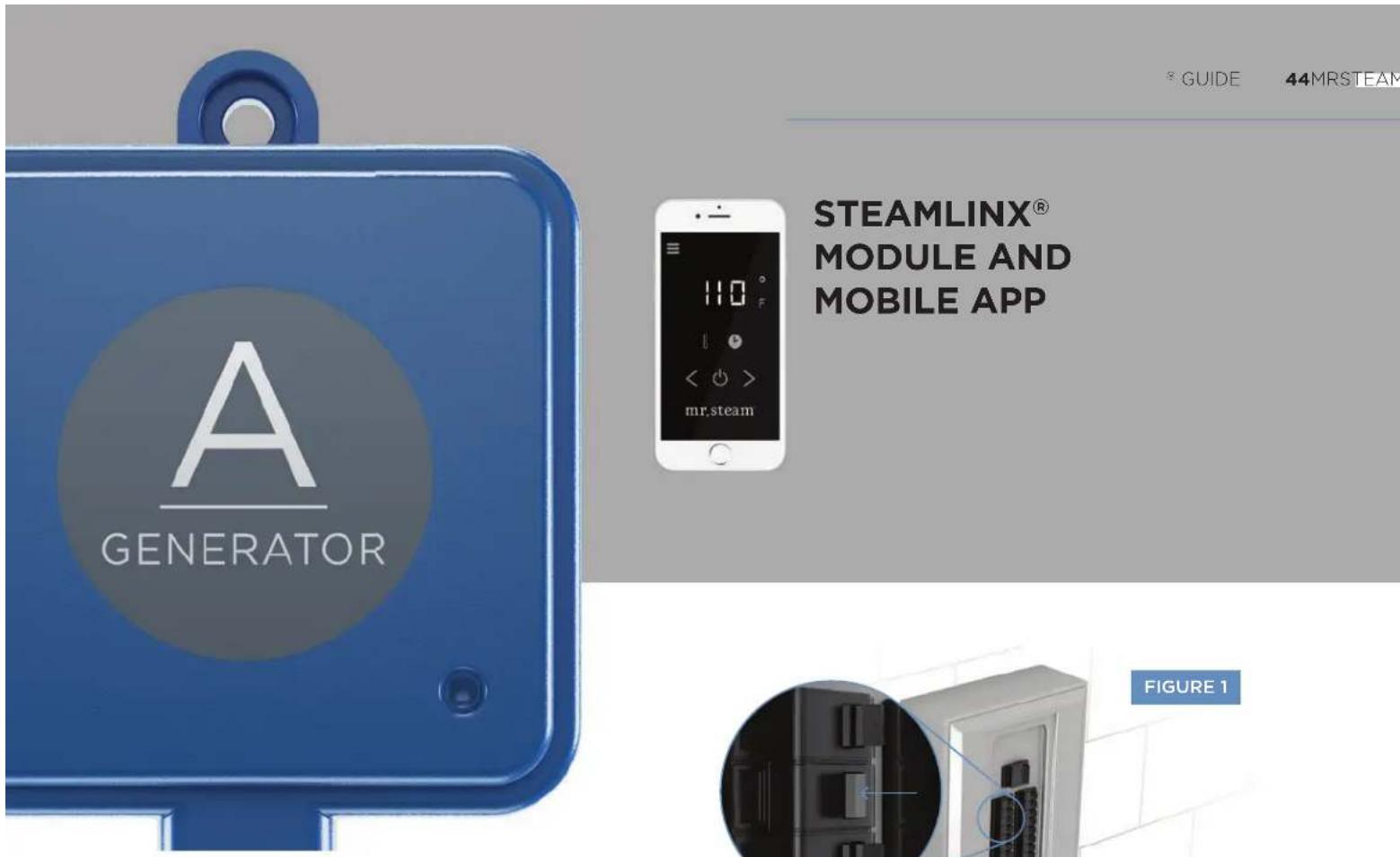
Ensure the mobile device is connected to the router's WiFi network. Download the SteamLinx® App from the App Store or Google Play.

Download on the App Store

GETTON Google Play
WARNING The information in this guide is designed to provide a general overview of how MrSteam® products are installed. All images and diagrams are for illustrative purposes only and may have been altered for presentation purposes. NEVER use this document for the Installation, Operation or Maintenance of any MrSteam® product. For installation, operation and maintenance information and instructions, only use the applicable MrSteam® Installation, Operation & Maintenance Manual(s). The specific Installation, Operation & Maintenance manual that is supplied with each MrSteam® product contains important information required for the safe and reliable installation and operation of the product. Failure to install any MrSteam® product according to the applicable manual may result in property damage, an inoperable system/control, or hazardous condition. If you do not have the applicable Installation, Operation & Maintenance manual please contact MrSteam® for a free copy, or download a copy from www.mrsteam.com. If you have any questions about the installation, operation or maintenance of any MrSteam® product please contact a customer or technical service representative using the contact information on the back cover of this guide or consult a properly licensed contractor, architect and/or design professional.
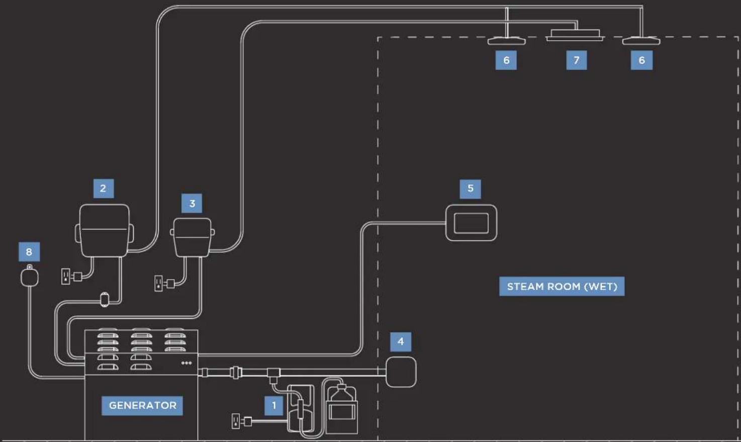
TYPICAL INSTALL OF DREAM PACKAGE SCHEMATIC
1 AromaSteam System
2 AudioSteam3
3 ChromaSteam3 Control Box
4 SteamHead
5 iSteam®3 Controller
6 Speakers
7 ChromaSteam Fixture
8 Steamlinx®
flowchart
graph TD
    A["GENERATOR"] --> B["2"]
    A --> C["3"]
    A --> D["4"]
    A --> E["1"]
    A --> F["5"]
    A --> G["6"]
    A --> H["7"]
    A --> I["6"]
    style A fill:#f9f,stroke:#333
    style B fill:#ccf,stroke:#333
    style C fill:#ccf,stroke:#333
    style D fill:#ccf,stroke:#333
    style E fill:#ccf,stroke:#333
    style F fill:#ccf,stroke:#333
    style G fill:#ccf,stroke:#333
    style H fill:#ccf,stroke:#333
    style I fill:#ccf,stroke:#333
A WARNING The information in this guide is designed to provide a general overview of how MrSteam® products are installed. All images and diagrams are for illustrative purposes only and may have been altered for presentation purposes. NEVER use this document for the Installation, Operation or Maintenance of any MrSteam® product. For installation, operation and maintenance information and instructions, only use the applicable MrSteam® Installation, Operation & Maintenance Manual(s). The specific Installation, Operation & Maintenance manual that is supplied with each MrSteam® product contains important information required for the safe and reliable installation and operation of the product. Failure to install any MrSteam® product according to the applicable manual may result in property damage, an inoperable system/control, or hazardous condition. If you do not have the applicable Installation, Operation & Maintenance manual please contact MrSteam® for a free copy, or download a copy from www.mrsteam.com. If you have any questions about the installation, operation or maintenance of any MrSteam® product please contact a customer or technical service representative using the contact information on the back cover of this guide or consult a properly licensed contractor, architect and/or design professional.
A leader and innovator in residential and commercial steam shower systems, spa products and experiences.
CONTACT US
HEADQUARTERS
Sussman-Automatic Corporation®
43-20 34th Street
Long Island City, NY. 11101 USA
tel 1-800-76 STEAM (767-8326)
WEST COAST
Sussman-Automatic Corporation®
9410 South La Cienega Blvd
Los Angeles, CA. 90301 USA
tel 1-800-72 STEAM (727-8326)
Or write to us at hello@mrsteam.com
Mr. Shear, Mr. Steam and pies, AirTempo. A lifetime of Pressure Aromatic, AutoLush, Audowizing, AutoSteam, Broadway Collection, Bullor Package, ChromicSound Spa Package, ChromicSistem, Clean Storm, Every Time, One Therapy, Day Spa, Digital T, Express Steam, Tempo, Tempo/Plus, Tempo/Stram, Real Good Inc, Fifth Avenue Collection, From Bedroom to Spa, HomeWizard, Bullor, iDream Packets: Genic Spa Packets: Isram, Fortone/Tempo/Plus, Linear, Linear Steamhead, Making Wellness a Way of Life, Metro Collection, Missauna Music Therapy, MyStream, Spa Package, Steam or Demand, Steam@Home, Smartzing Stem in a Box, Steamstart, Steamstop, SusanTherapy, Sussman, Torpo, Tale. The Intelligent Storbeth, Virtual Spa System, and Wermalows are registered trademarks of Sussman-Automatic Corporation.
HomeWizard is a trademark of Sussman-Automatic Corporation.
* Please refer to the applicable MrSteam Installation, Operation & Maintenance Manual, at mrsteam.com, for installation, operation and maintenance information and instructions. Failure to do so may result in property damage or an inoperable or hazardous condition. For safety and convenience, consult a qualified contractor, architect and/or design professional.
See product packaging and labeling for important information.
Copyright 2020 Sussman-Automatic Corporation. All rights reserved.
PUR100537, Revision 10/20
mr.steam

www.mrsteam.com
- QUICK SET UP GUIDE
- CONTENTS
- MR.STEAM®
- GENERATOR INSTALLATION
- LOCATING THE MR.STEAM® GENERATOR
- WATER FEED
- STEAM OUTLET PIPE
- MANUAL DRAIN LINE
- CONDENSATION PAN
- MAX STEAM GENERATOR INSTALLATION
- TYPICAL MS GENERATOR
- NEW
- FOR ADDITIONAL INFORMATION ON CONTROLS AND ACCESSORIES SEE CORRESPONDING QUICK GUIDES
- LOCATING THE iSTEAM®3, iTEMPO®, iTEMPO/PLUS® & AIRTEMPO® CONTROLS
- iSTEAM®3 CONTROL INSTALLATION
- STEP 1
- STEP 2
- AIRTEMPO® SURFACE MOUNT INSTALLATION
- AIRTEMPO® WIRELESS RECEIVER INSTALLATION
- AIRTEMPO® FLUSH MOUNT INSTALLATION
- STEP 3
- STEP 4
- STEP 5
- STEP 6
- iTEMPO OR iTEMPO/PLUS CONTROL INSTALLATION
- REMOTE TEMPERATURE SENSOR (MSTS)
- INSTALLING A REMOTE TEMPERATURE PROBE
- STEP 7
- CONNECTING THE CONTROL CABLE TO THE STEAM GENERATOR
- AROMASTEAM SYSTEM
- USING ESSENTIAL OILS WITH THE AROMASTEAM™ STEAMHEAD
- ⚠ WARNING
- LINEAR STEAMHEAD
- CHROMASTEAM3
- NOTE: CHROMASTEAM3 TO BE USED WITH THE ISTEAM®3 ONLY.
- STEP 8
- STEP 9
- CHROMASTEAM 72
- AUDIOSTEAM3
- MS-SPEAKER
- SHOWER SEAT
- TYPICAL INSTALL OF DREAM PACKAGE SCHEMATIC
- CONTACT US
Brand : Mr Steam
Model : MX4EC1
Category : Generator