
SXU24VKIT - Electrical enclosure Speco Technologies - Free user manual and instructions
Find the device manual for free SXU24VKIT Speco Technologies in PDF.


| Product Type | Outdoor Power Enclosure / Battery Backup System |
| Brand | Speco Technologies |
| Model | SXU24VKIT |
| Input Voltage | 115 VAC (90–132 VAC) or 230 VAC (180–264 VAC) selectable via slide switch |
| Output Voltage | 24 VDC (two 12V batteries in series) |
| Battery Configuration | Two 12V SLA batteries; series for 24V, parallel for 12V (model dependent) |
| Battery Capacity | Up to 100Ah per battery; 100Ah total in series, 200Ah in parallel |
| AC Battery Charger | Built-in with ON/OFF switch and voltage selector |
| DC Breakers | Two breakers (Breaker 1 and Breaker 2) for load protection |
| Mounting | Wall or pole mount using integrated mounting plate on back |
| Enclosure Material | White steel with black frame (outdoor rated) |
| Cable Entry | Provided cable gland for AC input |
| Terminals | Green Phoenix terminal for 12/24 VDC equipment output |
| DIN Rails | Yes, for mounting PoE switches and IP equipment |
| Safety Features | Breakers must be OFF before wiring; cold climate battery insulation required |
| Installation Guide | Step-by-step wiring instructions provided |
| Warranty | Contact Speco Technologies for details |
Frequently Asked Questions - SXU24VKIT Speco Technologies
User questions about SXU24VKIT Speco Technologies
0 question about this device. Answer the ones you know or ask your own.
Ask a new question about this device
Download the instructions for your Electrical enclosure in PDF format for free! Find your manual SXU24VKIT - Speco Technologies and take your electronic device back in hand. On this page are published all the documents necessary for the use of your device. SXU24VKIT by Speco Technologies.
USER MANUAL SXU24VKIT Speco Technologies
Mounting the Enclosure
The SXU and SXA enclosures are designed to be mounted to a wall or pole. The enclosure utilizes an integrated mounting plate on the back.

natural_image
Exterior view of a white industrial cabinet with black frame and door, labeled 'AL' at bottom (no other text or symbols)
WIRING
STEP 1
- Check to ensure that all breakers are in the "OFF" position before connecting any wires to the terminal blocks.

STEP 2
- If your part # ends with -12V, connect your two 12 Volt Batteries in parallel to keep the battery voltage at 12VDC.
- If your part # ends with -24V, connect your two 12 Volt Batteries in series to create a 24VDC Battery Bank.
Parallel Connection
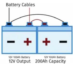
*In cold climates SLA batteries require insulation
Series Connection

Installation Guide
SXU24V
STEP 3
- Ensure that the Voltage Selector Switch is set to the appropriate Voltage. (Located to the Left of AC Input on Battery Charger)
- 115 VAC (90 to 132 VAC) *Slide Switch Towards Faceplate
- 230 VAC (180 to 264 VAC) *Slide Switch Away From Faceplate
STEP 4
- Passing through the provided cable gland, connect the AC power to the AC Battery Charger using the provided butt connectors.

Cable Gland

STEP 5
- Connect 12/24 VDC Equipment to the green phoenix terminal on the faceplate.
- Easily mount your PoE and IP equipment onto the DIN rails.
STEP 6
- Power up the system by first powering the Battery Charger with the ON/OFF switch located behind the AC Input.
- Then fl ip Breaker 1 followed by Breaker 2.
CONNECT WITH US TO DAY

1.800.645.5516

SPECOTECH.COM

natural_image
Construction site with two workers in safety vests and helmets, surrounded by scaffolding and debris (no visible text or symbols)Brand : Speco Technologies
Model : SXU24VKIT
Category : Electrical enclosure