Vision - Lock Lockly - Free user manual and instructions
Find the device manual for free Vision Lockly in PDF.


| Product Type | Smart Lock with HD Video Doorbell |
| Model | Vision |
| Brand | Lockly |
| Edition | Deadbolt Edition |
| Power Source | 4 AA batteries (3 initially, 4th with program button) |
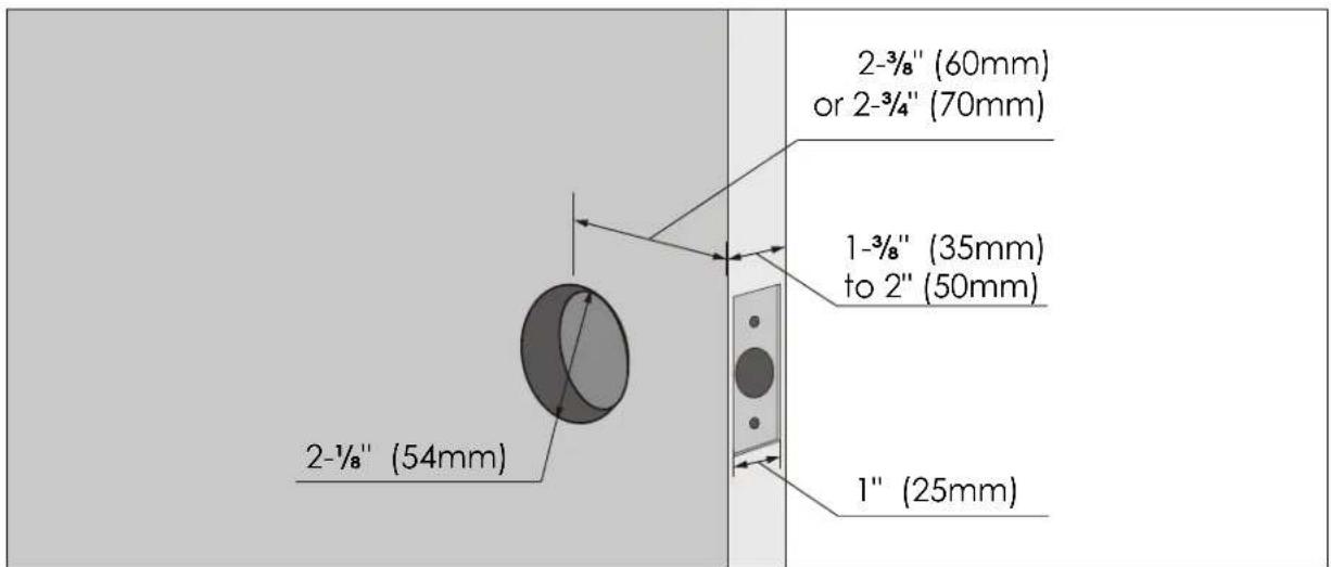
| Compatible Door Thickness | 1-3/8" to 2" (35-50 mm) |
| Backset Compatibility | 2-3/8" or 2-3/4" (60 or 70 mm) |
| Cross Bore Diameter | 2-1/8" (54 mm) |
| Deadbolt Hole Diameter | 1" (25 mm) |
| Key Override | Yes (physical keys included) |
| Video Doorbell | HD video, two-way audio |
| Connectivity | Wi-Fi via Secure Link Hub, Bluetooth |
| Smart App | Lockly App (iOS/Android) |
| Self-Calibration | Automatic door swing detection and self-check |
| Security Certification | FCC Part 15, IC RSS, California Proposition 65 |
| Weight (approx.) | 2.5 lbs (1.1 kg) |
| Materials | Zinc alloy, stainless steel, plastic |
| Battery Life (estimate) | 6-12 months with normal use |
| Operating Temperature | 14°F to 122°F (-10°C to 50°C) |
| Included Components | Exterior assembly, interior assembly, mounting plate, deadbolt, strike plate, screws, adhesive strips, keys, battery cover, manual |
| Warranty | 1 year limited (subject to terms) |
Frequently Asked Questions - Vision Lockly
User questions about Vision Lockly
0 question about this device. Answer the ones you know or ask your own.
Ask a new question about this device
Download the instructions for your Lock in PDF format for free! Find your manual Vision - Lockly and take your electronic device back in hand. On this page are published all the documents necessary for the use of your device. Vision by Lockly.
USER MANUAL Vision Lockly
LOCKLY
VISION
SMART LOCK w/ HD VIDEO DOORBELL
INSTALLATION GUIDE DEADBOLT EDITION
STEP 1: PREPARE DOOR FOR INSTALLATION
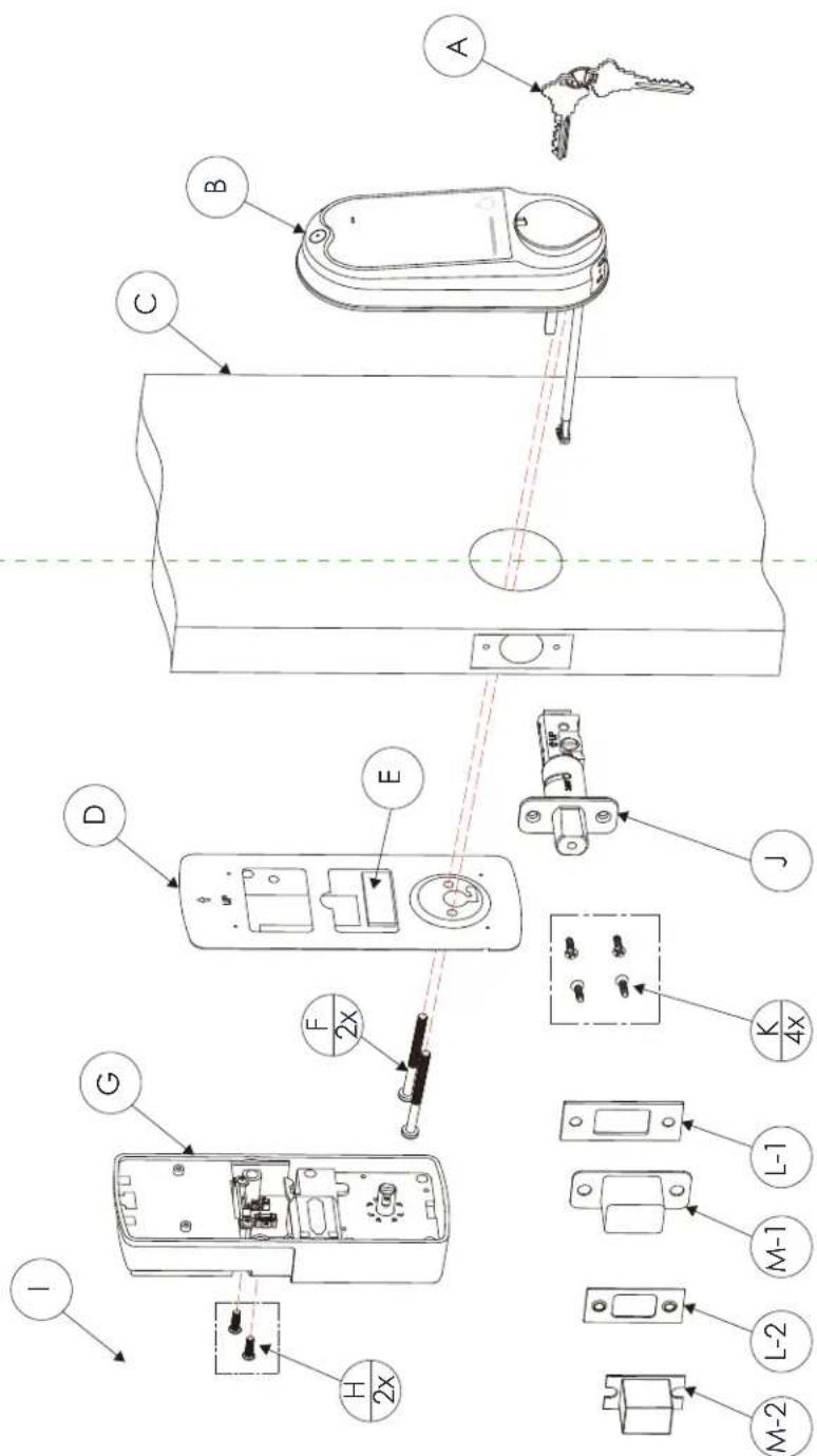
Lockly Secure can be fitted for both right swing doors and left swing doors.
| Labeled As | Description Count | |
| A Keys 1 | ||
| B Exterior Assembly 1 | ||
| C Exterior 1 | ||
| D Mounting Plate 1 | ||
| E Adhesive 1 | ||
| F UNF10-32*60mm Screw 2 | ||
| G Interior Assembly 1 | ||
| H PM4*12MM Screw 2 | ||
| I Battery Cover 1 | ||
| J Deadbolt 1 | ||
| K KA4*20MM Screw 4 | ||
| L-1 Strike Plate (Optional) 1 | ||
| M-1 | Adhesive (Optional) | 1 |
| L-2 | Strike Plate (Optional) | 1 |
| M-2 | Strike Plate (Optional) | 1 |
Parts List
STEP 1: PREPARE DOOR FOR INSTALLATION
1.1: To complete installation, you would need the following:

Flathead Screwdriver

Phillips Screwdriver
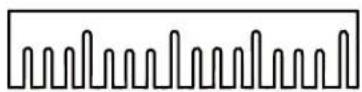
Ruler

natural_image
Line drawing of a drill-type tool with handle and screwdriver (no text or symbols)Screwdriver with drill bits (optional)
1.2: Prepare door and remove existing lock. If necessary, use provided Installation Template to prepare door.
STEP 2. ADJUST DEADBOLT AND INSTALL
2.1: Deadbolt slit hole must be aligned to the center of the door hole. If not adjust as shown below:
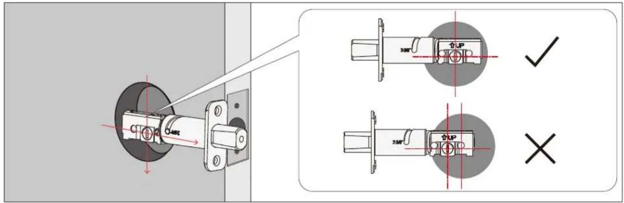
2.1.1: Wear gloves during adjustment to prevent pinching your hands)
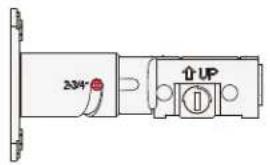
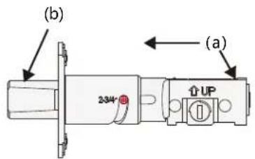
Push the crank (a) to extend the deadbolt (b)
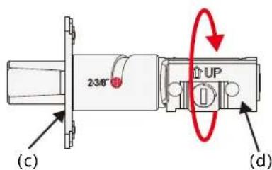
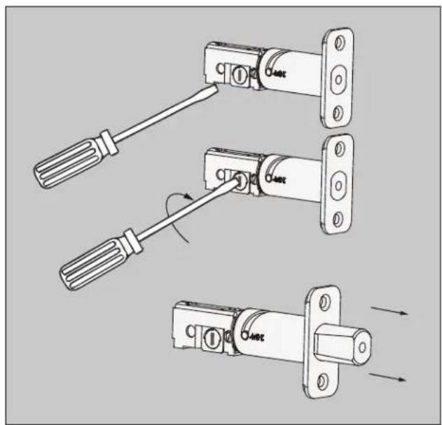
2.2: Extend the deadbolt by inserting a flat head screwdriver on the slit hole or by pushing the crank towards the metal face plate.
2.3: Insert the Deadbolt to the edge door hole, make sure that its right side up and the slit hole is in vertical position, then fastened with 2 screws (K)
natural_image
Technical illustration of three mechanical lock components with a screwdriver, showing different assembly states (no text or symbols present)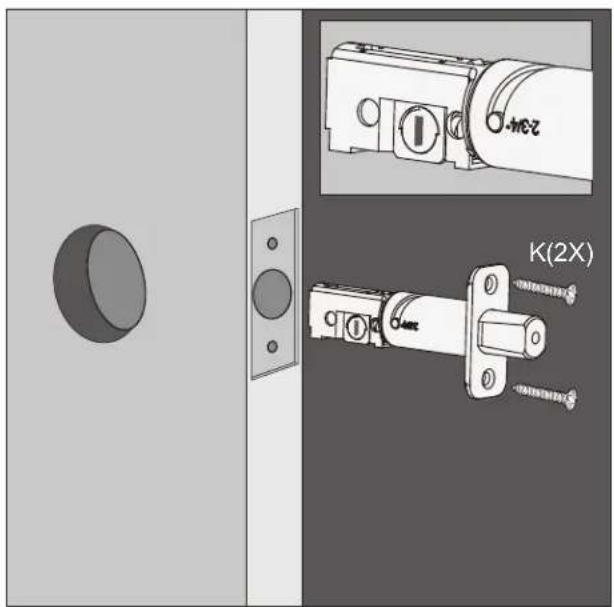
natural_image
Technical illustration of a door lock assembly with mounting bracket and close-up views (no text or symbols)STEP 3. INSTALLING THE EXTERIOR ASSEMBLY
3.1: To secure Exterior Assembly of lock, peel the cover off the adhesive strips
3.2: Before placing the exterior assembly on the door, make sure the torque blade is in vertical position and the deadbolt is extended.
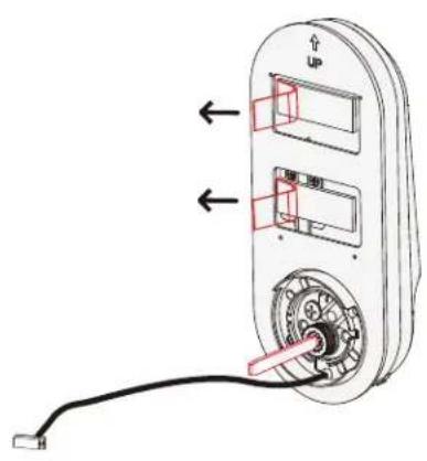
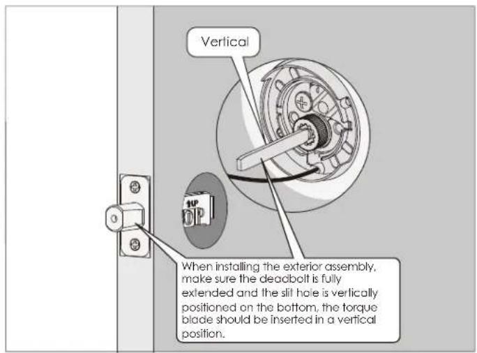
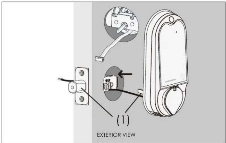
3.3: Place the exterior assembly on the door by inserting the torque blade on a vertical position to the deadbolt slit hole + and guide the cable under the deadbolt. Secure and fastened with the adhesive strips.
STEP 4. INSTALLING THE INTERIOR ASSEMBLY
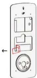
4.1: Peel of the cover off the adhesive strip on the mounting plate.
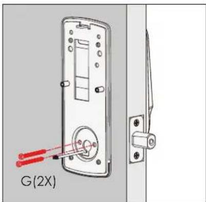
4.3: Without using any tools, insert 2 screws (G) on the side of the torque blade. By using hand carefully, turn the screws clockwise to catch the thread, then counter clockwise to make sure they are not cross threaded and turns smoothly. Make five turns before using a screw driver to tighten the screws until the mounting plate is securely placed to the door.
natural_image
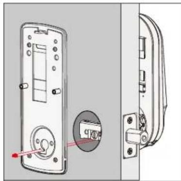
Technical line drawing of a door lock mechanism with mounting bracket and side panel (no text or symbols)4.2: Place the mounting plate on the interior side of the door. Guide the cable to the opening ear on the side of mounting plate and make sure the torque blade is at the center of the mounting plate.
natural_image
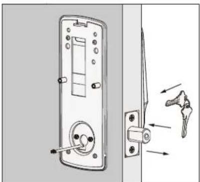
Technical diagram of a door lock mechanism with an arrow indicating the angle of change (no text or symbols present)4.4: Before installing the interior assembly, use the physical key and try to unlock/lock to check if the deadbolt is moving and not stuck. Do not forget to take out the key before proceeding to next steps.
STEP 4. INSTALLING THE INTERIOR ASSEMBLY
4.5:
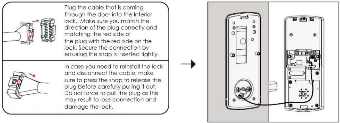
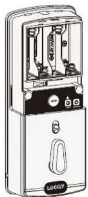
4.6: Before placing the interior assembly to the mounting plate, ensure the thumb turn is vertical.
4.7: Place the interior assembly against the mounting plate and make sure the torque blade is inserted to the thumb turn shaft.
4.8 Secure the interior assembly with 2 screws (I)
natural_image
Line drawing of a portable electronic device with control panel and buttons (no text or symbols)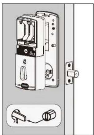
natural_image
Diagram of a door lock mechanism with a close-up of the lock and handle (no text or symbols)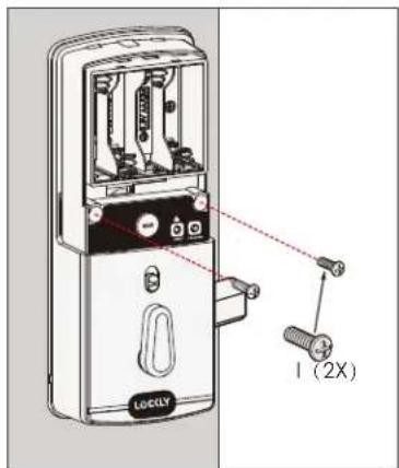
STEP 5. INSTALLING BATTERIES
natural_image
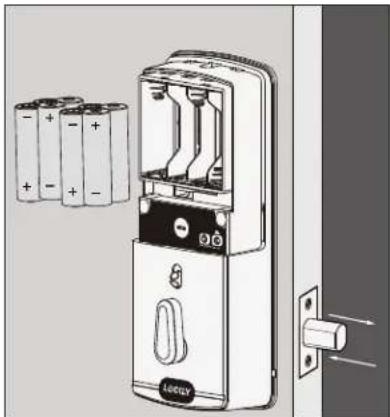
Diagram of a door lock mechanism with battery plates and a door, showing no text or symbols5.1: First install 3 of the 4 batteries. Before installing the last battery, press and hold the PROGRAM button ☐ while installing the last battery until you hear a beep from Lockly.
Lockly will then perform a self check and the keypad screen will start to initiate. This self check will automatically determine and set your door lock to a left open or right open door.
The self-check process is very important step to ensure the installation is done properly.
After the lock finished the self-check, manually lock and and unlock your door by using the thumb turn and the key to make sure the deadbolt moves smoothly. If you feel that there is a tight tension while you are turning, it means that the lock may have not been installed straight. Go back to Step 2 and re-install the lock.
To check if your lock was installed correctly, manually unlock your door by using the thumb turn, then brush your hand across the screen on the outside. Your lock should lock the deadbolt. If your lock automatically unlocks after it has been locked, it means that your lock was installed incorrectly - proceed to Step 2 to make sure your lock was installed with the deadbolt extended and the torque blade was inserted vertically while the deadbolt was extended.
natural_image
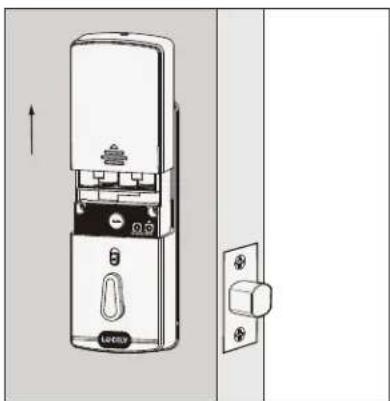
Technical line drawing of a door lock mechanism with directional arrows (no text or symbols)5.2: After you checked that the lock manually lock and unlock and deadbolt moves smoothly, Install the battery cover with screw (H) and fastened.
STEP 6: INSTALLING THE DOOR STRIKE
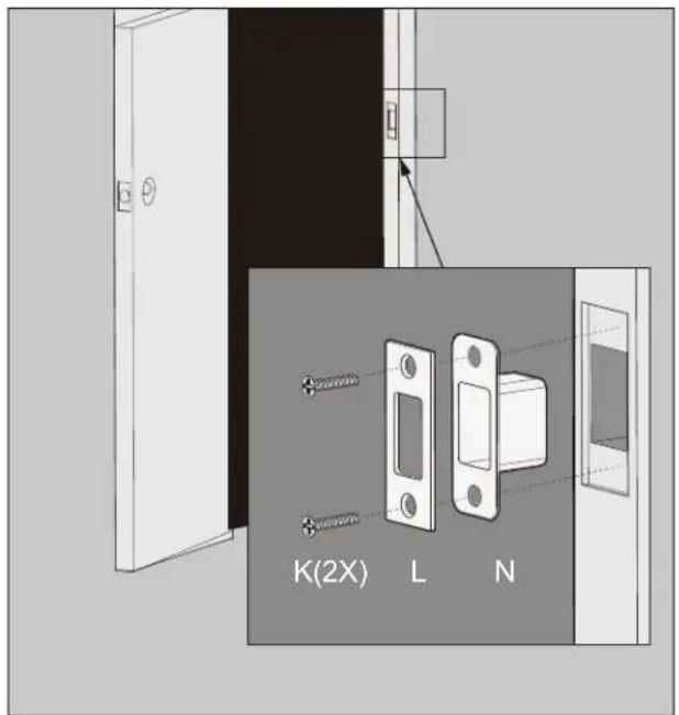
Install the door strike.
Install the door strike to your door frame and proceed to the last step of installation of your new lock. You may use our supplied door strike or use your existing door strike as long as the dead bolt moves smoothly in and out of the door strike.
As there are many types of doors, you may need to make slight adjustments so the dead bolt moves smoothly. If anything is rubbing against the deadbolt when locking and unlocking, you may experience a warning sound (rapid beeping) indicating that the lock is experiencing misalignment or something is blocking the deadbolt.
Congratulations! You have completed the Lockly Vision installation.
To complete the setup of Lockly Vision smart lock and video doorbell, download the Lockly App and follow on-screen instructions to complete your setup and installation.



Scan or visit Lockly.com/app

Certified
FCC Warning:
This device complies with Part 15 of the FCC Rules. Operation is subject to the following two conditions: (1) This device may not cause harmful interference, and (2) this device must accept any interference received, including interference that may cause undesired operation.
NOTE 1: This equipment has been tested and found to comply with the limits for a Class B digital device, pursuant to part 15 of the FCC Rules. These limits are designed to provide reasonable protection against harmful interference in a residential installation. This equipment generates, uses and can radiate radio frequency energy and, if not installed and used in accordance with the instructions, may cause harmful interference to radio communications. However, there is no guarantee that interference will not occur in a particular installation. If this equipment does cause harmful interference to radio or television reception, which can be determined by turning the equipment off and on, the user is encouraged to try to correct the interference by one or more of the following measures:
- Reorient or relocate the receiving antenna.
- Increase the separation between the equipment and receiver.
- Connect the equipment into an outlet on a circuit different from that to which the receiver is connected.
- Consult the dealer or an experienced radio/TV technician for help.
NOTE 2: Any changes or modifications to this unit not expressly approved by the party responsible for compliance could void the user's authority to operate the equipment.
FCC Radiation Exposure Statement
The Secure Link Wi-Fi Hub complies with FCC radiation exposure limits set forth for an uncontrolled environment. It should be installed and operated with minimum distance 20cm between the radiator & your body.
IC WARNING
This device contains licence-exempt transmitter(s) that comply with Innovation, Science and Economic Development Canada's licence-exempt RSS(s).
Operation is subject to the following two conditions:
NEXT >
(1) This device may not cause interference.
(2) This device must accept any interference, including interference that may cause undesired operation of the device.
WARNING: This product contains DEHP and other chemicals known to the State of California to cause cancer and birth defects, or other reproductive harm. For more information go to www.P65Warnings.ca.gov

VISION

We're here to help!
help@lockly.com
https://lockly.com/help
LOCKLY VISION
For an online version of this installation guide and videos, visit:
http://lockly.com/help
- LOCKLY
- VISION
- STEP 1: PREPARE DOOR FOR INSTALLATION
- STEP 2. ADJUST DEADBOLT AND INSTALL
- STEP 3. INSTALLING THE EXTERIOR ASSEMBLY
- STEP 4. INSTALLING THE INTERIOR ASSEMBLY
- 4.5:
- STEP 5. INSTALLING BATTERIES
- STEP 6: INSTALLING THE DOOR STRIKE
- Install the door strike.
- Certified
- FCC Warning:
- FCC Radiation Exposure Statement
- IC WARNING
- LOCKLY VISION
Brand : Lockly
Model : Vision
Category : Lock