AVL-1050-D - Monitor Avocor - Free user manual and instructions
Find the device manual for free AVL-1050-D Avocor in PDF.


| Product Type | Ultrawide 5K Monitor |
| Screen Size | 105 inches (diagonal) |
| Aspect Ratio | 21:9 |
| Resolution | 5120 x 2880 (5K) @ 60Hz |
| Backlight | LED |
| Brightness | 400 cd/m² |
| Contrast Ratio | 4000:1 |
| Response Time | 6.5 ms (typ) |
| Viewing Angle | 178° horizontal / 178° vertical |
| Color Depth | 30-bit deep color |
| Built-in Speakers | 2 x 15W (forward facing) |
| Touch | Not available (non-interactive) |
| Connectivity | 1x HDMI 2.1, 3x HDMI 2.0, 1x DisplayPort 1.4, 1x USB-C (100W PD), 3x USB-B, 4x USB-A, HDMI out, 3.5mm audio out, optical SPDIF, RS232, 2x LAN (RJ-45) |
| Power Consumption | Max 250W, Standby ≤0.5W |
| Power Supply | AC 100-240V, 50/60Hz |
| Dimensions (W x H x D) | 25160.6 x 1123.3 x 96.3 mm (98.84 x 44.22 x 3.79 in) |
| Net Weight | 99 kg (218.26 lbs) |
| VESA Mount | 1000 x 400 mm |
| Sensors | Presence, ambient light, temperature, humidity, CO2/VOC |
| OPS Slot | Yes |
| Warranty | 1 Year Limited (Return to Base) |
| Included Accessories | Remote control, batteries, power cables (US/UK/EU), HDMI cable 3m, USB cable 3m, USB-A-B adapter, wall mount kit, mounting brackets |
Frequently Asked Questions - AVL-1050-D Avocor
User questions about AVL-1050-D Avocor
0 question about this device. Answer the ones you know or ask your own.
Ask a new question about this device
Download the instructions for your Monitor in PDF format for free! Find your manual AVL-1050-D - Avocor and take your electronic device back in hand. On this page are published all the documents necessary for the use of your device. AVL-1050-D by Avocor.
USER MANUAL AVL-1050-D Avocor
L-SERIES USER MANUAL
for models AVL-1050-T & AVL-1050-D
TABLE OF CONTENTS
Compliance Information ....3
Declaration of Conformity....3
Caution 3
Industry Canada (ICES-003)....3
Product Disposal ....3
Disposal of Old Electrical and Electronic Equipment 4
Introduction 5
About This Manual....5
Textual Conventions....5
Graphic Conventions....6
What's in the Box? 7
Specifications....8
The display, at a glance 10
Display Front.... 10
Detail: Front Panel Middle Sensors.... 10
Detail: Front Panel power button & Sensors.... 11
Back Panel View....12
Side Panel View....13
Detail: I/O Panel.... 14
Bottom Panel View 15
Detail: Bottom-panel WiFi, USB Ports, and Power input/Output 15
Detail: ethernet/control panel 16
The Remote Control 17
Remote Control Batteries.... 18
Installation.... 19
Ambient Considerations....19
Ambient Light 20
Ambient Temperature 20
Ventilation....20
L-SERIES USER MANUAL | 2
Mounting the Display 21
Installation via the included wall mount 21
Wi-Fi module installation.... 24
OPS Module Installation.... 25
Operation 27
The Home Screen....27
UiQ Settings.... 28
External Control 37
RS232 Connection and Port Configuration 37
LAN Control Configuration....37
Command and Response Format.... 37
Serial Command List 38
Avocor: One-year Limited Warranty 41
Coverage 41
Exclusions....41
Concealed Damage....42
Customer Data 42
Services....43
COMPLIANCE INFORMATION
DECLARATION OF CONFORMITY
Avocor hereby declares that the following Product Model Number:
AVL-1050-T / AVL-1050-D conforms to the provisions of the following regulations:
PENDING
CAUTION
Any changes or modifications not expressly approved by the grantee of this device could void the user's authority to operate the equipment.
INDUSTRY CANADA (ICES-003)
PENDING
PRODUCT DISPOSAL
The Product contains small amounts of tin, lead, and/or mercury. Disposal of these materials may be regulated due to environmental considerations.
DISPOSAL OF OLD ELECTRICAL AND ELECTRONIC EQUIPMENT
Applicable throughout the European Union and other European countries with separate collection programs

This symbol, found on your product or on its packaging, indicates that this product should not be treated as household waste when you wish to dispose of it. Instead, it should be handed over to an applicable collection point for the recycling of electrical and electronic equipment. By ensuring that this product is disposed of correctly, you will help prevent potential negative consequences to the environment and human
health, which could otherwise be caused by inappropriate disposal of this product.
The recycling of materials will help to conserve natural resources. This symbol is only valid in the European Union. If you wish to discard this product, please contact your local authorities or dealer, and ask for the correct method of disposal.
INTRODUCTION
Your new Avocor L-series display is an ultrawide, ultra-high-definition display supporting full range 5K@60hz resolution, and multiple source inputs for your devices. This series comes in both an interactive touch model, and a non-interactive model.
Avocor follows an agnostic approach to developing displays: they are compatible with a wide range of hardware and software, making them a great addition to any interactive meeting-room solution. Whether you need a virtual meeting space for your conference room, or a powerfully adaptive whiteboard or presentation hub for your classroom, the Avocor L-series will exceed your expectations.
ABOUT THIS MANUAL
This user manual was written to help you get the most out of your display. In addition to detailed descriptions of the display and its features, this guide will walk you through the installation and setup processes, while also providing tips, tricks, and best practices on how best to utilize the display.
We make every effort to ensure that this manual is accurate as of the date it was printed. However, it may require periodic updating due to ongoing product improvements and customer feedback. Find the latest version of our manuals at Avocor.com.
TEXTUAL CONVENTIONS
The following textual conventions are used in this manual to denote certain actions or information for clarification purposes. Here are the details:
- Remote control and display keypad controls are set in CAPS. For example, "Press OK on the remote control to accept your changes."
- Menus in the OSD and computer interface are in bold. The ">" symbol is used to help denote submenu navigation. For example, "Open Display > Picture > Advanced Settings to adjust various picture settings."
- Keyboard keys with functional names are capitalized and set in
. For example, "press to make your selection." - In addition to the above, underlining, italics, or a combination of the two are used periodically to help emphasize key points in the text of this manual.
GRAPHIC CONVENTIONS
The following symbols appear throughout this manual to emphasize key points. Keep these in mind not only to benefit from their advice, but also to avoid problems with the display or personal injury.

TIP Highlights helpful guidelines and best practices for using certain features.

NOTE Provides supplemental information and emphasize text of special significance.

CAUTION Alerts that given actions may degrade the performance of the display or cause a malfunction.

WARNING Alert that a given action may result in damage to equipment or personal injury.

DANGER Alert that a given action may cause serious personal injury or death.
WHAT'S IN THE BOX?
- Avocor L-Series Interactive Display
- Quick Start Leaflet with QR code
- Remote Control & Batteries
• (2) Touch Stylus 3mm -
Power Cables
-
US Cable 2m
- UK Cable 2m
- European Cable 2m
• (1) HDMI cable 3m
(1) USB-A 3.0 cable 3m
• (2) USB-A-B Adapter
• (1) 1000x400 Wall Mount
• (2) Mounting brackets
SPECIFICATIONS
| AVL-1050-T | AVL-1050-D | |
| Diagonal Size (Inches) | 105" | |
| Backlight | Backlit LED | |
| Aspect Ratio | 21:9 | |
| Resolution | 5120 x 2880 @ 60Hz | |
| Response Time | 6.5 ms (Typ) | |
| Brightness | 400 (cd/m2) | |
| Contrast Ratio | 4000:1 | |
| Viewing Angle | 178°/178° | |
| Supported Colors | 30 Bit Deep Color | |
| Display Orientation | Landscape | |
| Touch System | ||
| Touch | Up to 40 points Avocor Intelligent Touch | N/A |
| Glass | Optically bonded, anti-glare, anti-fingerprint | Anti-glare, anti-fingerprint |
| Interface | 3 x USB-B inputs | |
| Connectivity | ||
| Top inputs | 2 x USB-A 3.0 hub | |
| Side inputs | 1 x Type-C (100W PD), 4 x HDMI (1 x 2.1, 3 x 2.0), 3 x USB-B 2.0 touch, 1 x DisplayPort 1.4, 2 x USB-A 3.0 hub, 1 x USB-A service port, HDMI out | |
| Bottom inputs | 2 x USB-A 2.0 hub | |
| Audio | 1x 3.5mm Audio Out, 1x Optical (SPDIF) | |
| Control | 1 x IR input, 1x RS232, 2x LAN Ethernet (RJ-45) | |
| OPS Slot | Yes | |
| Audio | |
| Built-in Speakers | 2x 15W - Forward Facing |
| Display Functions | |
| Auto-source detection, Source Preview, Blank, Freeze | |
| Physical Specifications | |
| Product Dimensions | 25160.6 x 96.3 x 1123.3 mm | 98.84 x 3.79 x 44.22 in |
| Shipping Dimensions | 2703 x 425 x 1255 mm | 106.42 x 16.73 x 49.41 in |
| Weight | Net: 99kg | 218.26 lbs / Gross: TBD |
| Wall Mount (VESA) | 1000 x 400 mm |
| IPC Mount | 100 x 100 mm |
| Handles | Yes |
| Sensors | |
| Type | Presence, ambient light, color temperature, temperature, humidity, CO2/VOCS |
| Power | |
| Power Supply | AC100 - 240V (Worldwide), 50/60Hz |
| Max Power Consumption | 250W |
| Standby | ≤0.5W |
| Environmental | |
| Operating Temperature | 0°C ~ 40°C / 32°F ~ 104°F |
| Storage Temperature | -20°C ~ 60°C / -4°F ~ 140°F |
| Humidity | 10% ~ 90% |
| Warranty | |
| Global | 1 Year RTB with optional upgrades available (contact your reseller for more info) |
THE DISPLAY, AT A GLANCE
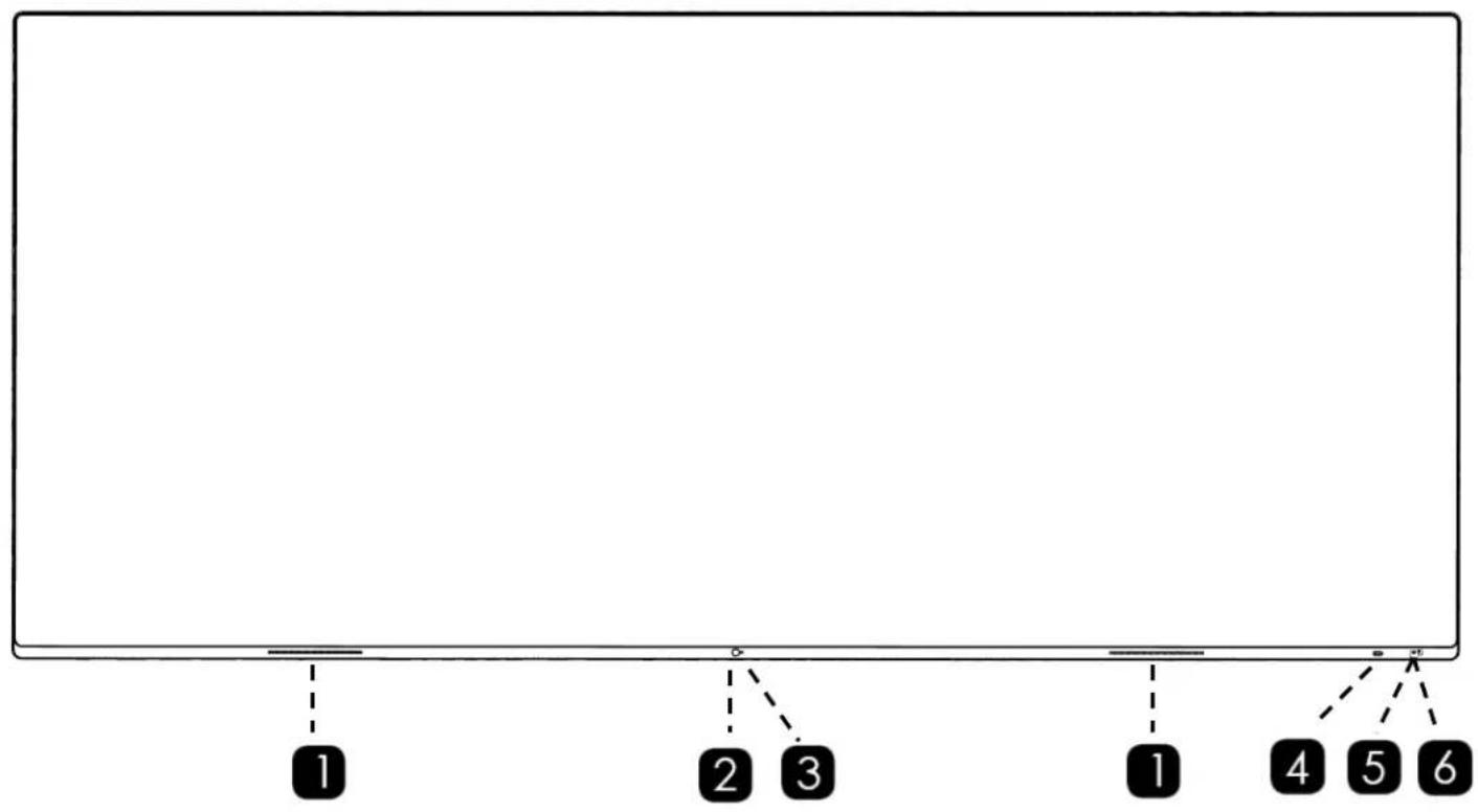
The following diagrams depict the front, side, and bottom panels of the display. The physical interface and connections are labeled, and then described in the tables that follow.
DISPLAY FRONT
flowchart
graph TD
    A["1"] --> B["2"]
    B --> C["3"]
    C --> D["4"]
    D --> E["5"]
    E --> F["6"]
DETAIL: FRONT PANEL MIDDLE SENSORS
DETAIL: FRONT PANEL POWER BUTTON & SENSORS
| 1 | Speaker Panel | 2x left and right speakers, 16W. |
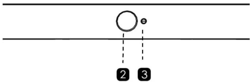
| 2 | Ambient Light Sensor | Calibrates screen brightness when Backlight>Auto is enabled. |
| 3 | Presence Sensor | Motion activated sensor |
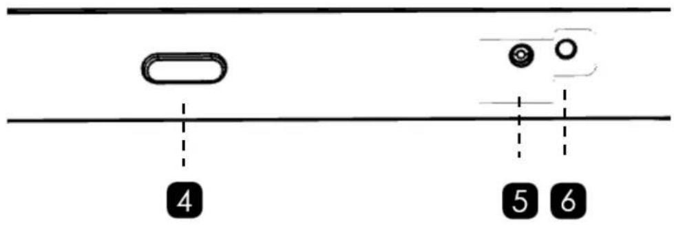
| 4 | Power Button | Toggles power for the display. |
| 5 | Ambient Environment Sensor | Temperature, humidity, CO2/VOCS. |
| 6 | IR Sensor | Receives signals from the Remote-Control Unit. |
BACK PANEL VIEW
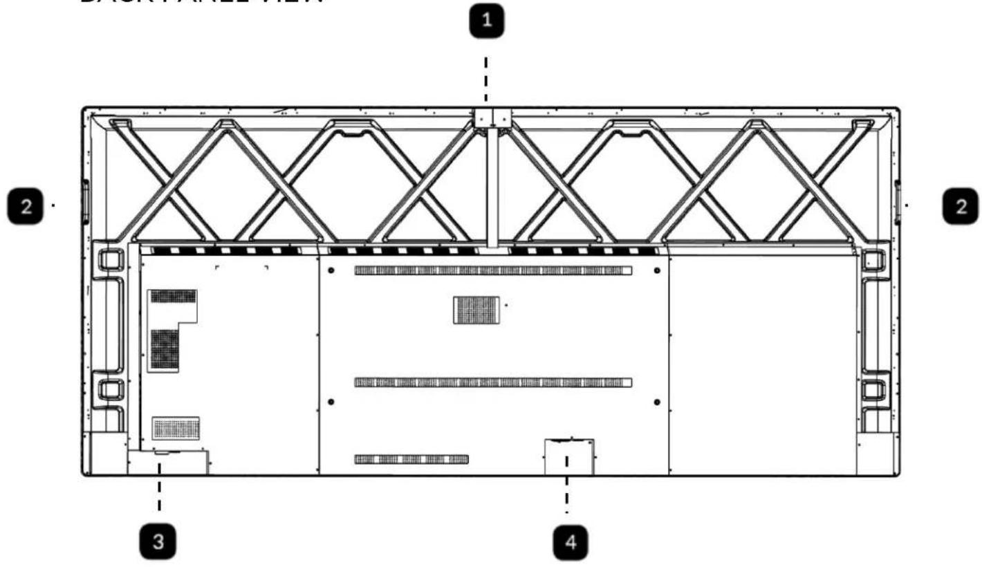
| 1 | USB Accessory Port | USB 3.0 Type A - HID input for mouse & keyboard accessories. |
| 2 | 2x Handles | Handles for carrying the display. |
| 3 | LAN/RS232 Panel | LAN, RS232, Service Port. |
| 4 | Power Panel | A/C Power Switch, Power Input, Power Output |
SIDE PANEL VIEW
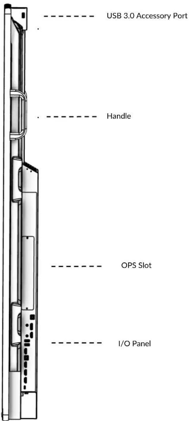
DETAIL: I/O PANEL

| 1 | USB Touch 1 | USB-B 2.0 - provides touch for DP & HDMI 1 |
| 2 | DP | DisplayPort 1.4 input that supports 5K@60 |
| 3 | HDMI 1 | HDMI 2.1 input that supports 5K@60 |
| 4 | 2x USB Accessory | USB 3.0 Type A - HID input for mouse & keyboard accessories |
| 5 | HDMI Out | HDCP compliant HDMI out - mirrors primary display. |
| 6 | USB Touch 2 | USB-B 2.0: USB Accessory HUB for AVL-1050-D. Provides touch for HDMI 2 & HDMI 3 for AVL-1050-T. |
| 7 | HDMI 2 | HDMI 2.0 input |
| 8 | HDMI 3 | HDMI 2.0 input |
| 9 | HDMI 4 | HDMI 2.0 input |
| 10 | Type-C | Supports video, touch, and 100W PD charging |
BOTTOM PANEL VIEW
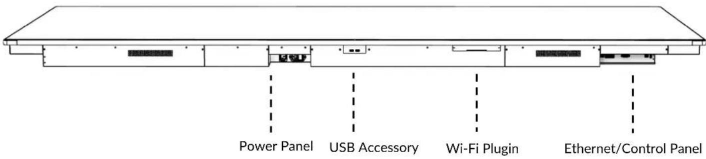
DETAIL: BOTTOM-PANEL WIFI, USB PORTS, AND POWER INPUT/OUTPUT

| 1 | Wi-Fi Module Plugin | Remove cover plate to access a USB-A plugin for the included WiFi module |
| 2 | 2x USB Accessory | USB 3.0 Type A - HID input for mouse & keyboard accessories |
| 3 | Power Switch and Input | A/C power switch & IEC C14 type power input |
| 4 | Power Output | IEC C14 type power output |
DETAIL: ETHERNET/CONTROL PANEL
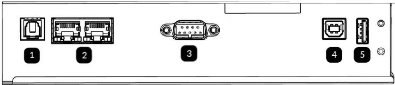
| 1 | SPDIF | Optical audio out for digital speakers or an audio receiver |
| 2 | LAN | 2x RJ-45 LAN input/output for internet or control system integration |
| 3 | RS232 | DB9 input, male, for control system integration |
| 4 | USB Touch 3 | USB-B 2.0 – provides touch for HDMI 4 |
| 5 | USB Service Port | Used for service-related tasks |
THE REMOTE CONTROL
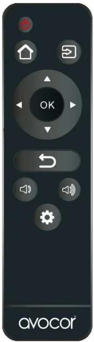
| Button | Description |
 | PowerTurns the display screen on and off |
 | HomeSwitch to Favorite Source input (Home by default). |
 | SourceSelects a media source |
 | Navigation arrowsNavigates through submenus and settings |
| OKConfirms the selection | |
 | ExitExits the OSD menu |
 | Volume downTurns down the volume |
 | Volume upTurns up the volume |
 | MenuOpens the OSD menu |
REMOTE CONTROL BATTERIES
To install batteries in the remote control:
- Press down the tab on the cover plate and pull the cover plate up.
- Insert the included batteries. Ensuring that the polarities correctly match the (+) and (-) markings inside the battery compartment.
- Insert the lower tab of the cover into the opening and press down the cover until it clicks in place.

Notes on Batteries
- Please only use approved AAA type batteries.
- Do not mix an old battery with a new one or different types of batteries.
- If you will not use the remote control for a long time, remove the batteries to avoid damage from battery leakage.
- Do not expose batteries to excessive heat such as from sunshine, fire, or the like.
- Don't recharge, heat, disassemble, short, or throw batteries into a fire.

Notes on Remote Control Operation
- Make sure that there is nothing obstructing the infrared beam between the remote control and the IR receiver on the display.
- If the effective range of the remote-control decreases, or it stops working, replace the batteries with new ones.
- The remote control may fail to operate if the infrared remote sensor is exposed to bright sunlight or fluorescent lighting.
- Ambient conditions may possibly impede the operation of the remote control. If this happens, point the remote control at the display, and repeat the operation.

Remote Control Sensor
- The effective area of the remote control includes the vertical distance within five metres in front of the display, and the area within an angle of 30 degrees from the vertical point to the left and the right.
INSTALLATION
⚠️ Please read the following precautions carefully before installing your new L-series display. Failure to comply may result in damage to the display and equipment, and may result in personal injury or death.
- DO NOT install the display in a high temperature environment or near any apparatus that produce heat.
- This may cause damage to the panel and equipment. It may also cause personal injury due to electrical shock resulting from overheating.
- DO NOT install the display in a high humidity environment or an environment where it can come into contact with water.
- This may cause damage to the panel and equipment. It may also cause personal injury due to electrical shock resulting from overheating.
• DO NOT overload outlets or cables beyond their electrical capacity.
- This may cause damage to the panel and equipment. It may also cause personal injury due to electrical shock resulting from overheating.
- DO NOT insert the power plug into an outlet rated outside the range of 100\~240V A/C.
- DO NOT insert the power plug into a damaged outlet.
- DO NOT use a worn or damaged A/C power cable.
- DO NOT use an improper or mismatched A/C power cable.
- DO NOT place the display on an unstable shelf or surface.
-
DO NOT place objects on the display as instructed below:
-
Do not cover the vents on the display.
- Do not allow liquid or small particles to enter the vents or other parts of the display.
- Do not put heavy objects on the display.
- Please allow room between the wall and the display panel to maintain proper ventilation and avoid overheating.
- Make sure you use the handles on the back of the display while lifting or moving the display, to avoid touching the front panel during the move.
The L-Series 105" display requires at least 3 to 4 people to handle, unpack, carry, and mount safely.
Before installing, please make sure the wall is strong enough to hold the necessary weight of the display and the mount.
AMBIENT CONSIDERATIONS
Environmental and ambient factors play a considerable role in determining your viewing experience and the functional operation of the display. Make sure to follow these guidelines carefully to get the most out of your display.
AMBIENT LIGHT
For the best viewing experience, make sure to minimize or remove light sources directed at the screen, especially sunlight.
Any direct light may make images on the screen appear washed out and less vibrant, and direct sunlight may even affect touch control operation.
AMBIENT TEMPERATURE
Maintain the ambient temperature of the room at a consistent level. This will ensure that the display continues to operate smoothly.
Do not place the display near heat sources or air conditioning vents, and do not operate or store the display in temperatures above 40 degrees Celsius (104 degrees Fahrenheit).
VENTILATION
The display should maintain a proper operating temperature provided that the ambient temperature is not too high, and that the vents on the display have enough room to disperse any heat emanating from the display.
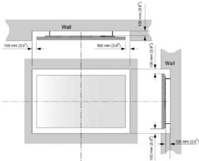
Do not block the vents on the display! Leave a space of about 4 inches between all sides of the display and surrounding walls or objects, as shown in the figure, below.
MOUNTING THE DISPLAY
The L-series requires a 1000x400mm compatible VESA mounting bracket. You can use any compatible mounting solution that supports both the VESA and weight of the display, but a compatible wall mount is included with your new display.

PRECAUTION
Please review the following items prior to mounting your L-series display. Failure to comply may result in damage to the display and equipment, and may result in personal injury or death.
• Always enlist the help of professional integrators to mount and install your display.
• 3-4 people are required to handle the L-series display.
- Ensure that your mounting mechanism is rated to hold the weight of your display (\~220lbs).
- The wall mounted surface must be capable of supporting a redundant weight factor of 3x the weight of the display or be reinforced to support a 3x redundant weight factor.
- Make sure the tilt degree of the display does not exceed 2^ .
- When using third-party equipment, only use dealer or manufacturer approved mounting kits.
INSTALLATION VIA THE INCLUDED WALL MOUNT
Your L-series display come with a compatible wall mount, included in the box, installation hardware, and two VESA hooks already pre-installed on the VESA pattern of the display. The following instructions will guide you through the installation process.
HARDWARE INCLUDED
- 1x Wall mount plate
natural_image
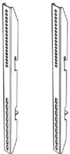
Top-down architectural rendering of a three-panel wall-mounted room with windows and doorways (no text or symbols)- 2x Wall mount adapter brackets (pre-installed on display)
natural_image
Two identical line drawings of a rectangular electronic device with internal components and mounting holes (no text or symbols)• (e) 10x Washers
• (f) 10x Philips lag-bolt mounting screws
• (g) 10x Concrete anchors
GENERAL OVERVIEW:
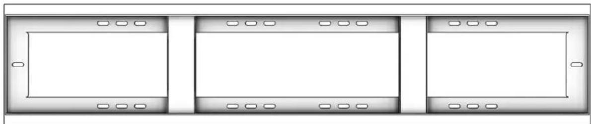
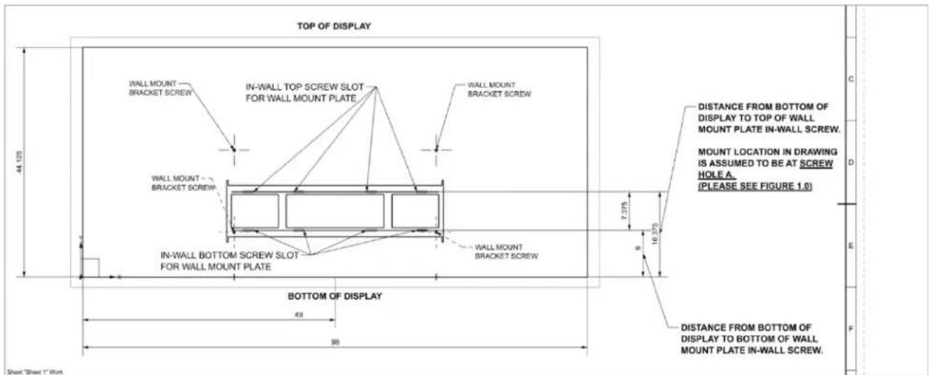
The diagram above features the back of the Avocor L series 105" display along with the box-provided wall mount projected over it. For a more detailed view, click HERE. It is important to note that consumers are able to change the locations of the wall mount bracket itself so that the display can either sit higher or lower. The top screw hole of the wall mount bracket (pictured below) directly influences this. Ex: Hole A sets display the tallest, while hole B sets display the shortest. See Figures 1.0 and 1.1 for more details on where best to position your mount bracket / wall mount plate.
SETTING UP YOUR WALL MOUNT PLATE:
Once you have installed the wall mount bracket to the back of the AVL-1050 display, the next step is to set up the wall mount plate for installation. The wall mount plate must be installed into a wall with proper studs in order to support the weight of the display. Additionally, use the above-mentioned Figure 1.0 chart to find the location of your in-wall screws from the TOP/BOTTOM of the display in order to install the wall mount plate. Simply measure from the top/bottom of where you would like your display to be located at and measure to the in-wall screw locations for the wall mount plate. Additionally, in Figure 1.1 there are suggested heights for mounting the AVL-1050 display that work for most setups.

| Figure 1.0 | Distance from bottom of AVL-1050 to wall mount plate in-wall top screw | Distance from bottom of AVL-1050 to wall mount plate in-wall bottom screw | |||
| Top of Wall Mount Bracket Screw Position | A | 16 3/8 in | 41.593 cm | 9 in | 22.860 cm |
| B | 22 5/8 in | 57.468 cm | 15 1/4 in | 38.735 cm | |
| Be sure to add the floor → bottom of display height to the values presented for wall mount bracket holes A and B for best installation. | |||||
| Figure 1.1 | Suggested Wall Mounting Height | ||||
| Distance from floor to wall mount plate in-wall top screw | Distance from floor to wall mount plate in-wall bottom screw | ||||
| Top of Wall Mount Bracket Screw Position | A | 55 3/8 in | 140.653 | 48 in | 121.920 cm |
| B | 61 5/8 in | 156.528 | 54 1/4 in | 137.795 cm | |
| Mounting height reference is set 39" from floor + length from bottom of display to in-wall screws for wall mount plate | |||||
WI-FI MODULE INSTALLATION
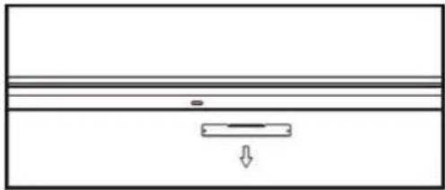
- Take off the Cover using a Philips screwdriver.
natural_image
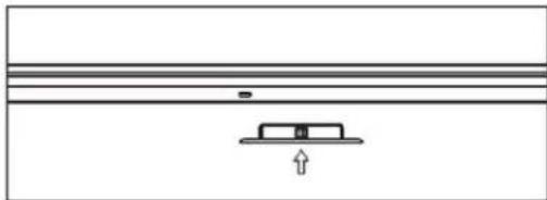
Pure diagram of a horizontal beam with a downward load, no text or symbols present- Insert the Wi-Fi module fully into the Avocor L-series display along the direction of the arrow.
natural_image
Simple line drawing of a rectangular object with a downward arrow and a small rectangular base, no text or symbols present.- Complete assembly.
natural_image
Simple horizontal line diagram with no text, numbers, or symbolsOPS MODULE INSTALLATION
-
Ensure that the display is turned off.
-
Use a Philips screwdriver to unscrew the OPS slot shield on the display input panel. Do not lose the screws that are removed.
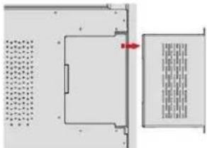
natural_image
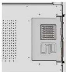
Pure electrical circuit lines without any symbols- Install the OPS module by sliding it into the OPS slot until you hear a click, indicating the module is securely inserted. When using an Avocor OPS PC, the fan should be visible.
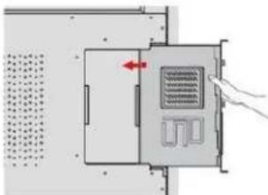
natural_image
Diagram of a device with a red arrow pointing to a component, showing no readable text or symbols.- Secure the OPS module in position by screwing it onto the display input panel using the screws that were removed earlier.
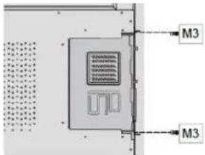
- Ensure the installation is complete before turning on the power.
natural_image
Pure electrical circuit lines without any symbols- Turn on the display. When using an Avocor OPS PC you should see a green light on the side of the OPS, this will indicate that the OPS PC is switched on and operational.

When installing or de-installing an OPS PC, the display must be switched off. If the display is on when performing the installation or deinstallation of the OPS PC, this could cause damage to either the display or OPS PC invalidating the warranty for both.

The L-series supports OPS modules that follow the OPS standard.
OPERATION
THE HOME SCREEN
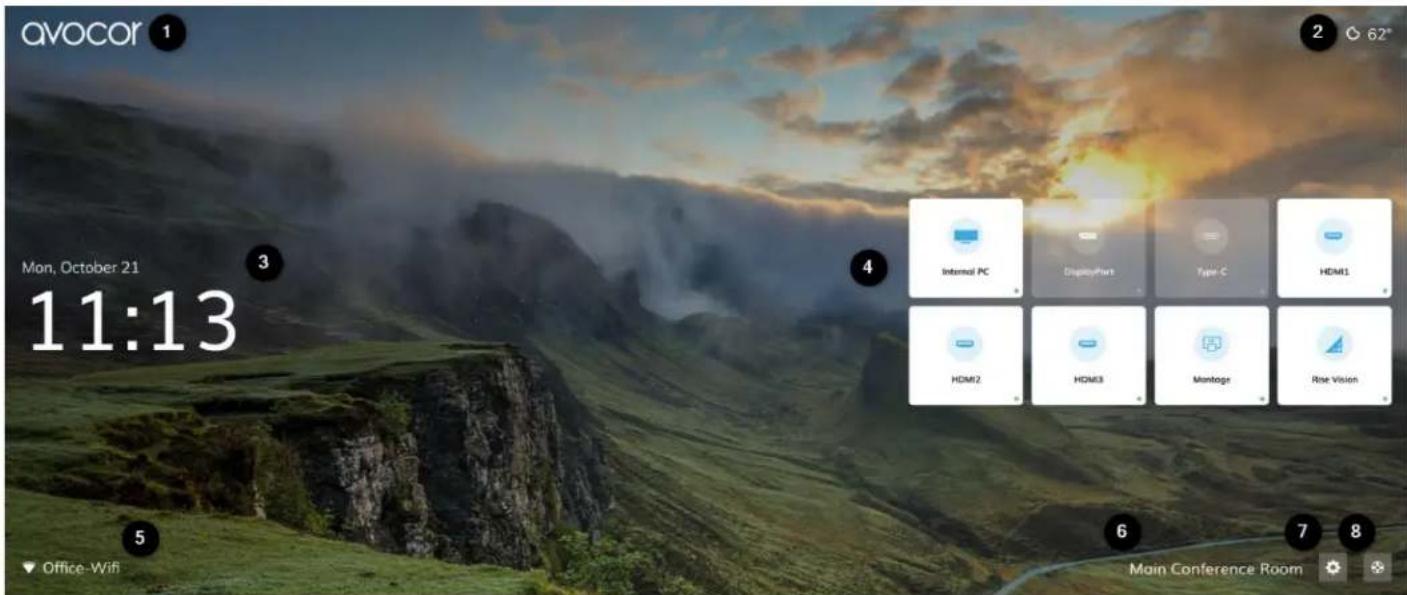
1 Avocor logo: can be toggle on/off, see Display Settings.
2 Weather icon and temperature: powered by OpenWeather® API, shows the current weather conditions and temperature for the Location selected in Location & Time. Network connection is required.
3 Date and time: configurable in Location & Time. Auto-date and time requires a network connection.
4 Source tiles: white, highlighted sources are indicative of active source connections; touch an active source, or highlight via the RCU, to switch to it. Source names and tile configuration can be changed in Input.
5 Network icon and network name: Indicates network name and connection type. Configurable in Network.

- Ethernet/LAN connected

- Wi-Fi connected
6 Display name: configurable in Display Settings.
7 UiQ Settings: touch this icon or select it via the RCU to open UiQ Settings. You can also press the Settings button on the RCU to access this menu at any time.
8 Support: submit a review and get help with your display; see Support for more information.
UIQ SETTINGS
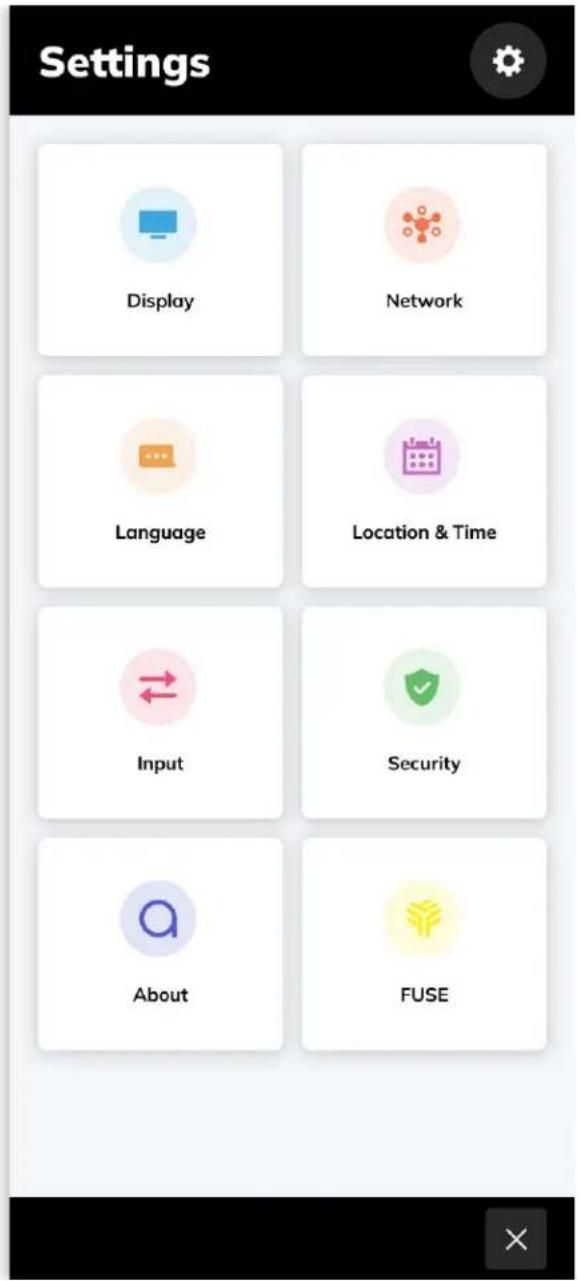
➢ Display: Avocor Logo, Name, Wallpaper Energy Saving, Picture, Audio.
➢ Network: Status, LAN, Wi-Fi, Wake On LAN, LAN USB.
Language: English, Deutsch, Español, Français, Italiano, Nederlands.
Location & Time: Location, Auto Date & Time, Set Date, Set Time, Use 24-Hour Time, Date Format, Weather>Unit.
Input: Favorite Source, Starting Source, Timeout Source, Auto Detect New Input, Source Preview, Rename Sources, Advanced Settings.
Security: Require Passkey, Set Passkey, Lock Front Button.
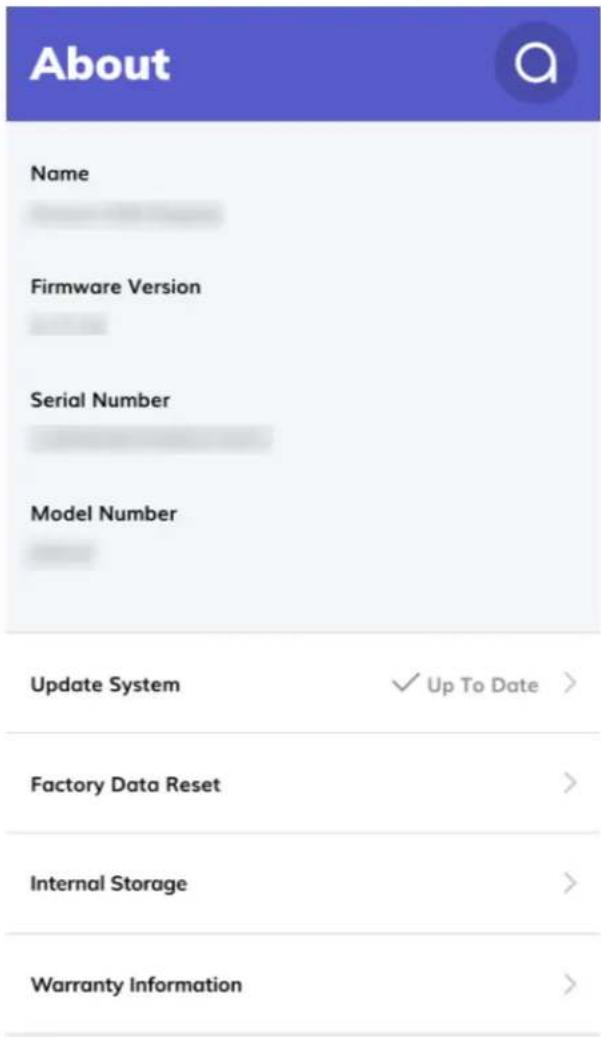
About: Display Information, Update System, Factory Data Reset, Internal Storage, Warranty Information.
➢ Fuse: Register Device to Fuse, Status, Device Name, Space Name, Claimed By.
DISPLAY SETTINGS
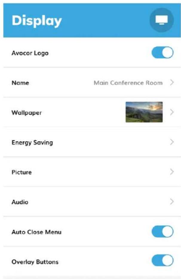
Avocor Logo: Toggles the presence of the Avocor logo on the Home Screen.
Name: Changes the name assigned to the display, which is visible on the Home Screen.
Wallpaper: changes the background image of the Home Screen.
Energy Saving: settings that affect power and sleep.
➢ Picture: adjust image properties.
Audio: adjust sound properties.
Auto Close Menu: toggle on to enable the UiQ Settings menu to close after a 60-second idle period.
➢ Overlay Buttons: toggle on/off the touch Overlay Buttons (AVL-1050-T only).
Wallpaper
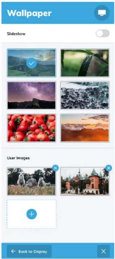
Slideshow: toggle on, and the Home Screen background will cycle through all selected images.
Default Images: high definition 21:9 images preloaded on the L-series display; touch the desired image(s), or highlight and select with the RCU, to set as the Home Screen background.
User Images: upload and select custom images for the Home Screen background; see custom wallpapers for further instruction.
Custom Wallpapers
Follow these instructions to upload your own wallpaper images. Note: Only 1920x1080 images or higher are supported.
- Take a USB flash drive
- Open the USB flash drive's file directory on a computer.
- Create a new folder with the name WALLPAPER.
-
Save all images you want to use into the WALLPAPER folder.
-
On the Display navigate to Settings>Display>Wallpaper.
-
Under User Images, touch the blank tile containing the "+" symbol (see image).
-
Plug your flash drive into the USB service port, you will then be able to select compatible images to upload.
Energy Saving
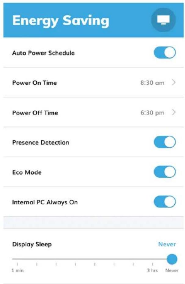
➢ Auto Power Schedule: toggle on to enable automatic power scheduling.
Power On Time: select the time and days of the week to automatically power on the display.
Power Off Time: select the time and days of the week to automatically power off the display.
➢ Presence Detection: toggle on and the display will wake from sleep at the detection of movement.
Eco Mode: toggles on to enable an Energy Star® compliant power state for the display; permanently disabled once registered to Fuse.
Internal PC Always On: toggle on to keep the OPS power on, even when the display is in standby; permanently enabled once registered to Fuse.
➢ Display Sleep: use this slider to set an idle timer between 1 minute and 3 hours of no interaction before the display goes to sleep
NETWORK SETTINGS
Network  | |
| Status | Cable Connected |
| LAN | Static > |
| Wi-Fi | Office-Wifi > |
| Wake On LAN | |
| LAN USB | |
LANGUAGE SETTINGS
| Language |  |
| Language | English (US) > |
➢ Status: shows network connection status.
LAN: set a "Static IP" or "DHCP," check LAN configuration, view ethernet MAC address.
Wi-Fi: configure Wi-Fi settings, view Wi-Fi MAC address.
Wake on LAN: toggle "Wake On LAN".
LAN USB: toggle to pass network connection through the display's USB HUB
Language: Set the language for the display's user interface.
○ Currently supported languages:
- English
- Deutsch
- Español
- Français
- Italiano
■ Nederlands
LOCATION & TIME SETTINGS
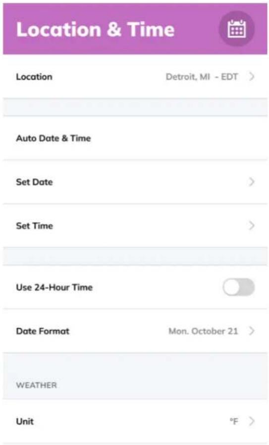
➢ Location: set location dependency for Auto Date & Time and Weather information.
Auto Date & Time: toggle Auto Date & Time On or Off (if On internet connection required).
Set Date: manually set the date.
Set Time: manually set the time.
➢ Use 24 Hour Time: toggle 24-hour clock.
Date Format: set date format.
Unit: set unit for measure of temperature (°F, °C)
INPUT SETTINGS
| Input | |
| Favorite Source | Home Screen > |
| Starting Source | Home Screen > |
| Timeout Source | Rise Vision > |
| Auto Detect New Input | |
| Source Preview | |
| Rename Sources | > |
| Advanced Settings | > |
Favorite Source: sets the source tied to the Home button on the remote and Overlay Buttons.
Starting Source: sets the default source shown when the display powers on.
Timeout Source: set a source to automatically switch to after a set idle period.
Auto Detect New Input: toggle to enable the display to automatically switch to a new active source connection.
Source Preview: toggle on to generate an image preview upon selecting a Source Tile from the Home Screen.
Rename Sources: set custom names for sources.
Advanced Settings: toggle Wake on Input and view detailed video signal information.
SECURITY
ABOUT
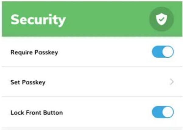
Require Passkey: toggle to require a passkey to access UiQ Settings.
Set Passkey: set the passkey.
Lock Front Keys: lock the front panel buttons on the displa
Name: personalized display name, assigned when claimed in Fuse.
➢ Firmware Version: shows the display's current firmware version.
Serial Number: unique product identifier.
➢ Model Number: model ID for the display.
Update System: when status changes to "Update Available!" select this menu to begin the Update System process.
➢ Factory Data Reset: restore factory defaults for the display.
Internal Storage: shows the display's remaining internal storage space.
Warranty Information: shows the display's remaining warranty.
Update System Firmware
Update System

New System Version
5.0.2
New Firmware Version
HHT_U6H0L13T5M0005NYENEN_MS828.15.A75_V1.3.3_20180621.144018_785b2ec
Release Notes
- Improved EDID compatibility.
- Fixed Wake on Input when using DisplayPort.
- Improved input switching time.
- UI updates.
- Various bug fixes.
New System Version: numerical designation for the new update.
New Firmware Version: expanded firmware version number.
Release Notes: changes and fixes present in the new version will be listed here.
Download & Apply Update

USB Update

Download & Apply Update: select this to begin the update process.
USB Update: select this to update via USB.
EXTERNAL CONTROL
This section provides information on external control setup for room control systems. RS232 and LAN control options are supported.
RS232 CONNECTION AND PORT CONFIGURATION
Connect your control system or PC to the RS232 input of the display via a 9-pin straight-through connector cable and set the baud rate to 9600 on your controller device.
Connect your network, control system, or PC to the display's LAN port via a CAT5 cable. The display must be connected to the network and must have a valid IP address. Configure your control system to run through Port 4664.
COMMAND AND RESPONSE FORMAT
Any commands sent from an automation/control system or PC to an Avocor display must have the following format:
[byte1] [byte2] [byte3] [byte4] [byte5] [byte6] [byte7] [byte8] [byte9]
- [byte1] indicates the start of the command data (always 3A).
- [byte2] & [byte3] are always 30 & 31, respectively; calls for the machine ID, 1.
• [byte4] defines the command type: - 53 = SET command
- 47 = GET command
- [byte5] is the parameter (Param) setting for the command.
- [byte6], [byte7], [byte 8] are variable, data inputs.
- [byte9] indicates the end of the command string, always 0D.
SERIAL COMMAND LIST
| Event | Param. | Value | Command |
| Power | 30 | 000 : backlight off | 3A 30 31 53 30 30 30 30 0d |
| 001 : backlight on | 3A 30 31 53 30 30 30 31 0d | ||
| 002 : power off | 3A 30 31 53 30 30 30 32 0d | ||
| 003 : power on | 3A 30 31 53 30 30 30 33 0d | ||
| Treble | 31 | -xx: -5~0 | 3A 30 31 53 31 2D 30 33 0d |
| +xx: 0~5 | 3A 30 31 53 31 2B 30 33 0d | ||
| Bass | 32 | -xx: -5~0 | 3A 30 31 53 32 2D 30 35 0d |
| +xx: 0~5 | 3A 30 31 53 32 2B 30 35 0d | ||
| Balance | 33 | -xx: -50~0 | 3A 30 31 53 33 2D 35 30 0d |
| +xx: 0~50 | 3A 30 31 53 33 2B 32 30 0d | ||
| Contrast | 34 | 000 ~ 100 | 3A 30 31 53 34 30 35 30 0d |
| Brightness | 35 | 000 ~ 100 | 3A 30 31 53 35 30 35 30 0d |
| Sharpness | 36 | 000 ~ 100 | 3A 30 31 53 36 30 31 30 0d |
| Sound Mode | 37 | 000 : Movie | 3A 30 31 53 37 30 30 30 0d |
| 001 : Standard | 3A 30 31 53 37 30 30 31 0d | ||
| 002 : Custom | 3A 30 31 53 37 30 30 32 0d | ||
| 003 : Classroom | 3A 30 31 53 37 30 30 33 0d | ||
| 004 : Meeting | 3A 30 31 53 37 30 30 34 0d | ||
| Volume | 38 | 000 ~ 100 | 3A 30 31 53 38 30 35 30 0d |
| Mute | 39 | 000: Off | 3A 30 31 53 39 30 30 30 0d |
| 001: On | 3A 30 31 53 39 30 30 31 0d | ||
| Video Source | 3A | 000 : VGA | 3A 30 31 53 3A 30 30 30 0d |
| 001 : HDMI1 | 3A 30 31 53 3A 30 30 31 0d | ||
| 002: HDMI2 | 3A 30 31 53 3A 30 30 32 0d | ||
| 003 : AV | 3A 30 31 53 3A 30 30 33 0d | ||
| 022 : HDMI4 | 3A 30 31 53 3A 30 32 32 0d | ||
| 021 : HDMI3 | 3A 30 31 53 3A 30 32 31 0d | ||
| 031 : VGA2 | 3A 30 31 53 3A 30 33 31 0d | ||
| 032 : VGA3 | 3A 30 31 53 3A 30 33 32 0d | ||
| 051 : ATV | 3A 30 31 53 3A 30 35 31 0d | ||
| 101 : android | 3A 30 31 53 3A 31 30 31 0d | ||
| 103 : Slot in PC | 3A 30 31 53 3A 31 30 33 0d | ||
| 007 : Display Port | 3A 30 31 53 3A 30 30 37 0D | ||
| 102 : android + | 3A 30 31 53 3A 31 30 32 0D | ||
| 104 : Type-C1 | 3A 30 31 53 3A 31 30 34 0D | ||
| 105 : Type-C2 | 3A 30 31 53 3A 31 30 35 0D | ||
| 106: DTV | 3A 30 31 53 3A 31 30 36 0D | ||
| 107 : YPbpr | 3A 30 31 53 3A 31 30 37 0D | ||
| Aspect Ratio | 3B | 000 : 16:9 | 3A 30 31 53 3B 30 30 30 0d |
| 001 : 4:3 | 3A 30 31 53 3B 30 30 31 0d | ||
| 002 : PTP | 3A 30 31 53 3B 30 30 32 0d | ||
| Language | 3C | 000: English | 3A 30 31 53 3C 30 30 30 0d |
| 001: Français | 3A 30 31 53 3C 30 30 31 0d | ||
| 002: Español | 3A 30 31 53 3C 30 30 32 0d | ||
| 006: German | 3A 30 31 53 3C 30 30 36 0d | ||
| 007: Dutch | 3A 30 31 53 3C 30 30 37 0d | ||
| 011: Danish | 3A 30 31 53 3C 30 31 31 0d | ||
| 013: Italian | 3A 30 31 53 3C 30 31 33 0d | ||
| Picture Mode | 3D | 000 : standard | 3A 30 31 53 3D 30 30 30 0d |
| 001 : bright | 3A 30 31 53 3D 30 30 31 0d | ||
| 002 : soft | 3A 30 31 53 3D 30 30 32 0d | ||
| 003 : customer | 3A 30 31 53 3D 30 30 33 0d | ||
| Hue (Color) | 3E | 000 ~ 100 | 3A 30 31 53 3E 30 33 30 0d |
| Backlight | 3F | 000 ~ 100 | 3A 30 31 53 3F 30 35 30 0d |
| Color Temp | 40 | 000 : Cool | 3A 30 31 53 40 30 30 30 0d |
| 001 : Standard | 3A 30 31 53 40 30 30 31 0d | ||
| 002 : Warm | 3A 30 31 53 40 30 30 32 0d | ||
| Remote control command | 41 | 000 : Vol + | 3A 30 31 53 41 30 30 30 0d |
| 001 : Vol - | 3A 30 31 53 41 30 30 31 0d | ||
| 010 : Up | 3A 30 31 53 41 30 31 30 0d | ||
| 011 : Down | 3A 30 31 53 41 30 31 31 0d | ||
| 012 : Left | 3A 30 31 53 41 30 31 32 0d | ||
| 013 : Right | 3A 30 31 53 41 30 31 33 0d | ||
| 014 : Enter | 3A 30 31 53 41 30 31 34 0d | ||
| 020 : Menu | 3A 30 31 53 41 30 32 30 0d | ||
| 021 : Input | 3A 30 31 53 41 30 32 31 0d | ||
| 022 : Back/Exit | 3A 30 31 53 41 30 32 32 0d | ||
| 031 : Blank | 3A 30 31 53 41 30 33 31 0d | ||
| 032 : Freeze | 3A 30 31 53 41 30 33 32 0d | ||
| 033 : Mute | 3A 30 31 53 41 30 33 33 0d | ||
| 034 : Home | 3A 30 31 53 41 30 33 34 0d | ||
| IR | 42 | 000: Enable | 3A 30 31 53 42 30 30 30 0d |
| 001: Disable | 3A 30 31 53 42 30 30 31 0d | ||
| Speaker | 43 | 000 : off | 3A 30 31 53 43 30 30 30 0d |
| 001 : on | 3A 30 31 53 43 30 30 31 0d | ||
| Touch | 44 | 000 : off | 3A 30 31 53 44 30 30 30 0d |
| 001 : on | 3A 30 31 53 44 30 30 31 0d | ||
| Screen | 45 | 000 : off | 3A 30 31 53 45 30 30 30 0d |
| 001 : on | 3A 30 31 53 45 30 30 31 0d | ||
| No signal power off | 46 | 000: off | 3A 30 31 53 46 30 30 30 0d |
| 001 : 1 minute | 3A 30 31 53 46 30 30 31 0d | ||
| 003 : 3 minutes | 3A 30 31 53 46 30 30 33 0d | ||
| 005 : 5 minutes | 3A 30 31 53 46 30 30 35 0d | ||
| 010 : 10 minutes | 3A 30 31 53 46 30 31 30 0d | ||
| 015 : 15 minutes | 3A 30 31 53 46 30 31 35 0d | ||
| 030 : 30 minutes | 3A 30 31 53 46 30 33 30 0d | ||
| 045 : 45 minutes | 3A 30 31 53 46 30 34 35 0d | ||
| 060 : 60 minutes | 3A 30 31 53 46 30 36 30 0d |
AVOCOR: ONE-YEAR LIMITED WARRANTY
Congratulations on purchasing an Avocor L-series display! Avocor is pleased to extend the following limited warranty to the original end-user customer of our products.
COVERAGE
Avocor warrants to the first end user customer that the product, when shipped in its original container, will be free from defective workmanship and materials, and agrees that it will, for a period of one (1) year from the date of purchase, repair or replace the defective product or part thereof, at Avocor's discretion, with a new or equivalent at no charge to the customer. Advanced Field Replacement (AFR) service is included as part of this warranty. Except as specified herein, this warranty covers all defects in material or workmanship in the product. AVOCOR'S LIABILITY FOR ANY DEFECTIVE PRODUCT IS LIMITED TO THE REPAIR OR REPLACEMENT OF THE PRODUCT AT AVOCOR's DISCRETION. REPLACEMENT PARTS OR PRODUCTS MAY BE NEW OR 'LIKE NEW' UNDER THE CONDITIONS SPECIFIED BELOW. All parts or products removed under this warranty become the property of Avocor.
The replacement part or product is warranted for the remainder of the original limited warranty period or thirty days from shipment, whichever is longer.
LIMITATIONS ON WARRANTY COVERAGE, DURATION, AND SERVICES MAY SOMETIMES VARY BASED ON THE LAWS OF SPECIFIC REGIONS, STATES, AND COUNTRIES. THIS LIMITED WARRANTY GIVES YOU SPECIFIC LEGAL RIGHTS, AND YOU MAY HAVE OTHER RIGHTS WHICH VARY FROM JURISDICITON TO JURISDICTION.
EXCLUSIONS
This warranty does not apply to any cosmetic or consumable items of the Product or if the serial number or model number affixed to the Product has been removed, defaced, changed, altered or tampered with.
This warranty does not cover installation, signal reception problems, potential incompatibility with peripheral devices, or acts of nature. Avocor does not warrant nor shall it be liable for Products which have been subject to abuse, including, but not limited to, improper voltage, accident, misuse, negligence, lack of reasonable care, alteration, modification, tampering, improper installation, shipping damage, operation or maintenance or any damages or defects caused by repairs or attempted repairs performed by anyone other than Avocor personnel or an Avocor-authorized servicer. This warranty also excludes any damage to product glass due to pressure, abrasion, scratches, or actions otherwise
beyond normal operation of the product that would cause screen mura and image retention. Please refer to Avocor's pixel policy for warranty guidelines on pixel related issues.
CONCEALED DAMAGE
It is the customer's responsibility to inspect new product(s) at the time of delivery.
If packaging is found damaged at the time of delivery, the Customer should refuse delivery and note on the delivery receipt the product and details pertaining to damage. The Customer may accept packages with minor damage but must take note of product details and damage on the delivery receipt.
If patent or obvious physical damage is detected after delivery is accepted and a “clean” or unmarked delivery receipt was returned, it is the customer’s responsibility to file an insurance claim to the shipping provider according to the requirements set forth in the shipping provider's policy.
If the product packaging is clean and undamaged, but patent or obvious physical damage is found on the product, the customer must report the damages to their product distributor, shipper, or seller, within the policy guidelines of the distributor, shipper, or seller.
If freight was arranged by Avocor, and patent or obvious physical damage to the packaging is not detected but found on the product or product accessories upon inspecting the product, the customer must report the damages to Avocor within 10 calendar days after the delivery date to receive warranty services.
CUSTOMER DATA
If the customer's product is capable of storing software programs, data, and other information, it is the customer's responsibility to protect its contents against operational failure. It is also the customer's responsibility to keep a separate backup of the contents and remove all personal information and disable security passwords prior to delivering a product for warranty service. ANY PERSONAL CONTENT WILL BE DELETED AND STORAGE MEDIA WILL BE REFORMATTED IN THE COURSE OF WARRANTY SERVICE.
AVOCOR SHALL NOT BE LIABLE, OR IN ANY WAY RESPONSIBLE, FOR ANY INCIDENTAL OR CONSEQUENTIAL ECONOMIC OR PROPERTY DAMAGE. SOME REGIONS DO NOT ALLOW LIMITS ON WARRANTIES OR ON REMEDIES FOR BREACH IN CERTAIN TRANSACTIONS; IN SUCH REGIONS, THE LIMITS HEREIN MAY NOT APPLY. THIS WARRANTY IS IN LIEU OF ALL OTHER WARRANTIES, EXPRESSED OR IMPLIED. AVOCOR DISCLAIMS ALL OTHER WARRANTIES, EXPRESSED OR IMPLIED, INCLUDING, BUT NOT LIMITED TO, IMPLIED WARRANTIES OF NON-INFRINGEMENT, MERCHANTABILITY, AND FITNESS FOR A PARTICULAR PURPOSE.
SERVICES
Technical Support: The Customer must contact Avocor Technical Support, via email at service@avocor.com in order to initiate an RMA or another warranty service. Customer agrees to cooperate with Avocor: (A) to notify Avocor promptly of any defect, error or Hardware Product malfunction and to submit to Avocor such information that Avocor may reasonably require to reproduce the error or Hardware Product malfunction was discovered; (B) to follow Avocor's guidelines to troubleshoot reported faults on the defective product(s); (C) to install, if requested by Avocor and within Customer security guidelines, a network connection that will be made available to Avocor for the purpose of resolving problems, reviewing Customer use of software, or for any other reasonable purpose; (D) to have a certified technician repair or replace defective parts under Avocor's guidance; (E) to notify Avocor of any additional hardware or software not purchased from Avocor that may be used in conjunction with the Hardware Product.
Onsite Repair: If Avocor deems the Product repairable, it will, at its discretion, send a technical support representative and/or technician to provide onsite repair or replacement service for any repairable or replaceable parts. Customer may be asked to provide access to, and to assist in the handling of, the Product, as deemed necessary by Avocor, under the instruction of the field representative or technician.
Advance Field Replacement (AFR): Avocor will ship a like-new or refurbished replacement product to the customer, at its discretion, if the product defect is determined to be unrepairable. The Customer must provide the display model and serial number and will be asked to provide contact details for the shipment. Upon approval, Avocor will ship the replacement product to the customer's site.
AFR Guidelines: At the time of the new product's arrival to the customer, it is the customer's responsibility to facilitate the deinstallation of the defective product, installation of the replacement product, and packing of the defective product in either its original packaging or the packaging of the replacement, and then send the defective back with the same driver that delivered the replacement product on that same day. If the customer is not able to perform the same-day swap they will incur the cost of freight. Additionally, if the product is not returned within 15 business days, the customer will be invoiced in full for the replacement product.
SHIPMENTS TO CERTAIN INTERNATIONAL LOCATIONS MAY NOT BE SUBJECT TO THE ABOVE AFR GUIDELINES. CONTACT SUPPORT FOR FURTHER DETAILS.
Defective on Arrival (DOA): If the Product is determined by Avocor to be defective within the first 90 days of the initial purchase by the Customer, it is deemed Defective on Arrival (DOA). In the case of a DOA, the Customer will be provided a brand-new equivalent Product. In the case that an RMA is issued after the 90 DOA period, the defective product will be replaced with a refurbished "like new" equivalent product, if available.
L-SERIES USER MANUAL | 44
Repair with Expired Warranty: Avocor offers repair services, at cost to the Customer based on time and materials, for products with expired warranty. Customer will be responsible for all shipment costs.
For more information, please email at service@avocor.com.
- L-SERIES USER MANUAL
- TABLE OF CONTENTS
- Compliance Information ....3
- Introduction 5
- What's in the Box? 7
- Specifications....8
- The display, at a glance 10
- The Remote Control 17
- Installation.... 19
- L-SERIES USER MANUAL | 2
- COMPLIANCE INFORMATION
- DECLARATION OF CONFORMITY
- CAUTION
- INDUSTRY CANADA (ICES-003)
- PRODUCT DISPOSAL
- DISPOSAL OF OLD ELECTRICAL AND ELECTRONIC EQUIPMENT
- INTRODUCTION
- ABOUT THIS MANUAL
- TEXTUAL CONVENTIONS
- GRAPHIC CONVENTIONS
- WHAT'S IN THE BOX?
- THE DISPLAY, AT A GLANCE
- BOTTOM PANEL VIEW
- THE REMOTE CONTROL
- REMOTE CONTROL BATTERIES
- Notes on Batteries
- Notes on Remote Control Operation
- Remote Control Sensor
- INSTALLATION
- AMBIENT CONSIDERATIONS
- AMBIENT LIGHT
- AMBIENT TEMPERATURE
- VENTILATION
- MOUNTING THE DISPLAY
- PRECAUTION
- INSTALLATION VIA THE INCLUDED WALL MOUNT
- HARDWARE INCLUDED
- GENERAL OVERVIEW:
- SETTING UP YOUR WALL MOUNT PLATE:
- WI-FI MODULE INSTALLATION
- OPS MODULE INSTALLATION
- OPERATION
- THE HOME SCREEN
- UIQ SETTINGS
- DISPLAY SETTINGS
- Wallpaper
- Custom Wallpapers
- Energy Saving
- NETWORK SETTINGS
- LANGUAGE SETTINGS
- LOCATION & TIME SETTINGS
- INPUT SETTINGS
- SECURITY
- ABOUT
- Update System Firmware
- Update System
- New System Version
- New Firmware Version
- Release Notes
- EXTERNAL CONTROL
- RS232 CONNECTION AND PORT CONFIGURATION
- COMMAND AND RESPONSE FORMAT
- AVOCOR: ONE-YEAR LIMITED WARRANTY
- COVERAGE
- EXCLUSIONS
- CONCEALED DAMAGE
- CUSTOMER DATA
- SERVICES
- SHIPMENTS TO CERTAIN INTERNATIONAL LOCATIONS MAY NOT BE SUBJECT TO THE ABOVE AFR GUIDELINES. CONTACT SUPPORT FOR FURTHER DETAILS.
Brand : Avocor
Model : AVL-1050-D
Category : Monitor