MA 250.4 - Blender Ashly - Free user manual and instructions
Find the device manual for free MA 250.4 Ashly in PDF.


| Type of Product | Professional Power Amplifier |
| Model | MA 250.4 |
| Number of Channels | 4 |
| Output Power per Channel (Low-Z) | 250W RMS into 2/4/8 ohms |
| Output Power per Channel (Constant Voltage) | 250W RMS into 25V, 70V, or 100V lines |
| Bridged Output Power (per pair) | 500W RMS into 4/8 ohms |
| Power Sharing | Intelligent power sharing across 4-channel groups, up to 450W per channel |
| Frequency Response | 20 Hz - 20 kHz, +/-0.05 dB |
| Signal-to-Noise Ratio (Low-Z mode) | >105 dB (unweighted, 20 Hz - 20 kHz) |
| Total Harmonic Distortion + Noise | <0.2% typical (8 ohms, 10 dB below rated power) |
| Input Sensitivity | 3.16V RMS (+12.2 dBu) at 26 dB gain; 1.00V RMS (+2.2 dBu) at 36 dB gain |
| Input Impedance | 10 kΩ |
| Maximum Input Level | +21 dBu |
| Amplifier Gain | Selectable 26 dB or 36 dB (global) |
| Damping Factor | >250 (8 ohms, <1 kHz) |
| Protection Features | In-rush current limitation, over-temperature, output short-circuit, output DC, mains fuse, AC mains voltage monitoring |
| Cooling | Continuously variable speed fan, front-to-rear airflow |
| Power Supply | Universal SMPS with active PFC, 100-240 VAC, 50-60 Hz |
| Power Consumption (1/8 power, 4 ohms) | 195W (typical) |
| Dimensions (W x H x D) | 19" x 3.5" x 16.1" (483 x 89 x 409 mm) |
| Weight | 18.5 lbs (8.39 kg) |
| Input Connectors | Euroblock 3.5mm (balanced) |
| Output Connectors | Euroblock 7.62mm |
| Compliance | cTUVus, CE, FCC Class B, RoHS |
| Warranty | 5 years (USA), worry-free |
| Recommended Maintenance | Clean with dry cloth only; do not block ventilation |
Frequently Asked Questions - MA 250.4 Ashly
User questions about MA 250.4 Ashly
0 question about this device. Answer the ones you know or ask your own.
Ask a new question about this device
Download the instructions for your Blender in PDF format for free! Find your manual MA 250.4 - Ashly and take your electronic device back in hand. On this page are published all the documents necessary for the use of your device. MA 250.4 by Ashly.
USER MANUAL MA 250.4 Ashly
- Read these instructions.
- Keep these instructions.
- Heed all warnings.
- Follow all instructions.
- To reduce the risk of fire or electric shock, do not expose this apparatus to rain or moisture.
- Do not use this apparatus near water.
- Clean only with dry cloth.
- Do not block any ventilation openings. Install in accordance with the manufacturer's instructions.
- Do not install near any heat sources such as radiators, heat registers, stoves, or other apparatus.
- Do not defeat the safety purpose of the polarized or groundingtype plug. A polarized plug has two blades with one wider than the other. A grounding type plug has two blades and a third grounding prong. The wide blade or the third prong are provided for your safety. If the provided plug does not fit into your outlet, consult an electrician for replacement of the obsolete outlet.
- Protect the power cord from being walked on or pinched particularly at plugs, convenience receptacles, and the point where they exit from the apparatus.
The lightning flash with arrowhead symbol, within an equilateral triangle, is intended to alert the user to the presence of uninsulated "dangerous voltage" within the product's enclosure that may be of sufficient magnitude to constitute a risk of electric shock to persons. The exclamation point within an equilateral triangle is intended to alert the user to the presence of important operating and maintenance instructions in the literature accompanying the device.
- Only use attachments/ accessories specified by the manufacturer.
- Use only with the cart, stand, tripod, bracket, or table specified by the manufacturer, or sold with the apparatus. When a cart is used, use caution when moving the cart/ apparatus combination to avoid injury from tip-over.
- Unplug this apparatus during lightning storms or when unused for long periods of time.
- Refer all servicing to qualified service personnel. Servicing is required when the apparatus has been damaged in any way, such as power-supply cord or plug is damaged, liquid has been spilled or objects have fallen into the apparatus, the apparatus has been exposed to rain or moisture, does not operate normally, or has been dropped.
- This equipment is not suitable for use in locations where children are likely to be present.
This device complies with part 15 of the FCC Rules. Operation is subject to the following two conditions:
■This device may not cause harmful interference
■This device must accept any interference received, including interference that may cause undesired operation
Note: This equipment has been tested and found to comply with the limits for a Class B digital device, pursuant to part 15 of the FCC Rules. These limits are designed to provide reasonable protection against harmful interference in both a commercial and residential installation. This equipment generates, uses and can radiate radio frequency energy and, if not installed and used in accordance with the instructions, may cause harmful interference to radio communications. However, there is no guarantee that interference will not occur in a particular installation. If this equipment does cause harmful interference to radio or television reception, which can be determined by turning the equipment off and on, the user is encouraged to try to correct the interference by one or more of the following measures:
■Reorient or relocate the receiving antenna.
■ Increase the separation between the equipment and receiver.
■Connect the equipment into an outlet on a circuit different from that to which the receiver is connected.
- Consult the dealer or an experienced radio/TV technician for help.
Table of Contents
Unpacking
As a part of our system of quality control, every Ashly product is carefully inspected before leaving the factory to ensure flawless appearance.
After unpacking, please inspect for any physical damage. Save the shipping carton and all packing materials, as they were carefully designed to reduce to a minimum the possibility of transportation damage should the unit again require packing and shipping. In the event that damage has occurred, immediately notify your dealer so that a written claim to cover the damages can be initiated.
The right to any claim against a public carrier can be forfeited if the carrier is not notified promptly and if the shipping carton and packing materials are not available for inspection by the carrier. Save all packing materials until the claim has been settled.
About Ashly
Ashly Audio was founded in 1974 by a group of recording engineers, concert sound professionals, and electronics designers. The first products were elaborate custom consoles for friends and associates, but business quickly spread to new clients and the business grew.
The philosophy we established from the very beginning holds true today: to offer only the highest quality audio tools at an affordable cost to the professional user – ensuring reliability and long life. Years later, Ashly remains committed to these principles.
Ashly's exclusive five-year, worry-free warranty remains one of the most generous policies available on any commercial-grade product. The warranty covers every product with the Ashly brand name, and is offered at no extra cost to you.
Please read this entire manual to fully understand the features and capabilities of this product.
MA Amplifier • Operating Manual
Table of Contents
1 Introduction......4
2 Requirements......4
2.1 AC mains 4
2.2 Input signal wiring ..... 5
2.3 Speaker wire ....5
2.4 Remote control wire ..... 5
2.5 Mechanical 6
2.6 Cooling 6
3 Amplifier Protection......6
4 Front Panel Features ..... 7
4.1 Air vents 7
4.2 Channel LED indicators .. 7
4.3 Protect LED 7
4.4a Front Disable LED 7
4.4b Power share LED 7
4.5 Channel attenuators ..... 7
4.6 Power switch & LED ..... 7
4.7 Bridge LED 7
4.8 Model number....7
5 Rear Panel Features ..... 8
5.1 Audio inputs 8
5.2 Remote VCA Control ..... 8
5.3 High Pass filter......8
5.4 Clip limiter....8
5.5 Output Mode 8
5.6 Bridge Mode......8
5.7a Standby polarity......8
5.7b Front panel disable......8
5.7c Amplifier Gain....9
5.7d Power Sharing 9
5.8 Fault & Standby connect .9
5.9 Serial number....9
5.10 AC mains connector......9
5.11 Speaker Outputs ......9
6 Troubleshooting...... 10
7 Specifications ..... 11-12
8 Warranty 13
1 Introduction
Thank you for your purchase of this Ashly MA power amplifier. This product uses state of the art, light weight, high power, high efficiency switching technology developed through years of design and testing. MA amplifiers are available in two power levels, designed to meet the most demanding live sound and fixed installation sound systems in stadiums, arenas, performance venues, worship spaces and convention centers.
1.2 Features
- Four or eight channel amplifier models
- 500W or 250W per channel models
- Proprietary, intelligent power sharing (defeatable)
- Multi-Mode Output: Each channel can be independently configured for Low-Z (2/4/8 Ohm), 25V, 70V, or 100V output
• Universal input PFC power supply - Very high efficiency power supply and amplifier design
- Extremely low noise and wide dynamic range
- Euroblock input & speaker connectors
- Front panel power switch, defeatable
- Front panel level controls, defeatable
• 80Hz hi-pass filter, on/off per channel - Clip limiter, on/off per channel
-
Front panel LEDs for clip/mute, signal, current, temperature, bridge mode, protect, and front panel disable
• Amplifier gain setting: 26dB or 36dB -
Remote DC level control per channel
- Remote standby contact closure, switchable polarity
- Fault logic output
• Continuously variable cooling fan(s) - Protection: Inrush current limitation, over-temperature, output short-circuit/over-power, output DC, mains fuse
- Safety/Compliance: cTUVus, CE, FCC, RoHS
- Ashly five year warranty
2 Requirements
Before connecting to AC mains power, make sure that the mechanical installation, cooling requirements, wiring, and controls are all set to the configuration needed for your application. Failure to do so could result in damage to the unit or to other components in the system.
2.1 AC Mains
This amplifier uses a universal Switch Mode Power Supply (SMPS) with active Power Factor Correction (PFC). It is compatible with nominal AC mains voltage from 100 to 240VAC, 50-60Hz.
Use only the provided AC cord to connect to AC mains.
All MA models have a fixed, non-defeatable warm-up delay of about three seconds, to protect against excessive in-rush current when first powered up. Power consumption is indicated on the back panel label near the AC inlet. To reduce the risk of ground loop hum, all sound system ground references should
MA Amplifier • Operating Manual
originate at the same AC power distribution point. Do not lift or remove the amplifier power cord earth ground pin.
2.2 Input Signal Wire
Use shielded wiring for balanced or unbalanced audio signals. Shielding which is properly grounded will protect the signal from outside electrical interference such as RF, fluorescent lighting, and computer/display emissions. Unbalanced or single-ended (tip-sleeve) lines of less than 10 feet are generally ok, but for greater distance or noisy field environments, use balanced input signal w
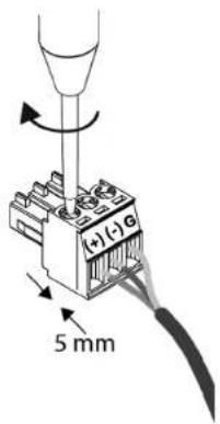
Ashly recommends a stripped wire length of 5mm (0.2 in) for use with Euroblock connectors.
Note: If using an unbalanced input, connect the signal wire to the (+)input pin, connect the shield wire to the (-) input pin, optionally use a piece of wire to link between the (-) input pin and the G pin.
Avoid running low level signal wires in close proximity or parallel to long speaker cables, AC power cables, or power transformers, as they can induce hum or oscillation.
2.3 Speaker Wire
Note: The sound system installer is responsible for using loudspeaker wiring that is in compliance with local electrical code. The following recommendations for speaker wiring are based on US National Electrical Code Article 725. These are only guidelines, consult your local code for specific up to date requirements.
- Class 2 wiring is typically used when the maximum measured open-circuit speaker output voltage is less than 120V rms.
- Class 3 wiring is typically used if the measured open circuit output voltage exceeds 120V rms, such as when amplifiers are used in bridged mode. See the specifications for specific model configurations that may require Class 3 speaker wiring.
Speaker wire gauge: MA amplifiers are capable of delivering high levels of output current, so the wire gauge used for speaker outputs is important. Inadequate wire gauge, especially over long distance, adds significant resistance to the speaker's own impedance, reducing the power which is actually delivered to the speaker. It could also result in a decreased damping factor and potential fire hazard. Since power at the speaker load is of primary concern in system design, refer to the table below to best determine appropriate wire gauge for your application.
The following table lists the resistance per 100 feet of common copper wire gauges, and also lists the percentage of the speaker load power which would be lost as heat in an arbitrary 100 ft run of different gauges of 2-conductor copper speaker wire.
| Wire Gauge | Ohms /100ft | 8Ω load | 4Ω load | 2Ω load |
| #8 0.0605Ω 0.8% | 1.5% | 3% | ||
| #10 0.1018Ω 1.3% | 2.5% | 5% | ||
| #12 0.1619Ω 2.0% | 4.0% | 8% | ||
| #14 0.2575Ω 3.2% | 6.4% | 12.8% | ||
| #16 0.4094Ω 5.1% | 10.2% | 20.4% | ||
| #18 0.6510Ω 8.1% | 16.3% | 32.6% |
This table expresses the power loss as a percentage of the load's power rather than the total amplifier output power in order to accurately determine power loss at other cable lengths. For example, if you plan to deliver 150 watts to an 8 Ohm load through 50 ft of 14 ga. cable, the power loss in the cable would be half that of a 100 ft run of #14 wire as shown in the table, or 1.6% of 150W, which is an insignificant 2.4 watts. However, if you were to run 200 ft of 18 ga. cable to a 2 Ohm load, the loss would be twice that of the 100 ft run shown in the table, or 65.2% of 250W, which is 163 watts lost as heat. Always be sure to use adequate gauge speaker wire.
2.4 Remote Control Wire
- Remote DC level control - Bell or telephone wire is sufficient for DC level control, as well as CAT5 cable. The V+ and Ground pins from one amplifier channel can be shared with other remote DC level controls wired to the same amplifier, however do not connect remote control ground to any external grounds.
- Remote Standby - This is a logic level signal, use low gauge wire, shielding is unnecessary.
MA Amplifier • Operating Manual
2.5 Mechanical
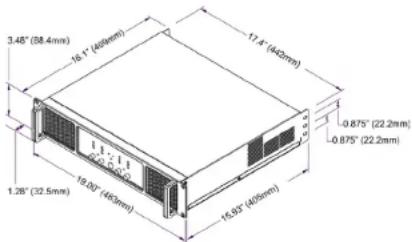
Each amplifier model is 2RU and is designed to fit into a 19-inch equipment rack with minimum depth of 16.1" (409mm). Use four screws when mounting the amplifier to the front rack rails. Rear support is recommended for mobile or touring use. In some installations where the sound system is exposed to a high level of RF noise or system-induced oscillation, it may be necessary to ground the amplifier's chassis to the rack enclosure. This is accomplished using star type lockwashers on the four rack mounting screws, placed between the amplifier chassis and the rack rails. These star washers will penetrate through the amplifier and rack rail finish to adequately ground the chassis to the rack.
2.6 Cooling
Air vents on the amplifier front, back, and side panels must have access to free flowing room temperature air. Cool air is drawn in through the front panel and blown out through the rear panel. It is not necessary to leave empty rack spaces above or below the amplifier. See specifications for amplifier thermal output characteristics in BTU/hr.
Table of Contents
3 Amplifier Protection
Power-On Delay: All models have a two second turn-on delay to prevent excessive in-rush current when first powered on.
Thermal Protection: Cooling fans are continuously variable, reaching their maximum speed when an amplifier channel reaches 80% of it's safe operating temperature. Temp LEDs turn on when signal limiting countermeasures are being applied to that channel due to over temperature conditions.
Overpower Protection: To protect internal components against overpower conditions, a protection scheme in each output stage reduces audio output power until the fault condition is no longer present.
Output DC and Rail Fault Protection: Output DC on any channel will trigger the Protect LED and mute that channel.
AC Mains: If the AC Mains line voltage exceeds or falls below the specified operating range, the amplifier will temporarily shut down. It will automatically restart as soon as the AC line voltage returns to the specified range.
For details on these and other amplifier protection schemes, plus their LED codes, refer to the troubleshooting section.
MA Amplifier • Operating Manual
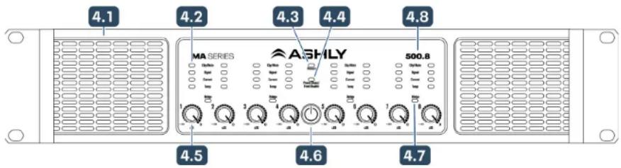
4 Front Panel Features MA500.8 shown
4.1 Air Vents
Cool air enters in through the amplifier front and is vented out the rear.
4.2 Channel LED Indicators
- CLIP/MUTE(red):
CLIPPING is indicated when the speaker output reaches 95% (-0.5dB) of maximum power.
MUTE is indicated when front panel level or DC level controls are fully attenuated.
- SIGNAL (green) is indicated when amplifier output voltage reaches 4 Volts peak.
- CURRENT (green) indicates when the current to the load is greater than 2 Amps peak.
- TEMP (yellow) indicates that automatic counter-measures are being applied due to an excessive internal temperature.
4.3 Protect LED
The red protect LED initially turns on to indicate that real-time countermeasures are being applied to overpower, over-temperature, or rail voltage fault conditions while the amp is still running.
If the countermeasures are unsuccessful and the amplifier protects itself by shutting down, the protect LED remains on and the amplifier's power must be cycled before resuming normal operation.
The exception to this is when the amp shuts down due to the AC mains voltage being out of range, in which case the amp automatically
restarts as soon as the AC mains line voltage returns to the specified operating range.
See the troubleshooting section for all Protect LED fault codes.
4.4 Front Disable/Power Share LED
- 4.4a - FRONT PANEL DISABLE - This LED lights RED when the front panel controls (power switch and channel attenuators) are disabled via the back panel DIP switch.
- 4.4b - POWER SHARE - This LED lights GREEN when power sharing is enabled via back panel DIP switch. See section 5.7d for more information on power sharing.
- This LED lights AMBER when both Front Panel Disable and Power Share are engaged.
4.5 Channel Attenuators
These control the level of the amplifier, and work in combination with the remote DC level controls. When an input attenuator is turned fully off, the red Clip/Mute LED for that channel turns on to indicate mute status. Front panel attenuators and the power switch can be disabled using the back panel DIP switch (sec. 5.7b).
4.6 Power Switch/LED
This switch is used for powering the amplifier on or off. Its white LED lights solid when the amplifier is on and flashes at 1 Hz when in standby mode. The power switch can be disabled using the back panel DIP switch. The three possible power switch LED conditions are:
- Fully lit: The amplifier is powered up, even if the power switch has been disabled, in which case the disable LED will be on.
- Flashing: The amplifier is in standby mode.
• Fully off: The amplifier is completely off.
4.7 Bridge LED
This green LED indicates when a channel pair is set to BRIDGE mode from the back panel switch (sec. 5.6). In bridge mode, only the odd numbered input and level control for that channel pair is used.
4.8 Model Number
The first three numbers of model number express the power rating per channel of the amplifier. For example, "500" mean 500W per channel, "250" means 250W per channel. The last number is the model's channel count.
Table of Contents
MA Amplifier • Operating Manual
5 Rear Panel Features
5.1 Audio Inputs
Balanced Input
Euroblock connectors
(3.5mm) are used for wiring input signals.
If using unbalanced
(single-ended) inputs, connect
the signal wire to the (+)input pin, connect the shield wire to the (-) input pin, and optionally use a piece of wire to link between the (-) input pin and the G pin.
5.2 Remote VCA Level Control Input
Every input channel has a
potentiometer circuit available for remote DC level control of that channel. The illustration to the right shows proper wiring
per channel. Shielded wire is not required, and there is no limit to wire length. Do not use any other
ground source. If multiple remote DC level controls are used for different channels, the same ground and V+ sources can be shared.
5.3 High Pass Filter DIP Switch
An 80Hz 2nd order hipass filter is independently available on every channel to reduce low frequency content going to a speaker.
5.4 Clip Limiter DIP Switch
The clip limiter prevents an amplifier channel from sending clipped audio to the speaker.
When the clip limiter is enabled, input signal level is automatically attenuated whenever the full rated output power is exceeded.

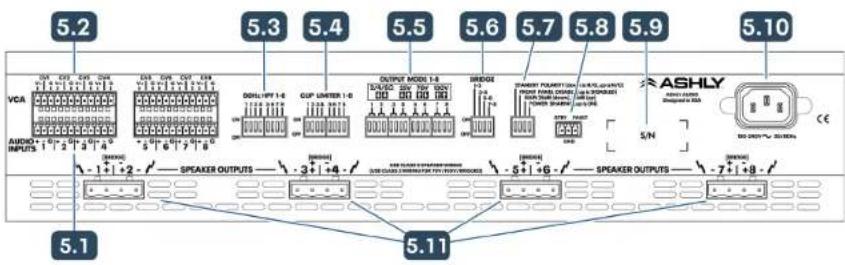
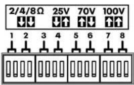
5.5 Output Mode DIP Switch
Output mode
for amplifier
channels can be
set as shown for
low impedance,
25V, 70V, or
100V output
using the pair of
DIP switches assigned to each channel.
5.6 Bridge Mode DIP Switch
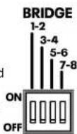
This switch places the indicated channel pair into bridge mode,
combining two amplifier outputs for more power to a single speaker
load. Bridge mode uses only the odd numbered input and level control, disabling the even numbered input and level control for that channel pair. Speaker outputs in bridge mode must be wired differently, as shown on the back of the amplifier and in section 5.11.
5.7 Utility DIP Switch Functions:
5.7a Standby Polarity
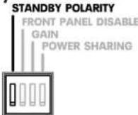
The Standby Polarity DIP switch sets the polarity requirement for placing the amplifier into standby using the STBY contact closure connector. When standby polarity switch is set to N/O (DOWN - normally open), the
amp goes into standby whenever the STBY to GND circuit is closed. When standby polarity is set to UP, or N/C (normally closed), the amp goes into standby whenever the STBY to GND circuit is open.
STBY FAULT
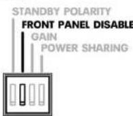
5.7b Front Panel Disable
The Front Panel Disable DIP switch de-activates all front panel level controls and power switch when in the UP position. NOTE: Disabling the front panel controls does not disable the VCA remote DC level controls.
MA Amplifier • Operating Manual
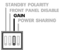
5.7c Gain
This DIP switch sets the voltage gain of all amplifier channels to either 26dB (DOWN) or 36dB (UP). This is useful when matching an amplifier to input source signal strength.
5.7d Power Sharing
MA amplifiers have a separate power supply for each group of four channels. Power sharing only occurs within each group (ch.1-4 on all models, ch.5-8 on eight channel models).
Ashly's proprietary power sharing algorithms continually sense and respond to the signal and speaker loads to use all available power from the amplifier's power sur greater efficiency and b power to all speaker load
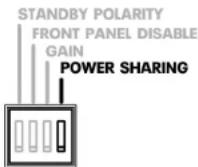
Power sharing is enabled on the amplifier when the power sharing DIP switch is in the UP position.
When power sharing is turned on, the amplifier continuously detects and "learns" input signal and speaker load characteristics within each channel group, then intelligently allocates power to each speaker output* within the group in order to optimize and maximize available power to each channel, up to the limit of the power supply, all while drawing less average current from the wall outlet.
Table of Contents
For example, when power sharing is turned off, all four channels on a MA500.4 deliver up to their rated output of 500W/ch. That power is fixed and held in reserve for each channel, whether it's needed or not.
When power sharing is turned on however, the output power on any channel can increase above its normally rated power if other channels in its group require less power. A typical application would be a biamped system with a subwoofer on one channel (or bridged pair), and full range cabinets on other channels which require less power than the subwoofer.
In MA500 Watt amplifiers with power sharing turned on, the maximum power output from any one channel is now 900W (1,800W bridged), nearly double the normal rated power. Note that the total output power available within a group of four channels still remains at 2,000W, the group power supply's maximum output. In other words, if one channel is generating 900W output power at any given moment, the other three channels only have 1,100W left to distribute amongst themselves.
In MA250 Watt amplifiers, normally fixed at 250W/ch, enabling power sharing means that the maximum power output on any one channel is now 450W, while the total available power for all four channels still remains at 1,000W.
Power sharing works the same for Low-Z, 70V, or 100V output loads, which can all be used independently within the same group of four outputs.
*25V Output: With power sharing enabled, a channel configured for 25V output can yield its unused power to other channels, however the 25V channel cannot receive additional shared power from the other channels. In other words, 25V power is always limited to the normal rated amplifier power, either 500W or 250W per channel depending on the amp model.
5.8 Fault & Standby Connections
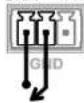
MA amplifiers provide a fault logic output pin that remains high (+5V) during normal operation. The pin goes low (G) if the amplifier is in standby mode, is powered off, or is in a protect mode fault state (the light is on). For a complete table de protect mode fault state conditions respective LED codes and fault pin see troubleshooting (section 6).
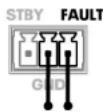
For details on Standby, see section 5.7a.
5.9 Serial Number Sticker
This sticker identifies the product model number, serial number, and AC mains current/power rating.
5.10 AC Mains Connector
Always use the AC cord provided by Ashly for connecting to mains power. The amplifier is compatible with nominal mains voltage from 100VAC to 240VAC. WARNING: Do not remove or lift the mains connector ground.
5.11 Speaker Output Connectors
7.62mm Euroblock connectors are used for convenient and secure wiring to speaker loads.
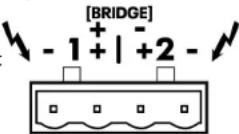
If the channel pair is set for Bridge mode, use the center two pins and observe polarity as shown. Always use sufficient speaker wiring (see section 2.3).
MA Amplifier • Operating Manual
6 Troubleshooting
No AC Power
- Is the detachable AC power cord properly installed? Is it plugged into a known live outlet?
- Has the power switch been disabled?
No Amplifier Output
• Is the amplifier in Standby Mode?
• Is there signal getting to the amplifier?
• Is the input signal properly wired?
- Are output connectors properly wired?
- Are front panel or VC remote control attenuators turned down?
• Is the Amplifier in Protect Mode? (see table)
Attenuators Don't Work
• Have the front panel controls been disabled using the rear panel DIP switch?
Still Not Working?
- Contact Ashly technical support at 1-800-705-2102, or email service@ashly.com
Protect Mode - Front Panel LED Error Codes:
| Protect Mode Fault Description | Power LED | Protect LED | Fault Pin Output | Clip/Mute LED | Signal LED | Current LED | Temp LED |
| ^ Amp Power Module Channel Protect /ch On | * | Low (0) | * | * | |||
| ^ Channel Thermal Protect /ch On | * | High (1) | * | ||||
| ^ Power Supply Thermal Protect (all 4) On | * | High (1) | * | ||||
| ^ Power Supply Out Of Range (all 4) On | * | Low (0) | * | ||||
| ^ Amp Channel DC Protect /ch On | * | Low (0) | * | * | |||
| ^ Amp Channel Over-Temperature /ch On | * | Low (0) | * | * | |||
| ^ Power Supply Over-Temperature(all 4) On | * | Low (0) | * * | * | |||
| ^ Power Supply Rails Too High (all 4) On | * | Low (0) | * | ||||
| ^ Micro-Controller Over-Temperature(all 4) | On | * | Low (0) | * * | * * | ||
| ^ Amp Channel Thermal Protect /ch | Standby | * | Low (0) | * | |||
| ^ Power Supply Thermal Protect (all 4) | Standby | * | Low (0) | * | |||
| ^ Power Supply Out Of Range (all 4) | Standby | * | Low (0) | * | |||
| ^ Amp Channel DC Protect /ch | Standby | * | Low (0) | * | * | ||
| ^ Amp Channel Over-Temperature /ch | Standby | * | Low (0) | * | * | ||
| ^ Power Supply Over-Temperature (all 4) | Standby | * | Low (0) | * * | * | ||
| ^ Power Supply Rails Too High (all 4) | Standby | * | Low (0) | * | |||
| ^ Micro-Controller Over-Temperature(all 4) | Standby | * | Low (0) | * * | * * |
'Amp still passes audio (unless amp is in Standby Mode), enacts countermeasures, automatic recovery
"Amp mutes until fault clears, automatic recovery
* Non-recoverable fault, must reset Amp by cycling AC power
Table of Contents
MA Amplifier • Operating Manual
7 Specifications
General Power Amplifier Specifications (0dBu = 0.775V rms)
Amplifier Model MA500.8 MA500.4 MA250.8 MA250.4
Maximum Output Power, (Power Sharing OFF*)
Watts per channel, all channels driven at rated load
Low Z output, per channel
| 2 Ohm 500 500 250 250 | |||
| 4 Ohm 500 500 250 250 | |||
| 8 Ohm 500 500 250 250 |
Low Z output, per bridged channel pair**
| 4 Ohm 1000* 1000* 500* 500* | |||
| 8 Ohm 1000* 1000* 500* 500* |
25V/70V/100V** output, per channel
| 25V 500 500 250 250 | |||
| 70V 500 500 250 250 | |||
| 100V | 500 500 | 250 250 |
* With Power Sharing ON: The total available power across each group of four channels is intelligently allocated based on signal and speaker load characteristics, up to a maximum of 900W/ch on MA500 models, and 450W/ch on MA250 models.
** May require Class 3 speaker wiring, all others use Class 2 wiring. See section 2.3
Total Power Draw - Watts, all channels driven, 1/8 power sinewave
| Standby | 20 | 10 | 20 | 10 |
| Idle (no signal) | 110 55 | 10 | 55 | |
| 1/8 max power 2 Ohm | 740 375 | 435 225 | ||
| 1/8 max power 4 Ohm | 680 340 | 390 195 | ||
| 1/8 max power 8 Ohm | 660 335 | 390 195 | ||
| 1/8 max power 25V | 790 380 | 425 205 | ||
| 1/8 max power 70V | 660 335 | 385 190 | ||
| 1/8 max power 100V | 650 330 | 380 190 |
Total Current Draw - in Amps, all channels driven, 1/8 power sinewave, 120VAC (divide by 2 for 240VAC)
| Standby mode | 0.4 | 0.2 0.4 | 0.2 | |
| Idle (no signal) | 1.08 | 0.55 | 1.08 | 0.55 |
| 1/8 max power 2 Ohm 6 | 3 3.2 3.7 | 1.95 | ||
| 1/8 max power 4 Ohm 5 | 8 2.9 3.35 1 | 7 | ||
| 1/8 max power 8 Ohm | 5.65 | 2.85 | 3.35 1.7 | |
| 1/8 max power 25V | 6.75 | 3.25 | 3.65 | 1.75 |
| 1/8 max power 70V | 5.65 2.8 | 3.35 | 1.65 | |
| 1/8 max power 100V 5.6 | 2.8 | 3.3 | 1.65 |
Table of
Contents
Total Thermal Dissipation - in BTU/hour with typical input, all channels driven, 120VAC
| Amplifier Model MA500.8 MA500.4 MA250.8 MA250.4 | ||||
| Standby mode | 76 | 44 | 65 | 32 |
| Idle (no signal) | 209 105 | 184 | 96 | |
| 1/8 max power 2 Ohm | 818 426 | 631 341 | ||
| 1/8 max power 4 Ohm | 614 307 | 477 239 | ||
| 1/8 max power 8 Ohm | 546 290 | 477 239 | ||
| 1/8 max power 25V | 989 443 | 597 273 | ||
| 1/8 max power 70V | 546 290 | 460 222 | ||
| 1/8 max power 100V | 512 272 | 443 222 | ||
Input Sensitivity - in Volts(rms) and dBu, per back panel Gain Switch
| @26dB gain | 3.87V(+14.0dBu) | 3.87V(+14.0dBu) | 3.16V(+12.2dBu) | 3.16V(+12.2dBu) |
| @36dB gain | 1.22V(+4dBu) | 1.22V(+4dBu) | 1.00V(+2.2dBu) | 1.00V(+2.2dBu) |
Audio Specifications
| Signal to Noise Ratio, 26dB input sensitivity, 20Hz-20kHz, unweighted | 500W Models | 250W Models |
| Low-Z Mode | >108 | >105 |
| 25V Mode | >99 | >99 |
| 70V Mode | >108 | >108 |
| 100V Mode | >112 | >112 |
| Distortion (SMPTE, typical) | <0.5% | |
| Distortion (THD+N, typical, 8 Ohm, 10dB below rated power), 20Hz-20kHz | <0.2% | |
| Frequency Response | 20Hz-20kHz, +/-0.05dB | |
| Channel Separation(dB from full output, 1kHz) | -75dB | |
| Damping Factor (8 Ohm load, <1kHz) >25D | ||
| Input Impedance | 10k Ohm | |
| Maximum Input Level | +21dBu | |
MA Amplifier • Operating Manual
Specifications (continued)
| DIP Switch settings (per channel) | |
| Input High Pass Filter 80Hz 2nd order HPF, | On (UP), Off (DOWN) |
| Clip Limiter On (UP), Off (DOW | N) |
| Output Mode (two DIP switches per ch.) | Lo-Z (2/4/8 Ohm), 25V, 70V, 100V |
| Bridge (per channel pair) | Bridge (UP), Normal (DOWN) |
| DIP Switch settings (global) | |
| Standby Polarity Normally Open (DOWN) | Normally Closed (UP) |
| Front Panel Disable Disabled (UP), Normal Gain 26dB (DOWN), 36dB (UP) | (DOWN) |
| Power Sharing On (UP), Off (DOWN) | |
| Connectors | |
| Audio Inputs Euroblock (3.5mm), (+), (-), Gnd | |
| Remote DC Volume Control VCA Inputs | Euroblock (3.5mm), (V+), (CV), Gnd |
| Standby Contact Closure Euroblock (3.5mm), Stby, Gnd | |
| Fault Logic Out (normally High, goes Low during Standby, Power Off, or Fault) | Euroblock (3.5mm), Fault, Gnd |
| Speaker Output Euroblock (7.62mm) | |
| Front Panel LED Indicators | |
| Power Switch LED (white) On, Off, Standby (flashing) | |
| Clip/Mute LED, per channel (red) On at 95% max output(0.5dB below max), Mute | |
| Signal LED, per channel (green) On when amp output > 4V Peak | |
| Current LED, per channel (green) On at >2 Amps to speaker load | |
| Temp LED, per channel (yellow) On when thermal counter-measures are being applied | |
| Bridge LED, per channel pair (green) On, Off | |
| Protect LED (red) -see troubleshooting section for Protect LED error codes | On for fault condition counter-measures or shut-down, Off |
| Front Disable / Power Share LED | On red when front panel disabled, On green if power share enabled |
| Other | |
| Attenuators | Per channel: front panel, Fully off = Mute |
| Remote Control Options | WR-1, WR-1.1 DC level control |
| Amplifier Protection | In-rush current, over-temperature, output DC, output over-power, AC mains voltage, mains fuses |
| Cooling | Continuously variable fan |
| Power Requirements | |
| Nominal Voltage Input | 100-240VAC, 50-60Hz |
| Operating Range | 70-270VAC, 50-60Hz |
| Minimum Power-up | 85VAC, 50-60Hz |
| Power Supply Type | SMPS with active PFC (Power Factor Correction) |
| AC Mains Line Cord Connector | Detachable Nema 5-15 for USA (may vary for export) |
| Environmental | 32°F-140°F, (0°C-60°C) at rated power, noncondensing |
| Unit Dimensions (all models) | 19"W x 3.5"H x 16.1"D (483 x 89 x 409mm) |
| Unit Weight by Model | MA500.8: 24.5 lbs (11.1kg) MA500.4: 18.5 lbs (8.39kg) MA250.8: 24.5 lbs (11.1kg) MA250.4: 18.5 lbs (8.39kg) |
| Shipping Dimensions (all models) | 21.9"W x 5.43"H x 19.3"D (556mm x 13.8mm x 489mm) |
| Shipping Weight by Model | MA500.8: 29lbs (13.2kg) MA500.4: 23lbs (10.5kg) MA250.8: 29lbs (13.2kg) MA250.4: 23lbs (10.5kg) |
| Safety/Compliance | cTUVus, CE, FCC, RoHS |
MA Amplifier • Operating Manual
LIMITED WARRANTY (USA ONLY)
(Other countries please contact your respective distributor or dealer.)
For units purchased in the USA, warranty service for this unit shall be provided by ASHLY AUDIO in accordance with the following warranty statement.
ASHLY AUDIO, an exertis | JAM business, warrants to the owner of this product that it will be free from defects in workmanship and materials for a period of FIVE years from the original-date-of-purchase, with the exception of touch-screen displays and motorized faders which are warranted for THREE years from the original-date-of-purchase.
ASHLY AUDIO will without charge, repair or replace at its discretion, any defective product or component parts upon prepaid delivery of the product to the ASHLY AUDIO factory service department, accompanied with a proof of original-date-of-purchase in the form of a valid sales receipt. This warranty gives you specific legal rights, and you may also have other rights, which vary from state to state.
EXCLUSIONS: This warranty does not apply in the event of misuse, neglect, or as a result of unauthorized alterations or repairs made to the product. This warranty is void if the serial number is altered, defaced, or removed. ASHLY AUDIO reserves the right to make changes in design, or make additions to, or improvements upon, this product without any obligation to install the same on products previously manufactured.
Any implied warranties, which may arise under the operation of state law, shall be effective only for FIVE years (THREE years for touch-screen displays and motorized faders) from the original-date-of-purchase of the product. ASHLY AUDIO shall be obligated to only correct defects in the product itself. ASHLY AUDIO is not liable for any damage or injury, which may result from, or be incidental to, or a consequence of, such defects. Some states do not allow limitations on how long an implied warranty lasts, or the exclusion, or limitation of incidental or consequential damages, so the above limitations or exclusions may not apply to you.
OBTAINING WARRANTY SERVICE:
For warranty service in the United States, please follow this procedure:
1) Contact the Ashly Service Department at 800-705-2102 or https://ashly.com/technical-support/to receive an RMA number. You must receive a RMA from the Service Department before sending your unit to Ashly.
2) Return the product to ASHLY AUDIO freight prepaid, with a written statement describing the defect and application that the product is used in. ASHLY AUDIO will examine the product and perform any necessary service, including replacement of defective parts, at no further cost to you.
3) Ship your product to:
ASHLY AUDIO
Service - RMA (insert RMA#)
847 Holt Road
Webster, NY 14580-9103
ASHLY AUDIO 847 Holt Road Webster, NY 14580-9103, USA
Phone (800) 705-2102 Fax: (585) 872-0739
www.ashly.com
An exertis | JAM business
©2023 Ashly Audio. All rights reserved worldwide.
All features, specifications, and graphical representations are subject to change or improvement without notice.
Table of Contents
MA2111824
ASHLY®
- Unpacking
- About Ashly
- MA Amplifier • Operating Manual
- Table of Contents
- Introduction
- Features
- Requirements
- AC Mains
- Input Signal Wire
- Speaker Wire
- Remote Control Wire
- Mechanical
- Cooling
- Amplifier Protection
- Front Panel Features MA500.8 shown
- Air Vents
- Channel LED Indicators
- Protect LED
- Front Disable/Power Share LED
- Channel Attenuators
- Power Switch/LED
- Bridge LED
- Model Number
- Rear Panel Features
- Audio Inputs
- Remote VCA Level Control Input
- High Pass Filter DIP Switch
- Clip Limiter DIP Switch
- Output Mode DIP Switch
- Bridge Mode DIP Switch
- Utility DIP Switch Functions:
- 5.7a Standby Polarity
- 5.7b Front Panel Disable
- 5.7c Gain
- 5.7d Power Sharing
- Fault & Standby Connections
- Serial Number Sticker
- AC Mains Connector
- Speaker Output Connectors
- Troubleshooting
- No AC Power
- No Amplifier Output
- Attenuators Don't Work
- Still Not Working?
- Specifications
- LIMITED WARRANTY (USA ONLY)
- OBTAINING WARRANTY SERVICE:
Brand : Ashly
Model : MA 250.4
Category : Blender