
DHY-04T - Professional audio equipment Sonifex - Free user manual and instructions
Find the device manual for free DHY-04T Sonifex in PDF.


| Product Type | Twin Rackmount Automatic Digital Telephone Hybrid (TBU) |
| Model | DHY-04T |
| Manufacturer | Sonifex Ltd |
| Dimensions (Height x Width x Depth) | 4.5 cm (1U) x 48.3 cm (19" rack width) x 17.5 cm |
| Net Weight | 2.80 kg |
| Gross Weight (Boxed) | 4.4 kg |
| Power Supply | Universal 90-250 V AC, 47-63 Hz, max 10W |
| Mains Connection | IEC CEE22 inlet, auto-ranging |
| Audio Input (Analogue) | XLR-3-31 female, balanced, 10 kΩ (line) or 2 kΩ (mic via switch) |
| Audio Input (Digital) | XLR-3-31 female, AES/EBU, 110 Ω, sample rates up to 96 kHz |
| Audio Output (Analogue) | XLR-3-32 male, balanced, 50 Ω, 0 dBu nominal |
| Audio Output (Digital) | XLR-3-32 male, AES/EBU, 110 Ω, follows input |
| Telephone Line Interface | RJ11 6/4 socket, 600/900 Ω + complex impedances |
| Handset Connection | RJ11 6/4 socket |
| Remote Control Port | 9-pin D-type female (RS232 & GPI/O) |
| Ethernet Port | RJ45, 10/100/1000 Mbps auto-negotiation, built-in web server |
| Conference Port | RJ45, for linking two DHY-04 units or record output |
| Line Balance Rejection | 70 dB typical (80-88 dB on complex waveforms) |
| Echo Cancellation | Adaptive up to 250 ms, default 24 ms |
| Frequency Response (Line) | 250 Hz - 4 kHz (-3 dB ref 1 kHz) |
| Front Panel Controls | 4 Speed Dial buttons, Redial, Line Hold/Connect, gain switches, LED bargraphs |
| Indicators | Power LED, AES Lock LED (red/green), Line Hold LED (flash/steady) |
| Configuration | Rear DIP switches + web browser GUI |
| Country Code Selection | Supported via DIP switches or web (many countries, see manual) |
| Approvals | CE, UKCA, ACMA, BABT, ETSI, REN=1 |
| Operating Temperature | 0°C to 50°C |
| Cleaning & Maintenance | Wipe with a dry cloth; no user-serviceable parts inside |
| Safety | Class I construction; must be earthed; disconnect mains before opening |
| Spare Parts & Repair | Contact Sonifex or supplier; no user-serviceable parts |
Frequently Asked Questions - DHY-04T Sonifex
User questions about DHY-04T Sonifex
0 question about this device. Answer the ones you know or ask your own.
Ask a new question about this device
Download the instructions for your Professional audio equipment in PDF format for free! Find your manual DHY-04T - Sonifex and take your electronic device back in hand. On this page are published all the documents necessary for the use of your device. DHY-04T by Sonifex.
USER MANUAL DHY-04T Sonifex
Single Freestanding Automatic Digital TBU, AES/EBU & Analogue I/O With Ethernet
DHY-04S
Single Rackmount Automatic Digital TBU, AES/EBU & Analogue I/O With Ethernet
DHY-04T
Twin Rackmount Automatic Digital TBU, AES/EBU & Analogue I/O With Ethernet
Manufacturers of audio & video products for radio & TV broadcasters
SONIFEX
DHY-04 Handbook
For the latest Sonifex handbook information please visit the Sonifex website at www.sonifex.co.uk
This handbook is for use with the following product:
DHY-04 Single Freestanding Automatic Digital TBU, AES/EBU & Analogue I/O With Ethernet
DHY-04S Single Rackmount Automatic Digital TBU, AES/EBU & Analogue I/O With Ethernet
DHY-04T Twin Rackmount Automatic Digital TBU, AES/EBU & Analogue I/O With Ethernet
©Sonifex Ltd, 2022
All Rights Reserved
Revision 1.09, September 2022
Stock Code: 30-281
AW10663
Sonifex Ltd, 61, Station Road, Irthlingborough,
Northants, NN9 5QE, England.
Tel: +44 (0)1933 650 700
Fax: +44 (0)1933 650 726
Email: sales@sonifex.co.uk
Website: https://www.sonifex.co.uk
Information in this document is subject to change without notice and does not represent a
commitment on the part of the vendor. Sonifex Ltd shall not be liable for any loss or damage
whatsoever arising from the use of information or any error contained in this manual.
No part of this manual may be reproduced or transmitted in any form or by any means, electronic
or mechanical, including photocopying, recording, information storage and retrieval systems, for any
purpose other than the purchaser's personal use, without the express written permission of Sonifex
Ltd. Unless otherwise noted, all names of companies, products and persons contained herein are part
of a completely fictitious adaptation and are designed solely to document the use of Sonifex product.
SONIFEX
MADE IN BRITAIN
Contents
Contents
Product Warranty - 2 Year Extended i
Sonifex Warranty & Liability Terms & Conditions i
- Definitions i
- Warranty
Unpacking Your Product ii
Repairs & Returns iii
Conformity
CE Conformity iii
ACMA Conformity iii
Safety & Installation of Mains Operated Equipment iii
Voltage Setting Checks iii
Power Cable & Connection iii
WEEE Directive iv
Atmosphere/Environment
1 What Is A Telephone Hybrid?
The Best Telephone Hybrid in the World Just
Got Better!
DHY-04 Single Freestanding Automatic Digital TBU 2
Available Formats 3
DHY-04S Single Rackmount Automatic Digital TBU 3
DHY-04T Twin Rackmount Automatic Digital TBU 3
Front Panel Controls
Power LED Indicator 4
Reset Button 4
Speed Dial Buttons 4
AES/EBU Lock LED 4
Line Hold/Connect Button 4
Gain Switches (Level To & From The Line) 5
LED Bargraphs 5
Status & Operating Mode Information 5
DHY-04 Internal Controls & Adjustments
Jumper and Select Switcher Functions 5
Rear Panel Controls & Connections
AES/EBU & Analogue Combined Line Output 6
Mic/Line & AES/EBU Input 6
Mic/Line Input Select Switch 6
Adjusting the Microphone Gain Level 6
Remotes 6
Conference Audio/Record Output 6
Telephone Handset 7
Telephone Line 7
RJ11 Telephone Connections 7
RS232 Serial Port 7
Ethernet Port 8
Mains Input 8
Protective Earth Terminal 8
Configuration Settings DIPSwitches 8
Country Code Selection 9
IEC Mains 13
Telephone Line 13
Handset 13
Remote Line Hold 13
Mic/Line Input 13
XLR Output 13
Using The AES/EBU Input & Output 14
Using the DHY-04 14
Call Established 15
Using the Conference Port as a Record Output 16
Using the Conference Port to Share a Stereo Digital
Audio Connection Between Two DHY-04 Units 16
4 Hybrid Technical Description 17
Electrical Interface 17
Impedance Matching 17
Echo Cancellation 17
5 Serial Port Control 19
Serial Interface Commands & Responses 19
Error Messages 19
6 Webserver & Network Discovery 20
Connecting to the Device 20
First Time Usage 20
MDNS-SD and Bonjour 20
Sonifex Service Discovery App 20
Home Page 22
Status 22
Line 22
Dial 22
Contents
Dialler Page 23
Call State 23
Dial 23
Configuration - Telephone 24
Country Code 24
Disconnect Settings 24
Answer Control 24
Auto Redial 25
Buttons 25
Configuration - Telephone Details 25
Configuration - Remote 26
Input Port 26
Output Port 27
Configuration - Misc 28
Config Name 28
Description 28
Echo Duration 28
Conference Port Function 28
Force Analogue Output 29
Save Cancellation Coeffs 29
Password Setting 30
Network Settings 31
Bonjour Name 31
Static IP Address 31
Static Subnet Mask 32
Gateway IP Address 32
Dynamic Addressing 32
Device Info Page 33
Update Firmware Page 34
Update Firmware 34
Update Config Files 35
Clear Settings 35
Log In 36
Bootstrap Mode 37
7 Technical Specification 38
Approvals Information 40
Manufacturer 40
Equipment Type 40
Approval File Reference 40
Functions 40
Specified Systems 41
Ringer Equivalence Number 41
Accessory Ports 41
Conditions 41
Series Connection 41
Facilities 41
Statutory Mark 41
Appendix 1 - Telephone Registers 42
AC Impedance Setting 43
Figures
Figure 1-1: DHY-04 Front & Rear. 2
Figure 1-2: DHY-04S Front & Rear. 3
Figure 1-3: DHY-04T Front & Rear. 3
Figure 2-1: Front Panel Controls. 4
Figure 2-2: Internal Position of Jumper J1. 5
Figure 2-3: Rear Panel Controls. 7
Figure 2-4: Configuration Settings Switches. 8
Table 2-1: Supported Disconnect Tone Details by Country. 12
Figure 3-1: DHY-04 User Connections. 13
Figure 3-2: Conference Port Cable Connections. 16
Figure 6-1: Bonjour Service Discovery Page. 21
Figure 6-2: Legacy Service Discovery Page. 21
Figure 6-3: Home Page – for basic call control and setting preset calls. 22
Figure 6-4: Dialer Page – simple screen for making calls – accessed via Home Menu drop-down. 23
Figure 6-5: Telephone Configuration – selection of telephone interface via Country Code selection. 24
Figure 6-6: Detailed Telephone Configuration and Auto redial warning message selection of telephone interface via Country Code selection with detailed information about the actual parameters being set. This screen is also used to change individual parameters for User settings. 25
Figure 6-7: Remote Port Configuration – settings of remote port and DTMF detection – accessed via Config Menu drop-down.
Figure 6-8: Misc Configuration – extra settings for DHY-04 – accessed via Config Menu drop-down. 28
Figure 6-9: Password Setting Page. 30
Figure 6-10: Network Page – settings for network interface. 31
Figure 6-11: Device Info Page – shows info about the DHY-04 device. 33
Figure 6-12: Updates Page – to update the system firmware and load/save configuration files. 34
Figure 6-13: Log In Page. 36
Figure 6-14: Bootstrap Page. 37
Table 8-1: Telephone Interface Register 16. (Use sum of required values) 42
Table 8-2: Telephone Interface Register 17. (Use sum of required values) 42
Table 8-3: Telephone Interface Register 18. (Use sum of required values) 42
Table 8-4: Telephone Interface Register 22. (Use sum of required values) 42
Table 8-5: Telephone Interface Register 23. (Use sum of required values). 42
Table 8-6: Telephone Interface Register 23 - RTO Values. 42
Table 8-7: Telephone Interface Register 23 – RCC Values. 42
Table 8-8: Telephone Interface Register 24. (Use sum of required values) 43
Table 8-9: Telephone Interface Register 26. (Use sum of required values) 43
Table 8-10: Telephone Interface Register 30. (Use sum of required values) 43
Table 8-11: Telephone Interface Register 30 - AC Impedance settings. 43
Table 8-12: Telephone Interface Register 31. (Use sum of required values) 44
Table 8-13: Telephone Interface Register 59. (Use sum of required values) 44
Warranty Registration
SONIFEX
Register Online for an Extended 2 Year Warranty
As standard, Sonifex products are supplied with a 1 year back to base warranty.
If you register the product online, you can increase your product warranty to 2 years and we can also keep you informed of any product design improvements or modifications.
Product: ____ Serial No: ____
To register your product, please go online to www.sonifex.co.uk/register
SONIFEX
Sonifex Limited • 61 Station Road • Irthlingborough • Northamptonshire • NN9 5QE • United Kingdom
Tel: +44 (0)1933 650 700 • Fax: +44 (0)1933 650 726 • Email: technical.support@sonifex.co.uk • Internet: www.sonifex.co.uk
Product Warranty - 2 Year Extended
As standard, Sonifex products are supplied with a 1 year back to base warranty. In order to register the date of purchase and so that we can keep you informed of any product design improvements or modifications, it is important to complete the warranty registration online. Additionally, if you register the product on the Sonifex website, you can increase your product warranty to 2 years. Go to the Sonifex website at: www.sonifex.co.uk/register to apply for your 2 year warranty.
Note: For your own records the product serial number is recorded on the CE certification page of this handbook.
Sonifex Warranty & Liability Terms & Conditions
1. Definitions
'the Company' means Sonifex Ltd and where relevant includes companies within the same group of companies as Sonifex Limited.
'the Goods' means the goods or any part thereof supplied by the Company and where relevant includes: work carried out by the Company on items supplied by the Purchaser; services supplied by the Company; and software supplied by the Company.
'the Purchaser' means the person or organisation who buys or has agreed to buy the Goods.
'the Price' means the Price of the Goods and any other charges incurred by the Company in the supply of the Goods.
'the Warranty Term' is the length of the product warranty which is usually 12 months from the date of despatch; except when the product has been registered at the Sonifex website when the Warranty Term is 24 months from the date of despatch.
'the Contract' means the quotation, these Conditions of Sale and any other document incorporated in a contract between the Company and the Purchaser.
This is the entire Contract between the parties relating to the subject matter hereof and may not be changed or terminated except in writing in accordance with the provisions of this Contract. A reference to the consent, acknowledgement, authority or agreement of the Company means in writing and only by a director of the Company.
2. Warranty
a. The Company agrees to repair or (at its discretion) replace Goods which are found to be defective (fair wear and tear excepted) and which are returned to the Company within the Warranty Term provided that each of the following are satisfied:
i. notification of any defect is given to the Company immediately upon its becoming apparent to the Purchaser; ii. the Goods have only been operated under normal operating conditions and have only been subject to normal use (and in particular the Goods must have been correctly connected and must not have been subject to high voltage or to ionising radiation and must not have been used contrary to the Company's technical recommendations); iii. the Goods are returned to the Company's premises at the Purchaser's expense; iv. any Goods or parts of Goods replaced shall become the property of the Company; v. no work whatsoever (other than normal and proper maintenance) has been carried out to the Goods or any part of the Goods without the Company's prior written consent;
Warranty
vi. the defect has not arisen from a design made, furnished or specified by the Purchaser; vii. the Goods have been assembled or incorporated into other goods only in accordance with any instructions issued by the Company; viii. the defect has not arisen from a design modified by the Purchaser; ix. the defect has not arisen from an item manufactured by a person other than the Company. In respect of any item manufactured by a person other than the Company, the Purchaser shall only be entitled to the benefit of any warranty or guarantee provided by such manufacturer to the Company.
b. In respect of computer software supplied by the Company the Company does not warrant that the use of the software will be uninterrupted or error free.
c. The Company accepts liability:
(i) for death or personal injury to the extent that it results from the negligence of the Company, its employees (whilst in the course of their employment) or its agents (in the course of the agency); (ii) for any breach by the Company of any statutory undertaking as to title, quiet possession and freedom from encumbrance.
d. Subject to conditions (a) and (c) from the time of despatch of the Goods from the Company's premises the Purchaser shall be responsible for any defect in the Goods or loss, damage, nuisance or interference whatsoever consequential economic or otherwise or wastage of material resulting from or caused by or to the Goods. In particular the Company shall not be liable for any loss of profits or other economic losses. The Company accordingly excludes all liability for the same.
e. At the request and expense of the Purchaser, the Company will test the Goods to ascertain performance levels and provide a report of the results of that test. The report will be accurate at the time of the test, to the best of the belief and knowledge of the Company, and the Company accepts no liability in respect of its accuracy beyond that set out in Condition (a). f. Subject to Condition (e), no representation, condition, warranty or other term, express or implied (by statute or otherwise) is given by the Company that the Goods are of any particular quality or standard or will enable the Purchaser to attain any particular performance or result, or will be suitable for any particular purpose or use under specific conditions or will provide any particular capacity, notwithstanding that the requirement for such performance, result or capacity or that such particular purpose or conditions may have been known (or ought to have been known) to the Company, its employees or agents. g. (i) To the extent that the Company is held legally liable to the Purchaser for any single breach of contract, tort, representation or other act or default, the Company's liability for the same shall not exceed the price of the Goods. (ii) The restriction of liability in Condition (g)(i) shall not apply to any liability accepted by the Seller in Condition (c). h. Where the Goods are sold under a consumer transaction (as defined by the Consumer Transactions (Restrictions on Statements) Order 1976) the statutory rights of the Purchaser are not affected by these Conditions of Sale.
Unpacking Your Product
Each product is shipped in protective packaging and should be inspected for damage before use. If there is any transit damage, take pictures of the product packaging and notify the carrier immediately with all the relevant
details of the shipment. Packing materials should be kept for inspection and also for if the product needs to be returned.
The product is shipped with the following equipment, so please check to ensure that you have all of the items below. If anything is missing, please contact the supplier of your equipment immediately.
Item
Quantity
Product unit 1
IEC mains lead fitted with moulded mains plug 1
Handbook and warranty card 1
If you require a different power lead, please let us know when ordering the product.
Repairs & Returns
Please contact Sonifex or your supplier if you have any problems with your Sonifex product. Email technical.support@sonifex.co.uk for the repair/upgrade/returns procedure, or for support & questions regarding the product operation.
Conformity
The technical justification file for this product is available at Sonifex Ltd.
The declarations of conformity can be found at: https://www.sonifex.co.uk/declarations

Conformity
The products in this manual comply with the essential requirements of the relevant European health, safety and environmental protection legislation.

ACMA Conformity
The products in this manual also comply with the ACMA requirements for use in Australia and New Zealand.
Safety & Installation of Mains Operated Equipment
There are no user serviceable parts inside the equipment. If you should ever need to look inside the unit, always disconnect the mains supply before removing the equipment covers. The cover is connected to earth by means of the fixing screws. It is essential to maintain this earth/ground connection to ensure a safe operating environment and provide electromagnetic shielding.
Voltage Setting Checks
Ensure that the machine operating voltage is correct for your mains power supply by checking the box in which your product was supplied. The voltage is shown on the box label. The available voltage settings are 115V, or 230V. Please note that all products are either switchable between 115V and 230V, or have a universal power supply.
Power Cable & Connection
An IEC power connector is supplied with the product which has a moulded plug attached.
The mains plug or IEC power connector is used as the disconnect device. The mains plug and IEC power connector shall remain readily operable to disconnect the apparatus in case of a fault or emergency.
The mains lead is automatically configured for the country that the product is being sent to, from one of:
CE Certification
Territory Voltage IEC Lead Type Image
| UK & Middle East 230V UK 3 pin to IEC lead | ||
| Europe 230V | European Schuko round 2 pin to IEC lead | |
| USA, Canada and South America | 115V 3 flat pin to IEC lead | |
| Australia & New Zealand | 230V Australasian 3 flat pin to IEC lead | |
Connect the equipment in accordance with the connection details and before applying power to the unit, check that the machine has the correct operating voltage for your mains power supply.
This apparatus is of a class I construction. It must be connected to a mains socket outlet with a protective earthing connection.
Important note: If there is an earth/ground terminal on the rear panel of the product then it must be connected to Earth.
CE and UKCA
The products in this manual comply with the essential requirements of the relevant UK and European health, safety and environmental protection legislation. The technical justification file for this product is held at Sonifex Ltd. Relevant declarations of conformity can be found at:
https://www.sonifex.co.uk/declarations
WEEE Directive

Directive 2012/19/EU of the European Parliament and of the Council of 4th July 2012 lays down measures to protect the environment and human health by preventing or reducing the adverse impacts of the generation and management of waste from electrical and electronic equipment (WEEE).
The policy of Sonifex Ltd is to comply with all applicable laws of all jurisdictions having authority over Sonifex's business, including the WEEE directive. Accordingly, Sonifex has implemented a rigorous program designed to ensure compliance of its products with the WEEE directive. The latest statements can be found at:
https://www.sonifex.co.uk/company/recycling
Atmosphere/Environment
This apparatus should be installed in an area that is not subject to excessive temperature variation (<0°C, >50°C), moisture, dust or vibration.
This apparatus shall not be exposed to dripping or splashing, and no objects filled with water, such as vases shall be placed on the apparatus.
1 What Is A Telephone Hybrid?
Telephone hybrids, or telephone balance units (TBUs) provide the interface between professional audio equipment and the public telephone network. They provide protection for your equipment and the public telephone lines, allowing for varying line signals and line conditions. Automatically cancelling out the unwanted signal they also facilitate two-way communication down a single telephone line.
Each telephone hybrid has a telephone line connection, a handset connection and separate terminals for audio input and output from a broadcast mixer, or other professional audio source.
A large proportion of Sonifex hybrids are used in radio and television broadcasting applications for allowing external callers to be connected to the studio mixing console. Most of the other units are supplied to communication operations for allowing extremely effective conversion between 4-wire audio circuits and standard telephone lines.
The Best Telephone Hybrid in the World Just Got Better!
The DHY-04 telephone hybrid is an enhanced redesign of the DHY-03, the best performing telephone hybrid in the world. It now has auto-sensing combined analogue and AES/EBU inputs and outputs, front panel Speed Dial buttons, together with an Ethernet interface to allow web browser access to the configuration and internal settings. All whilst still retaining stunning line balance rejection figures. For the best sounding audio calls you're likely to hear, you should specify the DHY-04.
Key new features of the unit include:
• Auto-sensing combined analogue or AES/EBU XLR input. - AES/EBU sample rates up to 24 bit/96kHz accepted. - Configurable analogue or AES/EBU XLR output. - Ethernet port for remote configuration via web browser GUI.
- Remote dialling and line hold control via Ethernet.
- DTMF dial tone recognition for reporter remote access - a journalist can dial into the unit which can recognise a pre-programmed DTMF numeric code to automatically connect the journalist on-air.
- Four front panel speed-dial buttons for dialling 7 internally phone Speed Dial numbers.
- Front panel Redial button for redialling the last number.
Product Function:
Provides separation between send and receive signals on an analogue telephone network, provides professional level balanced input & output signals and has echo cancellation.
Typical Applications:
Radio & TV station talk shows, telephony interface to the mixer.
Features:
- Fully automatic - adapts to varying line conditions and has automatic signal limiting.
- Fully adaptive echo cancellation to 250msec - default is 24msec.
- 70dB typical line balance rejection offering superb performance and crystal clear audio.
- Front panel input and output gain controls.
- Front panel LED metering of receive and send signals.
- Built-in conferencing for 2 hybrids, so that a single telco channel on a mixing desk can receive 2 calls.
- Integrated ring detector - automatic call answering after a predetermined number of rings.
- Automatic call disconnection. Fitted with K-break, line polarity reversal and dial tone disconnect detection, defined by the country selection.
- Automatic ducking facility allows the talent to 'shout-down', or talk over, a caller by reducing the gain of the caller's signal if it goes above a certain level.
1 What Is A Telephone Hybrid?
- Local and remote line hold switching - calls can be remotely switched through a mixing console.
- Line hold/release button to control line hold circuit, illuminates to indicate the status of the line and flashes to show ring status.
- DTMF tone recognition allowing a opto-isolated GPI output to be made on receipt of selected DTMF tones, e.g. for starting a studio automation recorder automatically to record a remote telephone interview.
- International operation with built-in configurable settings for each country.
- Country selection allows the unit to provide line impedance and a simulation circuit to match the country.
- RS232 serial port for remote control of the TBU & DTMF tone dialling.
- Remote port distributes the remote line connect switch and tally output, a momentary/latch selector and the DTMF detect output.
- The remote line connect switch can be either momentary or latching in its action.
- Balanced mic/line input - 10k balanced input selectable for OdBu clean feed line, or microphone level with adjustable gain.
DHY-04 Single Freestanding Automatic Digital TBU
Figure 1-1: DHY-04 Front & Rear.
What Is A Telephone Hybrid?
- Balanced output - 0dBu low impedance balanced output, with output gain settings.
- Record output - the conferencing output can be set to give an output to record just the caller or a mix of the caller and mic/line input signals for recording both sides of the telephone conversation.
- Line limiter, bandpass filter and output noise gate with preset threshold providing low distortion audio.
- Built in universal power supply between 90V AC and 250V AC, 47-63Hz, IEC mains input. • ETSI approval compliant with European PTT specifications.
Available Formats
The DHY-04 digital telephone hybrids are available in three different
DHY-04 Single automatic digital telephone hybrid, free standing
DHY-04S Single automatic digital telephone hybrid, rackmount
DHY-04T Twin automatic digital telephone hybrid, rackmount
DHY-04S Single Rackmount Automatic Digital TBU
Figure 1-2: DHY-04S Front & Rear.
DHY-04T Twin Rackmount Automatic Digital TBU
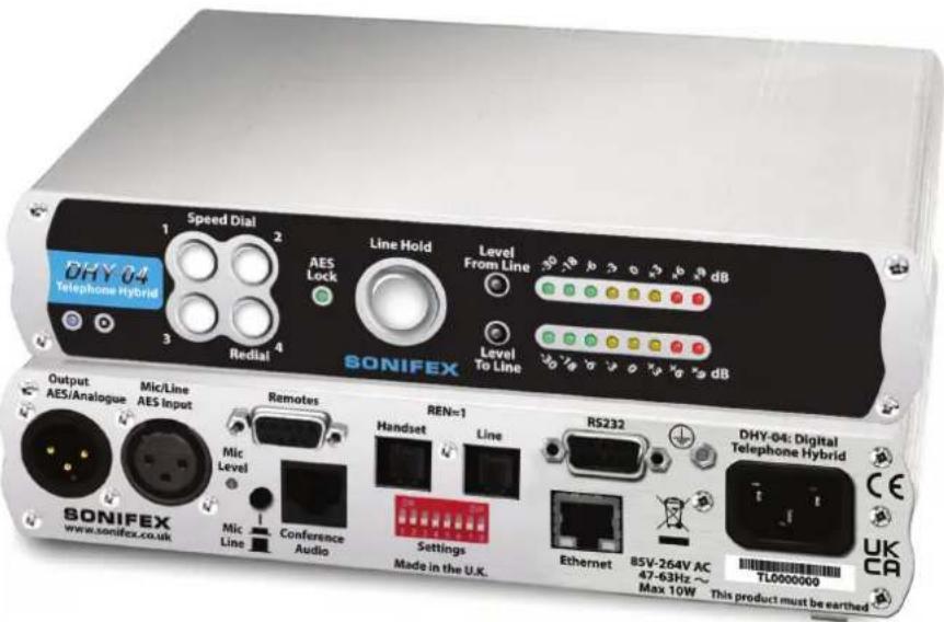
Figure 1-3: DHY-04T Front & Rear.
Front Panel Controls
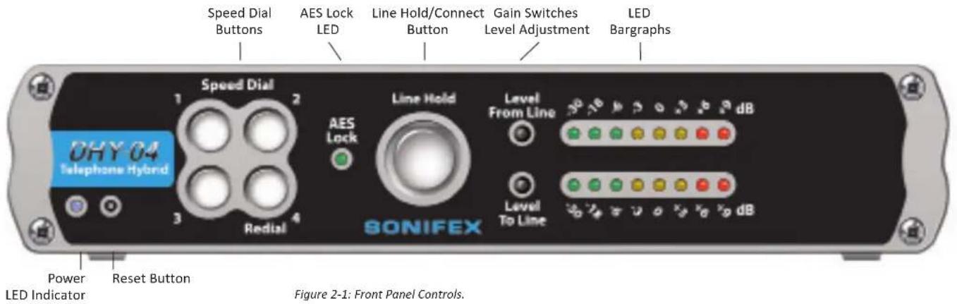
Power LED Indicator
The power LED indicates that the equipment is powered and operational when illuminated.
Reset Button
In the unlikely event that the DHY-04 unit fails to respond, press the reset button to reboot the unit.
In extremis (especially valuable when the network settings have been incorrectly entered) the unit can clear the settings to factory default by pressing the reset three times in succession as follows – press reset; wait for 7 seconds; press reset again; wait for 7 seconds; press reset again and the unit will clear all the current settings and return to the factory defaults.
Speed Dial Buttons
Press the appropriate button to call Speed Dial settings 1-4. Press and hold buttons 1-3 to call Speed Dial numbers 5-7 or press and hold Speed Dial 4 to redial the last number. The numbers are configured using the embedded webserver.
AES/EBU Lock LED
This is a red/green LED with green indicating a successful lock to the incoming AES/EBU signal, i.e. a valid AES signal is present. The LED is red for a non-valid AES/EBU input.
Line Hold/Connect Button
This is the front panel button used to connect calls to, and disconnect calls from, the telephone line. The line connect button flashes when an incoming call is detected and illuminates to indicate the call has been connected. Operation of this button can be remotely controlled by GPI.
Gain Switches (Level To & From The Line)
These switches allow gain/attenuation to be applied to the incoming & outgoing analogue audio. Each switch has 3 positions. Rotating the switches clockwise give gains of -6dB, 0dB & +6dB. The normal position for the transmit gain to the telephone line (lower switch) is 0db and for the receive gain from telephone line (upper switch) is -6dB.
LED Bargraphs
These 8 position bargraphs, by default, indicate the signal levels of the incoming XLR audio signal from the mixer (lower) and outgoing XLR audio to the mixer (upper). For best operation set the signal gain switches to achieve all 3 yellow LEDs mostly illuminated with occasional audio peaks lighting the first red LED.
The scale indicates from left to right: Green (-30dB, -18dB, -6dB); Yellow (-3dB, 0dB, +3dB); & Red (+6dB, +9dB).
Status & Operating Mode Information
The LED display is also used to indicate special operating modes and other settings as follows:
- Alternating 2 LEDs on, 2 LEDs off pattern indicates that the DHY-04 is checking the status of the Line Connect Button to test the Bootstrap Mode (see page 36)
- Alternating 4 LEDs on, 4 LEDs off pattern indicates that the DHY-04 has entered Bootstrap mode, because either the Line Hold/Connect Button was held down for approximately 10 seconds at power up, or the main code has been corrupted (most likely due to a previous incomplete firmware update).
- Alternating 8 LEDs on, 8 LEDs off pattern indicates that the DHY-04 has received an update command from the web page and is updating the firmware (valid in either Bootstrap or Normal operation).
- On normal power up, the top row of LEDs shows the current country selection (see table 2-1) with LEDs numbered from left to right reflecting the DIPSwitch settings.
DHY-04 Internal Controls & Adjustments
If you need to get inside the unit to make configuration adjustments, simply remove the 4 screws in the corners of the rear panel. The rear panel and main PCB will slide backwards out of the metal chassis.
When re-inserting the main PCB, ensure that the PCB edges are in the runners inside the chassis and also that the power LED and line connect button are in the correct place in the front panel.
Warning: The power must be switched off at the supply or the power lead must be disconnected before attempting to open the unit. Removal of the cover can expose dangerous voltages.
Warning: The telephone line plug should be disconnected from the telecommunications network exchange line before removing the cover.
Jumper and Select Switcher Functions
Put a 2 pin jumper over J1 to switch in an extra 10dB of audio input gain to allow for use of domestic level mixing desks.

Figure 2-2: Internal Position of Jumper J1.
Rear Panel Controls & Connections
AES/EBU & Analogue Combined Line Output
The line output is an XLR 3 pin male connector with the following connections (XLR-3-32, 50Ω balanced floating). It outputs either balanced analogue or AES/EBU audio by following the input, i.e. a digital input produces a digital output.
Pin 1: Screen
Pin 2: Phase
Pin 3: Non-Phase

Mic/Line & AES/EBU Input
The line input is an XLR 3 pin female connector (XLR-3-31, 10kΩ balanced floating). It is autosensing for either analogue balanced or AES/EBU (left channel) signals. Pin2
Pin 1: Screen
Pin 2: Phase
Pin 3: Non-Phase

Mic/Line Input Select Switch
This push-button switch sets the input signal mode:
Switch depressed (in) - Mic input mode selected
Switch not depressed (out) - Line input mode selected
Adjusting the Microphone Gain Level
The Mic Level preset potentiometer controls the level of the input signal when the Mic/Line Input Select Switch is set to Mic input. The input signal level in Line mode is factory set and is not affected by this control. The Mic Input will accept 200Ω microphone level signals and is balanced/floating with a maximum gain of 70dB. Use a jeweller's screwdriver to adjust the gain between 70dB and 52dB. The gain range can be extended by ±6dB by using the front panel 'Level to The Line' switch.
Remotes
The remote port allows you to control the line hold circuit from a mixing desk or other remote device and also outputs opto-isolated outputs to indicate the line hold status and the DTMF detect function.
The remote connector is a 9-way female (socket) 'D' type. To remotely control the line connect, connect pin 1 to pin 2. The action of this remote can act as momentary or latching by pin 6 having no connection or connecting to 0V respectively.
Pins 3 and 7 are an opto-isolated remote line connect indicator, and pins 5 and 7 are an opto-isolated DTMF detect output. They can use the local supply pins 4 and 8 to drive an LED indicator or a low current load.
Pin 1: Remote Line Connect Switch
Pin 2: Common - 0V
Pin 3: Opto-Isolated Line Connect Indicator - NPN Emitter
Pin 4: Common - 0V
Pin 5: Opto-Isolated User GPO (DTMF Detect*) Indicator - NPN Emitter
Pin 6: User GPI (Momentary/Latch Line Connect Switch - connect to OV for latching action*)
Pin 7: Opto-Isolated Line Connect Indicator - NPN Collector
Pin 8: 5V out (current limited supply for pins 7 & 9)
Pin 9: Opto-Isolated User GPO Indicator - NPN Collector
The remote line connect indicator mimics the front panel Line Hold/Connect Switch lamp, i.e. it flashes when ringing and is on when the line is held.
User GPO and GPI have their default functions (*) set to the same use as the DHY-03.
Conference Audio/Record Output
This is an RJ45 analogue audio connector to cross connect to another DHY-04. This will allow a single TBU channel on a mixing desk to handle 2 calls, one to each DHY-04. Alternatively the conference output signals can
be used as a record output by using the webserver interface. The output is then a sum of the caller and main audio input so both sides of the conversation can be recorded from this output.
Pin 1: N/C
Pin 2: N/C
Pin 3: Conference Input (phase)
Pin 4: Conference or Record Output (phase)
Pin 5: Conference or Record Output (non-phase)
Pin 6: Conference Input (non-phase)
Pin 7: N/C
Pin 8: N/C
Telephone Handset
This is the connection for a telephone handset and is an RJ11 6/4 socket.
There is a converter lead supplied with the DHY-04 for accepting a standard UK BT605A telephone plug.
The connection details are the same as for the Telephone Line connector.
Telephone Line
This is the telephone line connection and is an RJ11 6/4 socket. Two cables are supplied with the unit, to connect this either to a UK BT line jack socket, or an RJ11 socket. The telephone line is connected via Pins 3 and 4 on the RJ11 and Pins 2 and 5 on the BT Plug (the latch adjacent to Pin 6).
RJ11 Telephone Connections
Pin 1: N/C Pin 4: Telephone line B
Pin 2: Earth recall Pin 5: Ringer
Pin 3: Telephone line A Pin 6: N/C
Note: When not used in the UK, connect pins 3 and 4 only for operation.
RS232 Serial Port
The serial port allows direct connection to a 9 way 'D' type connector on a PC via a pin to pin cable. See chapter 5 for details about this interface.
Pin 1: N/C Pin 6: N/C
Pin 2: TxD Pin 7: CTS

Pin 4: N/C Pin 9: N/C
Pin 5: Ground
Ethernet Port
This is an RJ45 port which should be connected via CAT5 cable to an Ethernet device or switch. The port will automatically set the pins to suit (Auto-MDX) and select the maximum available speed (10Mbps, 100Mbps or 1Gbps) depending on the connected infrastructure (Auto-Negotiation).
Mains Input
The power supply is connected via a filtered IEC Plug and is continuously rated 85-264V AC @ 47-63Hz.
Protective Earth Terminal
This earth bond screw terminal is a screen terminal that must be connected to an earth point.
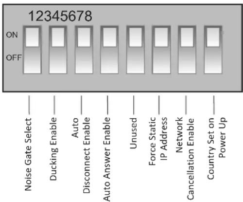
Figure 2-4: Configuration Settings Switches.
Configuration Settings DIP Switches
The SETTINGS switches are used to configure the DHY-04 in the modes that you want it to operate. A label on the top panel of the unit shows the orientation of the switches:
The following paragraphs describe the function of each switch; the default or normal position is shown in curly brackets.
Noise Gate Select - SW1 {ON}
An output noise gate operates when the telephone signal is below the noise gate threshold control. This noise gate reduces the output gain by 34dB during low level signal conditions. This eliminates the effects of telephone line cross talk. The noise gate can be switched off if you don't wish to use it by switching SW1 to the OFF position.
Ducking Enable - SW2 {ON}
This switch allows the received signal to be automatically attenuated by 18dB when both received and sent audio are present in the hybrid. This allows an operator in the studio to talk over the caller at all times.
Auto Disconnect Enable - SW3 {ON}
When SW3 is enabled (ON) the DHY-04 automatically disconnects from the telephone line by detecting the appropriate disconnect regime selected for the specific country according to the selected country code (see Table 2-2).
Line reversal and K-break work by changing the voltage on the line and have parameter settings which indicate a duration range for which this voltage change must be present. Tone detection has a more complicated and extensive parameter set. A variety of single or dual tones with level control are available together with the ability to handle cadence patterns, where known countries disconnect requirements are preset, but if not the ETSI default of 400Hz tone is used. These parameters can be defined to use standard tones or the 'User' sets which are set via the webserver. You may need this capability if your telephone system provides non-standard call progress tones.
Ring Detector (Auto Answer) Enable - SW4 {ON}
This switch enables the integrated ring detector, which automatically answers incoming calls after the number of rings set using the webserver (see page 24, Configuration - Telephone). The default is 2 rings.
Note double cadence ring tones count both rings in the cadence pattern.
Force Static IP Address - SW6 (ON)
When SW6 is enabled (ON) during the unit power-up routines, the Network settings are overridden to force the unit to use a static IP address of 192.168.0.100 with a subnet mask of 255.255.255.0.
Network Cancellation Enable - SW7 (ON)
When switch SW7 is enabled (ON), the DHY-04 performs the echo cancellation routine on the incoming signal from the telephone line. This would be the normal operational setting, but it may be disabled for special circumstances.
Country Set on Power Up - SW8 (OFF)
SW8 is only read on power-up and needs to be ON to set the specific country code to be used for the unit (set ON the remaining switches to define the country code - see Table 2-1 on page 10). After power up, the switches should be returned to their normal position, otherwise the unit may fail to work correctly. The country code can also be changed via the Ethernet port webserver, but in either case when the country setting is altered, any calibration parameters are discarded as they will most likely now be incorrect. These parameters include tuned hybrid impedance settings & coefficients and default cancellation calculation coefficients.
Country Code Selection
The correct country code selection is essential for proper operation of the DHY-04 unit. It ensures that all telephone approval parameters are met for operation of this unit in various parts of the world. The table following is likely to change with additional countries or PABXs and possible detail changes for existing countries. However the actual country codes are fixed and will not alter. For the latest table please refer to our website www.sonifex.co.uk/dhy04
The country codes are selected on power up, by setting DIPSwitch 8 of the SETTINGS on the rear panel to the "ON" position and setting DIPSwitches 1-7 as per the following table or from the Webpage. Once the system has initialised – indicated by the chase pattern of LEDs on the lower bargraph, then all switches should be returned to their previous position for the correct operation of the unit. ETSI, the European Telecommunications Standards Institute (http://www.etsi.org/) govern the telcoms standards used and in the majority of cases, it has been provisionally assumed that the disconnect tones are at the ETSI standard - Code 1 in the following table.
Table 2-1: Supported Disconnect Tone Details by Country. (* - Provisional Disconnect Tone Setting Uses TBR21 default of 400Hz Continuous) The Nortel, ELMEG and PHILIPS settings are for PABXs used in the Netherlands which have non-standard disconnect tones.
The unit can be programmed with other settings, so please contact us if you need the settings for a different country to be implemented. In this case, it would be necessary to have a technical specification of the line conditions, an audio recording or a specification of the disconnect tone parameters (tone, line reversal or K-break).
Connect the earth and mains power connections as per the information given in the Configuration & Controls sections of the handbook. The hybrid unit should be connected with reference to the following diagram.
![graph TD A["Handset"] --> B["Microphone"] C["Telephone Line Ethernet"] --> D["Earth"] E["Remote Divert"] --> F["Remoles"] G["Input to Telephone Channel"] --> H["Output from Mixer Clean-Feed"] I["Power"] --> J["DHY-04 Mixing Desk"] K["Mains Power"] --> L["Power"] M["Line"] --> N["Ethernet"] O["Handse…](/content/2026/05/958589/images/1774708f343e2e1313bfb46eb71b8565ee3b3df6997681f6ba5d1505fde54e3e.jpg)
Figure 3-1: DHY-04 User Connections.
Telephone Line
The telephone line socket is connected to the telephone network using the RJ11 to RJ11 cable provided. An adaptor is provided to connect to a standard BT socket.
Handset
A simple telephone handset can be used to take and make calls when plugged into the equipment handset connector. An adapter is provided if the handset is fitted with a BT plug as standard.
Remote Line Hold
A remote switch may be connected at the Remotes socket in order to control the line connect button from, say, the telco channel of a mixing desk.
Connect the output from the mixing desk "clean-feed" to the mic/line input of the DHY-04, with the mic/line input select switch set to "Line". A clean-feed is a signal produced by a telco module on a mixer which is used as the output to be fed back to a caller on a telephone line. The cleanfeed is a sum of all the other signals which constitute the programme output, except for the caller's audio (this is so that the caller doesn't hear him/herself in the ear-piece). A cleanfeed signal will generally be of a better quality than a mix-minus signal.
Mic/Line Input
The characteristics of the mic/line input are determined by the state of the mic/line configuration selection switch. It is a balanced bridging input and in line mode will accept normal signals at 0dBu peaking to +8dBu from a sound mixer clean feed. In mic mode the unit will accept 200 Ohm microphone level signals with a maximum gain of 74dB. It is suitable for a wide range of microphones and the available gain is 74dB to 40dB, which can be adjusted by the mic level pre-set mounted on the rear panel. The input circuitry to the DHY-04 has a very effective limiter, which will prevent high level overloading problems. Ideally, the maximum input level should not exceed +12dBu. This limiter is used for both line and mic input modes.
XLR Output
Connect the output of the DHY-04 to the telco input of the mixing console. The output connection will deliver a balanced/floating low impedance signal of 0dBm from the telephone line. The output of the digital hybrid unit is normally 0dBu from a balanced source of 50Ω or less across the useful bandwidth of the equipment. The bandwidth is restricted by the line conditions between 250 Hz and 4 kHz. The output stage is capable of driving into 600 Ohm loads at up to +8dBu. Termination of the output is
not necessary however and direct connection can be made into the mixer telephone return channel.
The output stage has a 3-way gain switch control, mounted on the front panel (Level to Line), which may be set to give 0dB signals at the output. In addition, an output noise gate operates when the telephone signal is below the noise gate threshold control. This noise gate reduces the output gain by 34dB under no signal conditions, eliminating the effects of telephone line cross talk.
Isolation of better than 71dB is created between the input and output connectors when the hybrid unit is functioning on an exchange line.
Using The AES/EBU Input & Output
The unit is also capable of working in the digital domain by supplying AES/EBU digital audio into the input XLR. The unit will automatically detect this digital signal and so will change the output to a digital audio signal synchronised to this input. The unit will treat 0dBFS to be the equivalent to a +18dBu analogue signal. The AES lock LED will indicate when a valid AES signal is present. Signals above -6dBFS have AGC applied to limit the internal signal to a maximum of -6dBFS (equiv +12dBu).
Note: The earth bond at the screw terminal must be connected to a technical earth to ensure the safe operation of the equipment under all line conditions.
Using the DHY-04
First Use
Before using the DHY-04 you should ensure that it is connected as figure 3-1 and that the unit is setup for the correct line conditions.
EITHER
- Directly from the webpage select the country code required and press the 'Submit' button
OR
- With the unit powered off set the DIPSwitches of the SETTINGS on the rear panel ON for the appropriate country specification (see Table 2-1, "Country" on page 10).
- Ensure that DIPSwitch 8 is also set ON and then power up the unit. During the power up cycle the new country code should be reflected in the top row of LEDs, on the front panel.
- Now return the DIPSwitches to their default condition – switches 1,2 & 7 ON, with switches 3 & 4 also ON if you wish to use automatic call handling. The unit should now be ready to make & receive calls.
Using the DHY-04 with Internal Telephone Exchanges
The DHY-04 can be configured to operate with internal exchanges, such as the Avaya exchange. Contact technical.support@sonifex.co.uk with details of the exchange and we should be able to program the unit to those particular settings, using the User Set country codes. Typically, most modern exchanges connect to the outside world via digital lines - in this case there is no network echo and switch 7 should be turned OFF.
Receiving a Call
With the equipment connected as in Figure 3-1, calls may be received and detected by the ringer in the telephone handset. To receive the call, lift the handset and establish contact with the caller. The call may be diverted to the telephone hybrid by pressing either the front panel mounted line connect button, by activating the remote port, or via the serial or Ethernet (webpage) ports.
Note: The DHY-04 units have an integrated divert relay that will automatically disconnect the handset when the unit handles the calls.
Incoming calls can be answered manually from the line connect button, or the remote line connect switch, or automatically by enabling the integrated ringing detector (settings SW4 ON), or externally via the serial or Ethernet ports. Ringing tone illuminates the line connect button. The line connect button lamp is off in the non-connected mode and illuminated in the connected mode.
It is recommended that the auto-disconnect feature be used when the ringing detector is enabled.
Note: The remote lamp tally mimics the front panel line connect button lamp, i.e. it flashes when ringing and is on when the line is held.
The hybrid unit now behaves as a 4-wire to 2-wire converter with signal inputs at the mic/line input connector and telephone signal output at the output connector.
The call may be cleared by re-pressing the line connect button, or by means of the remote divert switch, or via the serial or Ethernet ports. The call can also be cleared automatically by enabling the auto-disconnect feature.
With both auto-answer and auto-disconnect in use, call handling can be completely automatic in operation (settings SW3 & SW4 ON).
Integrated Ringing Detector – Auto Answer
Ringing detectors can be used when you need to answer a call automatically, for instance: If a journalist files a report to a recorder over a telephone line, the call can be picked up after a set number of rings by the ringing detector. The DHY-04 has a built in ring detector that is enabled by setting SW4 on the rear panel.
Making a Call
To initiate a call, lift the handset and dial the required telephone number. When the call has been established, press the line connect button and the call will be handed over to the telephone hybrid unit. To clear the line at the end of the call, press the line connect button. The line connect button lamp is off in the non-connected mode and illuminated in the connected mode. The DHY-04 is also capable of making outgoing calls via DTMF dialling by using the serial or Ethernet ports.
If the line is not connected to a valid telephone system (determined by no line voltage present), then trying to connect is invalid. Pressing the line hold button will cause it to flash twice quickly. If the attempt to connect is via the serial port, then the DHY-04 returns an ERR:08 error message.
Using Speed Dial Buttons
There are also 4 Speed Dial buttons on the front panel that can make calls to 7 numbers set up via the webserver. When dialing, the unit shows the dialing by a rotating illumination pattern on these buttons. Speed Dial 1-4 are accessed by a simple press on buttons 1-4, Speed Dial 5-7 and last number redial are accessed by pressing and holding buttons 1-4 respectively.
Call Established
Level Setting
The DHY-04 hybrid operation is optimized for signals around 0dB. The front panel gain switches can adjust the signal levels for both caller and sender. The default position for these switches is receive gain (upper) fully counterclockwise (6dB) and the transmit gain (lower) to be in the middle (0dB). Set the lower switch so that the bargraph normally shows 0dB (second yellow LED) with occasional peak signal levels illuminating showing +6dB (first red LED). If your mixing desk or source audio is only sent at consumer level, then J1 should be fitted on the PCB (See page 5 for details of this).
DTMF Detection
The caller can use this feature in conjunction with auto answer to force external actions from the DHY-04. Once again, in the case of a journalist ringing in a report, they can press a key on the telephone keypad to switch on an external recorder. The key used is set by the value in the webserver (Configuration - Remote page 26). The presence of the DTMF tones in the incoming signal for the chosen key will activate the output on the remote connector.
Integrated Disconnect Detector – Auto Disconnect
The DHY-04 can detect when a call has been dropped by the caller and can release the line. There are a variety of ways that the central exchange
can signal this to remote equipment and the DHY-04 supports the 3 most common methods:
- Momentarily reversing the polarity of the signal (line reversal); • Momentarily shorting the tip & ring (K-break)
- Issuing a tone to the line (tone detect). The method chosen is initially determined by the country code selected, but this can be overridden by using the webserver.
Conference Calls
The DHY-04 has the ability to conference 2 calls on separate DHY-04 units together so that you need only to use 1 telco module on the mixer. These units are linked by a CAT5 cable (wired as shown below) via the RJ45 connectors on the rear of the units. The conference calls record feature is unavailable on the DHY-04.
Note: This is not a standard CAT5, or CAT5 crossover, cable.
Establishing calls on both units will allow each caller to hear a mix of the clean-feed station output and the other caller. The feed to the mixer will contain a mix of both received calls.

Figure 3-2: Conference Port Cable Connections.
The conference port cable simple cross-connects the Conference Input (Phase and Non-Phase) signals to the Conference Output (Phase and Non-Phase) signals respectively. It is available as an accessory, DHY-04CONF.
Using the Conference Port as a Record Output
If you are not using the conference port, it can be used to provide a balanced audio output from the Conference Output Phase and Non-Phase pins. This output will contain just the caller signal unless the webserver option is selected (Configuration-Misc, page 27), which will create a mix of caller and sender on the record output.
Using the Conference Port to Share a Stereo Digital Audio Connection Between Two DHY-04 Units
The DHY-04, when connected to a digital input, has the ability to receive a stereo signal. Normally just the left channel is used for the hybrid, but the unit can be set to use the conference port to feed the right channels to another hybrid, i.e. you can use a stereo signal to feed two hybrids automatically.
Set the first DHY-04 unit to Digital Master Conference mode in the webserver (Configuration-Misc, page 27) and use a crossover wired connection to another DHY-04 which is set to Digital Slave Conference mode (Configuration-Misc, page 27). Now the first unit provides a telco connection via the left channels and the slave unit provides a telco connection via the right channels.
4 Hybrid Technical Description
The hybrid has to be very flexible to maintain its operation for the many different countries' telephony systems. There are 3 main parts to consider: - the electrical interface; the impedance presented by the central exchange; and the actual echo cancellation techniques and algorithms. The country code presets will use a theoretical optimum set of values for the various internal parameters of the unit. However in practice in may be necessary to tune some of the parameters to achieve the best possible results.
Electrical Interface
The telephone system is essentially similar from country to country, but there are small yet significant changes around the globe: e.g. max signal levels, line current limits, ringing conditions etc. These values are preset by the country code selection and can be adjusted via the serial port parameters.
Impedance Matching
The line to the central exchange will present certain impedance to the hybrid, which will mean that the echo response to any signal will be modified according to the frequency and level of that signal. By impedance matching the signal we are able to predict, and therefore subtract, a simple estimation of the echoed signal. The AC impedance and DC impedance parameters can also be both set via the serial port parameters.
Echo Cancellation
The echo part of the returned signal can be expressed in terms of delayed sent signal.
The hybrid coefficients are a measure of the amount of signal that is expected to be echoed from each delay slot (TAP). There are 2 echo cancellation routines running on this unit. The first is a simple 8 TAP unit
running in the telephone interface ICs. It allows the data presented to the DSP to be easily filtered into a signal with caller input and a signal with just sent signal echo. The second filter is a variable length TAP with dynamic adaptation running on the on-board 24bit DSP. The length of this TAP is dependent of the expected delay in any echoes from the central exchange. The default length is 24ms, but the unit is capable of calculating delays up to 250ms.
The adaptation routines constantly adjust the internal DSP coefficients to achieve the best echo cancellation. However the dynamic performance of this algorithm (i.e. the speed that the echo cancellation is optimised) is inversely dependant on the maximum delay (number of TAPs) allowed, so increasing the delay will result in a slightly poorer dynamic performance.
To ensure the best performance after a power on we recommend saving the cancellation coefficients following a successful call. These coefficients will be loaded during the power up cycle and will improve the 'settling' time for the echo cancellation algorithm.
Updating Firmware
The preferable method of communicating with the DHY-04 is to use the Webserver embedded within the DHY-04 Firmware.
The DHY-04 operating software is stored in flash memory and can be overwritten as new code is published. The flash memory is partitioned into boot code, firmware, and saved parameters. Only the firmware partitions are erased so that even in the unlikely occurrence of a power fail during the flash update, the system can still be recovered. If no Firmware file is found, the unit will automatically start the Bootstrap code that contains a minimal webserver allowing the unit to have new code uploaded.
If a firmware file is corrupted, but still seen by the system as valid code then the unit will, most likely, not be able to connect to the integrated
4 Hybrid Technical Description
webserver. In this case you should force a bootstrap mode by powering up or resetting the unit whilst holding down the Line Hold button for 8 seconds. The LEDs show an alternating 2on-2off pattern that switches to a 4on-4off pattern after 8 seconds. Now release the button and connect to the bootstrap webserver either by discovering the unit with the discovery app or by powering up with DIPSwitch 6 set to ON, when the unit will be found at a fixed static IP address of 192.168.0.100.
Select the firmware file to be uploaded – a link to our website is shown to fetch the latest version of code – and then press update. The DHY-04 will reboot when the file transfer is complete.
5 Serial Port Control
Default connection is 19200, e, 8, 1 and using XON/XOFF handshaking.
The serial port has reduced capability compared to the DHY-03 as the setup and firmware functions have been removed and are implemented by an embedded webserver.
SCI Software
Sonifex provide free of charge software, SCI, to allow you to manage connection and control of all aspects of the serial port interface. Go to www.sonifex.co.uk/sci for the latest version.
Serial Interface Commands & Responses
| ANS: - Answer Call - ACK: or NAK: | ||
| BSV: - BootStrap version - BOOT:x.xx.xxx.xxx | ||
| CLR: - Clear Call - ACK: or NAK: | ||
| DTS:nnnn - Send DTMF string nnnn -ACK: or ERR: | ||
| MAC: - MAC Request - returns current MAC address | ||
| NET: - Network Request | - returns active | Network Parameters |
| SER: -Serial Number Request | - SER:nnnnnnnn | |
| TEL:nnnnn | - Make Call | - ACK: or NAK: where nnnnn is tel number string or #n for speed dial numbers (1-7) or #L for redial last number |
| UID: | - Unit ID request - UID:DHY-04 | |
VER: - version request - VER:x.xx.xxx.xxx
| SRQ: - Status Request | - See Below | |
| STA:01 | - Initialisation | |
| STA:02 | - On Hook | |
| STA:03 | - Ringing | |
| STA:04 | - Off Hook - connected to line | |
| STA:05 | - Dialling | |
| STA:06 | - Firmware Update in progress | |
Error Messages
| ERR:01 | - Command Not Found |
| ERR:02 | - Invalid Command (Error Unknown) |
| ERR:03 | - Invalid Command (Invalid Parameter) |
| ERR:04 | - Parameter out of range |
| ERR:05 | - Write Parameter is Read Only |
| ERR:08 | - Line Volts Missing |
| ERR:09 | - Command not allowed when Call is Active |
| ERR:11 | - Command not allowed when Call is Inactive |
The telephone interface parameters are accessible from the webserver for changing the settings for use on non-standard telephone systems or PABXs and would not normally need to be changed on standard systems. They are shown in Appendix A.
Many of these parameters are critical to the correct operation of the DHY-04. Changing them may impact on the correct working of the unit or cause the unit to operate in a way that is outside the telecom approval regimes. Our advice is that the telephone interface parameters should not be changed without detailed technical knowledge or input from Sonifex. Both country code and disconnect type tables have reserved entries for future additions - if you have special requirements for either of these parameters please contact us with details and we can assess the demand and then add to the standard list as required.
6 Webserver
6 Webserver & Network Discovery
In addition to any physical controls the DHY-04 has a built in webserver which can allow you to control and configure the unit remotely through a web browser. The webpage interface also enables you to view status information, alter network settings, and update product firmware.
The Ethernet port should be connected to a network and then the unit will be accessible to all computers on that network - including smartphones/tablets if the network is WiFi compatible.
Connecting to the Device
To connect to the device you will need to know either the unit's IP address or its Bonjour Name. To connect to the device by IP address (eg 192.168.0.100) connect via a browser by entering http://192.168.0.100 in the address bar of the browser.
To connect via Bonjour Name in a Bonjour enabled device enter the name in the browser address bar. The default name is the device ID 'DHY-04', a hyphen character '-' , followed by the serial number without leading zeroes '1234' and then followed by '.local./' to indicate the local domain – so DHY-04-1234.local./
The hostname can be changed to make it more memorable or descriptive of an implementation, however, conflicting names should be avoided.
First Time Usage
The DHY-04 network interface employs Zeroconf networking, meaning that it supports DHCP, AutoIP and MDNS-SD using Bonjour. When you first get the unit it is set to use AutoIP and DHCP. If you have a DHCP on your server simply connect the device to your network and either run the discovery application or ask your network administrator for the assigned IP address. If you have a Bonjour enabled device enter the default name in the browser address bar as above. The nature of DHCP means that the unit is not guaranteed to maintain a fixed IP address each time it is reconnected to the network.
If your system network is unsuitable or doesn't have a DHCP server then the unit will use AutoIP which will poll addresses in the reserved range of 169.254.x.x until it finds an unused address. Unless your network uses this mechanism for IP address assignment, this will most likely be used when connecting a PC with a network cable directly between the unit and the PC. Ensure that the PC has dynamic addressing enabled in its network options and the AutoIP system will ensure that each device has a unique ID in the 169.254.x.x range. Now using the discovery app, find the IP address or if the PC is Bonjour enabled, type in the device name to the browser as above.
Finally if you are still having issues connecting – set DIPSwitch 6 to ON (up) and power cycle the unit. This will force the device to use a static IP address of 192.168.0.100
Once connection is established in a browser go to the Network tab and set the device to the settings appropriate for your network.
MDNS-SD and Bonjour
Bonjour is an application created by Apple and is integral to Apple operating systems and the iTunes app. Bonjour for Windows is available as a plug-in for MS Internet Explorer®. Go to our website or other download stores and download the appropriate version for your operating system.
Sonifex Service Discovery App
This is a free download for Windows from our website- www.sonifex.co.uk/technical/software/index.shtml#sfxsrvdisc
It looks for classes of devices on the network and allows you to connect via a browser to them where appropriate. If Bonjour is installed select the Bonjour tab and then the Sonifex Web Server Service to show all devices. Select the device you wish to connect to, by type and serial number, and then launch to connect via a browser. If Bonjour is unavailable go to the Legacy Discovery tab, press the Refresh button, and if the device has a webserver you can select and launch the device.
Webserver
6
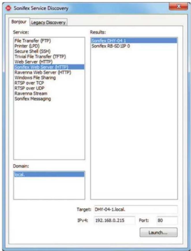
Figure 6-1: Bonjour Service Discovery Page. Figure 6-2: Legacy Service Discovery Page.

6 Webserver

Figure 6-3: Home Page – for basic call control and setting preset calls.
Home Page
The Home Page shows the status of the line, the line hold button, and the various dialing options. Use this screen to change the 7 Speed Dial call numbers.
The Home page is loaded on the first connection to the unit, chosen from the Home Menu dropdown, and after uploading new firmware from the Update screen. While calls are in progress, you can also use this page to send DTMF audio data to the caller.
The Home Page can be protected by setting a password for Level 1 Access. If this is set and the appropriate password has not been submitted, then the default becomes the Device Info page.
Status
Shows the status of the telephone line.
Line
Control to take control of the line in response to incoming ringing or to drop the currently connected call.
The DTMF Send String is defined here, and when the line is connected, it can be sent by the button or by the remote input. A serial command DTS:abcd will also send the DTMF string "abcd" directly.
The 'Save String' button is used to send the string to the unit and save it in local memory. To erase the previously saved string, simply delete the input box content and click elsewhere (a warning message will appear). To set a new DTMF string, just type within the input box and then press the Save String button (or alternately press the enter key).
Dial
Controls to make outgoing calls to previously connected numbers, to a selection of 7 Speed Dials, or to a directly entered number - type the number in the box plus the return key to validate it. Note: a 'w' character in the dial string will cause the dialing process to wait for 1 second and then continue with the remaining characters in the string.
To update the Speed Dials, enter the number and name if required, then press the update button to save the new information.
The number entries should be preceded with the appropriate country codes to support international calling.
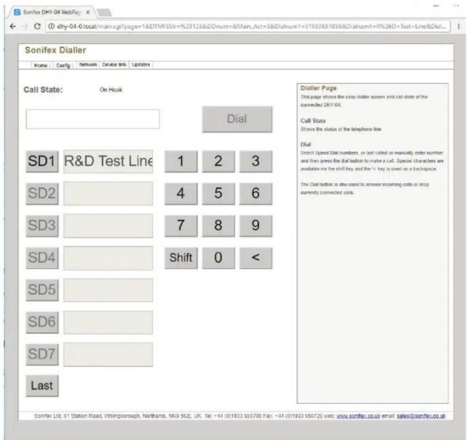
Figure 6-4: Dialler Page – simple screen for making calls – accessed via Home Menu drop-down.
Dialler Page
The Dialler is selected from a drop down of the Home Menu and allows you to remotely dial out from a browser – including smartphones/tablets that are connected by WiFi via an access point to the DHY-04.
This page shows the easy dialler screen and call state of the connected DHY-04.
Call State
Shows the status of the telephone line.
Dial
Select Speed Dial (SD) numbers, or the last called number or manually enter a number and then press the Dial button to make a call.
Special characters are available via the shift key and the '<' key is used as a backspace.
The Dial button is also used to answer incoming calls or drop currently connected calls.
Once a call has been established, the web keypad can be used to send DTMF tones to the line.
6 Webserver

Figure 6-5: Telephone Configuration – selection of telephone interface via Country Code selection.
Configuration - Telephone
The unit configuration is shown as 3 pages – selected from a drop-down in the Config menu. Normally the Show Full Info box is unchecked and the Country Code and Disconnect Settings only show the appropriate drop-down selection. The detailed info about the registers and disconnect parameters are hidden.
Each country code has a Disconnect Set assigned to it, so changing the country code will alter the disconnect settings you may have already selected – the rule here is to select the country code before selecting a disconnect set.
Country Code
Use this option to select the appropriate parameters for many countries. The specific telephone standards required for each country are selected, together with suitable disconnect methods (where known).
There are also a number of special sets for connecting to PSTN systems and finally a User set where the individual parameters can be adjusted to suit particular requirements.
Disconnect Settings
Use this option to change the disconnect method to override the default set for the selected country. There are several methods for recognising disconnect signals - including Line Reverse, K-break and tone detection. The auto-disconnect function is enabled by DIPSwitch 3.
Answer Control
These options allow you to select automatic answering after a defined number of rings and to enable/disable various call control methods.
The auto-answer function is enabled by DIPSwitch 4.

Figure 6-6: Detailed Telephone Configuration and Auto redial warning message selection of telephone interface via Country Code selection with detailed information about the actual parameters being set. This screen is also used to change Individual parameters for User settings.
Auto Redial
The following options will allow the unit to automatically recall either the last dialled number or a specific number, if the call is dropped at the far end.
Enable Auto Redial - Tick this box to enable the auto redial capability. Once enabled, the unit will automatically recall either the last dialled number or the number entered here. Please note that this feature will only work if the correct disconnect method has been selected.
Auto Redial Number - Enter the number that needs to be automatically recalled if disconnected at the far end. Note that if this entry is empty the unit will automatically recall the last dialled number.
To erase the previously saved number, simply delete the Auto Redial Number input box content and click elsewhere, a warning message will appear (as shown in Figure 6-6) then press < > on the pop-up windows and then < > to save the changes.
Buttons
The Copy to User buttons copy the current telephone or disconnect set to the User Set on the DHY-04 unit where they can be edited.
The Submit button saves the selection changes to the DHY-04 and the Reload button retrieves the current set from the DHY-04 unit, losing any changes made locally.
Configuration - Telephone Details
The detailed parameters are shown by selecting the 'Show Advanced Info' check box, which allow you to edit the complete sets of parameter values.
The detailed parameters can be changed by copying the nearest suitable settings to the User setup, selecting User settings in the drop down and then in User mode all the parameters can be edited directly.
Do not change these parameters without careful assessment of the impact to the unit and knowledge of the local regulations.
6 Webserver

Figure 6-7: Remote Port Configuration – settings of remote port and DTMF detection – accessed via Config Menu drop-down.
Configuration-Remote
The second Configuration page sets up the User GPI & GPO pins on the remote port, plus allows the unit to reflect through to the serial port any received DTMF characters from the remote caller. The DTMF detect features will be disabled when sending DTMF strings from the home page option.
On the remote port there are 2 input and 2 output connections. In each case the first ports have predefined functions - effectively mirroring the front panel Line Hold control.
The second port functions can be defined here. Note that the factory supplied options are set to offer the same connectivity as hardwiring of the previous DHY-03 products.
Input Port
Select the functions of the GPI port between the following options :-
Mom/Latch Rem Line Hold - When this input is activated (i.e. connected to ground) the action of the Remote Line Hold input changes from Momentary to Latching mode.
DTMF Start - When this input is activated (i.e. connected to ground) and the unit is connected to a line, then the currently set DTMF String in the Home Page is sent to the line. When this option is selected then the action of the Remote Line Hold is determined by the checkbox below. Note that if you choose to send DTMF from the unit then during that period the DTMF detect circuits are inhibited.
Output Port
Select the functions of the GPO port either as a specific info about ring or call connection or to output the state of the DTMF detection circuit.
Remote Off - remote GPO has no function.
Remote Ring - remote GPO reflects Ring detection.
Remote Connected - remote GPO is active when the unit is connected.
Remote DTMF Detect String - remote GPO is active once the DTMF String below has been detected from the caller.
Remote DTMF Toggle String - remote GPO is toggled every time the DTMF String below has been detected from the caller.
Remote DTMF Follow Hash - remote GPO is active while the DTMF Hash character is detected from the caller.
Remote DTMF Hash Toggle - remote GPO is toggled every time the DTMF Hash character is detected from the caller.
Some networks – especially PABXs - can have short, low level DTMF signalling. The DTMF parameters for Threshold and duration can be set here to account for this. The Threshold defaults to 108 which is approx. equivalent to -12dB and can be decreased/increased for lower/higher level signals. The Duration is the number of tests to be performed, with each test taking slightly over 25ms, so the default of 2 represents a duration of around 51msec. A longer duration will allow for a more consistent result, but requires that the DTMF signal is present for longer. Conversely, a shorter number of tests could have the propensity to generate false positives when audio is present
If you select DTMF Detect/Toggle then set a the DTMF Detect String to a character or string for detection.
Finally the serial port can be made to reflect any DTMF signals directly as they are selected via a DTD:x (DTMF Tone Detect) where x is the DTMF signal detected.
6 Webserver

Figure 6-8: Misc Configuration – extra settings for DHY-04 – accessed via Config Menu drop-down.
Configuration-Misc
The final Configuration page sets up various other options for the operation of the hybrid.
Config Name
Enter the name used to identify the configuration set when saved in 'Updates'.
Description
Enter the name used to identify the device in your studio e.g. Studio1 Telco Ch2.
Echo Duration
Enter the time used in the echo cancellation algorithms. This defaults to 24ms which is more than sufficient for most telephone systems. However the unit is capable of handling line delays of up to 250ms.
Note that longer delays will affect the speed and accuracy of the echo cancellation algorithm.
Conference Port Function
Select the function of the RJ45 conference port from the following :-
Unused - Conference Port has no function.
Conference - Conference Port allows 2 x DHY-04 units to share a single Mixer Telco channel.
Record - Conference Port outputs the caller for recording purposes.
Record Mix - Conference Port outputs a mix of the caller & the mixer send signal for recording purposes.
Digital Share Master - Allows 2 x DHY-04 units to share a digital audio connection by connecting the right hand channel of the digital audio input and output data to the Conference Port.
Digital Share Slave - Retrieves the incoming audio and presents outgoing audio to the Conference Port.
Force Analogue Output
The Main Output of the unit will follow the input type unless this option is selected when the output is always analogue.
Note it is not possible to output digital audio without a digital input being present.
Save Cancellation Coeffs
To tune the system we recommend pre-loading the cancellation coefficients to allow the unit to optimise the speed of the echo cancellation. Use this option to save the current values after a call has been made with good cancellation.
A call to a telephone that has a muted microphone pick-up whilst still sending audio from the DHY-04 is ideal for this.
NOTE: If the DHY-04 settings for Country Code or Echo Length are changed then the coefficients will be cleared.
6 Webserver

Figure 6-9: Password Setting Page.
Password Setting
The Password Setting Page allows you to restrict access to certain pages on the Webserver. Setting Level 1 password protects access to the Home and Dialer Pages, and if the level 2 password is not set it will also restrict access to those pages protected by the level 2 password. Set the level 2 password to restrict access to all the settings pages – i.e. Configuration, Password Setting, Network and Updates. The password requires 5 digits of case-sensitive alphanumeric characters or should be cleared to remove the password protection.
The Automatic Log Out Time is between 0 and 30, where 0 is disabled and 1-30 is the inactivity timeout period in minutes for the Hybrid to automatically log out.

Figure 6-10: Network Page – settings for network interface.
Network Settings
The network page allows you to change the method of IP assignment for the unit and to alter the Hostname used by Bonjour for automatic connection regardless of the IP address assigned.
Note: Submitting new network settings can cause the browser to lose connection. The DHY-04 will attempt to re-connect to the device and most browsers will eventually do this. The process is speeded up by refreshing the page after 15 seconds, but some (notably Internet Explorer) will not respond to this refresh and will require a shut-down and restart, or you should wait a few minutes then refresh the connection.
Bonjour Name
Enter the host name used by Bonjour. The Host name can be up to 63 alphanumeric characters in length, and can include hyphens (-). The default name is the Device ID then '-' then serial number without leading zeroes.
If a conflict occurs on the network this value will be modified to ensure a unique name.
Static IP Address
Enter the static IP address that you wish to assign to this unit. This IP address will be used if Dynamic addressing is disabled. The default static IP address - and the IP address when DIPSwitch 6 is active during power on - is 192.168.0.100
6 Webserver
Static Subnet Mask
Enter the subnet mask of the network you wish to connect to.
The default subnet mask is 255.255.255.0
Gateway IP Address
Enter the gateway IP address of your router.
The default gateway is 192.168.0.1
Dynamic Addressing
Enable dynamic addressing (DHCP or AutoIP) to allow the unit to acquire its IP address automatically from a DHCP server and/or using AUTOIP. Disable both options to use the static IP address entered on this page.
To transfer the new network settings to the connected DHY-04, press the Submit button.
This may require a restart by Internet Explorer and, if the device is being accessed by a direct IP address, you will probably have to enter the new IP address in the address bar.

Figure 6-11: Device Info Page – shows info about the DHY-04 device.
Device Info Page
The Device Info page is self-explanatory as it shows info about the device.
6 Webserver

Figure 6-12: Updates Page – to update the system firmware and load/save configuration files.
Update Firmware Page
The Update page allows you to load new versions of firmware which may be published on the Sonifex Website from time to time. The firmware update may contain small changes like adding a PABX to the country code options, small bug fixes, etc, or may contain major new features. To find out if there is new firmware for this unit, check the Sonifex website.
Generally major features would be indicated by a step in the first firmware version number, whereas small fixes would be only shown in the 'decimal places' or even the build revision.
The device configuration can be saved or loaded from the local PC running the browser. All information about the configuration is saved, but, to allow replication across multiple machines there a few parameters (e.g. IP Address and host name) that are specific to the unit and will not be loaded.
Update Firmware
If an update is available, download the latest version and save the file to your computer. Browse your computer to locate, select the file, and press the Update button. Once the update has started, this page will refresh automatically.
The file must be named according to the following convention "DHY-04" followed by any version or other info then a ".DWN" suffix - e.g "Dhy-04 v2_07 special release.dwn".
Update Config Files
The settings created in the Configuration page can be retrieved from or saved to your computer.
To Load a Config Set, select a file and press Load Config and the options from the config file will be loaded onto the DHY-04 unit.
Just press Save Config to create a file named DHY04.ini in the download directory of the browser. The configuration file is always saved to the download directory as DHY04.ini, but can be edited, renamed or moved to a more convenient location directly on your computer. The file is man-readable and editable. For special setups we sometimes provide a config file to create a special User set to suit customers specific conditions (e.g. non-standard disconnect tone).
Clear Settings
Press this button to clear the settings in the main code. Take care as all settings will be lost - if necessary use the config save to keep a record of settings.
6 Webserver
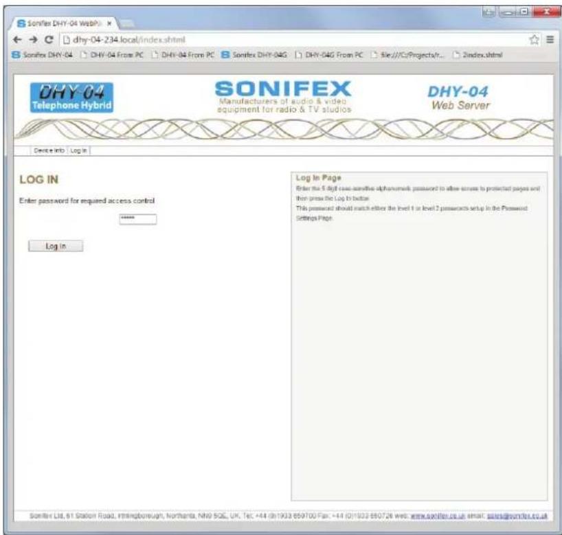
Figure 6-13: Log In Page.
Log In
Enter the 5 digit case-sensitive alphanumeric password to allow access to protected pages. This password should match either the level 1 or level 2 passwords setup in the Password Setting Page.
Once a correct password has been entered access to the appropriate screens will be enabled, until the user selects the Log Out menu or the unit is inactive for the Automatic Log Out Time set in the Password Setting Page.

Figure 6-14: Bootstrap Page.
Bootstrap Mode
This mode is entered when the unit cannot find a valid version of firmware in the flash memory. Alternatively, the bootstrap mode can be forced by holding down the Line Hold button for an extended duration of approximately 8 seconds whilst powering-up the unit. The meter LEDs will flash as alternate pairs until the duration has been achieved, when it will show a set of 4 on/off pattern.
In bootstrap mode the unit can only be used to load new firmware from the web interface or to clear all settings back to the factory defaults. The unit will default to DHCP and AutoIP enabled, in which case use the Sonifex Service Discovery App or check with the administrator of the DHCP server to discover the device IP address.
If DIPSwitch 6 is ON (up) during power up, then the unit will ignore the dynamic addressing options and will use a static IP address of 192.168.0.100
Connect to the device on our browser by typing 'http://' followed by the IP address in the browser address bar – eg 'http://192.168.0.100'. Now you can either press the factory default button to clear the settings to factory defaults or upload a file. To do this choose File button and select the correct download file. Now press the Update button and the unit will accept the new firmware and re-program the flash memory with the new code. The webpage will display an 'Ok' message that will automatically update to the new home page once the program and reset functions are completed. The new firmware will use any previously saved settings.
7 Technical Specification
7 Technical Specification
Audio Specification Analogue Audio I/O
Input Impedance - Line Mode (Clean Feed): 10kΩ balanced 0dB
Input Impedance - Conferencing: 10kΩ balanced 0dB
Input Impedance - Microphone Mode: 2kΩ balanced
Input Level Gain Range: +6dB, 0dB, and -6dB adjusted by 3-position front panel switch, +10dB jumper
Microphone Level Gain Preset: From 65dB to 35dB
Maximum Input Levels: Line +26dBu, mic -24dBu
Clean Feed Limiting Input: -4dBu for CTR21 setting, other values available *
Output Impedance - Line Out: 50Ω balanced floating 0dBu
Output Impedance - Conference/Record: 50Ω balanced floating 0dBu
Output Level Gain Range: +6dB, 0dB, and -6dB adjusted by 3-position front panel switch
Digital Audio I/O
Input Impedance: 110Ω ±20% balanced
Output Impedance: 110Ω ±20% balanced
Sample Frequency Range: 30 - 100kHz (i.e. including 32kHz, 44.1kHz, 48kHz, 64kHz, 88.2kHz & 96kHz)
Signal Level: 2V/7V peak to peak min/max
Analogue Input Level for Full Scale Digits: +18dBU
Telephone Line
Bandwidth to Telephone Line: 250Hz - 4kHz, -3dB ref 1kHz
Telephone Line Impedance: 600Ω, 900Ω plus 14 other complex impedance circuits *
Rejection Ratio: 80-88dB on complex waveforms, reference peak level of 0dBFS
Ring Detector Sensitivity: Off, 1, 2, 3, or 4 rings
Power Supply
Power to DHY-04, S & T Universal 12W power supply: 90 to 250V AC; 47-63Hz;
* These values are dependent on the actual country setting selected on the DHY-04
Connections
Mic/Line/AES-EBU Input: XLR 3 pin female, with push-button mic/line selection
Line/AES-EBU Output: XLR 3 pin male
Telephone Line: RJ11 6/4 socket
Telephone Handset/Instrument: RJ11 6/4 socket
Conferencing or Record Audio: RJ45 socket
Remotes: 9-way D-type socket
Ethernet: RJ45 socket
RS232 Serial: 9-way D-type socket
Power: IEC mains (CEE22)
| Accessories Order Code | Description |
| DHY-04CON | Front Panel Conversion Kit, DHY-04S to DHY-04 |
| DHY-04SCON | Front panel conversion kit, DHY-04 free standing to DHY-04S 19" (48cm) rack-mount front |
| DHY-04TCON | Front panel conversion kit, DHY-04 or DHY-04S, to DHY-04T 19" (48cm) rack-mount front |
| DHY-04CONF | Conference Cable to Connect 2 x DHY-04(G) Units |
7 Technical Specification
| Physical Specification Order Code | Description Height Width Depth* Total Nett | Weight | Total Gross Weight | |||
| DHY-04 (Raw): Automatic digital telephone hybrid, free standing | 4.5cm1.8" | 21.8cm8.6" | 17.5cm6.9" | 1.4kg3lbs | 2.2kg4.8lbs | |
| DHY-04 (Boxed): 6cm | 2.4" | 34cm13.4" | 27cm10.6" | |||
| DHY-04S (Raw): Automatic digital telephone hybrid, rack mounted | 4.5cm (1U)1.8" (1U) | 48.3cm(19" rack width) | 17.5cm6.9" | 1.45kg3.2lbs | 2.3kg5lbs | |
| DHY-04S Boxed): 6.8cm | 2.7" | 58.8cm23" | 27cm10.6" | |||
| DHY-04T (Raw): Twin automatic digital telephone hybrid, rack mounted | 4.5cm (1U)1.8" (1U) | 48.3cm(19" rack width) | 17.5cm6.9" | 2.80kg6.2lbs | 4.4kg9.7lbs | |
| DHY-04T (Boxed) 6.8cm | 2.7" | 58.8cm23" | 27cm10.6" | |||
*Depth is measured from the front to the end of the connectors fitted to the back of the unit.
Approvals Information
Sonifex is a BABT approved manufacturing facility with a license to build telecommunications equipment and all telecom products are compliant with BS6301, BS7002, BS415 and CTR21. The following product description is necessary for BABT approval and provides information on the connection and operating conditions of the units.
Manufacturer
Sonifex Limited, 61 Station Road, Irthlingborough, Northants, NN9 5QE, United Kingdom
Equipment Type
The DHY-04 Telephone Balance Unit is suitable for connection to B.T. exchange lines with a parallel connected telephone at the handset port. The hybrid unit is used as a four wire to two wire converter. Incoming calls received at the handset may be diverted to the hybrid unit and produce a 'telephone' signal at the output of the unit. Signals presented at the input are transmitted to the telephone line only. The DHY-04 automatically balances the telephone line.
Specified Systems
The DHY-04 is suitable for connection to any exchange line forming part of a Public Switched Telephone Network, PSTN, or a Relevant Branch system for PSTN lines or any extension. This equipment is not suitable as an extension to a payphone. A definition of Relevant Branch System for PSTN is given in BS6789: Section 6.1; 1986 Clause 2.9; including the note to that clause.
Ringer Equivalence Number
The REN=1 marking on the rear of this equipment relates to the performance of the apparatus when used in combination with other items of apparatus.
The REN indicates the maximum number of items that should be connected simultaneously to the line. This equipment may be connected with series apparatus up to REN = 4 maximum.
Accessory Ports
Barriered Ports - The Handset series connection complies with BS6301.
Accessory Ports - Mic/Line Input, Main Output, Conferencing Port, Serial Port, Ethernet Port & Remotes
Conditions
This apparatus is not designed for use under controlled conditions of temperature and relative humidity.
Series Connection
When connected into the loop connection between the main apparatus and the PSTN, this apparatus introduces a voltage drop at a current of 40mA of 0.300V.
The apparatus should not be used in conjunction with other series connected apparatus such that the aggregate declared voltage drops, together with that of any relevant wiring at 40mA, exceeds 2.0 volts.
Facilities
This apparatus has been approved for use as a telephone hybrid unit (four wire to two wire converter) and for use with a series connected simple telephone. Any other usage will invalidate the approval of the apparatus if as a result it then ceases to comply with the standards against which approval was gained.
Statutory Mark
Approved for connection to telecommunications systems specified in the instructions for use subject to the conditions set out in them.
8 Appendix 1 - Telephone Registers
Appendix 1 - Telephone Registers
Telephone Interface Register 16
| Name OHS IIRE RZ RT | |||
| Function On Hook Speed Transmit &Receive | Filter type Ringer Impedance | Ring Thresh-old | |
| Value 64 = slow (Australia) | 16 – IIR 2 = synthetic 1 = high |
Table 8-1: Telephone Interface Register 16. (Use sum of required values)
Telephone Interface Register 17
| Name CALZ MCAL CALD OPE | ||||
| Function ADC | Calibration | Manual ADC Calibra-tion | Auto ADC Calibra-tion | Overload Protect |
| Value 128 = Clear Data | 64 = Initiate Calibration | 32 = Disable 8 = Enable | ||
Table 8-2: Telephone Interface Register 17. (Use sum of required values)
Telephone Interface Register 18
| Name RFWE (RNGV=0) RFWE (RNGV=1) | |
| Function Ring Detector Full Wave Rectifier | Ring Detector One shot/Envelope |
| Value 2=Full Wave 2=One Shot | |
Table 8-3: Telephone Interface Register 18. (Use sum of required values)
Telephone Interface Register 22 - parameters 31,56,81,106,131,156,181
| Name | RDLY1 | RDLY0 | RMX |
| Function Ring Delay Bits0 & 1 in 256ms steps | (add value in RDLY2 for total) | Ring Assertion Max Count | |
| Value | 0 = 0 ms; | 64 = 256ms; | 128 = 512ms; |
| 192 = 768ms | 0-63 in 2ms units(0-126 ms) | ||
Table 8-4: Telephone Interface Register 22. (Use sum of required values)
Telephone Interface Register 23 - parameters 32,57,82,107,132,157,182
| Name | RDLY2 | MRTO | RCC |
| Function | Ring Delay Bit 2 | Ring Timeout | Ring |
| Confirmation Count Time | |||
| Value | 128 = 1024ms See | Table See | Table |
Table 8-5: Telephone Interface Register 23. (Use sum of required values).
| RTO Value in Reg | 23 | 0 | 8 | 16 | 24 | 32 | 40 | 48 | 56 |
| Timeout in ms | 80 | 128 | 256 | 384 | 512 | 640 | 768 | 896 | |
| RTO Value in Reg | 23 | 64 | 72 | 80 | 88 | 96 | 104 | 112 | 120 |
| Timeout in ms | 1024 | 1152 | 1280 | 1408 | 1536 | 1664 | 1792 | 1920 |
Table 8-6: Telephone Interface Register 23 - RTO Values.
| RCC Value in Reg | 23 | 0 | 1 | 2 | 3 | 4 | 5 | 6 | 7 |
| Timeout in ms | 100 | 150 | 200 | 256 | 384 | 512 | 640 | 1024 |
Table 8-7: Telephone Interface Register 23 – RCC Values.
Telephone Interface Register 24 - parameters 33,58,83,108,133,158,183
| Name RNGV RAS | ||
| Function Ring Validation Ring Assertion Time | ||
| Value 128 = Enabled | 0-63 in 2ms units (0-126 ms) | |
Table 8-8: Telephone Interface Register 24. (Use sum of required values)
Telephone Interface Register 26 - parameters 34,59,84,109,134,159,184
| Name DCV MINI ILIM DCR | ||||
| Function Tip Ring DC Voltage | Minimum Operational Loop Current | Current Limiting | DC Impedance (50/800 O) | |
| Value 0=3.1V; | 64=3.2V;128=3.35V;192=3.5V | 0=10mA;16=12mA;32=14mA;48=16mA | 2=Enabled (60mA) | 1=800 O |
Table 8-9: Telephone Interface Register 26. (Use sum of required values)
Telephone Interface Register 30 - parameters 35,60,85,110,135,160,185
| Name FULL2 ACIM | ||
| Function Enhanced Full Scale (x2) | AC Impedance | |
| Value 16 = 2 x Full Scale Tx/Rx | See Table 4-12 | |
Table 8-10: Telephone Interface Register 30. (Use sum of required values)
AC Impedance Setting
| ACIM Value Simple | Resistance Series Complex Impedance |
| 0 | 600 O |
| 1 | 900 O |
| 2 | 270 O 750 O || 150 nF |
| 2 | 275 O 780 O || 150 nF |
| 3 | 220 O 820 O || 120 nF |
| 3 | 220 O 820 O || 115 nF |
| 4 | 370 O 620 O || 310 nF |
| 5 | 320 O 1050 O || 230 nF |
| 6 | 370 O 820 O || 110 nF |
| 7 | 275 O 780 O || 115 nF |
| 8 | 120 O 820 O || 110 nF |
| 9 | 350 O 1000 O || 210 nF |
| 10 | 200 O 680 O || 100 nF |
| 11 | 600 O 600 O 2.16 μF |
| 12 | 900 O 900 O 1 μF |
| 13 | 900 O 900 O 2.16 μF |
| 14 | 600 O 1 μF |
| 15 | Global Compromise Impedance Setting |
Table 8-11: Telephone Interface Register 30 - AC Impedance settings.
8 Appendix 1 - Telephone Registers
Telephone Interface Register 31 - parameters 36,61,86,111,136,161,186
| Name FULL | FOH OHS2 FILT | LVFD | |||
| Function Full | Scale Mode | Fast Off Hook Speed2 | On Hook -3c | BFS Filter Pole Select | Line Voltage Force Disable |
| Value 128=Full Scale Mode | 0=512ms;32=128ms64=64ms; | 96=8ms 0=<0.5ms;8=3ms | 0= @ 5Hz; | ||
| 2= @ 200Hz 1=Disable au to switch of Line Voltage to 0v at Low Voltages | |||||
Table 8-12: Telephone Interface Register 31. (Use sum of required values)
Telephone Interface Register 59 - parameters 37,62,87,112,137,162,187
| Name SQ1 & SQ0 RG1 GCE | |||
| Function Spark Qu | enching Receive Gain | in 1 Guarded Clear | Enable |
| Value | 0 = Normal;80=Australian Spec. | 4=Add 1dB Gain to Hybrid | 2=Telephone Inter-face Draws 2.5mA |
Table 8-13: Telephone Interface Register 59. (Use sum of required values)
Notes
SONIFEX
www.sonifex.co.uk
t:+44 (0)1933 650 700
f:+44 (0)1933 650 726
sales@sonifex.co.uk

MADE IN®
BRITAIN


- DHY-04 HANDBOOK
- FOR THE LATEST SONIFEX HANDBOOK INFORMATION PLEASE VISIT THE SONIFEX WEBSITE AT WWW.SONIFEX.CO.UK
- CONTENTS
- DIALLER PAGE 23
- CONFIGURATION - TELEPHONE 24
- CONFIGURATION - TELEPHONE DETAILS 25
- CONFIGURATION - REMOTE 26
- CONFIGURATION - MISC 28
- PASSWORD SETTING 30
- NETWORK SETTINGS 31
- DEVICE INFO PAGE 33
- UPDATE FIRMWARE PAGE 34
- LOG IN 36
- BOOTSTRAP MODE 37
- 7 TECHNICAL SPECIFICATION 38
- APPROVALS INFORMATION 40
- APPENDIX 1 - TELEPHONE REGISTERS 42
- AC IMPEDANCE SETTING 43
- FIGURES
- SONIFEX
- REGISTER ONLINE FOR AN EXTENDED 2 YEAR WARRANTY
- PRODUCT WARRANTY - 2 YEAR EXTENDED
- SONIFEX WARRANTY & LIABILITY TERMS & CONDITIONS
- DEFINITIONS
- WARRANTY
- UNPACKING YOUR PRODUCT
- ITEM
- QUANTITY
- REPAIRS & RETURNS
- CONFORMITY
- ACMA CONFORMITY
- SAFETY & INSTALLATION OF MAINS OPERATED EQUIPMENT
- VOLTAGE SETTING CHECKS
- POWER CABLE & CONNECTION
- CE CERTIFICATION
- CE AND UKCA
- WEEE DIRECTIVE
- ATMOSPHERE/ENVIRONMENT
- 1 WHAT IS A TELEPHONE HYBRID
- THE BEST TELEPHONE HYBRID IN THE WORLD JUST GOT BETTER
- KEY NEW FEATURES OF THE UNIT INCLUDE
- PRODUCT FUNCTION
- TYPICAL APPLICATIONS
- FEATURES
- WHAT IS A TELEPHONE HYBRID
- AVAILABLE FORMATS
- FRONT PANEL CONTROLS
- RESET BUTTON
- SPEED DIAL BUTTONS
- AES/EBU LOCK LED
- LINE HOLD/CONNECT BUTTON
- GAIN SWITCHES (LEVEL TO & FROM THE LINE)
- LED BARGRAPHS
- STATUS & OPERATING MODE INFORMATION
- DHY-04 INTERNAL CONTROLS & ADJUSTMENTS
- JUMPER AND SELECT SWITCHER FUNCTIONS
- REAR PANEL CONTROLS & CONNECTIONS
- AES/EBU & ANALOGUE COMBINED LINE OUTPUT
- MIC/LINE & AES/EBU INPUT
- MIC/LINE INPUT SELECT SWITCH
- ADJUSTING THE MICROPHONE GAIN LEVEL
- REMOTES
- CONFERENCE AUDIO/RECORD OUTPUT
- TELEPHONE HANDSET
- TELEPHONE LINE
- RJ11 TELEPHONE CONNECTIONS
- RS232 SERIAL PORT
- ETHERNET PORT
- MAINS INPUT
- PROTECTIVE EARTH TERMINAL
- CONFIGURATION SETTINGS DIP SWITCHES
- NOISE GATE SELECT - SW1 {ON}
- DUCKING ENABLE - SW2 {ON}
- AUTO DISCONNECT ENABLE - SW3 {ON}
- RING DETECTOR (AUTO ANSWER) ENABLE - SW4 {ON}
- FORCE STATIC IP ADDRESS - SW6 (ON)
- NETWORK CANCELLATION ENABLE - SW7 (ON)
- COUNTRY SET ON POWER UP - SW8 (OFF)
- COUNTRY CODE SELECTION
- HANDSET
- REMOTE LINE HOLD
- MIC/LINE INPUT
- XLR OUTPUT
- USING THE AES/EBU INPUT & OUTPUT
- USING THE DHY-04
- FIRST USE
- EITHER
- USING THE DHY-04 WITH INTERNAL TELEPHONE EXCHANGES
- RECEIVING A CALL
- INTEGRATED RINGING DETECTOR – AUTO ANSWER
- MAKING A CALL
- USING SPEED DIAL BUTTONS
- CALL ESTABLISHED
- LEVEL SETTING
- DTMF DETECTION
- INTEGRATED DISCONNECT DETECTOR – AUTO DISCONNECT
- CONFERENCE CALLS
- USING THE CONFERENCE PORT AS A RECORD OUTPUT
- USING THE CONFERENCE PORT TO SHARE A STEREO DIGITAL AUDIO CONNECTION BETWEEN TWO DHY-04 UNITS
- 4 HYBRID TECHNICAL DESCRIPTION
- ELECTRICAL INTERFACE
- IMPEDANCE MATCHING
- ECHO CANCELLATION
- UPDATING FIRMWARE
- 5 SERIAL PORT CONTROL
- SCI SOFTWARE
- 6 WEBSERVER
- 6 WEBSERVER & NETWORK DISCOVERY
- CONNECTING TO THE DEVICE
- FIRST TIME USAGE
- MDNS-SD AND BONJOUR
- SONIFEX SERVICE DISCOVERY APP
- HOME PAGE
- STATUS
- LINE
- DIAL
- DIALLER PAGE
- CALL STATE
- CONFIGURATION - TELEPHONE
- COUNTRY CODE
- DISCONNECT SETTINGS
- ANSWER CONTROL
- AUTO REDIAL
- BUTTONS
- CONFIGURATION - TELEPHONE DETAILS
- CONFIGURATION-REMOTE
- INPUT PORT
- OUTPUT PORT
- CONFIGURATION-MISC
- CONFIG NAME
- DESCRIPTION
- ECHO DURATION
- CONFERENCE PORT FUNCTION
- FORCE ANALOGUE OUTPUT
- SAVE CANCELLATION COEFFS
- PASSWORD SETTING
- NETWORK SETTINGS
- BONJOUR NAME
- STATIC IP ADDRESS
- STATIC SUBNET MASK
- GATEWAY IP ADDRESS
- DYNAMIC ADDRESSING
- DEVICE INFO PAGE
- UPDATE FIRMWARE PAGE
- UPDATE FIRMWARE
- UPDATE CONFIG FILES
- CLEAR SETTINGS
- LOG IN
- BOOTSTRAP MODE
- 7 TECHNICAL SPECIFICATION
- POWER SUPPLY
- CONNECTIONS
- APPROVALS INFORMATION
- MANUFACTURER
- EQUIPMENT TYPE
- SPECIFIED SYSTEMS
- RINGER EQUIVALENCE NUMBER
- ACCESSORY PORTS
- CONDITIONS
- SERIES CONNECTION
- FACILITIES
- STATUTORY MARK
- 8 APPENDIX 1 - TELEPHONE REGISTERS
- APPENDIX 1 - TELEPHONE REGISTERS
Brand : Sonifex
Model : DHY-04T
Category : Professional audio equipment