
EDU-DI - Electronics kit Radial Engineering - Free user manual and instructions
Find the device manual for free EDU-DI Radial Engineering in PDF.


| Product Type | Passive Direct Box (DIY Kit) |
| Brand | Radial Engineering |
| Model | EDU-DI |
| Audio Connectors | 1x XLR male output, 2x 1/4" TS jacks (input and thru) |
| Transformer | Jensen JT-DB-EPC |
| Switches | 2x push switches (PAD and ground lift) |
| Power | Passive (no external power required) |
| Construction | DIY assembly; includes PCB, components, and metal enclosure |
| Accessories Included | Neoprene non-slip pad, screws, hex nuts, washers, instruction manual |
| Tools Required (Not Included) | Soldering iron (25-40W), side cutters, hex drivers, 7/16" nutdriver |
| Weight | Approx. 1 lb (0.45 kg) |
| Dimensions | Approx. 4.5 x 3.5 x 1.5 in (114 x 89 x 38 mm) |
| Frequency Response | Passive, transformer-coupled; typical 20 Hz - 20 kHz |
| Maintenance | Wipe with dry cloth; avoid moisture |
| Safety | Use proper soldering techniques; handle hot iron with care |
| Spare Parts | All components listed in BOM available from electronic distributors |
| Reparability | User-serviceable; designed for assembly and component replacement |
| Warranty | Limited lifetime warranty (check Radial Engineering for details) |
| Country of Origin | Designed in Canada, made in USA (transformer) and assembled by user |
Frequently Asked Questions - EDU-DI Radial Engineering
User questions about EDU-DI Radial Engineering
0 question about this device. Answer the ones you know or ask your own.
Ask a new question about this device
Download the instructions for your Electronics kit in PDF format for free! Find your manual EDU-DI - Radial Engineering and take your electronic device back in hand. On this page are published all the documents necessary for the use of your device. EDU-DI by Radial Engineering.
USER MANUAL EDU-DI Radial Engineering
Inside you will find all the parts required to build your own EDU-DI. Use this document to assist you as you build your own direct box.

natural_image
Product photo of a passive direct box with electronic components and wiring (no visible text or symbols)Basic Instructions:
- RESISTORS: Start by placing the first resistor (R1) in the designated position. There is no polarity so you may install the resistor in any direction. Bend the wire leads at 90 degree angles to feed the leads through the board. Spread the wire leads slightly to ensure the resistor stays in place. Solder the leads from the bottom of the board, then clip the excess wire leads. Repeat this for the remaining resistors R2-R5.
- CAPACITORS: Place the first capacitor (C1) in the assigned designation. There is no polarity so you may install these in any direction. You do not need to bend the leads to fit, however after it's been inserted you can bend the wire slightly to secure in place. Solder the leads from the bottom of the board and then clip the excess wire leads. Repeat for C2.
- PUSH SWITCHES: Place the first push switch (S1) in the assigned designation. Make sure it is facing outwards from the board, flip the board over and ensure the switch is flush to the board, then solder the 8 pins. You do not need to clip the wire leads. Repeat for the other switch (S2).
Soldering Hints:

natural_image
Illustration of hands using a tool to cut a U-shaped object on a flat surface (no text or symbols)- Mount the component against the PCB surface and bend the wire leads slightly.
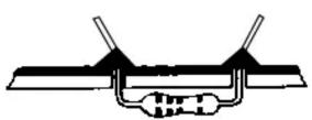
- Solder the wire leads from the bottom, make sure the solder joints are cone-shaped and shiny.
REF QTY Description Color Code
| PCB 1 BARE PCB | |||
| J1 1 XL R MALE JACK | |||
| J2-J3 | 2 TS 14 " JACK | ||
| T1 | 1 12:1 JT-DB-EPC TRANSFORMER | ||
| S1-S2 | 2 PUSH SWITCH | ||
| C1 | 1 0.0uf 100v 10% | ||
| C2 | 1 22uf 25v 20% | ||
| R1 | 1 51R 1/4w 1% | Gn; Br, Br, Gd, Br | |
| R2 | 1 1K8 1/4w 5% | Br; Gy, Rd, Gd | |
| R3 | 1 8K2 1/4w 5% | Gy, Rd, Rd, Gd | |
| R4 | 1 15K 1/4w 5% | Br; Gn, Or, Gd | |
| R5 | 1 6K8 1/4w 5% | Br; Gy, Rd, Gd | |
| Screw Lg | 4 6-32 3/16" | ||
| Screw Sm | 5 4-40 1/4" | ||
Gn=Green, Br=Brown, Gd=Gold, Gy=Grey, Rd=Red, Bk=Black, Bl=Blue, Or=Orange
Tools Required
| Hex Driver for 3/16" screws (Included) |
| Hex Driver for 1/4" screws (Included) |
| Side cutters |
| Nutdriver 7/16" |
| Soldering iron 25-40 watt and solder |
PCB Layout
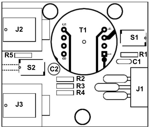
-
Trim excess wire leads as close as possible to the solder joint.
-
14 " TS JACKS: Place J3 in the assigned designation. Make sure the hole is facing outwards from the board, flip the board over and solder two leads on opposite sides of the input jacks to hold it in place. Then apply pressure while reheating the leads so the jack becomes flush with the circuit board. Solder the rest of the pins. You do not need to clip the wire leads for the jacks. Repeat this process for J2.
- TRANSFORMER: Place the Jensen transformer into the T1 designation. Line up the dot on the transformer to the dot on the circuit board, then flip it over and solder it in the same way as the jacks. Solder two leads on opposite sides, then apply pressure to the transformer while reheating the soldered leads so it becomes flush with the board, then solder the rest of the leads. Use the side cutters to clip the excess wire leads.
- INSERTING THE XLR JACK: Position the male XLR connector into the J1 designation so the pins are in the slots.
- MOUNTING THE PCB: Before placing the PC board into the metal insert, push the switches to the "IN" position to allow more clearance and place the two orange washers on each of the 14 " jacks. Now you can position the PC board in place. Using the appropriate hex driver, drive in three of the 3/16" screws to attach the PC board to the metal.
- ATTACHING THE XLR JACK: Slide the XLR jack up so it hangs slightly over the edge of the circuit board. Attach the connector using the remaining two 3/16" screws. Be careful not to overtighten them as you can damage the threading on the XLR. To solder the pins into the slots, flip the EDU-DI upside down and access the PC board by the hole in the bottom of the
metal. Heat up the pin first and then apply a fair amount of solder. Repeat this for each pin.
- SECURING THE TS HEX-NUTS: Insert the two metal hex-nuts into the two plastic black washers so the rounded sides are facing outwards, then using your hands gently screw these into the jacks. Once they are positioned, you can use the 7/16th nutdriver to tighten these (just past the tightness you can do with your fingers).
- SWITCH BUTTONS: Attach the beige button caps to the two switches. Align the cap so that the square lines up, then push it in firmly with either your fingers or a blunt object such as the end of screwdriver.
- ASSEMBLY: Slide the metal insert into the metal wrapper. Ensure that the side of the wrapper that says "LOW-Z OUT" is on the same side as the XLR, and that the side that says "INPUT and "THRU" corresponds with the two jacks. Drive in two of the 14 " screws with the appropriate hex driver. Flip the EDU-DI over, and drive in the remaining two screws.
- NEOPRENE PAD: Remove the white backing from the Neoprene non-slip pad then apply it to the bottom of the EDU-DI, to prevent it from sliding around on a stage or studio floor.
- TEST: Test the EDU-DI by plugging in an instrument into the 14 " input and the XLR output to a PA system or microphone preamp and begin playing. Activate the PAD switch to hear the attenuation work correctly.


Brand : Radial Engineering
Model : EDU-DI
Category : Electronics kit