RocketStor 6618V - Hard Drive Highpoint - Free user manual and instructions
Find the device manual for free RocketStor 6618V Highpoint in PDF.


| Product Type | 8-Bay Thunderbolt 3 Tower RAID Enclosure |
| Number of Drive Bays | 8 |
| Drive Interface | 12Gb/s SAS & 6Gb/s SAS/SATA |
| Host Interface | 40Gb/s Thunderbolt 3 USB-C |
| RAID Levels Supported | 0, 1, 5, 6, 10, 50, JBOD / Non-RAID |
| Dimensions (W x H x D) | 5.77 x 13.83 x 10.24 inches (146.6 x 351.3 x 260.1 mm) |
| Weight | 16.07 lbs (7.29 kg) |
| Power Input | AC 100-240V, 50-60Hz (via included power cord) |
| Hot-Plug Support | Yes |
| Fan Control | Smart control & Manual control |
| Operating Temperature | 5°C to 45°C (41°F to 113°F) |
| Non-Operating Temperature | -40°C to 65°C (-40°F to 149°F) |
| Certifications | CE, FCC, RoHS, REACH, WEEE |
| Warranty | 1 Year |
| Operating Systems Supported | Windows 11/10/Server, macOS 10.13 to 14.x, Linux (Kernel 3.10+) |
| Management Software | Browser-based WebGUI, CLI, API |
| LED Indicators | Power, Present, Active (Blue/Yellow/Red) |
| Alarm Buzzer | Yes (mute button on rear) |
| Advanced RAID Features | Online Capacity Expansion, RAID Level Migration, Storage Health Inspector, Email Notification |
| Included Accessories | 8 drive trays, Thunderbolt 4 cable (1M), UL power cord, mounting screws (35x 3.5", 35x 2.5"), Quick Installation Guide |
| Maintenance & Cleaning | Wipe with dry cloth; avoid liquids. Keep vents clear. Replace failed drives promptly. |
| Reparability & Spare Parts | Drive trays and power supply replaceable; contact HighPoint support for spare parts. |
Frequently Asked Questions - RocketStor 6618V Highpoint
User questions about RocketStor 6618V Highpoint
0 question about this device. Answer the ones you know or ask your own.
Ask a new question about this device
Download the instructions for your Hard Drive in PDF format for free! Find your manual RocketStor 6618V - Highpoint and take your electronic device back in hand. On this page are published all the documents necessary for the use of your device. RocketStor 6618V by Highpoint.
USER MANUAL RocketStor 6618V Highpoint
HighPoint Technologies, Inc.
RocketStor 6614V & 6618V User Manual
natural_image
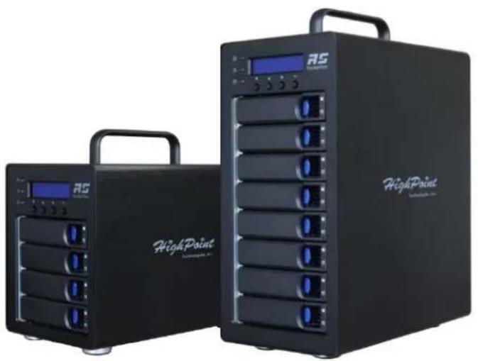
Two black HighPoint 3D server units with multiple RAM slots and a digital display, no visible text or symbols on the devices themselves.V1.00- Nov 17, 2023
Copyright 2023 HighPoint Technologies, Inc.
All rights reserved
Copyright
Copyright © 2023 HighPoint Technologies, Inc. This document contains materials protected by International Copyright Laws. All rights reserved. No part of this manual may be reproduced, transmitted or transcribed in any form and for any purpose without the express written permission of HighPoint Technologies, Inc.
Trademarks
Companies and products mentioned in this manual are for identification purpose only. Productnames or brand names appearing in this manual may or may not be registered trademarks or copyrights of their respective owners. Backup your important data before using HighPoint's products and use at your own risk. In no event shall HighPoint be liable for any loss of profits, or for direct, indirect, special, incidental or consequential damages arising from any defect or error in HighPoint's products or manuals.
Information in this manual is subject to change without notice and does not represent a commitment on the part of HighPoint.
Notice
Reasonable effort has been made to ensure that the information in this manual is accurate. HighPoint assumes no liability for technical inaccuracies, typographical, or other errors contained herein.
FCC Part 15 Class B Radio Frequency Interference statement
This equipment has been tested and found to comply with the limits for a Class B digital device, pursuant to part 15 of the FCC Rules. These limits are designed to provide reasonable protection against harmful interference in a residential installation. This equipment generates uses and can radiate radio frequency energy and, if not installed and used in accordance with the instructions, may cause harmful interference to radio communications. However, there is no guarantee that interference will not occur in a particular installation. If this equipment does cause harmful interference to radio or television reception, which can be determined by turning the equipment off and on, the user is encouraged to try to correct the interference by one or more of the following measures:
• Reorient or relocate the receiving antenna.
- Increase the separation between the equipment and receiver.
- Connect the equipment into an outlet on a circuit different from that to which the receiver is connected.
- Consult the dealer or an experienced radio/TV technician for help.
Modifications not expressly approved by the manufacturer could void the user's authority to operate the equipment under FCC rules.
This device complies with part 15 of the FCC Rules. Operation is subject to the following two conditions: (1) this device may not cause harmful interference, and (2) this device must accept any interference received, including interference that may cause undesired operation.
European Union Compliance Statement
This Information Technologies Equipment has been tested and found to comply with the following European directives:
• European Standard EN55022 (1998) Class B
• European Standard EN55024 (1998)
Table of Contents
Product Overview 7
Kit Contents....7
RocketStor 6614V Kit Contents .... 7
RocketStor 6618V Kit Contents .... 7
Feature Specifications 8
Step 1: Install the RocketStor 6614V/6618V .... 10
Step 2: Install/Update Drivers....12
For Windows Users....12
For Mac Users 13
For Linux Users.... 17
Uninstall Drivers 18
For Windows Users....18
For Mac Users 19
For Linux Users....19
Step 3: Install HighPoint RAID Management Software (WebGUI & CLI) 20
For Windows Users....20
For Mac Users 21
For Linux Users.... 21
Uninstall HighPoint RAID Management (WebGUI & CLI) 23
For Windows Users 23
For Mac Users 24
For Linux Users....24
Step 4A: Login WebGUI 25
For Windows/Mac Users 25
For Linux Users.... 25
Step 4B: Login CLI 26
For Windows Users....26
For Linux Users.... 26
Step 5A: Create RAID Arrays using WebGUI 27
For Windows, Mac and Linux Users 27
Step 5B: Create RAID Arrays using CLI 29
For Windows and Linux Users 29
Step 6: Initialize and format the RAID Array .... 30
For Windows Users....30
For Mac Users 31
For Linux Users....32
Step 7: Manage your RAID array .... 33
RAID Spare Pool 33
Add/Remove Spare Using WebGUI.... 33
Email Notifications 35
SMTP settings.... 35
Adding Email Recipients 37
WebGUI Remote Login 38
For Windows Users 38
For Mac Users 38
For Linux Users....39
Storage Health Inspection (SHI) 40
Enabling SMART Monitoring 40
Disabling SMART monitoring 41
Storage Health Inspector Scheduling 42
RAID Expansion (OCE/ORLM) 44
OCE – Online Capacity Expansion...... 44
ORLM – Online RAID Level Migration 44
Troubleshooting – Hardware.... 47
Enclosure Mute Button....47
LED Activity 47
Table 1. LED Status Information 47
Table 2. LED Diagrams ...... 47
Replacing a Failed Disk 48
Troubleshooting - Software 49
Troubleshooting – RAID....50
Critical Arrays....50
Rebuild failed....51
Critical array becomes disabled when faulty disk was removed 51
Disabled Arrays 52
Recover with RAID Maintenance....52
Recover RAID with Recover Tab 53
Online Array Roaming 54
Appendix A: Navigating the HighPoint WebGUI....55
Appendix A-1: Global View Tab.... 56
HBA Properties....56
Storage Properties 56
Appendix A-2: Physical Tab 57
Controller Information 57
Physical Devices Information 58
Rescan 58
Appendix A-3: Logical Tab 59
Create Array 60
Normal Status 62
Critical Status 62
Disabled Status 63
Delete Array 64
Logical Device Information....65
Physical Device Information....65
Spare pool 66
Add/Remove Spare Using WebGUI.... 66
Rescan 67
Beeper Mute 67
Appendix A-4: Setting Tab 68
System Settings....69
Password Setting 70
Changing your WebGUI password....70
Recovering your HRM password 70
Email Setting 71
SMTP settings 71
How to Add Recipients....72
Appendix A-5: Recover Tab 73
How to Backup your Recover List....73
How to Reload your Backup Recover List 74
Appendix A-6: Event Tab 75
Table 3. Event Log Icon Guide ...... 75
Appendix A-7: SHI (Storage Health Inspector).... 77
Appendix A-8: Help 78
Online Help 78
Diagnostic View 78
Log Saving....79
Appendix A-9: Logout 80
Appendix B: WebGUI Icon Guide 81
Appendix C: RAID Level Reference Guide1....83
HighPoint List of Recommended Hard Drives 84
Resource....84
Customer Support 85
Product Overview
The RocketStor 6618V and 6614V are 4-Bay/ 8-Bay 40Gb/s Thunderbolt™ 3 Tower RAID Enclosures are ideal for I/O intensive applications that require consistent transfer performance and high levels of data redundancy.
RocketStor 6614V and 6118V enclosures can be easily integrated into any PC or Mac platform with Thunderbolt™ 3 USB-C connectivity.
Kit Contents
Before getting started, check to see if any items are missing, damaged, or incorrect. For any discrepancy contact your reseller or go to https://www.highpoint-tech.com/support-and-services for online support.
RocketStor 6614V Kit Contents
• 1x 4-Bay Enclosure
- 4x 3.5 Inch Drive Trays
• 1x 40Gb/s Thunderbolt™4 1M cable
- 1x UL Power Cord
• 20x 3.5" HDD mounting screws
• 20x 2.5" SSD mounting screws
• 1x Quick Installation Guide
RocketStor 6618V Kit Contents
• 1x 8-Bay Enclosure
- 8 x 3.5 Inch Drive Trays
• 1x 40Gb/s Thunderbolt™4 1M cable
- 1x UL Power Cord
• 35x 3.5" HDD mounting screws
• 35x 2.5" SSD mounting screws
• 1x Quick Installation Guide
Feature Specifications
| RocketStor 6614V | RocketStor 6618V | |
| Feature Specifications | ||
| Description | 4-Bay Thunderbolt 3 Tower RAID Enclosure | 8-Bay Thunderbolt 3 Tower RAID Enclosure |
| Port Type | 2x ThunderboltTM 3 USB-C | |
| Number of Drives | 4 | 8 |
| Drive interface | 12Gb/s SAS & 6Gb/s SAS/SATA | |
| Drive Form Factor | 3.5" or 2.5" SSD or HDD | |
| Hot-Plug Support | Yes | |
| Host Interface | ThunderboltTM 3 40Gb/s | |
| Fan control | Smart control & Manual control | |
| Enclosure Dimensions | 5.80" (W) x 9.12" (H) x 10.24" (D) | 5.77" (W) x 13.83" (H) x 10.24" (D) |
| Enclosure Weight | 13.09 lbs. | 16.07 lbs. |
| Warranty | 1 Year | |
| Daisy Chain Features | Supports Daisy Chain connections of up to six ThunderboltTM devices.Notes:The Daisy Chain will end if connected to a USB or Display device via USB-CRAID5 & 6 configurations are not supported by Daisy Chain configurationsFor optimal performance, the enclosure should be connected directly to the host's ThunderboltTM 3 port | |
| Supported Systems | ||
| Operating System | Windows 11, 10Windows Server 2022, 2019, 2016Microsoft Hyper-VOnly supports 64 bit operating system. | |
| Only supports 64 bit operating system.Linux Driver can be installed via internet/network connectionLinux (Support Linux Driver auto Compile)Redhat/Ubuntu/Debian/Fedora/Proxmox/Rocky Linux (Kernel 3.10 and later)macOS 10.13 ~ macOS Sonoma 14.x | ||
| Storage Configuration | ||
| RAID Support | 0, 1, 5, 6, 10 and JBOD / Non-RAID | 0, 1, 5, 6, 10, 50 and JBOD / Non-RAID |
| TRIM RAID Support | Non-RAID, JBOD, RAID 0, RAID 1, RAID10(Supported by Linux, not supported for Windows or macOS) | |
| Boot RAID | No | |
| Data RAID | Yes | |
| Advanced RAID Features | |
| Storage Health Inspector | |
| Redundant RAID Configurations | |
| Multiple RAID Partitions supported | |
| Online Array Roaming | |
| Online RAID Level Migration (ORLM)(not supported by macOS) | |
| Online Capacity Expansion (OCE)(not supported by macOS) | |
| RAID Quick Initialization for fast array setup | |
| Global Hot Spare Disk support | |
| Disk Format compatible: 512, 512e, 4Kn | |
| Automatic and configurable RAID Rebuilding Priority | |
| Auto resume incomplete rebuilding after power on or reboot system | |
| Automatic remap and repair of bad blocks for RAID configurations (HDD)RocketStor 6614V Redundant RAID Levels (RAID1, RAID10, RAID5, RAID6)RocketStor 6618V Redundant RAID Levels (RAID1, RAID10, RAID5,RAID50, RAID6)Write Back and Write Through | |
| Spin down Massive Arrays of Idle Disks support | |
| Native Command Queuing | |
| SAS TCQ | |
| Disk media scan and repair | |
| Staggered Drive Spin Up | |
| Storage Configurations Support Details(Direct Attached) | |
| Storage Monitoring and Management Suite | |
| Browser-Based management tool | |
| CLI (Command Line Interface- scriptable configuration tool) | |
| API package | |
| Drive LED Indicator: Power, Present, Active | |
| SMTP Email Alert Notification | |
| Alarm Buzzer | |
| Operating Environment | |
| Temperature | (operating) 5°C – 45°C(non-operating) -40°C – 65°C |
| Certification | CE FCC RoHS REACH WEEE |
Step 1: Install the RocketStor 6614V/6618V
The following instructions describe how to install your RocketStor 6614V/6618V for use.
Important: Before installing the RocketStor 6614V/6618V, ensure your system is powered OFF.
Take the RocketStor 6618V as an example.
- Place the RocketStor 6618V on a level surface and remove each drive tray.
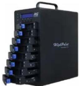
natural_image
Black industrial electronic device with multiple ports and a control panel (no visible text or symbols)- Carefully insert the SSD or HDD into the drive tray and secure it with the provided mounting screws.
1). For 3.5-inch drive: use black screws to secure the drive to each side of the drive tray.
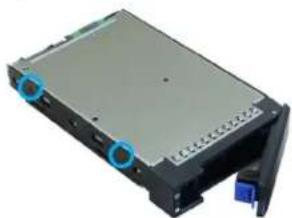
natural_image
3D rendering of a gray rectangular electronic device with blue connectors and a blue connector (no visible text or symbols)2). For 2.5-inch drive: use silver screws to secure the drive to the back of the drive tray.
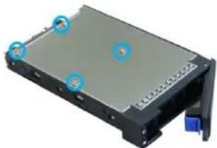
natural_image
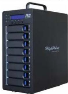
3D rendering of a rectangular electronic device with mounting holes and a blue indicator button (no text or symbols visible)- Install each drive tray into the Enclosure.
natural_image
Black HighPoint 3D printer with multiple ports and a digital display (no visible text or symbols on the device body)- Connect the Enclosure to the host system using the included Thunderbolt™4 cable.

natural_image
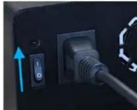
Close-up of a black USB cable inserted into a device's rear panel, showing port and socket (no text or symbols visible)- Connect the Power cable to the rear of the Enclosure and connect it to an AC power source.
natural_image
Close-up of a black electrical plug with a blue arrow pointing to the switch (no text or symbols visible)- First switch on the Enclosure power switch (switch to the " | " position) to power up the Enclosure, then power up the host system.

natural_image
Black RS server rack with multiple ports and a digital display (no visible text or symbols)Note: The RocketStor 6614V/6618V connects to the host system via a Thunderbolt™ cable. As a result, the RocketStor 6614V/6618V will automatically power on when the host system is powered on, and power off when the host system is powered off.
Step 2: Install/Update Drivers
Drivers provide a way for your operating system to communicate with your new hardware. Updating to the latest drivers ensures your product has the latest performance, stability, and compatibility improvements. Drivers are updated regularly.
For Windows Users
- Download the latest driver files from our website.
- Extract the downloaded files onto your PC and note the location of the files.
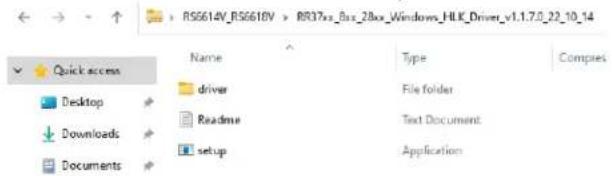
Note: The Driver Software revision shown in the screenshots may not correspond with current software releases. Please make sure to download the latest Driver Software updates from the product's Software Updates page.
- Double click setup to start installing the driver.
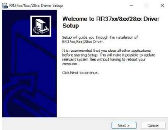
- Click Next and wait for the automatic installation to complete.
- Reboot for changes to take effect.
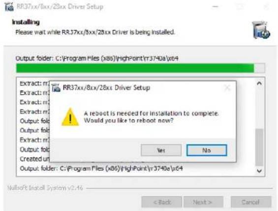
For Mac Users
- Download the latest driver files from our website and locate the download.
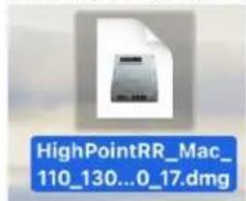
Note: The Driver Software revision shown in the screenshots may not correspond with current software releases. Please make sure to download the latest Driver Software updates from the product's Software Updates page.
- Double click the driver package to start installation (.pkg file).
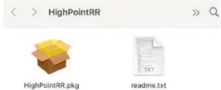
- Click the Continue button.
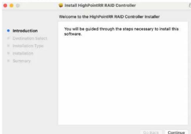
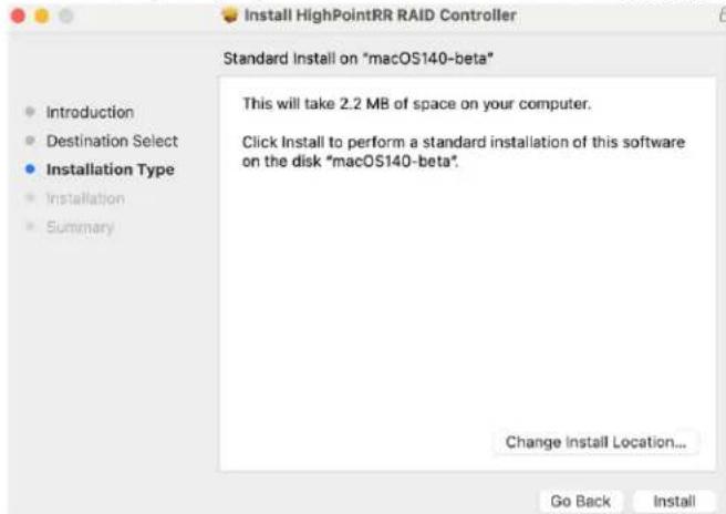
- macOS will prompt you to install the driver. Click Install to proceed.
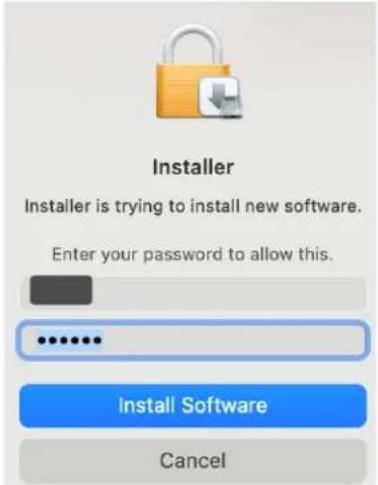
- You will be prompted that installer is trying to install new software, enter the Administrator Username and Password. Once these have been entered, Click Install Software.
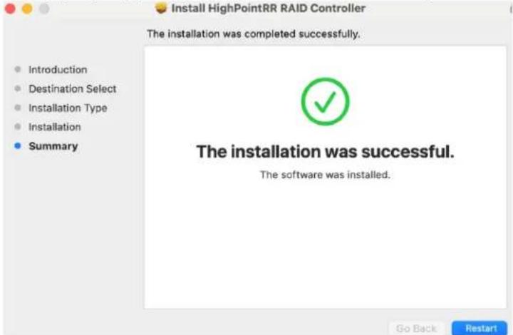
- If no pop-ups appear, please proceed to the next step of installation. Click Restart.
- If you receive a popup window prompting you for permission, click Open Security Preferences.
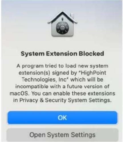
- Make sure App Store and identified developers is checked, and then click Allow.
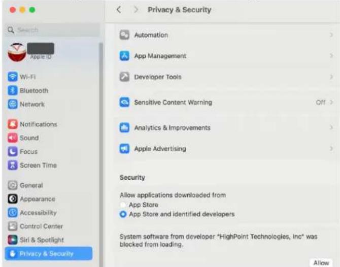
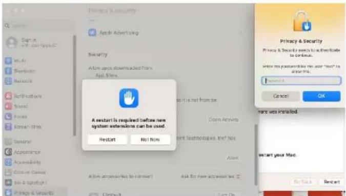
- You will see a popup window, prompting you to restart. Enter the Administrator Username and Password and click Restart.
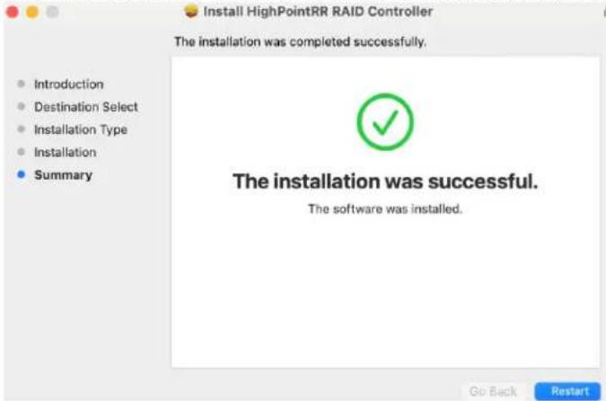
- Return to the driver installation window. Click Restart to restart the system.
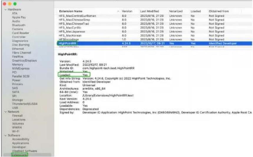
- After the system restarts, the driver's status can be viewed under System Information→Extensions; The following screenshot shows the HighPointRR driver has been loaded.
Note: The driver revision shown in the screenshots may not correspond with current software releases. Please make sure to download the latest driver updates from the product's Software Updates page.
For Linux Users
- Download the latest driver files from our website.
- Open a terminal and go to the directory where the drive package is located.
- Use root permissions to extract the driver package.
tar zxvf RR37xx\_8xx\_28xx\_Linux\_X86\_64\_Src\_vx.x.x\_xx\_xx\_xx.tar.gz
root@t-desktop:/home/t/Desktop/RS6614V_RS6618V# tar zxvf RR37xx_8xx_28xx_Linux_X86_64_Src_v1.23.13_23_01_16.tar.gz
rr37xx_8xx_28xx_linux_x86_64_src_v1.23.13_23_01_16.bin
README
Note: The Driver Software revision shown in the screenshots may not correspond with current software releases. Please make sure to download the latest Driver Software updates from the product's Software Updates page.
- Run the .bin file to install the driver package.
sh rr37xx\_8xx\_28xx\_linux\_src\_vx.x.x\_xx\_xx.xx.bin
root@t-desktop:/home/t/Desktop/RS6614V_RS6618V# ./rr37xx_8xx_28xx_linux_x86_64_s
rc_v1.23.13 23 01 16.bin

Verifying archive integrity... All good.
Uncompressing RR3740A/840A Linux Open Source package installer.....
Checking and installing required toolchain and utility ...
Found program make (/usr/bin/make)
Found program gcc (/usr/bin/gcc)
Found program perl (/usr/bin/perl)
Found program wget (/usr/bin/wget)
Synchronizing state of hptdrv-monitor.service with SysV service script with /lib/systemd/systemd-sysv-install.
Executing: /lib/systemd/systemd-sysv-install enable hptdrv-monitor
update-rc.d: warning: enable action will have no effect on runlevel 1

SUCCESS: Driver rr3740a is installed successfully for kernel 5.15.0-67-generic.
Driver rr3740a is installed successfully for kernel 5.15.0-88-generic.
Please restart the system for the driver to take effect.
If you want to uninstall the driver from the computer, please run hptuninrr3740a to uninstall the driver files.
- The driver will be loaded automatically after reboot.
Note: The installer requires super user's permission to run the installation. So if you are not logged in as root, please supply the password of root to start the installation.
Uninstall Drivers
For Windows Users
- Power down the system and remove the RS6614V/6618V from the motherboard.
- Power on the system and boot Windows.
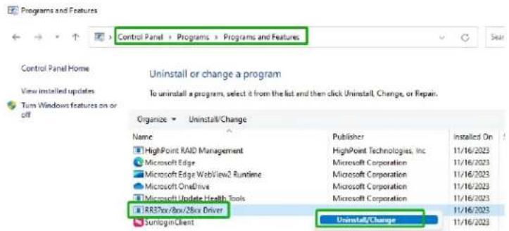
- Access Control Panel and select Programs > Programs and Features, and click on the RR37xx/8xx/28xx Driver entry.
- Click Uninstall/Change.
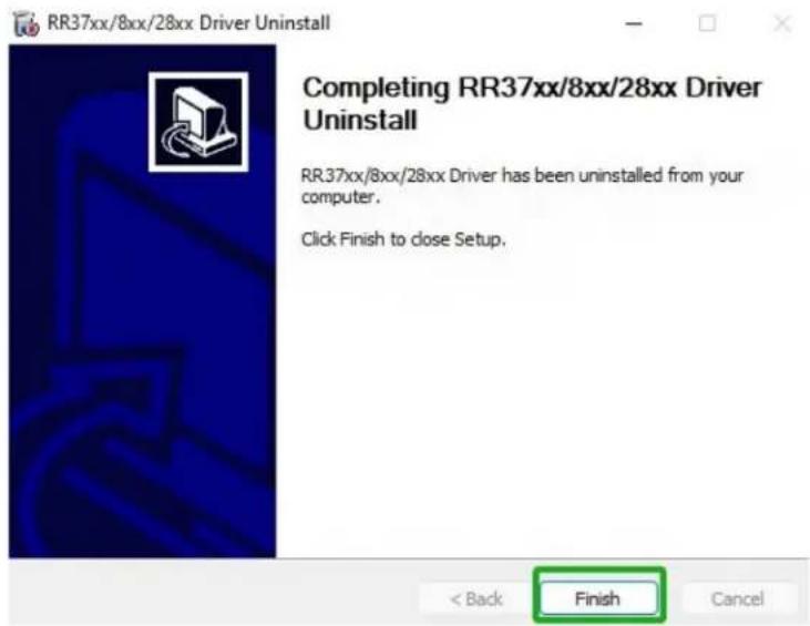
- After uninstalling the driver, click Finish.
For Mac Users
-
Open a terminal and enter Administrator Privileges.
-
Enter the command:
<h1 id="cd-libraryextensions">cd /Library/Extensions/</h1>
<h1 id="rm-rf-highpointirrkext">rm -rf HighPointIRR.kext/</h1>
[tdest@tdests-MacBook-Pro-2018-120 ~ % sudo su
[sh-3.2# cd /Library/Extensions/
[sh-3.2# rm -rf HighPointRR.kext/
- Restart your computer when prompted to complete the process of uninstalling the driver.
For Linux Users
-
Open a terminal and enter Administrator Privileges.
-
Enter the command:
<h1 id="hptuninrr3740a">hptuninrr3740a</h1>
root@t-desktop:/home/t/Desktop# hptuninrr3740a
- Press "Y" to confirm.
Are you sure to uninstall the driver rr3740a from system? (Y/n): y All files installed have been deleted from the system.
- Restart your computer when prompted to complete the process of uninstalling the driver.
Step 3: Install HighPoint RAID Management Software (WebGUI & CLI)
The HighPoint RAID Management Software (WebGUI and CLI utilities) are used to create, maintain, and view your RAID arrays hosted by the RS6614V/6618V. Download the latest software package from the HighPoint website.
For Windows Users
- Download the latest HighPoint RAID Management Software from our website.
- Extract and open the contents of the downloaded file.
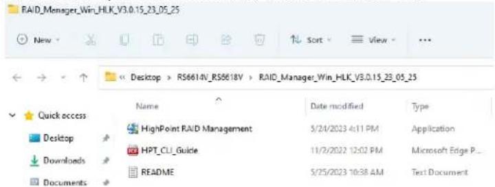
Note: The HighPoint RAID Management Software revision shown in the screenshots may not correspond with current software releases. Please make sure to download the latest HighPoint RAID Management Software updates from the product's Software Updates page.
3. Double-click HighPoint RAID Management.exe.
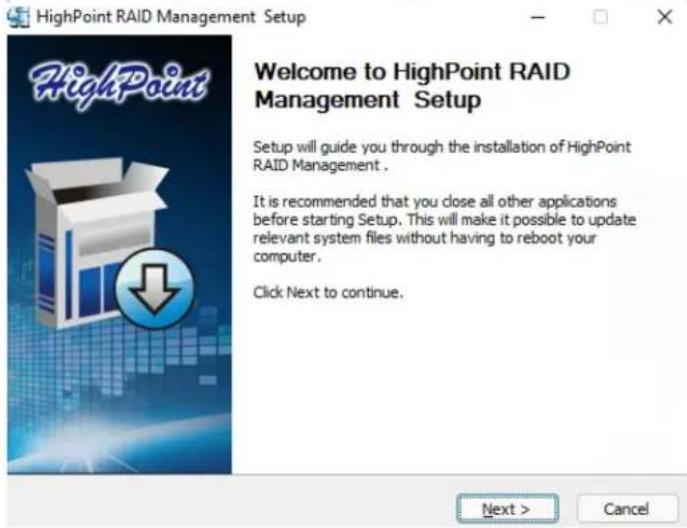
- Follow the on-screen instructions to complete the HighPoint RAID Management Software installation.
- Double-click the HighPoint RAID Management desktop icon to start the WebGUI. Alternatively, type http://localhost:7402 in your browser address bar.
For Mac Users
- Download the latest HighPoint RAID Management Software from our website.
- Double Click the downloaded the HighPoint RAID Management Software file.
Note: The HighPoint RAID Management Software revision shown in the screenshots may not correspond with current software releases. Please make sure to download the latest HighPoint RAID Management Software updates from the product's Software Updates page.
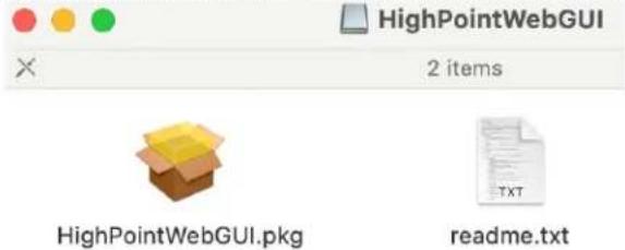
- Double click the HighPointWebGUI.pkg to start the HighPoint RAID Management Software installation.
- Follow the installer on-screen instructions to complete the HighPoint RAID Management Software installation.
- Double-click the HighPoint RAID Management desktop icon to start the WebGUI.
Note: macOS only supports WebGUI.
For Linux Users
- Download the latest HighPoint RAID Management Software from our website.
- Start Terminal and navigate to the downloaded files.
- Using the system terminal with root privileges, browse to the directory where the software download, and enter the following commands to extract the management software package:
# tar zxvf RAID_Manage_Linux_vx.x.x_xx_xx_xx.tar.gz

Note: The HighPoint RAID Management Software revision shown in the screenshots may not correspond with current software releases. Please make sure to download the latest HighPoint RAID Management Software updates from the product's Software Updates page.
- Install the HighPoint RAID management software (WebGUI & CLI) using the following command:
./RAID_Manage_Linux_vx.x.x_xx_xx_xx.bin
root@t-desktop:/home/t/Desktop/RS6614V_RS6618V# ./RAID_Manage_Linux_v3.1.13_22_1
2_05.bin
Remove old hpt_install.log.
Install ......
Package readline lib is already installed!
readline/hptsvr_3.1.13_amd64.deb will be installed!
Selecting previously unselected package hptsvr.
(Reading database ... 182974 files and directories currently installed.)
Preparing to unpack .../hptsvr_3.1.13_amd64.deb ...
Unpacking hptsvr (3.1.13) ...
Setting up hptsvr (3.1.13) ...
Starting hptsvr daemon.
Clean ......
Finish ......
....
Uninstall HighPoint RAID Management (WebGUI & CLI)
For Windows Users
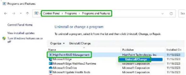
- Access Control Panel and select Programs→Programs and Features, and right-click on the HighPoint RAID Management entry.
- Click Uninstall/Change.
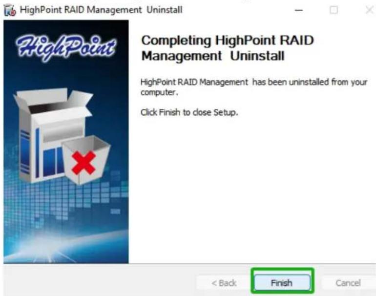
- After uninstalling the HighPoint RAID Management, click Finish.
For Mac Users
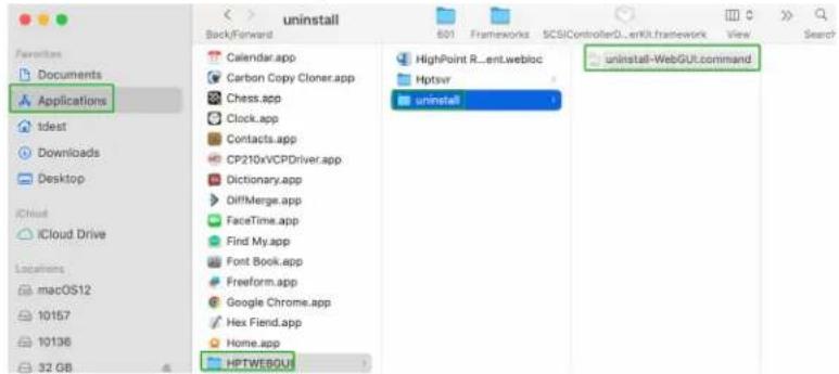
- Navigate to /Applications/HPTWEBGUI/uninstall.
- Click on the uninstall script.
- Type in the Administrator password when prompted.

Note: You must be logged on as an administrator to uninstall the software. The script will prompt you for an administrator password.
If prompted for a password please enter your administrator password.
The following service files will be deleted
    /Applications/HPTWEBGUI
    /Library/Receipts/wwwfiles.pkg
    /Library/Receipts/webservice.pkg
    /Library/LaunchDaemons/HPTWebGUIDaemon.plist
    /usr/share/hpt
    /usr/bin/hptdaemonctl
Process has completed.
Saving session...
...copying shared history...
...saving history...truncating history files...
...completed.
For Linux Users
- Open the system terminal with root privileges. Enter the following commands to uninstall the RAID Management:
dpkg -r hptsvr (or rpm -e hptsvr-https)
root@t-desktop:/home/t/Desktop# dpkg -r hptsvr
(Reading database ... 183129 files and directories currently installed.)
Removing hptsvr (3.1.13) ...
- Enter the following command to check if the RAID Management has been removed successfully: #hptraidconf
root@t-desktop:/home/t/Desktop# hptraidconf
hptraidconf: command not found
Step 4A: Login WebGUI
The Web-based Management Interface (WebGUI), is a simple, and intuitive web-based management tool available for Windows/Linux/macOS operating systems. The Wizard-like Quick Configuration menu allows even the most novice user to get everything up and running with a few simple clicks.
For Windows/Mac Users
- Double click the Desktop ICON to start the software using the system's default web browser. It will automatically log-in to the WebGUI.
- The password can be set after the first log-in. To change the password, select Setting>Password Setting from the menu bar.
For Linux Users
- Enter http://127.0.0.1:7402 or localhost:7402 into the browser to log into the WebGUI, 7402 is the WebGUI's Port Number, which can be modified.
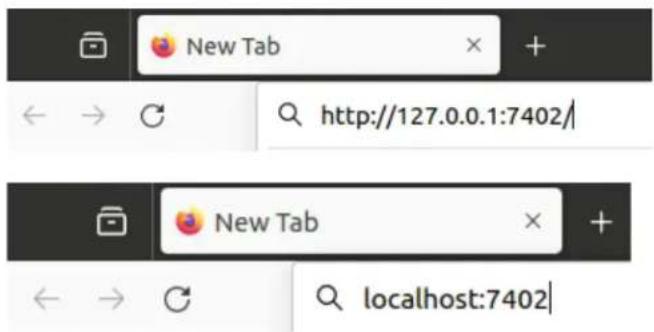
- The password can be set after the first log-in. To change the password, select Setting>Password Setting from the menu bar.
Step 4B: Login CLI
The CLI (command line interface) is a powerful, text-only management interface designed for advanced users and professional administrators. The universal command lines available for Windows/Linux operating systems, and are shared across our entire product line. Comprehensive user guides are available for the CLI, and are included with the most recent product updates available from the Software Updates section of the product category webpages.
For Windows Users
- Method1: Run "Command Prompt" as Administrator and enter hptraidconf and press Enter.
Administrator: Command Prompt
![Microsoft Windows [Version 10.0.18363.778] (c) 2019 Microsoft Corporation. All rights reserved. C:\Windows\system32>hptraidconf](/content/2026/05/958467/images/6cc7d0fdf989ae89773afa53bdd331ec992062033eaddb169bdacc41d77de73d.jpg)
hptraidconf
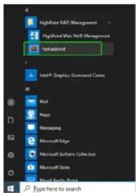
- Method2: Click "Start" to find the HighPoint RAID Management folder, and click on hptraidconf.
For Linux Users
- Open "Terminal" and enter root permissions.
- Then execute the command "hptraidconf" to enter the CLI.
![root@t-desktop: /home/t/Desktop t@t-desktop:~/Desktop$ sudo su [sudo] password for t: root@t-desktop:/home/t/Desktop# hptraidconf](/content/2026/05/958467/images/1a838b2dff58a166785826f5bff1229d4e6d2b8eb85f182ef85f7762407d23c6.jpg)

Step 5A: Create RAID Arrays using WebGUI
For Windows, Mac and Linux Users
- Open the WebGUI.
- Select the proper controller from the drop down on the top left.
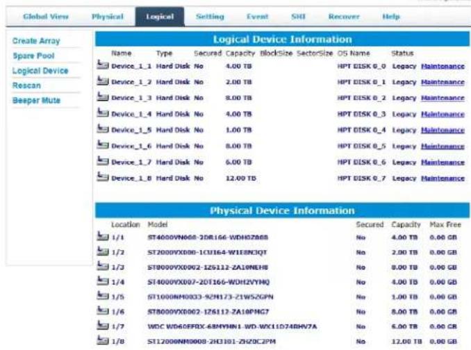
- Click the Logical tab.
Controller(1) RS6618V
HighPoint Technologies, Inc.
- Click Create Array.
Controller(1): R96610V
HighPoint Technologies, Inc.
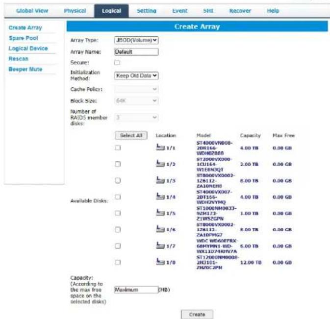
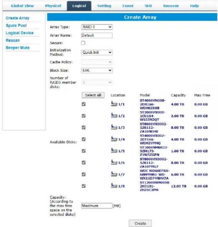
- The RAID creation page provides many features, options, and settings.
-
Select RAID 0 for Array Type.
-
If desired name the array. The example shown below uses the name "Default".
- Select Quick Init as the initialization method.
Note: Quick Init gives immediate access to the array by skipping parity synchronization. Recommended for testing/verification purposes or when new disks are used.
- Select 64K as the Block Size.
- Select all 8 available disks.
- Leave the Capacity setting at their default values.
- Click Create.
- Once created, the WebGUI will acknowledge the array has been create.
localhost:7402 says
RAID 0 Array 'RAID_0_0' has been created successfully (Disk 1:ST4000VN008-2DR166-WDH0Z888, 1/1; Disk 2:ST2000VX000-1CU164-W1E8N3QT, 1/2; Disk 3:ST8000VX0002-1Z6112-ZA10NEH8, 1/3; Disk 4:ST4000VX007-2DT166-WDH2VYMQ, 1/4; Disk 5:ST1000NM0033-9ZM173-Z1W5ZGPN, 1/5; Disk 6:ST8000VX0002-1Z6112-ZA10PMG7, 1/6; Disk 7:WDC WD60EFRX-68MYMN1-WD-WX11D74RHV7A, 1/7; Disk 8:ST12000NM0008-2H3101-ZHZ0C2PM, 1/8).

- RAID_0_0 can now be seen under Logical Device Information.
Note: The OS name is HPT DISK 0_0; this will help identify which volume to initialize.
Step 5B: Create RAID Arrays using CLI
For Windows and Linux Users
- Open "Terminal" and enter root permissions.
- Then execute the command "hptraidconf" to enter the CLI.
- In order to see the devices connected to the Enclosure, type query devices.
| HPT CLI > query devices | ||||||
| ID | Secured | Capacity | MaxFree | Flag | Status | ModelNumber |
| 1/1 | No | 4000.79 | 0 | SINGLE | LEGACY | ST4000VN008-2DR166 |
| 1/2 | No | 2000.40 | 0 | SINGLE | LEGACY | ST2000VX000-1CU164 |
| 1/3 | No | 8001.56 | 0 | SINGLE | LEGACY | ST8000VX0002-1Z6112 |
| 1/4 | No | 4000.79 | 0 | SINGLE | LEGACY | ST4000VX007-2DT166 |
| 1/5 | No | 1000.20 | 0 | SINGLE | LEGACY | ST1000NM0033-9ZM173 |
| 1/6 | No | 8001.56 | 0 | SINGLE | LEGACY | ST8000VX0002-1Z6112 |
| 1/7 | No | 6001.18 | 0 | SINGLE | LEGACY | WDC WD60EFRX-68MYMN1 |
| 1/8 | No | 12000.14 | 0 | SINGLE | LEGACY | ST12000NM0008-2H3101 |
Note: The device ID gives the position of each drive and is needed to select which drive will be included in the array.
- If you selected the legacy disk for RAID array creation, you need to initialize the legacy disk first. Using the following command to initialize legacy disks:
HPT CLI > init deviceid start

After init initialize legacy disks:
| HPT CLI > query devices | ||||||
| ID | Secured | Capacity | MaxFree | Flag | Status | ModelNumber |
| 1/1 | No | 4000.69 | 4000.69 | SINGLE | NORMAL | ST4000VN008-2DR166 |
| 1/2 | No | 2000.31 | 2000.31 | SINGLE | NORMAL | ST2000VX000-1CU164 |
| 1/3 | No | 8001.46 | 8001.46 | SINGLE | NORMAL | ST8000VX0002-1Z6112 |
| 1/4 | No | 4000.69 | 4000.69 | SINGLE | NORMAL | ST4000VX007-2DT166 |
| 1/5 | No | 1000.12 | 1000.12 | SINGLE | NORMAL | ST1000NM0033-9ZM173 |
| 1/6 | No | 8001.46 | 8001.46 | SINGLE | NORMAL | ST8000VX0002-1Z6112 |
| 1/7 | No | 6001.08 | 6001.08 | SINGLE | NORMAL | WDC WD60EFRX-68MYMN1 |
| 1/8 | No | 12000.07 | 12000.07 | SINGLE | NORMAL | ST12000NM0008-2H3101 |
- To create a 8 disk RAID 0 array named RAID0 input the following command:
HPT CLI > create RAID0 name=RAID0 disks=*

- To view the created array, type query arrays.
| HPT CLI > query arrays | ||||||||
| ID | Secured | Capacity(GB) | Type | Status | Block | Sector | Cache | Name |
| 1 | No | 8000.99 | RAID0 | NORMAL | 64k | 512B | NONE | RAID0 |
Note: For more HighPoint CLI information type help in the command line or refer to the documentation included in the software package.
Step 6: Initialize and format the RAID Array
Before using the newly created RAID array, you must initialize and format the new volume.
For Windows Users
- After creating the RAID array, open Windows Disk Management.
- Disk Management will ask to initialize unknown disks either in MBR format or GPT.
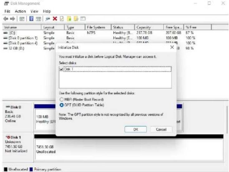
Note: As a general rule, select MBR for disks less than 2TB and GPT for disks greater than 2TB.
- Right click the new disk, and click properties.
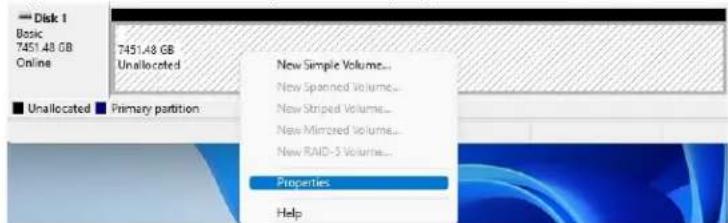
- In properties, check and make sure it is an HPT Disk.
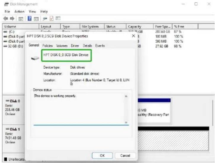
- Once the disk has been confirmed, right click the unallocated space and click NewSimple Volume.
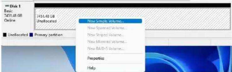
- Follow the on-screen instructions to configure and format the drive.
- Once finished, the new volume will receive a drive letter and be available for use.

For Mac Users
- After creating a RAID array, click Initialize when prompted. (Note: If you ignored the prompt, simply open Disk Utility).
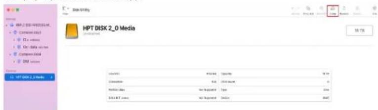
- In Disk Utility, select the Volume you created on the right, then click the Erase tab.

Erase "HPT DISK 2\_0 Media"?
Erasing "HPT DISK 2_0 Media" will permanently erase all data stored on it. You can't undo this action.
Name: Tutorial_array
Format: Mac OS Extended (Journaled)
Scheme: GUID Partition Map


Security Options...
Cancel
Erase
- Select the desired disk format and disk name then click Erase. (Note: All previousdata on disks will be erased.)

Erasing "HPT DISK 2\_0 Media" and creating "Tutorial\_array"
Erase process is complete. Click Done to continue.
Hide Details
unfounding data
Creating the partition map
Waiting for partitions to activate
Formatting disk5s2 as Mac OS Extended (Journaled) with name Tutorial_array Initialized /dev/rdisk5s2 as a 16 TB case-insensitive HFS Plus volume with a 524288k journal
Mounting disk
Operation successful.
Done
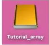
- When finished, your new RAID volume will be available for use.
For Linux Users
- Enter the terminal with root privileges.
- Enter the command "Isblk", lists information for all available block devices.
root@t-desktop:/home/t/Desktop# lsblk
NAME MAJ:MIN RM SIZE RO TYPE MOUNTPOINT
loop0 7:0 0 4K 1 loop /snap/bare/5
loop1 7:1 0 63.3M 1 loop /snap/core20/1828
loop2 7:2 0 91.7M 1 loop /snap/gtk-common-themes/1535
loop3 7:3 0 40.9M 1 loop /snap/snapd/20290
loop4 7:4 0 346.3M 1 loop /snap/gnome-3-38-2004/119
loop5 7:5 0 46M 1 loop /snap/snap-store/638
loop6 7:6 0 49.9M 1 loop /snap/snapd/18357
loop7 7:7 0 349.7M 1 loop /snap/gnome-3-38-2004/143
sda 8:0 0 7.3T 0 disk
- Enter the command to format the RAID "mkfs.ext4 /dev/sda".
root@t-desktop:/home/t/Desktop# mkfs.ext4 /dev/sda
mke2fs 1.45.5 (07-Jan-2020)
Creating filesystem with 1953366016 4k blocks and 244170752 inodes
Filesystem UUID: 75f2a797-1465-4df6-b555-02ca96030b2e
Superblock backups stored on blocks:
32768, 98304, 163840, 229376, 294912, 819200, 884736, 1605632, 2654208,
4096000, 7962624, 11239424, 20480000, 23887872, 71063616, 78675908,
102400000, 214990848, 512000000, 550731776, 644972544, 1934917632

Allocating group tables: done
Writing inode tables: done
Creating journal (262144 blocks): done
Writing superblocks and filesystem accounting information: done
- Mount the partition to /mnt "mount /dev/sda /mnt".
root@t-desktop:/home/t/Desktop# mount /dev/sda /mnt
- When finished, your new RAID volume will be available for use.
Step 7: Manage your RAID array
The following features allow you to monitor and maintain your arrays to prevent any critical failures from occurring:
- Spare Pool
- Email Notifications
- WebGUI Remote Login
● Storage Health Inspector
RAID Spare Pool
Physical drives marked as a spare will automatically be added to a redundant RAID array (RAID levels 1, 10, 5, 50 and 6) whenever there is a disk failure. Enabling this feature minimizes the chances of data loss since it reduces the time an array is in critical status.
Add/Remove Spare Using WebGUI
- Log in WebGUI.
- Click Logical.
- Click Spare Pool.
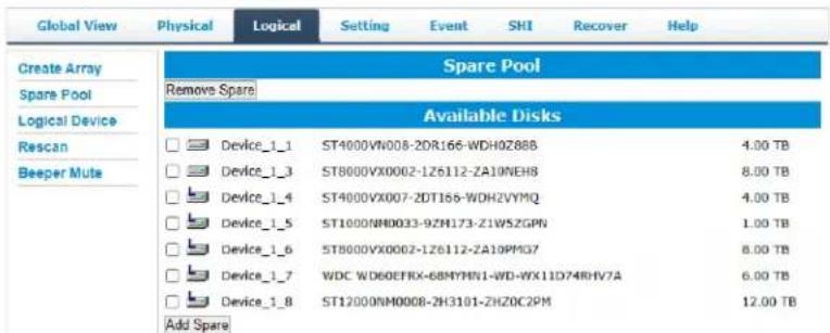
- Check the box for the disk you want as a spare from Available Disks.
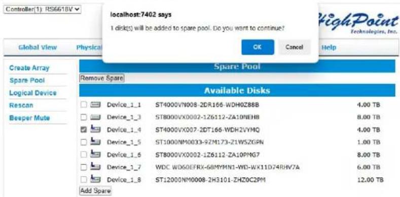
- Click Add Spare. Then click OK
- Disks that have been added to the Spare Pool are displayed in the Spare Pool.
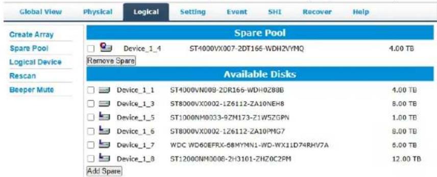
Note: Disks added to the spare pool will show under Spare Pool and can be removed by checking the disk checkbox from Spare Pool > Click Remove Spare.
Email Notifications
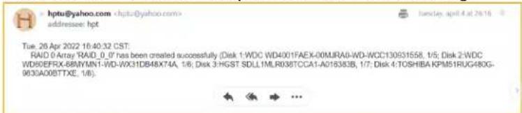
When enabled, all added recipients will receive an email notification for any event log entries.
The following topics are covered under email:
- SMTP Setting
- Adding Recipients
SMTP settings
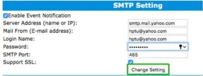
Note: After you click Change Setting, the password field will be reset.
To set up email alerts:
Using a Yahoo Mail account as an example:
- Check the Enable Event Notification box.
- Enter the ISP server address name or SMTP name.
For example: smtp.mail.yahoo.com
- Type in the email address of the sender. (email account that is going to send the alert)
For example: hptu@yahoo.com
- Type in the account name and password of the sender.
- Type in the SMTP port. (default: 25)
- Check the support SSL box if SSL is supported by your ISP (note the port value will change to 465).
Email Precautions
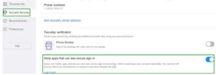
If you want to receive notification mail using a Webmail account, you may need to modify the mailbox's permissions. The following example is for a Yahoo and outlook webmail account.
Yahoo Setting:
To change permission settings, please refer to the following link:
https://help.yahoo.com/kb/account/SLN27791.html?impressions=true
- Log in to yahoo email; click "Sign in" to log in: https://www.yahoo.com

- After a successful login, click "Account Info" under the user name.

-
Go to the "Account Info" page, click "Account Security".
-
On the "Account Security" page, click the "Allow apps that use less secure sign in" button.
Outlook Setting:
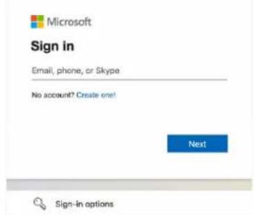
- Sign in to mail and set it up, Login email address link: https://outlook.live.com/mail/inbox
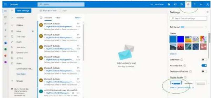
- Click Settings in the upper right corner, select the lower left corner: View all outlook settings
- Enter the redirect page, select mail, then click Sync email.
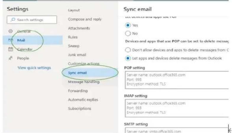
- Let devices and apps use pop select "yes".
- Choose 'Let app and devices delete messages from Outlook'
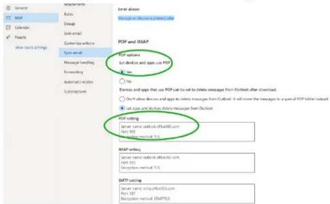
Notes:
The screenshot below can be used as a reference. The POP setting is the mailbox server.
If you are having trouble configuring notification for your Email account, please contact our Technical Support Department
Adding Email Recipients
You can add multiple email addresses as receivers of a notice.
- Type the email of the recipient in the E-mail text box.
- Type the name of the recipient in the Name text box.
- Set which type(s) of events will trigger an email using the respective Event Level check boxes.
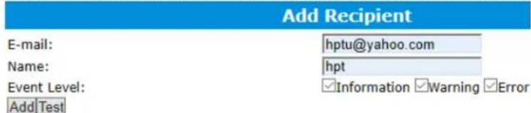
- (Optional) Click test to confirm the settings are correct by sending out a test email.
Mail has been sent successfully.
Close
- Click add to add the "recipient to recipient" list.
- The added recipient will display in under Recipients.
| Recipients | ||
| Name | Event Level | |
| hptu@yahoo.com Delete | hpt | Information, Warning, Error |
- The email will include the output recorded in the event log.
WebGUI Remote Login
A user connected to a local network can remotely access the WebGUI using the IPAddress of the host device.
To obtain your IP address
Note: If you want to use this function, please set WEBGUI login password to prevent others from changing your settings
For Windows Users
- Open a command prompt window on the host computer.
- Type ipconfig.
- Look for the section that contains your network adapter information.
- Note the IP address.
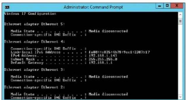
Figure. Example: The IPv4 address is under Ethernet adapter Ethernet 4 and is 192.168.1.143
Note: Make sure Restrict to localhost access is disabled in WebGUI Setting (Refer to setting)
- You can then remotely access the WebGUI using any other computer that is in your local network by opening any web browser and typing http://{IP address of host computer}:7402 (default port is 7402).
For Mac Users
- Open a terminal window on the host computer. (Computer that is connected to the devices.)
- Type ifconfig.
- Look for the connection that has status: active.
- Write the IP address located after inet:
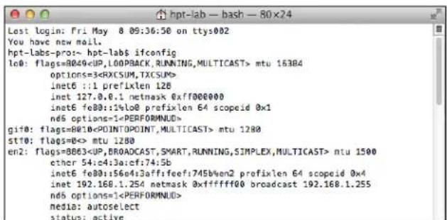
Figure. Example: en2 has active status, the IP is 192.168.1.254
- You can then remotely access the WebGUI using any other computer that is in your local network by opening any web browser and typing http://{IP address of host computer}:7402 (default port is 7402).
For Linux Users
- Open a terminal window on the host computer
- Type "ip addr".
- Look for the section that contains your network adapter information.
- Note the IP address.
root@test-System-Product-name:/home/test/Desktop# lp addr
1: lo: <LOOPBACK,UP,LOWER_UP> mtu 65536 qdisc noqueue state UNKNOWN group default qlen 1000
    link/loopback 00:00:06:00:08:00 brd 08:00:00:08:00:00
    inet 127.0.6.1/8 scope host lo
    valid_lft forever preferred_lft forever
    inet6 ::1/128 scope host
    valid_lft forever preferred_lft forever
2: enp5s0: <BROADCAST,MULTICAST,UP,LOWER_UP> mtu 1500 qdisc mq state UP group default qlen 1000
    link/ether 58:eb:f6:77:07:f2 brd ff:ff:ff:ff:ff:ff
    inet 192.168.0.184/24 brd 192.168.0.255 scope global dynamic noprefixroute enp5s0
    valid_lft 86322sec preferred_lft 86322sec
    inet6 fe8b:bc8c:fdbb:6325:49a1/64 scope link noprefixroute
    valid_lft forever preferred_lft forever
3: wlp3s0: <NO-CARRIER,BROADCAST,MULTICAST,UP> mtu 1500 qdisc noqueue state DOWN group default qlen 1000
    link/ether 1c:c1:0c:18:4e:3f brd ff:ff:ff:ff:ff:ff
Example: enp5s0 has active status, the IP is 192.168.0.184
Note: Make sure Restrict to localhost access is disabled in WebGUI Setting (Refer to setting)
- You can then remotely access the WebGUI using any other computer that is in your local network by opening any web browser and typing http://{IP address of host computer}:7402 (default port is 7402).
Storage Health Inspection (SHI)
The Storage Health Inspector (SHI) monitors each individual disk's health. Monitoringdisk SMART attributes can prevent critical RAID failures from occurring.
This section covers the following:
● Enabling SMART Monitoring
● Disabling SMART Monitoring
● Storage Health Inspector Scheduling
Enabling SMART Monitoring
| Global View | Physical | Logical | Setting | Event | SHI | Recover | Help |
Schedule
| Storage Health Inspector(SHI) | ||||||
| Controller ID | Location# | Device Serial Number | RAID | °F | Bad Sectors Found & Repaired | S.M.A.R.T |
| 1 | 1 | WDH0Z88B | RAID_5_0 | 80 | None | Detail |
| 1 | 2 | W1E8N3QT | RAID_5_0 | 89 | 16 | Detail |
| 1 | 3 | ZA10NEH8 | RAID_5_0 | 100 | None | Detail |
| 1 | 4 | WDH2VYMQ | None | 86 | 8 | Detail |
| 1 | 5 | Z1W5ZGPN | None | 96 | None | Detail |
| 1 | 6 | ZA10PMG7 | None | 104 | None | Detail |
| 1 | 7 | WD-WX11D74RHV7A | None | 95 | None | Detail |
| 1 | 8 | ZHZ0C2PM | None | 91 | None | Detail |
Device Name Device_1_1
Model Number ST4000VN008-2DR166-WDH0Z88B
S.M.A.R.T Enabled Disable
S.M.A.R.T Attributes
| ID | Name | Threshold | Worst | Value | Status |
| 1 | Raw Read Error Rate | 44 | 64 | 83 | OK |
| 3 | Spin Up Time | 0 | 91 | 93 | OK |
| 4 | Start Stop Count | 20 | 95 | 95 | OK |
| 5 | Reallocated Sector Ct | 10 | 100 | 100 | OK |
| 7 | Seek Error Rate | 45 | 60 | 85 | OK |
| 9 | Power On Hours | 0 | 93 | 93 | OK |
| a | Spin Retry Count | 97 | 100 | 100 | OK |
| c | Power Cycle Count | 20 | 96 | 96 | OK |
| b8 | Unknown Attribute | 99 | 100 | 100 | OK |
| bb | Unknown Attribute | 0 | 100 | 100 | OK |
| bc | Unknown Attribute | 0 | 96 | 100 | OK |
| bd | Unknown Attribute | 0 | 100 | 100 | OK |
| be | Unknown Attribute | 40 | 40 | 73 | OK |
| bf | G-Sense Error Rate | 0 | 100 | 100 | OK |
| c0 | Power-Off Retract Count | 0 | 99 | 99 | OK |
| c1 | Emergency Retract Cycle Ct | 0 | 92 | 92 | OK |
| c5 | Current Pending Sector | 0 | 100 | 100 | OK |
| c6 | Offline Uncorrectable | 0 | 100 | 100 | OK |
| c7 | UDMA CRC Error Count | 0 | 188 | 200 | OK |
| f0 | Head Flying Hours | 0 | 253 | 100 | OK |
| f1 | Unknown Attribute | 0 | 253 | 100 | OK |
| f2 | Unknown Attribute | 0 | 253 | 100 | OK |
HDD Temperature Threshold
Set harddisk temperature threshold : 140 °F Set
To access the SMART attributes of an individual disk:
- Log in to WebGUI.
- Select the proper controller using the drop down menu on the top left.
- Click the SHI tab.
- Click Detail on the desired disk.
- Click Enable to enable SMART monitoring.
Disabling SMART monitoring
| Global View Physical Logical Setting Event SHI Recover Help | ||||||
| Schedule | ||||||
| Storage Health Inspector(SHI) | ||||||
| Controller ID | Location# | Device Serial Number | RAID | #F | Bad Sectors Found & Repaired | S.M.A.R.T |
| 1 | 1 | WDH0Z8BB | RAID_5_0 | N/A | None | Detail |
| 1 | 2 | WIEBN3QT | RAID_5_0 | 89 | 16 | Detail |
| 1 | 3 | ZA10NEHB | RAID_5_0 | 100 | None | Detail |
| 1 | 4 | WDH2VYMQ | None | 80 | 8 | Detail |
| 1 | 5 | Z1WSZGPN | None | 96 | None | Detail |
| 1 | 6 | ZA10PMG7 | None | 104 | None | Detail |
| 1 | 7 | WD-WX11D74RHV7A | None | 95 | None | Detail |
| 1 | 8 | ZHZOCZPM | None | 91 | None | Detail |
| HDD Temperature Threshold | |
| Set harddisk temperature threshold : 140 °F Set |
HighPoint RAID Management 3.0.15
Copyright (c) 2023 HighPoint Technologies, Inc. All Rights Reserved
You have the option to disable SMART monitoring on each individual disk:
- Select the proper controller using the drop down menu on the top left.
- Click the SHI tab.
- Click SMART on desired disk.
- Click Disabled.
Note: Disabling SMART will prompt the Storage Health Inspector to change the diskstatus to 'Failed'. The Enclosure alarm will not alert you when this setting is disabled. Any potential warnings related to S.M.A.R.T attribute technology will not trigger.
Storage Health Inspector Scheduling
The Scheduler enables you to schedule disk/array checkups to ensure disks/array are functioning optimally.
RAID1/10/50/6 will appear under New Verify Task: Log into the HRM.
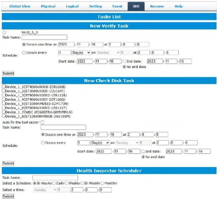
- Select the proper controller from the top left drop down.
- Click SHI.
- Click Schedule a task.
- Select the array you want to schedule the verify task.
- Type the name in Task Name entry box.
- Choose whether you want to schedule.
- One time verify task on specific date (YYYY-MM-DD) at (HH:MM:SS, 24-hr clock).
- Or a specific schedule you can adjust based on Daily, Weekly, or Monthly options.
9. Click Submit.
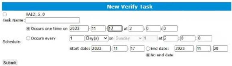
10. Your entry will appear under Tasks List.

Note: New Verify Task box only appears if you have normal status arrays. If you have acritical array, New Rebuild Task will replace New Verify Task.
RAID Expansion (OCE/ORLM)
Important: Before using OCE/ORLM, we recommend that you Verify the current RAID array, using the WebGUI's Verify function, under Maintenance. The OCE/ORLM process is irreversible; once you start an OCE/ORLM procedure, the process can be temporarily paused (using the Maintenance option), but it must ultimately be resumed until completion.
OCE – Online Capacity Expansion
OCE allows you to add storage capacity to an existing RAID array while preserving your existing data. In most cases, this feature is used when adding one or more physical drives to an array (for example, expanding from a 3-drive RAID 5 configuration to a 7-drive RAID 5 configuration).
ORLM – Online RAID Level Migration
ORLM allows you to convert RAID levels for an existing RAID while preserving existing data. In most cases, this feature is used to convert one RAID level to another. (for example, converting from RAID 1 to RAID 10).
Take ORLM for example.
- Start the WebGUI and click the Logical tab.
- Locate the array you want to expand, and click the Maintenance option displayed to the far-right of the interface.

- Under the "JBOD/Volume" drop-down menu, make sure you select the array's current RAID level. In this example, the target array is a RAID 5 configuration:
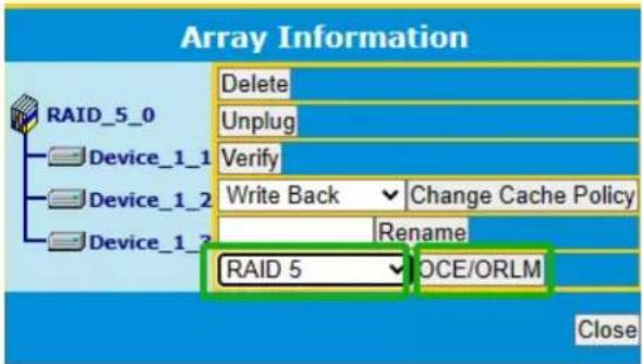
- Click the "OCE/ORLM" button continue. The WebGUI will display the following warning message. Click OK if you wish to proceed.
localhost:7402 says
Please make sure all member disks of this array are healthy before doing this operation since it is irreversible(You can run "Check Disk" on the "Physical" page.),do you want to continue?

- This will open the "Array transform/transforming" menu.
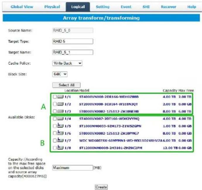
- First, check the box before the top entry (A) – this is the current array.
- Next, check the box for each additional drive you want to add to the array (B)
- Click "Create". The WebGUI will announce that your new configuration was created successfully. Click OK to continue.
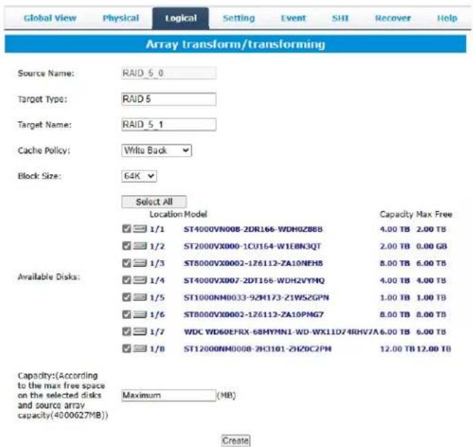
- The Status will change to "Expanding/Migrating" and will display a progress bar.
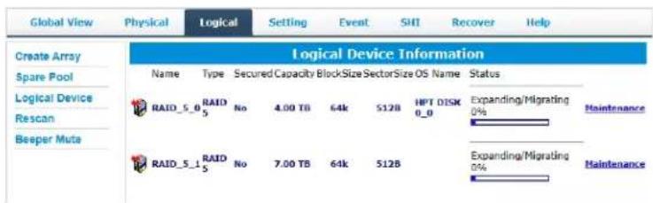
- Once complete, your operating system will recognize the additional capacity as unpartitioned space – you are free to partition/format this space as a separate volume, or expand the current partition to include this space.
Troubleshooting – Hardware
If you face any hardware related issues involving the RS6614V/RS6618V Enclosure OR disk drives, refer to the following sections for troubleshooting tips. For all other problems, submit a support.
Enclosure Mute Button
The mute button on the back will mute the alarm for enclosure related issues such as enclosure FAN or TEMPERATURE failures.
LED Activity
The following information tells you how to interpret LED activity seen on the enclosure and disk trays.
Table 1. LED Status Information
| LED Type | Interpretation |
| Power LED | SOLID BLUE (Normal Status) |
| Warning LED | FLASH YELLOW. The enclosure's temperature has exceeded the warning threshold 55°C or the fan speed is below normal operating levels 700rpm/min |
| Fail LED | SOLID RED. The temperature is greater than 60°C;FLASH RED. The fan speed is less than 500 rpm/min, the red light is flashing, and generates an audible alarm |
| UNLIT | Unit is powered OFFDisk tray is empty |
Table 2. LED Diagrams
| LED Location | Icon | Normal |
| Disk Tray Top LED | 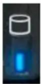 | • SOLD BLUE: the disk tray is occupied, but the disk is not in use |
| Disk Tray Bottom LED | 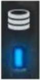 | FLASHING BLUE: the disk is in use (read/write I/O) |
| Power LED |  | SOLID BLUE: the enclosure is powered onUNLIT: the enclosure is not connected to an active host system |
| Fail LED |  | SOLID RED. The temperature is greater than 60°C;FLASH RED. The fan speed is less than 500 rpm/min, the red light is flashing, and generates an audible alarm |
| Warning LED |  | FLASH YELLOW. The enclosure's temperature has exceeded the warning threshold 55°C or the fan speed is below normal operating levels 700rpm/min |
Replacing a Failed Disk
When a disk in your array fails it is important to get it replaced or rebuilt as soon as possible to prevent any data loss.
-
Identify the faulty disk.
-
Look at the front panel for the RED disk error LED to be LIT.
-
Log in to WebGUI and check the Logical Tab.
-
Once disk has been identified press the disk tray blue tab and slide the failed driveout.
-
Replace the failed drive with a new drive.
- If auto rebuild is enabled, the rebuild process should start immediately.
- If auto rebuild is disabled, click rescan on the left panel to initiate rebuilding.
Troubleshooting - Software
If you have problems in use, please submit the log to our online service (https://www.highpoint-tech.com/support-and-services).
Troubleshooting – RAID
If you face any RAID related issues involving your RAID array, refer to the following sections for troubleshooting tips. For all other problems, submit a support ticket at https://www.highpoint-tech.com/support-and-services
Critical Arrays
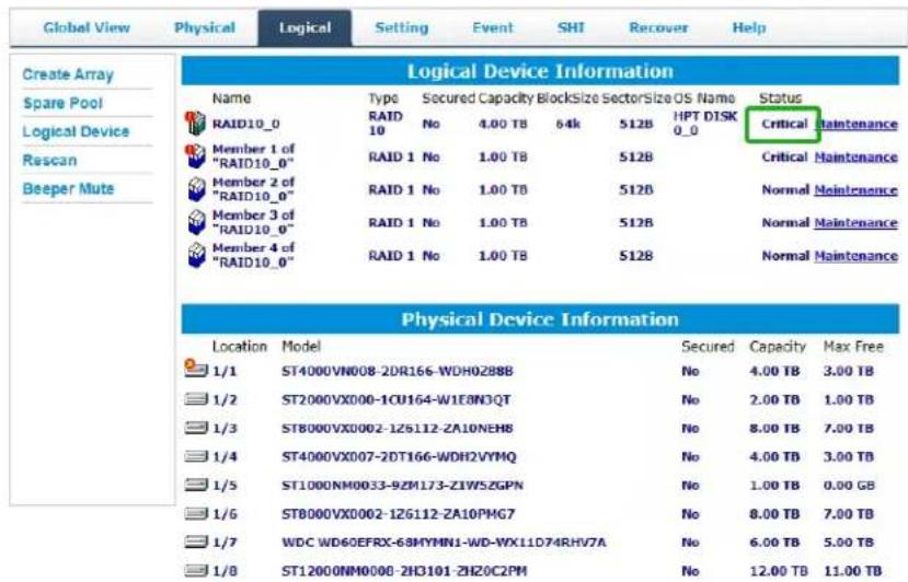
When your disk is critical, that means your array as a whole is still accessible, but adisk or two is faulty (depending on your RAID level) is in danger of failing.
Common scenarios for criticalarray status
• Unplugging disk that is part of an array
• Bad sector detected on a disk part of thearray
• Unrecoverable data during rebuilding
• Defective port or cable interrupts rebuilding process
To recover from this situation,
- Backup your existing data.
- Identify which disk is faulty.
• Refer to the WebGUI Logical tab and Event tab.
- Replace with a new disk, and the "faulty" disk can be checked later.
• If Auto-Rebuild is enabled:
Replace the faulty disk. The WebGUI should initiate a rebuild immediately after the replacement disk is detected. If the disk is not detected, or the Rebuild procedure does not start, click Rescan. Once a new disk is added, add the new disk into the critical array.
• If Auto-Rebuild is disabled:
Replace the faulty disk.
Log in to the WebGUI.
Click the Logical Tab.
Click Maintenance > Add disk > and select the appropriate disk.
The Rebuild process should now begin.
If the rebuild process does not start, click Rescan.
Note: Rebuilding an array takes on average 2 hours per 1 Terabyte of disk capacity. The process will scan through the entire disk, even if you have very little used disk space.
Rebuild failed
If rebuilding fails to complete due to bad disk sector errors (check in the Event Log), the WebGUI provides an option called "Continue Rebuilding on Error".
- Log in to WebGUI.
- Click Setting tab.
- Under System Setting, change Enable Continue Rebuilding on Error to Enabled.
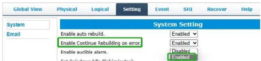
This option will enable Rebuild process to ignore bad sectors and attempt to make your dataaccessible. It is important to backup immediately after to rebuild is complete and replaceor repair any disk(s) with bad sectors.
Critical array becomes disabled when faulty disk was removed
If this is the case, check to make sure you removed the correct disk. When you removethe wrong disk from a critical array, the array status may become disabled. Data is inaccessible for disabled arrays. Follow these steps to restore the previous state:
- Shut down your PC and the RS6614V/RS6618V Enclosure.
- Place all disks, including the removed disks, back to original array configuration.
- Boot up PC.
- Once array is back to critical status, identify the correct disk (using the event log) and replace it.
Disabled Arrays
| Global View Physical Logical Device Information | |||||||
| Name | Type | Secured Capacity BlockSize Sector Size OS Name Status | |||||
| RAID10_0 | RAID 10 No | 4.00 TB | 64k | 512B | Disabled Maintenance | ||
| Member 1 of "RAID10_0" | RAID 1 No | 1.00 TB | 512B | Disabled Maintenance | |||
| Member 2 of "RAID10_0" | RAID 1 No | 1.00 TB | 512B | Normal Maintenance | |||
| Member 3 of "RAID10_0" | RAID 1 No | 1.00 TB | 512B | Normal Maintenance | |||
| Member 4 of "RAID10_0" | RAID 1 No | 1.00 TB | 512B | Normal Maintenance | |||
| Location Model | Secured Capacity Max Free | ||||||
| 1/1 ST4000VN008-2DR166-WDH0Z88B | No 4.00 TB 3.00 TB | ||||||
| 1/2 ST2000VX000-1CU164-W1E8N3QT | No 2.00 TB 1.00 TB | ||||||
| 1/3 ST8000VX0002-126112-ZA10NEH8 | No 8.00 TB 7.00 TB | ||||||
| 1/4 ST4000VX007-2DT166-WDHZVYMQ | No 4.00 TB 3.00 TB | ||||||
| 1/5 ST1000NM0033-9ZM173-ZIWSZGPN | No 1.00 TB 0.00 GB | ||||||
| 1/6 ST8000VX0002-126112-ZA10PMG7 | No 8.00 TB 7.00 TB | ||||||
| 1/7 WDC WD6OEFRX-68MYMN1-WD-WX11D74RHV7A | No 6.00 TB 5.00 TB | ||||||
| 1/8 ST12000NM0008-2H3101-ZHZOC2PM | No 12.00 TB 11.99 TB | ||||||
If two or more disks in your array go offline due to an error or physical disconnection your array will become disabled.
To recover a disabled array, using the 'Recover Tab' will yield the best results. To utilize the Recover tab, you will need to insert the exact physical drives that are listed on the recover list. The goal of using recover is to get the RAID status back to critical/normal, allowing you to access and back up your data.
Recover with RAID Maintenance
- Log in to WebGUI.
- Click Maintenance for the array that is disabled.
- Click Recover.
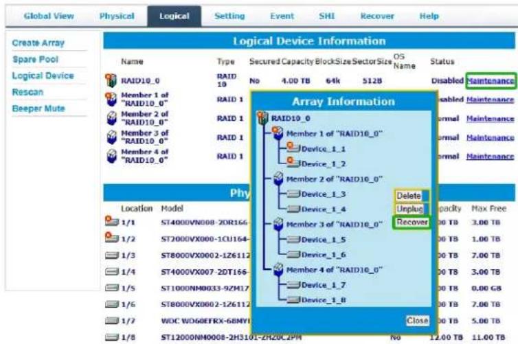
Recover RAID with Recover Tab
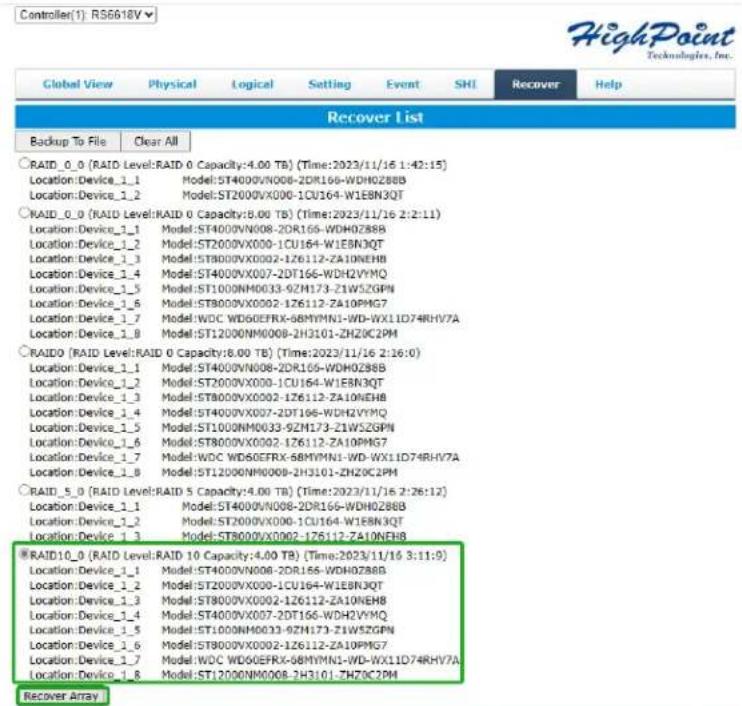
Before using the Recover tab to recover your array, check to see if the RAID array is listed in your Recover List. Once you have confirmed the RAID array is there, proceed to delete the disabled array.
- Log in to WebGUI.
- Click Maintenance for the array that is disabled.
- Click Delete, to delete the disabled array.
- Click Recover Tab.
-
Select the RAID configuration you just deleted.
-
Click Recover Array.
Online Array Roaming
One of the features of all HighPoint RAID Enclosure is online array roaming. Information about the RAID configuration is stored on the physical drives. So, if the RS6614V/RS6618V fails or you wish to use another RAID Enclosure or RAID controller, or you wish the drives to be moved to a different Enclosure or controller, the RAID configuration data can still be read by another HighPoint RAID Enclosure or RAID controller.
Note: The prerequisite for using this feature is that both RAID Enclosures or RAID controllers are using the same type of driver.
Appendix A: Navigating the HighPoint WebGUI
| Tab Name | Function |
| Global View | View HBA and Storage Properties |
| Physical | View Additional Controller propertiesView disk propertiesAdjust selected disk behaviors |
| Logical | Manage and create RAID arrays |
| Setting | Adjust WebGUI controls settings |
| Event | Show WebGUI Event Log |
| SHI (Storage Health Inspector) | View and schedule S.M.A.R.T monitoring |
| Recover | Revert to previously created arrays |
| Logout | Logout of WebGUI, set password will appear |
| Help | Online HelpDiagnostic- collect log information |
Appendix A-1: Global View Tab
Take RocketStor 6618V as an example.
Controller(1): RS6618V
HighPoint Technologies, Inc.
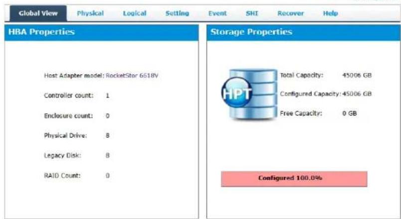
The WebGUI Global view provides an overview of what each Enclosure connected to your computer detects. It is also the first page you see when logging in.
● Host Bus Adapter Properties
● Storage Properties
On the top left of the page is a drop-down menu that allows you to select which controller you want to manage (if you have multiple HighPoint products connected).
HBA Properties
● Host Adapter model: the model name of the Enclosure
● Controller Count: number of Enclosure detected
● Enclosure Count: number of external enclosures detected
● Physical drives: number of drives seen by the controller
● Legacy Disks: number of Legacy disks connected. Legacy disks are physical drivesthat have previous partitions stored on them
● RAID Count: number of RAID arrays
Storage Properties
● Total capacity: the combined capacity of each physical disk connected to the Enclosure
- Configured capacity: the amount of space used for creating arrays
● Free Capacity: total amount of space unused
Appendix A-2: Physical Tab
| Global View | Physical | Logical | Setting | Event | SII | Recover | Help |
| Controller 1 | Controller Information | ||||||
| Devices | Model Name: | RocketStor 6618V | |||||
| Vendor: | HighPoint Technologies, Inc. | ||||||
| Spinup | Vendor ID: | 0x1103 | |||||
| Device ID: | 0x3720 | ||||||
| Sub Vendor ID: | 0x1103 | ||||||
| Rescan | Sub Device ID: | 0x6618 | |||||
| PCI Bus Number: | 50 | ||||||
| PCI Device Number: | 0 | ||||||
| PCI Func Number: | 0 | ||||||
| Maximum Link Width: | x8 | ||||||
| Current Link Width: | x8 | ||||||
| Maximum Link Speed: | 8.0 GT/s | ||||||
| Current Link Speed: | 8.0 GT/s | ||||||
| BIOS Version: | v1.0.1 | ||||||
| PCB Version: | v1.2 | ||||||
| MCU Version: | v1.1.2 | ||||||
The physical tab shows general and extended information about the Enclosure you are using. Information about the MCU, BIOS, and PCB are all located here. This information is useful for identifying what Enclosure model you have and to make sure you have the most updated version available.
The physical tab contains the following information:
● Controller Information
● Physical Devices Information
Controller Information
| Global View | Physical | Logical | Setting | Event | SHI | Recover | Help |
| Controller 1 | Controller Information | ||||||
| Devices | Model Name: | RocketStor 6618V | |||||
| Vendor: | HighPoint Technologies, Inc. | ||||||
| Spinup | Vendor ID: | 0x1103 | |||||
| Device ID: | 0x3720 | ||||||
| Sub Vendor ID: | 0x1103 | ||||||
| Sub Device ID: | 0x6618 | ||||||
| Rescan | PCI Bus Number: | 60 | |||||
| PCI Device Number: | 0 | ||||||
| PCI Func Number: | 0 | ||||||
| Maximum Link Width: | x8 | ||||||
| Current Link Width: | x8 | ||||||
| Maximum Link Speed: | 8.0 GT/s | ||||||
| Current Link Speed: | 8.0 GT/s | ||||||
| BIOS Version: | v1.0.1 | ||||||
| PCB Version: | v1.2 | ||||||
| MCU Version: | v1.1.2 | ||||||
● Model Name: model name of the device connected
● Vendor: the controller's owner
● Current Link Width: PCIe width occupied by the current controller
● Current Link Speed: Rate of current bandwidth
● BIOS Version: BIOS version of the controller
● PCB Version: PCB version of the controller
● MCU Version: MCU version of the controller
Physical Devices Information
The following properties are part of the Physical Devices Information box under the Physical tab.
![Global View Physical Logical Setting Event SHI Recover Help Controller 1 Devices Spinup Rescan Physical Devices Information Dump Array Info Device 1.1 Model ST4000VN008-2DR166- WDH0Z88B Capacity 4.00 TB Unolus Revision SC50 Read Ahead Enabled Change Location 1/1 Write Cache Enabled Change Max Free 0.00 GB Status Legacy NCQ Enabled Change Serial Num WDH0Z88B Identify LED [ON] [OFF] Interface SATA Type HDD SED Capable No SED Type None Secured No Cryptographic Er ase Capable No Check Disk Start Fix Bad Sector](/content/2026/05/958467/images/557bf36d9f1d00cd0b0915b7ff4a2af7cf2cdec4360f1a170ea8e41139adcd86.jpg)
● Model – Model number of the physical drive
● Capacity – Total capacity of the physical drive
Revision – HDD device firmware revision number
- Read Ahead* - (Enable/Disable) Disk read ahead.
- Location – Device location (example: 1/2 states controller 1, slot 2)
- Write Cache* – (Enable/Disable) the disk write cache
● Max Free – space on disk that is not configured in an array
● Status – (Normal, disabled, critical) status of the disk
- NCQ* – (Enable/Disable) Native Command Queuing
- Serial Number – serial number of the physical disk
- Identify LED* – On/Off – toggle the IDENTIFY (RED) on the front panel
- Check Disk ^1 - Fix Bad Sector
- Interface ^1 – interface of the physical disk
- Type ^1 – Type of the physical disk
- Unplug ^1 – Safely ejects selected disk. Other methods of disk removal will triggeralarm if enabled.
Notes :
* Disk properties that can be adjusted.
^1 This information is only displayed in the Windows HighPoint RAID Management Software.
Read Ahead
Enabling disk read ahead will speed up read operations by pre-fetching data and loading it into RAM.
Write Cache
Enabling write cache will speed up write operations.
NCQ (Native Command Queuing)
A setting that allows disks to queue up and reorder I/O commands for maximum efficiency.
Identify LED
The Disk tray LED lights on the front panel can be toggled ON or OFF.
Rescan
Clicking rescan will immediately signal the controller to scan for any changes in the connection. Clicking this button will also stop any alarm if currently ringing.
Appendix A-3: Logical Tab
| Global View | Physical | Logical | Setting | Event | SHI | Recover | Help |
| Create Array | |||||||
| Spare Pool | |||||||
| Logical Device | |||||||
| Ruscan | |||||||
| Beeper Mute | |||||||
| Logical Device Information | |||||||
Physical Device Information
| Location | Model | Secured | Capacity | Max Free |
| 1/1 | ST4000VN008-2DR166-WDH0288B | No | 4.00 TB | 0.00 GB |
| 1/2 | ST2000VX000-1CU164-W1E8N3QT | No | 2.00 TB | 0.00 GB |
| 1/3 | ST8000VX0002-1Z6112-ZA10NEH8 | No | 8.00 TB | 0.00 GB |
 | ST4000VX007-2DT166-WDH2VYMQ | No | 4.00 TB | 0.00 GB |
 | ST1000NM0033-9ZM173-Z1W5ZGPN | No | 1.00 TB | 0.00 GB |
 | ST8000VX0002-1Z6112-ZA10PMG7 | No | 8.00 TB | 0.00 GB |
 | WDC WD60EFRX-60MYMN1-WD-WX11D74RHV7A | No | 6.00 TB | 0.00 GB |
 | ST12000NM0008-2H3101-ZH20C2PM | No | 12.00 TB | 0.00 GB |
The Logical tab is where you are edit, delete, and maintain your RAID configurations, as well as, adding drives to your spare pool. The logical tab has the following settings:
- Create Array
- Spare Pool
- Logical Device
- Rescan
- Beeper Mute
Create Array
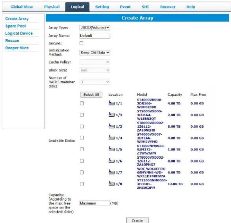
An array is a collection of physical disks that will be seen as one virtual drive by your Operating System (OS). The RS6614V/RS6618V capable of creating the following array types
Array Type:
- JBOD – Just a Bunch of Disks
● RAID 0 - Striping
● RAID 1 - Mirroring
● RAID 5 – Rotating Parity bit
● RAID 10 – Striping of Mirrored Drives
● RAID 50 – Striping of Distributed Parity
● RAID 6 – Double Parity Bit
Note: RS6614V does not support RAID50.
Array Name:
The name that will be displayed in Logical Device Information (Default:RAID_
Initialization Method:
- Keep Old Data: Opts to keep all the data on each drive untouched. Best for usersthat already have HighPoint RAID data on the selected drives.
-
Quick Init: Grants immediate access to the array volume. This option will deleteprevious user data, but will not build parity. Recommended for testing purposesonly or when new disks are used. Not recommended for RAID 5, RAID 50, and RAID 6.
-
Foreground: The array initialization process will be set at high priority. During this time array will be non-accessible, but initialization completion time will be shorter.
- Background: The array initialization process will have a lower priority. During this time array will be accessible, but initialization completion time will be longer.
Cache Policy (Default: Write Back)
- Write Back – Any data written to the array will be stored as cache, resulting in better I/O performance at the risk of data failures due to power outages. Data will be stored ascache before it is physically written to the disk; when a power outage occurs, any data in the cache will be lost.
- Write Through – Data written to an array is directly written onto the disk, meaning lower write performance for higher data availability. Without cache acting as a buffer, write performance will be noticeably slower but data loss due to power outages or other failures is significantly minimized.
Block Size (default: 64K)
• [64K, 128K are the supported block sizes]
This option allows you to specify the block size (also known as “stripe size”) for specificarray types (RAID 0, 1, 5, 6, 10, and 50). Adjusting the block size allows you to tailor thearray performance towards specific application. Consider the sizes of disk I/O data you are dealing with; as a general rule larger disk I/O may benefit from smaller block sizes, and smaller disk I/O may benefit from larger block sizes. A block size of 64 KB is recommended since it gives balanced performance for most applications.
Capacity (Default: Maximum)
The total amount of space you want the RAID array to take up. When creating RAID levels, disk capacities are limited by the smallest disk. Therefore, RAID 5 capacity will be [SMALLEST DISK CAPACITY] * (number of disks - 1).
Sector Size (Default: 512B)
This option is irrelevant for Windows XP 64 and later. Current OS already support larger volumes, and introduce a partitioning method known as GPT (GUID partition table). This option, also known as VSS (Variable Sector Size) allows you to specify the sector size of the array, for use with older Windows Operating Systems.
Normal Status
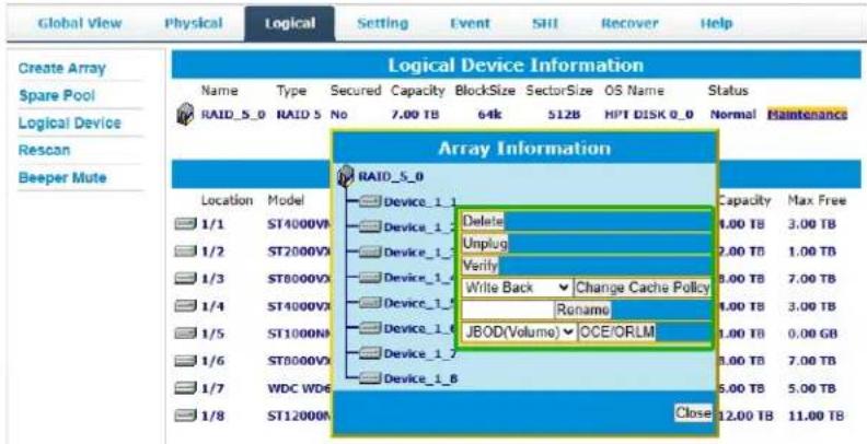
A Normal Status Array has the following options:
- Delete – deletes the selected RAID array
● Unplug – powers off the selected RAID array - Verify – verifies the integrity of the RAID array
- Change Cache Policy – Toggles between Write through and Write back cache
- Change Margin – Adjust margin when DV mode is enabled
- Rename – renames the RAID array
- OCE/ORLM – Online Capacity Expansion / Online RAID Level Migration
Critical Status
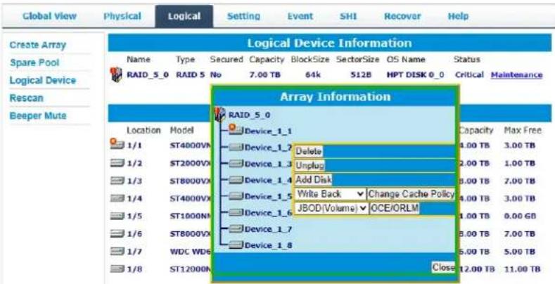
A critical status array has all the normal status options except the following:
● The Array can no longer be renamed
- Add disk replaces the verify disk option
Once array status changes to critical, the faulty disk will be taken offline and you caneither:
● Reinsert the same disk
- Insert new disk
Reinserting the same disk should trigger rebuilding status, since data on the disk would be recognized. If you insert a new disk, clicking add disk will give you the option to select that disk and add it to the array.
Disabled Status

A disabled status array means that your RAID level does not have enough disks to function.
- Your data will be inaccessible.
● Rebuilding will not trigger, since the RAID array does not have enough parity data to rebuild.
Your options in Maintenance are:
- Delete – will delete the array
- Unplug – will take array offline, making it safe to remove
- Recover – will attempt to recover the array using the list from the recover tab
Delete Array
Used to delete a created Array.
- Open the WebGUI.
- Click the Logical tab→Manintenance.
| Global View Physical Logical Device Information | |||||||
| Create Array Spare Pool Logical Device Rescan Beeper Mute | Name Type Secured Capacity BlockSize Sector Size OS Name Status RAID_5_0 RAID S No 7.00 TB 64k 512B HPT DISK 0_0 Normal Maintenance | ||||||
| Physical Device Information | |||||||
| Location Model | Secured | Capacity | Max Free | ||||
| 1/1 | ST4000VN000-2DR166-WDH0ZBBB | No | 4.00 TB | 3.00 TB | |||
| 1/2 | ST2000VX000-1CU164-W1E8N3QT | No | 2.00 TB | 1.00 TB | |||
| 1/3 | ST8000VX0002-1Z6112-ZA10NEH8 | No | 8.00 TB | 7.00 TB | |||
| 1/4 | ST4000VX007-2DT166-WDHJYVMQ | No | 4.00 TB | 3.00 TB | |||
| 1/5 | ST1000NM0033-9ZN173-21WSZGPN | No | 1.00 TB | 0.00 GB | |||
| 1/6 | ST8000VX0002-1Z6112-ZA10PMG7 | No | 8.00 TB | 7.00 TB | |||
| 1/7 | WDC WD6GEFRX-68MVMN1-WD-WX11D74RHV7A | No | 6.00 TB | 5.00 TB | |||
| 1/8 | ST1200NM0008-2H3101-ZHZCZPM | No | 12.00 TB | 11.00 TB | |||
- Click Delete to delete the RAID array.
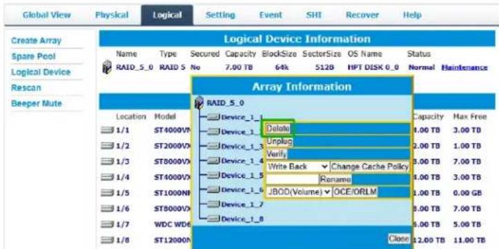
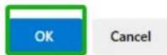
- A pop-up box pops up on the page, click OK to confirm the RAID deletion.
localhost:7402 says
All data on the array you selected will be deleted. Do you want to continue?
- There is no deleted RAID information at Logical Device Information, indicating that the RAID deletion operation is complete.
Notes:
When the RAID is in the rebuild, verify, foreground/background init status or be mounted, deleting the RAID will prompt in use.
When RAID is in rebuild, verify, foreground/background init status. If you want to delete the RAID, you can choose to stop the current operation and continue to delete the RAID.
When RAID is be mounted. If you want to delete the RAID, you can umount the RAID Array and continue to delete the RAID.
Logical Device Information
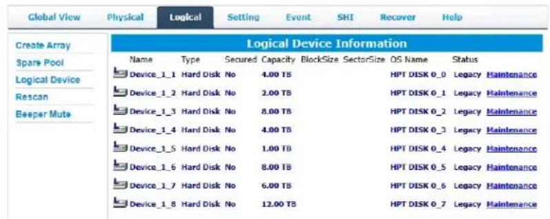
Logical device tab is the default page upon clicking the Logical tab of the WebGUI. Thispage contains information about your RAID arrays and individual disks your system detects.
Logical Device Information
Arrays you create and the properties associated with them will appear here.
Maintenance
Once an array has been created, click maintenance for options to manage your array.
Array Information
Clicking on the maintenance button will show you the Array information box. Different array statuses (Normal, critical, disabled) will have different maintenance options.
Physical Device Information
| Location | Model | Secured | Capacity | Max Free |
| 1/1 | ST4000VN008-2DR166-WDH0Z88B | No | 4.00 TB | 0.00 GB |
| 1/2 | ST2000VX000-1CU164-W1E8N3QT | No | 2.00 TB | 0.00 GB |
| 1/3 | ST8000VX0002-1Z6112-ZA10NEH8 | No | 8.00 TB | 0.00 GB |
| 1/4 | ST4000VX007-2DT166-WDH2VYMQ | No | 4.00 TB | 0.00 GB |
| 1/5 | ST1000NM0033-92M173-Z1W52GPN | No | 1.00 TB | 0.00 GB |
| 1/6 | ST8000VX0002-1Z6112-ZA10PMG7 | No | 8.00 TB | 0.00 GB |
| 1/7 | WDC WD6OEFRX-68MYMN1-WD-WX11D74RHV7A | No | 6.00 TB | 0.00 GB |
| 1/8 | ST12000NM0008-2H3101-ZHZOC2PM | No | 12.00 TB | 0.00 GB |
- Location – which Enclosure and port the drive is located in
- Model – model number of the drive connected
● Capacity – total capacity of the drive
● Max Free – total capacity that is not configured
Spare pool
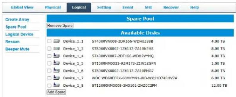
Spare disks are physical disks that will immediately replace critical disks in an array. Only redundant RAID arrays (RAID 1, 5, 6, 50, and 10) support spare drives.
Physical drives marked as a spare will automatically be added to an array whenever there is a disk failure. Having this feature minimizes the chances of a data loss by reducing the time an array is in critical status.
Add/Remove Spare Using WebGUI
- Log in WebGUI.
- Click Logical.
- Click Spare Pool.
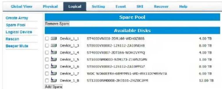
- Check the box for the disk you want as a spare from Available Disks.
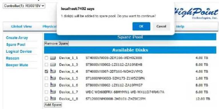
- Click Add Spare. Then click OK
- Disks that have been added to the Spare Pool are displayed in the Spare Pool.
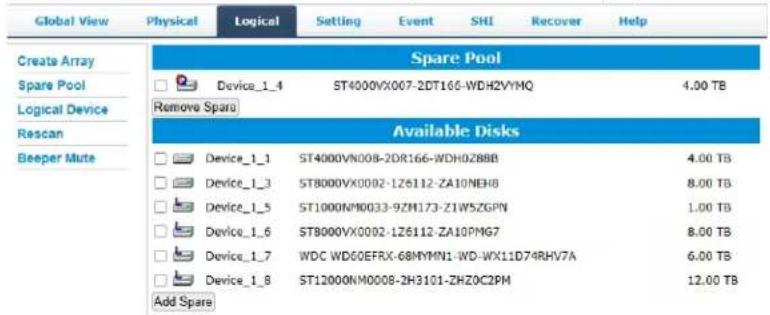
Note: Disks added to the spare pool will show under Spare Pool and can be removed by checking the disk checkbox from Spare Pool > Click Remove Spare.
Rescan
Clicking rescan will force drivers to report array status. For any disk(s) you hot pluginto the device, do not click rescan until all physical drives are detected and appearunder Logical Device Information.
Beeper Mute
The Enclosure will beep when the following conditions occur.
● Array falls into critical status
● Array falls into disabled status
- You unplug a disk
- Your disk fails due to bad sectors
● SMART sensors anticipate drive failure
If device is currently beeping, clicking Beeper Mute will mute the sound immediately. Note: This button does not permanently mute the alarm. To permanently mute the alarm go to Setting > Enable audible alarm > Disabled.
Note: Beeper off is permanently off.
Appendix A-4: Setting Tab
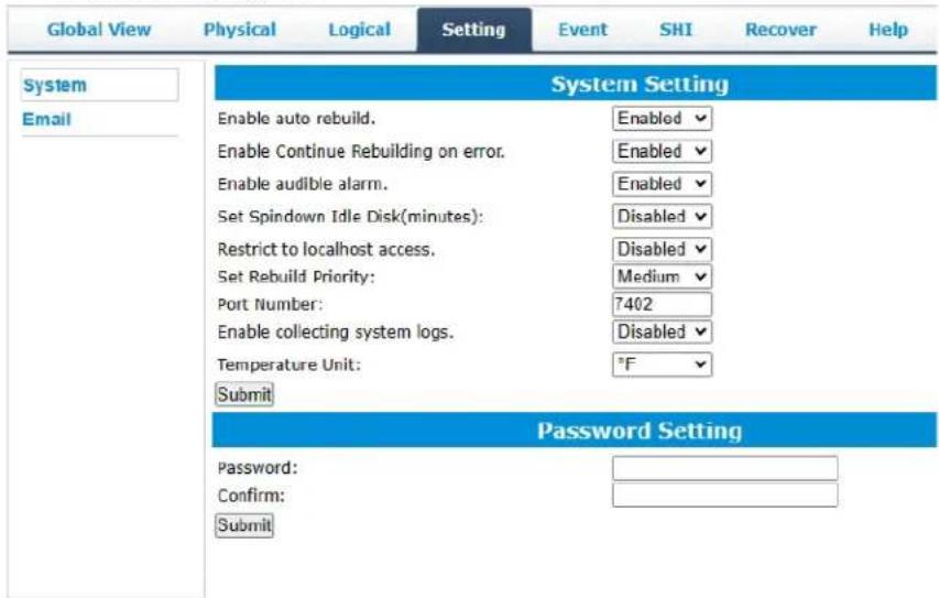
● Windows Setting Tab
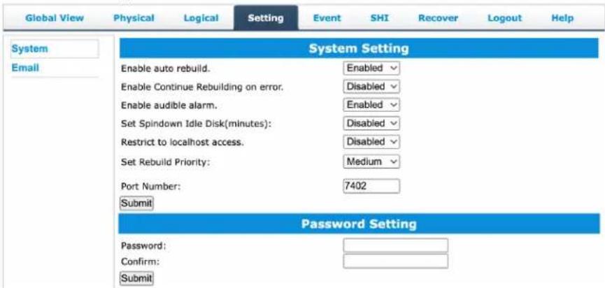
- Mac Setting Tab
- Linux Setting Tab
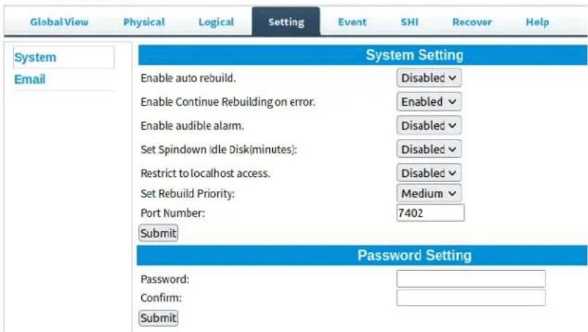
Under this tab, user can
- Enable auto-rebuilding
● Enable rebuilding on error
● Turn audible alarm on/off - Set spindown time for idle disks
- Restrict to localhost
- Set rebuild priority
● Change port number - Collecting system log ^1
- Change Temperature Unit ^1
● Change WebGUI password
Note: ^1 Only Windows supports this feature.
System Settings
Enable auto rebuild (default: Enabled)
When a physical drive fails, the controller will take the drive offline. Once you re-insert or replace the disk, the controller will not automatically rebuild the array unless this option is enabled.
Enable continue rebuilding on error (default: Enabled)
When enabled, the rebuilding process will ignore bad disk sectors and continue rebuilding until completion. When rebuild is finished, the data may be accessible but data inconsistency due to ignored bad sectors may cause problems in the future. If this option is enabled, HighPoint recommends user to check the event log for bad sectors.
Enable audible alarm (default: Disabled)
When a physical disk fails, the controller will emit an audible sound signaling failure. This option mutes the alarm.
Set Spindown Idle Disk (minutes) (default: Disabled)
When set, physical drives will spindown a certain amount of time after disk activity ceases. Only 10, 20, 30, 60, 120, 180, 240 minutes setting are available.
Restrict to localhost access (default: Disabled)
Remote access to the controller will be restricted when enabled, other users in your network will be unable to remotely log in to the WebGUI.
Rebuild Priority (default: Medium)
You can specify the amount of system resources you want to dedicate to rebuilding the array. There are 5 levels of priority [Lowest, Low, Medium, High, Highest]
Port Number (default: 7402)
The default port that the HighPoint WebGUI listens on is 7402. You may change it to any open port.
Enable collecting system logs (default: Disabled)
You can set it to enabled to collect system logs at any time. The collected system logs are stored on the C:/Windows/hpt_diagdriver. The maximum capacity of the collected system log is 800MB, and
parts exceeding 800MB will be overwritten forward.
Temperature Unit (default: °F)
The default temperature unit is Fahrenheit, you can change it to Celsius.
Password Setting

Changing your WebGUI password
Under Password Setting type your new password and confirm it, then click submit.
Recovering your HRM password
For Windows Users:
You can delete the file hptuser.dat. Then, restart the computer and open the WEBGUI to set a new password.
- Open File Explorer.
- Navigate to C:/Windows/
- Delete hptuser.dat.
- Reboot.
For Mac and Linux Users
After uninstalling the HighPoint RAID Management Software, re install the HighPoint RAID Management Software.
Email Setting
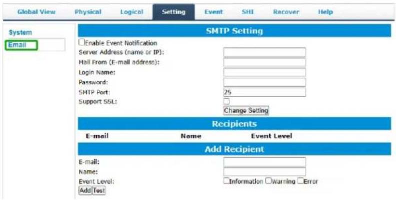
The following topics are covered under email:
- SMTP Setting
- Adding Recipients
You can set the controller to send an email out to recipients of your choosing whencertain events (refer to Event Tab) trigger.
SMTP settings
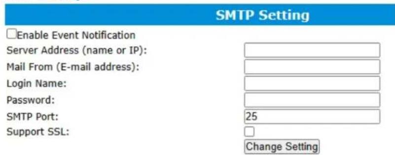
To set up email alerts:
- Check the Enable Event Notification box.
- Enter the ISP server address name or SMTP name.
- Type in the email address of the sender. (email account that is going to send thealert)
- Type in the account name and password of the sender.
- Type in the SMTP port (default: 25).
- Check support SSL box if SSL is supported by your ISP (port value will change to 465, refer to your ISP if you have a specific SMTP port.
Note: After you click 'Change Setting' the password box will become blank.
How to Add Recipients
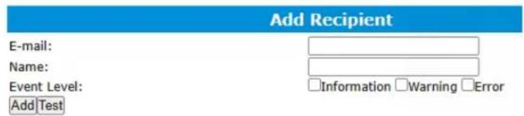
You can add multiple email addresses as receivers of a notice.
- Type the email of the recipient in the E-mail text box.
- Type the name of the recipient in the Name text box.
-
Check which type(s) of events will trigger an email in the respective Event Level check boxes.
-
(Optional) Click test to confirm settings are correct by sending out a test email.
-
Click add to add the recipient list.
-
The added recipient will display in under Recipients.
-
The email will send to your recipients the output recorded in the event log.
Example email message:
![HighPoint RAID Management Software Mail Notification Send: Mon 5/4/2015 4:36 PM To: test0 Mon, 04 May 2015 23:35:40 GMT: [HPTMV9580IOPController]: Plugging device detected.('WDC WD40EFRX-68WT0N0-WD-WCC4EHYCFZXL' at Controller2-Channel8)](/content/2026/05/958467/images/e8413f1a7c5b96fe18fcd15fe98e5dc5f71b32d9af78c334f0548ac4fb2ef50f.jpg)
Appendix A-5: Recover Tab
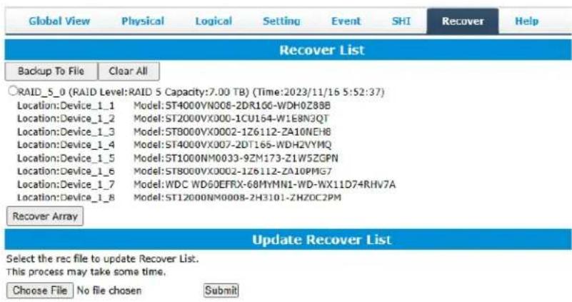
Previously created arrays will be stored under this tab. Recovering an array from herewill attempt to recover a "disabled" array and make it "normal".
The Recover List will list all your previous and current created arrays. Each entry will list the following properties:
- Array name
- RAID level
- Array Capacity
● Time created (YYYY/MM/DD, HH/MM/SS, 24 hr clock format) - Location of physical drives
● Model of physical drives
Important: When recovering an array, it is important to note the location and model of each physical drive because you can only recover using those exact positions and drivemodel.
How to Backup your Recover List
The recover list is a record of your previously created arrays containing the model and location information of your physical drives. Recovering from the list could help bringa disabled array back to normal status for emergency data retrieval.
To backup your recover list:
- Log in to WebGUI.
- Click Recover Tab.
- Click Backup to File.
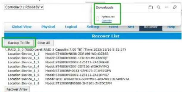
Note: The file will be saved as hptrec.rec.
How to Reload your Backup Recover List
In the case that you cleared the recover list or it does not appear for any reason, you can recover it if you saved the list beforehand.
To reload your recover list:
- Log in to WebGUI.
- Click Recover Tab.
- Under Update Recover List, click Choose File.

- Locate your previously saved hptrec.rec file and select it.
Note: loading a backup recover list will completely replace the current recover list.
- Click Submit.
Appendix A-6: Event Tab
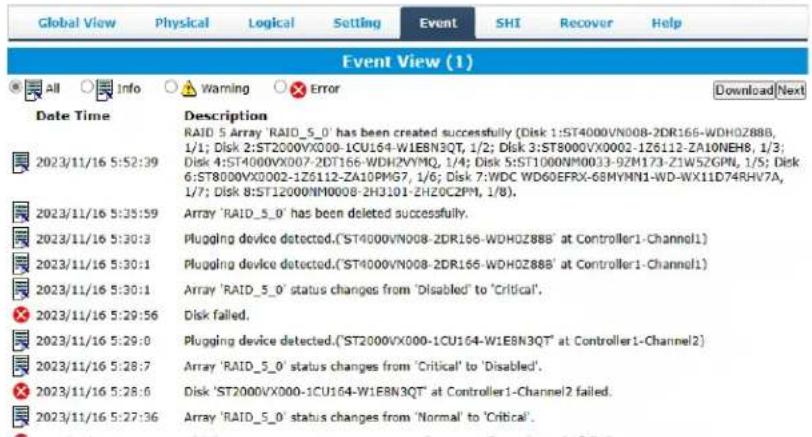
In the event tab, you can see log entries associated with the HighPoint device. The event log provides useful information when troubleshooting your set up.
In the event tab, there are four options available:
- Download – Save the log file on your computer
● Prev – View previous log page - Next – View next log page
Table 3. Event Log Icon Guide
| Icon | Name | Definition |
| Information | Includes general administrative tasks:Create/delete arraysConfiguring sparesRebuilding arraysConfiguring event notificationsConfiguring maintenance | |
| Warning | Alerts issued by the Host Adapter:High temperaturesSector errorsCommunication errorsVerification errors | |
| Error | Hardware related problemsHard disk failureBroken errorsMemory failure |
The event view is a basic error logging tool built into the HighPoint WebGUI.
Appendix A-7: SHI (Storage Health Inspector)
| Global View Physical Logical Setting Event SHI Recover Help | ||||||
| Storage Health Inspector(SHI) | ||||||
| Controller ID | Location# | Device Serial Number | RAID | *F | Bad Sectors Found & Repaired | S.M.A.R.T |
| 1 | 1 | WDH0Z88B | RAID_5_0 | 80 | None | Detail |
| 1 | 2 | W1E6N3QT | RAID_5_0 | 91 | 16 | Detail |
| 1 | 3 | ZA10NEH8 | RAID_5_0 | 100 | None | Detail |
| 1 | 4 | WDH2VYMQ | RAID_5_0 | 80 | 8 | Detail |
| 1 | 5 | Z1W5ZGPN | RAID_5_0 | 96 | None | Detail |
| 1 | 6 | ZA10PMG7 | RAID_5_0 | 104 | None | Detail |
| 1 | 7 | WD-WX11D74RHV7A | RAID_5_0 | 95 | None | Detail |
| 1 | 8 | ZHZ0C2PM | RAID_5_0 | 87 | None | Detail |
| HDD Temperature Threshold | ||||||
S.M.A.R.T Attributes
- HDD Temperature Threshold
● Storage Health Inspector Scheduling
The SHI outputs information collected using SMART (Self-Monitoring Analysis and Reporting Technology) Hard Drive Technology. The data provided on this tab helps youto anticipate any disk failures based on a variety of monitored hard disk properties.
(Refer to here)
Appendix A-8: Help
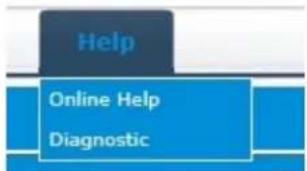
Online Help
Online Help redirects you to additional documentation concerning the HighPoint WebGUI. Diagnostic collect log information
Diagnostic View
- 1-Click Self-Diagnostic Solution: Diagnostic View provides a "1-click" information collection system for troubleshooting. It will gather all necessary hardware, software and storage configuration data and compile it into a single file, which can be transmitted directly to our FAE Team via our Online Support Portal.
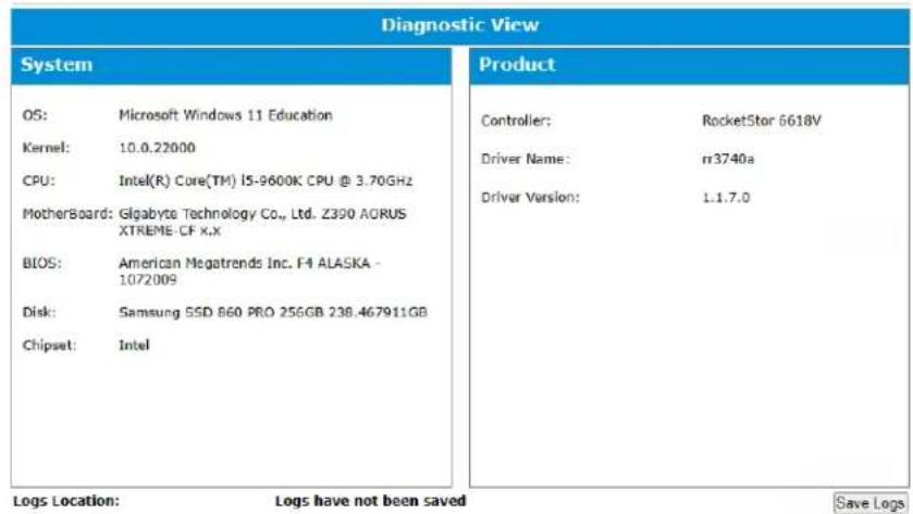
- You can also click "Help"→"Diagnostic" to enter the diagnostic view.
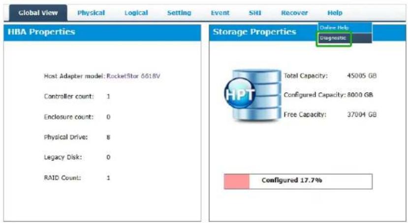
Log Saving
- Click the "Save Logs" button to create the diagnostic file.
- "Logs Location" will display the location of the saving path.
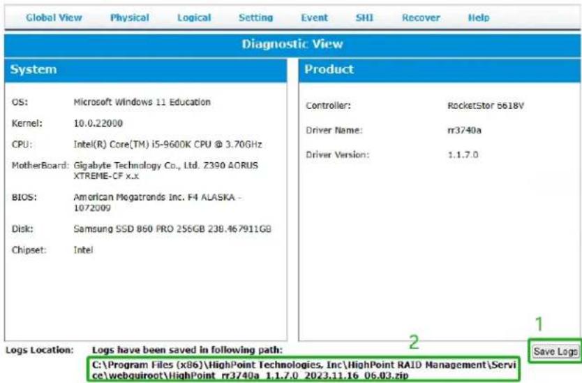
Appendix A-9: Logout
Logout of WebGUI, set password will appear.

Clicking "Logout" will safely exit "WebGUI".
Appendix B: WebGUI Icon Guide
| Critical – missing diskA disk is missing from the array bringing it to ‘critical’ status. The array is still accessible but another disk failure could result in data loss. | |
| VerifyingThe array is currently running a disk integrity check. | |
| RebuildingThe array is currently rebuilding meaning you replaced a failed disk or added a new disk to a ‘critical’ state array. | |
| Critical – rebuild requiredThe array has all disks, but one disk requires rebuilding. | |
| DisabledThe icon represents a disabled array, meaning more than one disk failed and the array is no longer accessible | |
| InitializingThe array is initializing. The two types of initialization is Foreground and Background. (See Initialization) | |
| UninitializedThe array initialization process has been interrupted, and the process is incomplete. | |
| Not InitializedDisk is not initialized yet, and needs to be initialized before use | |
| OCE/ORLMArray is performing a OCE/ORLM operation | |
| OCE/ORLM has stoppedThe array expansion process has been stopped. | |
| LegacyAn existing file system has been detected on the disk. These disks are classified as legacy drives. | |
| SpareThe device is a spare drive, it will automatically replace any failed drive part of an array. | |
| NormalThe array status is normal | |
 | InitializingThe array is initializing, either foreground or background initialization |
| [AWVHK] | Initialization StoppedThe initialization has been stopped. Current status is uninitialized. |
| [CC80] | Critical – InconsistencyData in the array is inconsistent and needs to be rebuilt. |
 | Critical – missing diskA disk has been removed or experienced failure, and user needs to reinsertdisk or add a new disk. |
| [CTWO] | RebuildingThe array is currently rebuilding. |
| [BBTT] | VerifyingThe array is performing a data consistency check. Array status will show ‘verifying’. |
| [DBHY] | DisabledThe array does not have enough disks to maintain the RAID level. Adisabled array is not accessible. |
| [W40X] | OCE/ORLMAray is expanding its capacity or migrating to a different raid level. Statuswill display ‘Expanding/Migrating’ |
 | OCE/ORLM stoppedThe ‘Expansion/Migrating’ process has been stopped. The status willdisplay ‘Need Expanding/Migrating’ |
| [ATW2] | Critical – OCE/ORLMA disk member is lost during the OCE/ORLM process. |
 | Critical – OCE/ORLM - rebuildThe expanding/migrating array requires a rebuild. |
Appendix C: RAID Level Reference Guide1
| Type | Description | Min. disks | Usable space | Advantage | Disadvantage | Application |
| JBOD | Just a bunch of disks | 1 | 100% | Each drive can be accessed as a single volume | No fault tolerance - failure of one drive results in complete data loss | Backup |
| RAID 0 | Disk Striping | 2 | 100% | Offers the highest performance | No fault tolerance - failure of one drive in the array results in complete datalose | Temporary file, performance driven application. |
| RAID 1 | Disk Mirroring | 2 | 50% | Provides convenient low-cost data redundancy for smaller systems and servers. Can handle1 disk failure. | Useable storage space is 50% of total available capacity. | Operating system, backup, and transaction database. |
| RAID 5 | Disk Striping with Rotating parity | 3 | 67-88% | High read performance, and medium write performance with data protection with a single drive failure. Can handle1 disk failure. | Not recommended for database applications that require frequent/heavy write sessions. | Data archives, and ideal for application that require data protection |
| RAID 6 | Disk Striping with dual rotating parity | 4 | 50-75% | High read performance, and medium write performance with data protection in case of up to two drives failure | Not recommended for applications that require frequent/heavy write sessions. | Data archives and ideal for application that requires data protection |
| RAID 10 | Disk Mirroring followed by stripe | 4 | 50% | High read performance and medium write performance with data protection for up to 2-drive failures | Useable storage capacity equals total capacity of alldrives in the array minus two | Fast database and application servers which need performance and data protection |
| RAID 50 | Disk Mirroring Followed by RAID5 | 6 | 67-75% | High read performance, and medium write performance for with data protection in case of up to two drives failure | Not recommended for applications that require frequent/heavy write sessions | Data archives and ideal for application that requires data protection |
^1 Refer to the RAID controller product specifications for supported RAID levels.
HighPoint List of Recommended Hard Drives
HighPoint maintains a list of tested hard drives suitable for RAID applications. Since not every hard drive in the market can be tested, this list is meant to be a general guideline for selecting hard drives operating in a RAID environment. Regular, desktopgrade drives are highly not recommended for RAID use.
Compatibility List:
https://www.highpoint-tech.com/rs661xv-series
Resource
A variety of manuals, guides and FAQs are available for the RocketStor 6614V/6618V. In addition, we recommend visiting the Software Downloads webpage for the management interfaces, and installation guides.
Software Download:
https://www.highpoint-tech.com/rs661xv-series
FAQ & Troubleshooting:
https://www.highpoint-tech.com/support-and-services
Customer Support
If you encounter any problems while utilizing the RocketStor 6614V/6618V, or have any questions about HighPoint Technologies, Inc. products & solutions, feel free to contact our Customer Support Department.
Web Support:
https://www.highpoint-tech.com/support-and-services
HighPoint Technologies, Inc. websites:
https://www.highpoint-tech.com
- RocketStor 6614V & 6618V User Manual
- Copyright
- Trademarks
- Notice
- FCC Part 15 Class B Radio Frequency Interference statement
- European Union Compliance Statement
- Table of Contents
- Product Overview
- Kit Contents
- RocketStor 6614V Kit Contents
- RocketStor 6618V Kit Contents
- Step 1: Install the RocketStor 6614V/6618V
- Take the RocketStor 6618V as an example.
- Step 2: Install/Update Drivers
- For Windows Users
- For Mac Users
- For Linux Users
- tar zxvf RR37xx\_8xx\_28xx\_Linux\_X86\_64\_Src\_vx.x.x\_xx\_xx\_xx.tar.gz
- sh rr37xx\_8xx\_28xx\_linux\_src\_vx.x.x\_xx\_xx.xx.bin
- Uninstall Drivers
- Step 3: Install HighPoint RAID Management Software (WebGUI & CLI)
- Double-click HighPoint RAID Management.exe.
- ./RAID_Manage_Linux_vx.x.x_xx_xx_xx.bin
- Uninstall HighPoint RAID Management (WebGUI & CLI)
- dpkg -r hptsvr (or rpm -e hptsvr-https)
- Step 4A: Login WebGUI
- For Windows/Mac Users
- Step 4B: Login CLI
- Step 5A: Create RAID Arrays using WebGUI
- For Windows, Mac and Linux Users
- Step 5B: Create RAID Arrays using CLI
- For Windows and Linux Users
- Step 6: Initialize and format the RAID Array
- Erase "HPT DISK 2\_0 Media"?
- Erasing "HPT DISK 2\_0 Media" and creating "Tutorial\_array"
- Step 7: Manage your RAID array
- RAID Spare Pool
- Add/Remove Spare Using WebGUI
- Email Notifications
- SMTP settings
- Email Precautions
- Outlook Setting:
- Notes:
- Adding Email Recipients
- Close
- WebGUI Remote Login
- Storage Health Inspection (SHI)
- HDD Temperature Threshold
- Storage Health Inspector Scheduling
- Click Submit.
- Your entry will appear under Tasks List.
- RAID Expansion (OCE/ORLM)
- OCE – Online Capacity Expansion
- ORLM – Online RAID Level Migration
- Take ORLM for example.
- Troubleshooting – Hardware
- Enclosure Mute Button
- LED Activity
- Replacing a Failed Disk
- Troubleshooting - Software
- Troubleshooting – RAID
- Rebuild failed
- Critical array becomes disabled when faulty disk was removed
- Disabled Arrays
- Recover with RAID Maintenance
- Recover RAID with Recover Tab
- Online Array Roaming
- Appendix A-1: Global View Tab
- Take RocketStor 6618V as an example.
- HBA Properties
- Storage Properties
- Physical Devices Information
- Notes :
- Read Ahead
- Write Cache
- NCQ (Native Command Queuing)
- Identify LED
- Rescan
- Array Type:
- Array Name:
- Initialization Method:
- Cache Policy (Default: Write Back)
- Block Size (default: 64K)
- • [64K, 128K are the supported block sizes]
- Capacity (Default: Maximum)
- Sector Size (Default: 512B)
- Delete Array
- localhost:7402 says
- Logical Device Information
- Maintenance
- Array Information
- Physical Device Information
- Beeper Mute
- Appendix A-4: Setting Tab
- ● Windows Setting Tab
- - Mac Setting Tab
- - Linux Setting Tab
- System Settings
- Enable auto rebuild (default: Enabled)
- Enable continue rebuilding on error (default: Enabled)
- Enable audible alarm (default: Disabled)
- Set Spindown Idle Disk (minutes) (default: Disabled)
- Restrict to localhost access (default: Disabled)
- Rebuild Priority (default: Medium)
- Port Number (default: 7402)
- Enable collecting system logs (default: Disabled)
- Temperature Unit (default: °F)
- Password Setting
- Changing your WebGUI password
- Recovering your HRM password
- For Windows Users:
- For Mac and Linux Users
- Email Setting
- How to Add Recipients
- Appendix A-5: Recover Tab
- How to Backup your Recover List
- How to Reload your Backup Recover List
- Appendix A-6: Event Tab
- Appendix A-7: SHI (Storage Health Inspector)
- Appendix A-8: Help
- Online Help
- Diagnostic View
- Log Saving
- Appendix A-9: Logout
- HighPoint List of Recommended Hard Drives
- Resource
- Customer Support
Brand : Highpoint
Model : RocketStor 6618V
Category : Hard Drive