Sharpy X Frame FD - Lighting Claypaky - Free user manual and instructions
Find the device manual for free Sharpy X Frame FD Claypaky in PDF.


| Product Type | Moving head spotlight with framing system |
| Brand | Claypaky |
| Model | Sharpy X Frame FD |
| Dimensions (L x W x H) | 400 x 350 x 600 mm (head only) |
| Weight | 22 kg |
| Power Supply | AC 100-240V, 50/60 Hz, 800 W |
| Light Source | Philips MSD Platinum 300W (or equivalent) |
| Pan Range | 540° |
| Tilt Range | 270° |
| Framing System | 4 individually controllable shutter blades, rotatable ±45° |
| Color Wheel | 14 fixed colors + open, split color effect |
| Gobo Wheel | 17 fixed gobos + open, rotating gobo slot |
| Prism | Triple-facet rotating prism (optional) |
| Dimmer | 0-100% continuous dimming |
| Strobe | 0-20 Hz, pulse effects |
| DMX Channels | 16, 20, or 24 channels (selectable) |
| Cooling | Fan cooled, forced ventilation |
| Maintenance | Clean lens with dry cloth; check air filters monthly; relamp after 1000 hours |
| Safety | Use safety cable; disconnect power before servicing; mount securely |
| Spare Parts & Repairability | Contact authorized dealer for genuine parts; user-replaceable lamp and fuses |
| General Information | For indoor use only; IP20 rating; ambient temperature max 45°C |
Frequently Asked Questions - Sharpy X Frame FD Claypaky
User questions about Sharpy X Frame FD Claypaky
0 question about this device. Answer the ones you know or ask your own.
Ask a new question about this device
Download the instructions for your Lighting in PDF format for free! Find your manual Sharpy X Frame FD - Claypaky and take your electronic device back in hand. On this page are published all the documents necessary for the use of your device. Sharpy X Frame FD by Claypaky.
USER MANUAL Sharpy X Frame FD Claypaky
natural_image
Line drawing of a mechanical device resembling a gamma-ray or radar light (no text or symbols)| INDEX | |
| Page | Contents |
| 2 | 1. Safety information |
| 3 | 2. Unpacking and preparation |
| 4 | 3. Installation and start-up |
| 4 | 3.1 Installing the fixture |
| 5 | 3.2 Connecting to manis supply |
| 5 | 3.3 Connecting the control signal line: DMX / Art-Net |
| 6 | 3.4 Switching on the fixture and basic SetUp |
| 8 | 4. Maintenance |
| 8 | 4.1 Opening the covers |
| 9 | 4.2 Periodical cleaning |
| 10 | 4.3 Effects module removal |
| 14 | 4.4 Rotating gobos |
| 15 | 4.5 Battery removal |
| 16 | 5. Dimensions |
| 16 | 6. Cause and solution of problems |
Congratulations on choosing a Claypaky product! We thank you for your custom.
Please note that this product, as all the others in the rich Claypaky range, has been designed and made with total quality to ensure excellent performance and best meet your expectations and requirements.
1. SAFETY INFORMATION
EN
SAFETY INFORMATION
IMPORTANT: Claypaky recommends you carefully read and keep the safety information on this product, also available in digital format at the following link:
www.claypaky.com
Ref: FIS027 - Safety Information Sharpy X Frame / FD
IT
Ref: FIS027 - Safety Information Sharpy X Frame / FD
ES
Ref: FIS027 - Safety Information Sharpy X Frame / FD
FR
CONSIGNES DE SÉCURITÉ
natural_image
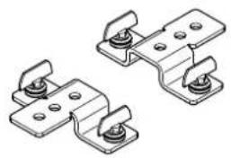
Technical line drawing of two mechanical clamping components with mounting holes (no text or symbols)2 x 183102/805
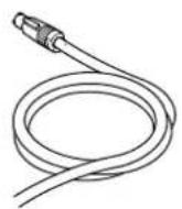
Packing contents - Fig. 1
2
3
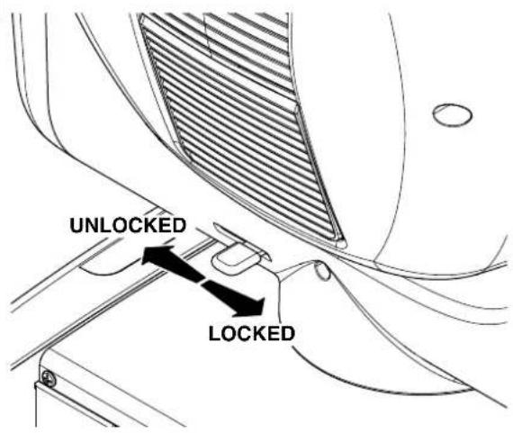
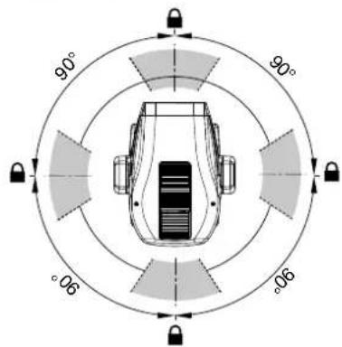
PAN Mechanism Lock and Release (every 90°) - Fig. 2
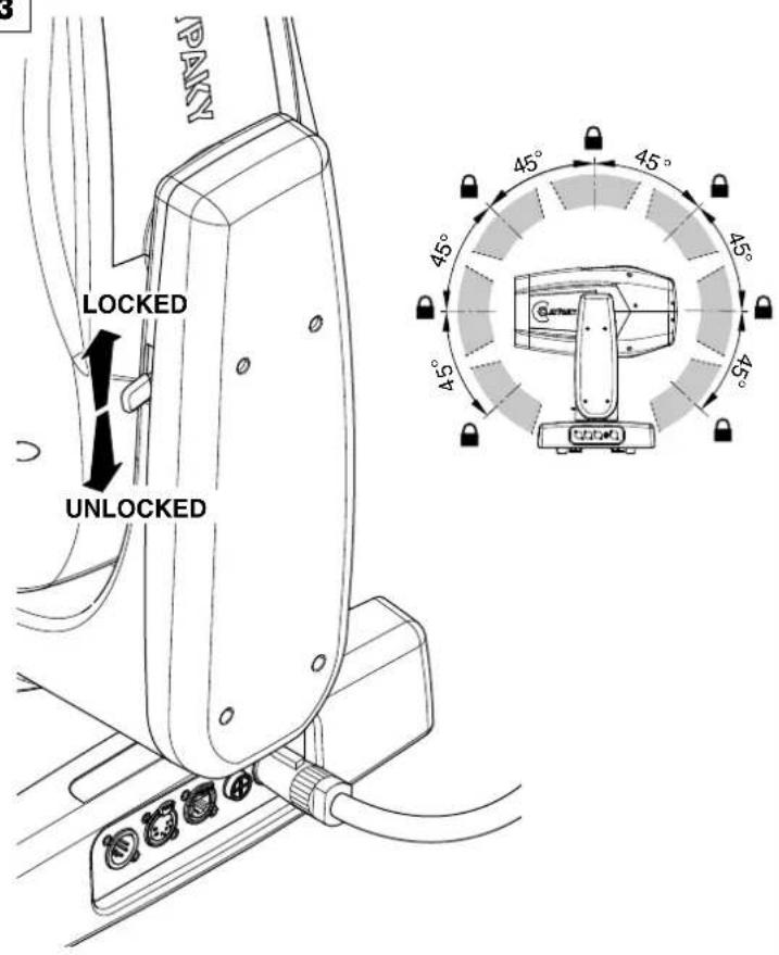
TILT Mechanism Lock and Release (every 45°) - Fig. 3
3. INSTALLATION AND START-UP
3.1 Installing the fixture
4
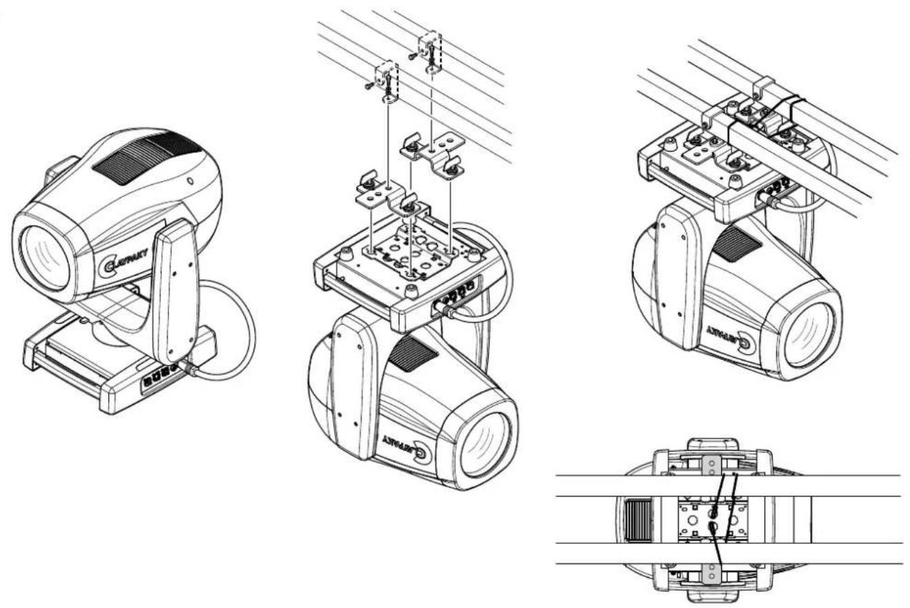
Installing the projector - Fig. 4
The projector can be installed on the floor resting on special rubber feet, on a truss or on the ceiling or wall.
WARNING: with the exception of when the projector is positioned on the floor, the safety cable must be fitted. (Cod. 105041/003 available on request).
This must be securely fixed to the support structure of the projector and then connected to the fixing point at the centre of the base.
5
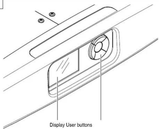
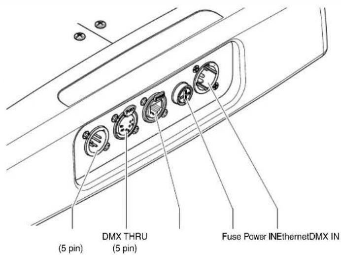
Control panel - Fig. 5
3.2 Connecting to manis supply
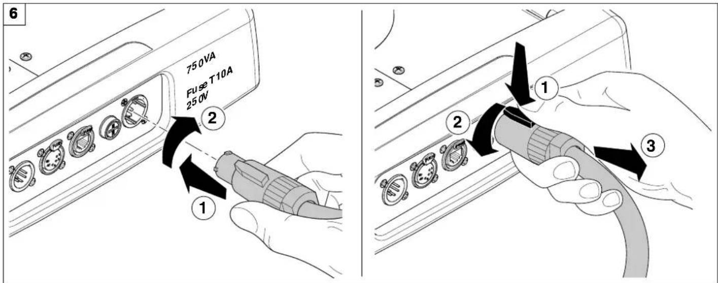
Connecting and disconnecting power cable - Fig. 6
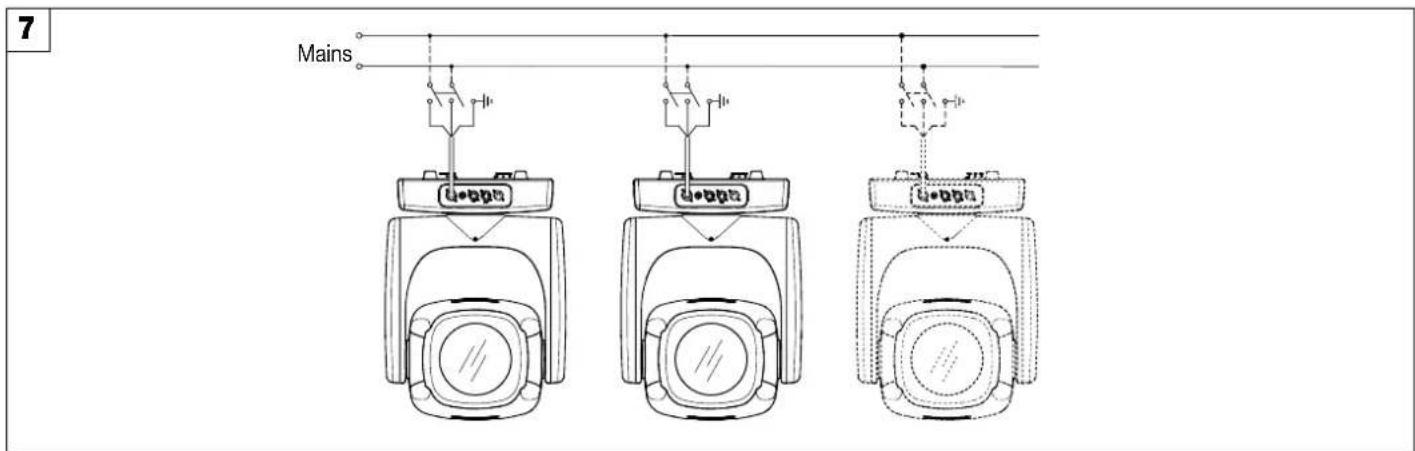
Connecting to the mains supply - Fig. 7
3.3 Connecting the control signal line: DMX / Art-Net
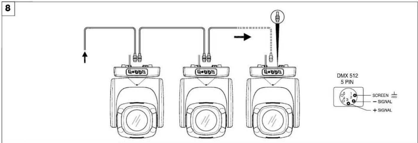
Connecting to the control signal line (DMX) - Fig. 8
Use a cable conforming to specifications EIA RS-485: 2-pole twisted, shielded, 120Ohm characteristic impedance, 22-24 AWG, low capacity. Do not use microphone cable or other cable with characteristics differing from those specified. The end connections must be made using XLR type 5 pin male/female connectors. A terminating plug must be inserted into the last projector with a resistance of 120Ohm (minimum 1/4 W) between terminals 2 and 3.
IMPORTANT: The wires must not make contact with each other or with the metal casing of the connectors. The casing itself must be connected to the shield braid and to pin 1 of the connectors.
3.4 Switching on the fixture and basic SetUp
9
Switching on the projector - Fig. 9
Switch-on the fixture. The projector starts resetting the effects. At the same time, the following information scrolls on the display:

Model Sharpy X Frame
Firmware Version X.X.X Date - Hour
Dmx Address xxx
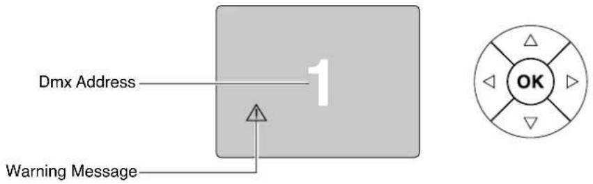
On conclusion of resetting in case of absence of the dmx signal, Pan and Tilt move to the "Home" position (Pan 128 bit - Tilt 128 bit). The control panel (Fig. 8) has a display and buttons for the complete programming and management of the projector menu. The display can be in one of two conditions: rest status and setting status. When it is in the rest status, the display shows the projector's DMX address.
During menu setting status, after a wait time (about 30 seconds) without any key having been pressed, the display automatically returns to rest status. It should be noted that when this condition occurs, any possible value that has been modified but not yet confirmed with the OK key will be cancelled.
10
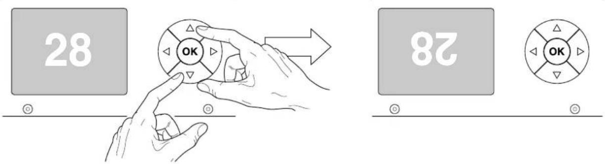
Reversal of the display - Fig. 10
To activate this function, press UP ⚙ and DOWN ⚙ keys simultaneously while the display is in the rest mode. This status will be memorised and maintained even for the next time it will be switched on. To return to the initial state, repeat the operation all over again.
Setting the projector starting address
On each projector, the starting address must be set for the control signal (addresses from 1 to 512).
The address can also be set with the projector switched off.
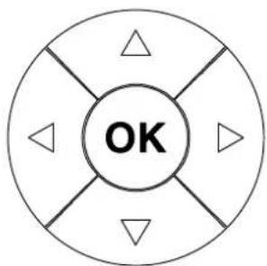
Functions of the buttons - Using the menu
flowchart
graph TD
    A["OK"] --> B["Arrow Up"]
    A --> C["Arrow Down"]
    A --> D["Arrow Left"]
    A --> E["Arrow Right"]

Confirms the displayed value, or activates the displayed function, or enters the successive menu.

Decreases the value displayed (with auto-repetitions) or passes to the next item in the menu.
DOWN

Increases the value displayed (with auto-repetitions) or passes to the previous item in a menu.

Return to the top level

Enters the successive menu.
RIGHT
USING THE MENU:
1) Press LEFT ◆ once - "Main Menu" appears on the display.
2) Use the UP ⬆ and DOWN ⬇ keys to select the menu to be used:
- Setup (Setup Menu): To set the setting options.
- Option (Option Menu): To set the operating options
- Informations (Informations Menu): To read the counters, software version and other information.
- Manual Control (Manual control Menu): To trigger the test and manual control functions.
- Test (Test Menu): To check the proper functioning of effects
- Advanced (Advanced Menu): Access to the "Advanced menu" is recommended for a trained technical personnel.
3) Press OK to display the first item in the selected menu.
4) Use the UP ⬆ and DOWN ⬇ keys to select the MENU items.
Setting addresses and options with the projector disconnected
The projector's DMX address, as well as other possible operating options, can also be set when the appliance is disconnected from the electricity supply. All that is needed is to press RIGHT ☑ to momentarily activate the display and thus access the settings. Once the required operations have been carried out, the display will switch off again after a wait time of 30 seconds.
4. MAINTENANCE
4.1 Opening the covers
1112
natural_image
Technical line drawing of a portable air conditioner unit with labeled component (no text or symbols beyond label)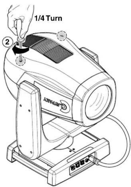
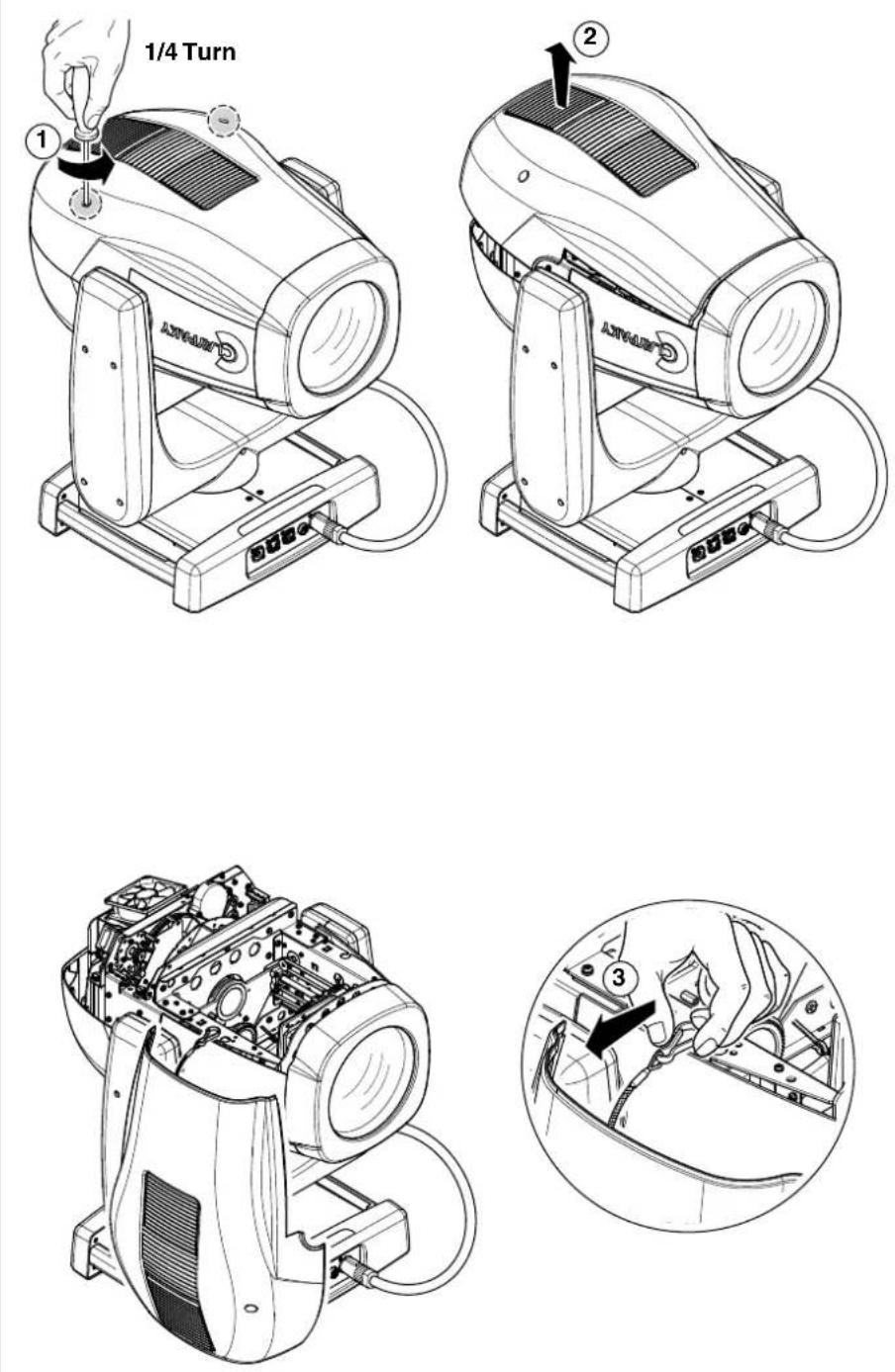
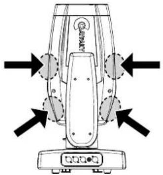
Locking and releasing Pan and Tilt movements - Refer to the instructions in the UNPACKING AND PREPARATION section.
Opening the head covers - Fig. 11.
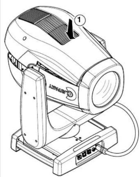
Closing the head covers - Fig. 12.
4.2 Periodical cleaning
13
NOTE: keep a careful cleaning of the "CMY/colour filters assembly" to prevent rapid deterioration.

Light collimation system
This product contains internal light collimation system.
Avoid intense light from any angle.
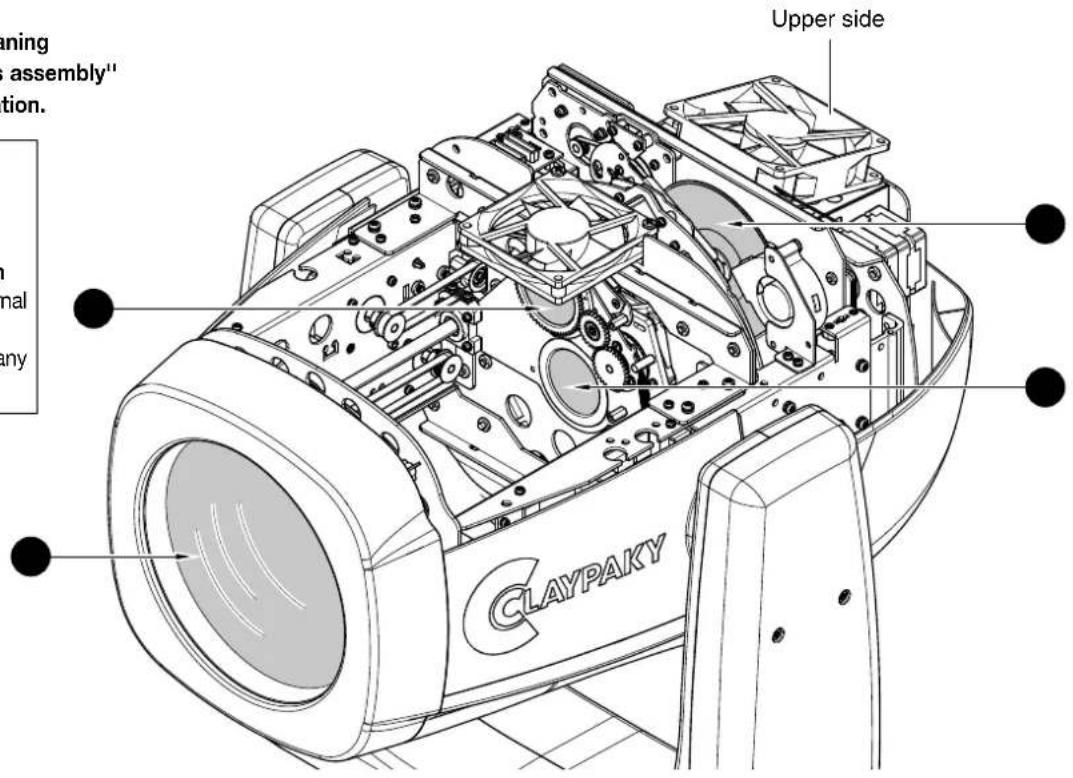
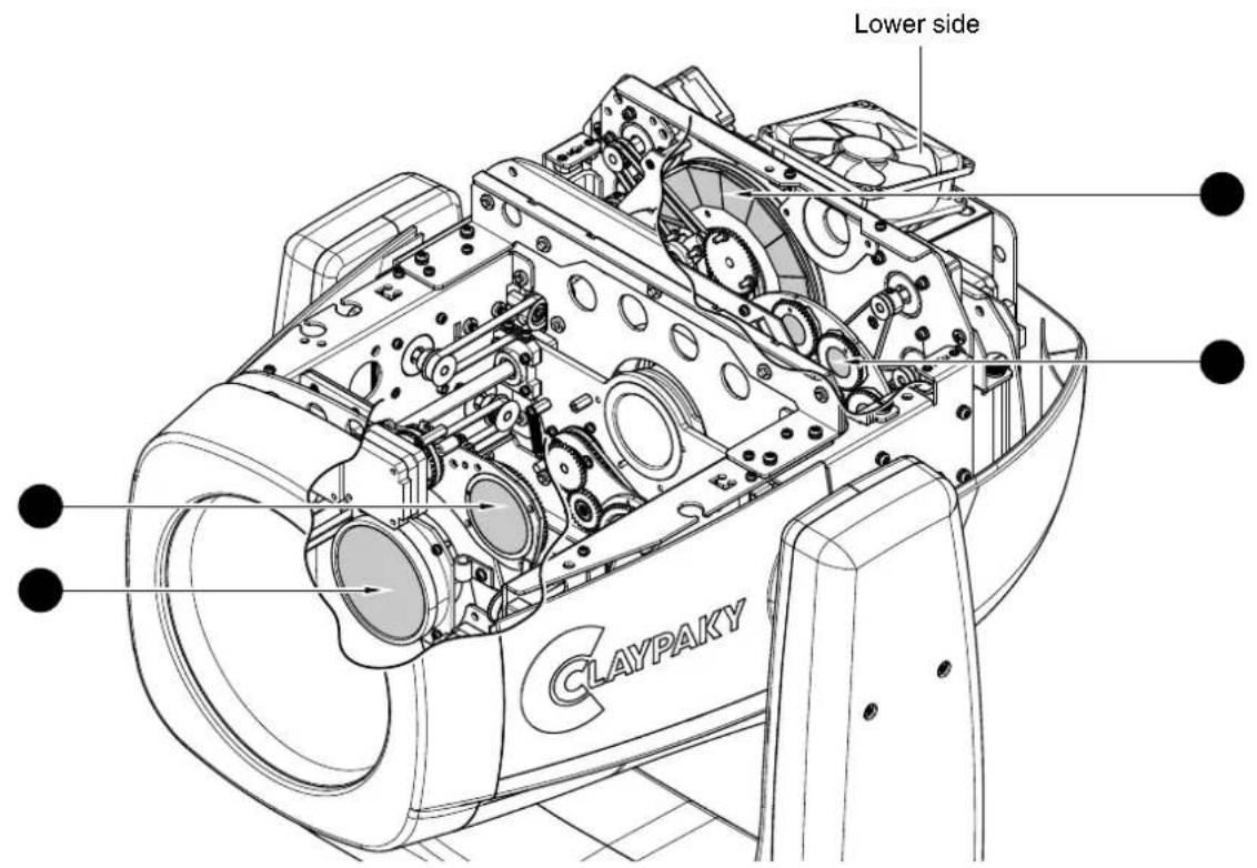
Periodical cleaning - Fig. 13
To ensure optimal operation and performance for a long time it is essential to periodically clean the parts subject to dust and grease deposits. The frequency with which the following operations are to be carried out depends on various factors, such as the amount of the effects and the quality of the working environment (air humidity, presence of dust, salinity, etc.).
Use a soft cloth dampened with any detergent liquid for cleaning glass to remove the dirt from the reflectors, from the lenses and filters. It is recommended that the projector undergoes an annual service by a qualified technician for special maintenance involving at least the following operations:
- General cleaning of internal parts.
- Restoring lubrication of all parts subject to friction, using lubricants specifically supplied by Claypaky.
- General visual check of the internal components, cabling, mechanical parts, etc.
- Electrical, photometric and functional checks; eventual repairs.
4.3 Effects module removal
14
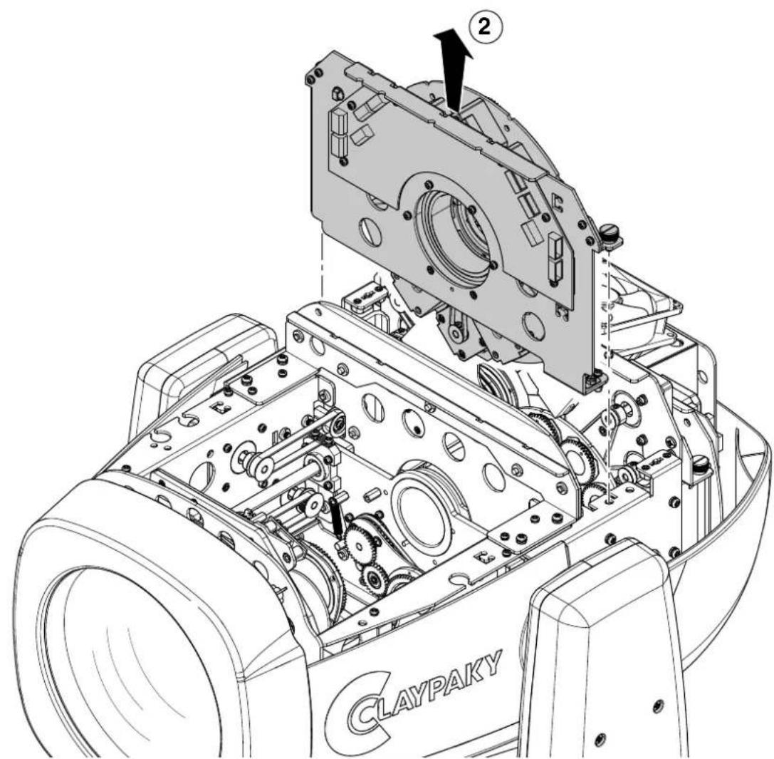
Extraction of the effect modules - Fig. 14.
IMPORTANT: Grasp the modules using the support structure and not the details which could get damaged.
Insertion of the effect modules: Repeat the operations indicated in Fig. 14, 15 and 16 in reverse order.
15
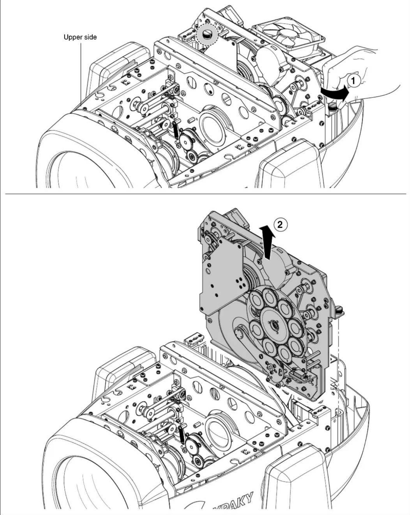
Extraction of the effect modules - Fig. 15.
IMPORTANT: Grasp the modules using the support structure and not the details which could get damaged.
Insertion of the effect modules: Repeat the operations indicated in Fig. 14, 15 and 16 in reverse order.
16
natural_image
Technical line drawing of a mechanical device with directional arrows indicating movement or force (no text or symbols)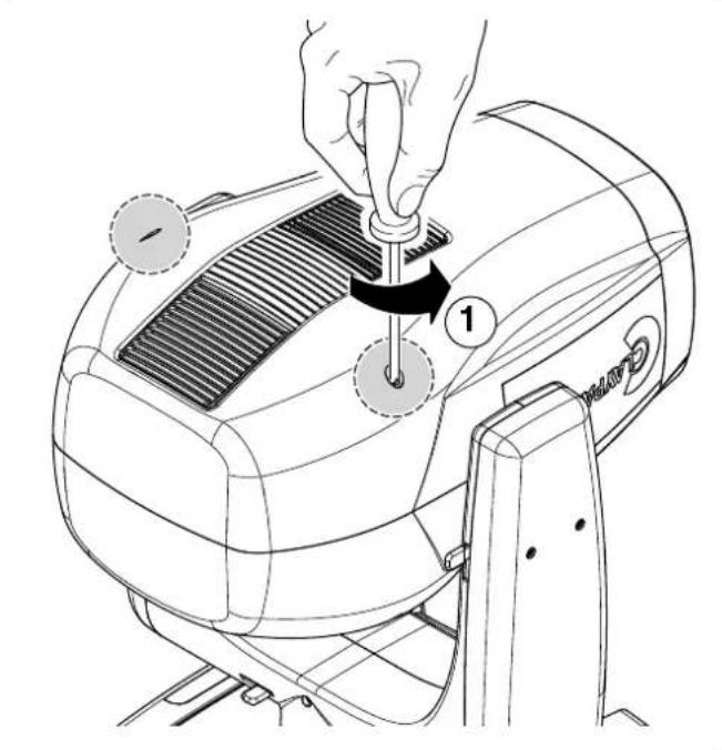
natural_image
Line drawing of a hairdryer machine with a hand adjusting the comb (no text or symbols present)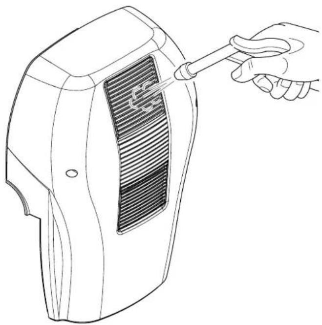
natural_image
Line drawing of a handheld device with a hand holding a screwdriver touching its grille (no text or symbols)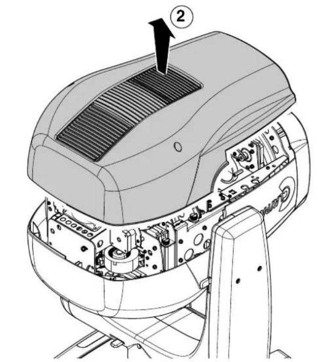
natural_image
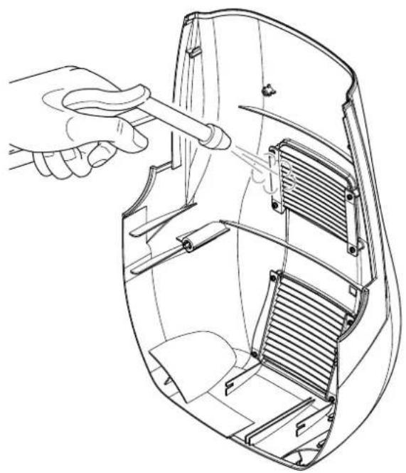
Technical line drawing of a mechanical component with a hand adjusting a tool (no text or symbols present)Cleaning of the grids - Fig. 16.
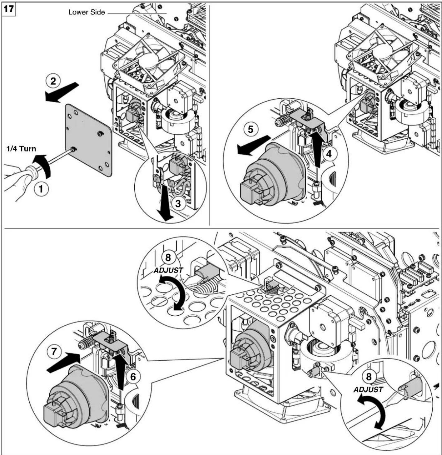
Lamp change - Fig 17.
Take the new lamp out of its package and insert in the fitting.
WARNING: do not touch the lamp's envelope with bare hands. Should this happen, clean the bulb with a cloth soaked in alcohol and dry it with a clean, dry cloth.
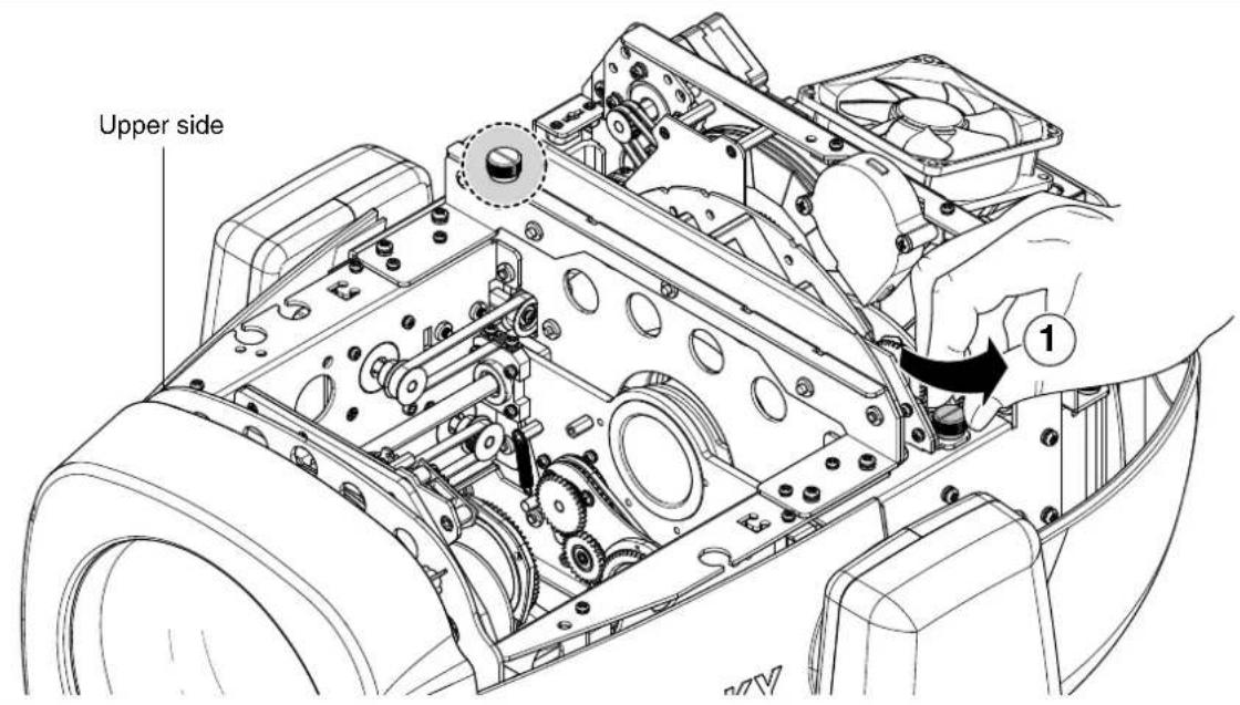
Lamp regulation
To centre the lamp, turn the adjusting screw as shown in the figure.
WARNING: The lamp must be adjusted with the projector switched off. After adjusting, close the effects covers, switch on the projector and check that the adjustment has been correctly made. If necessary, switch off the projector, remove the effects covers and repeat lamp adjustment.
REMARK:
- Lifetime of the lamp will be influenced by the switching cycle.
- After a successful starting, attempt to keep the lamp burning for at least 15 minutes in order to complete the chemical cycle of the lamp to secure the lifetime.
- After switching-off the lamp wait at least 2 minutes before switching-on it again.
4.4 - Rotating gobos
18
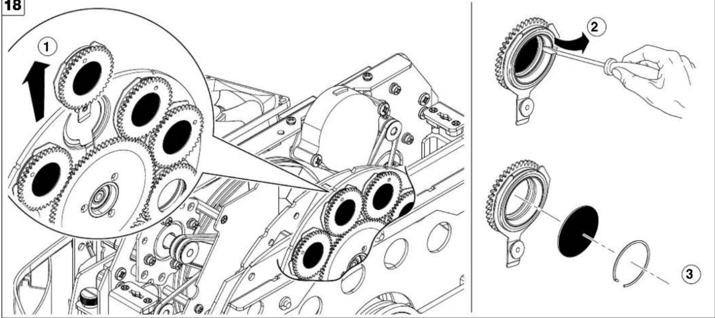
Bearing group replacement - Fig. 18
19
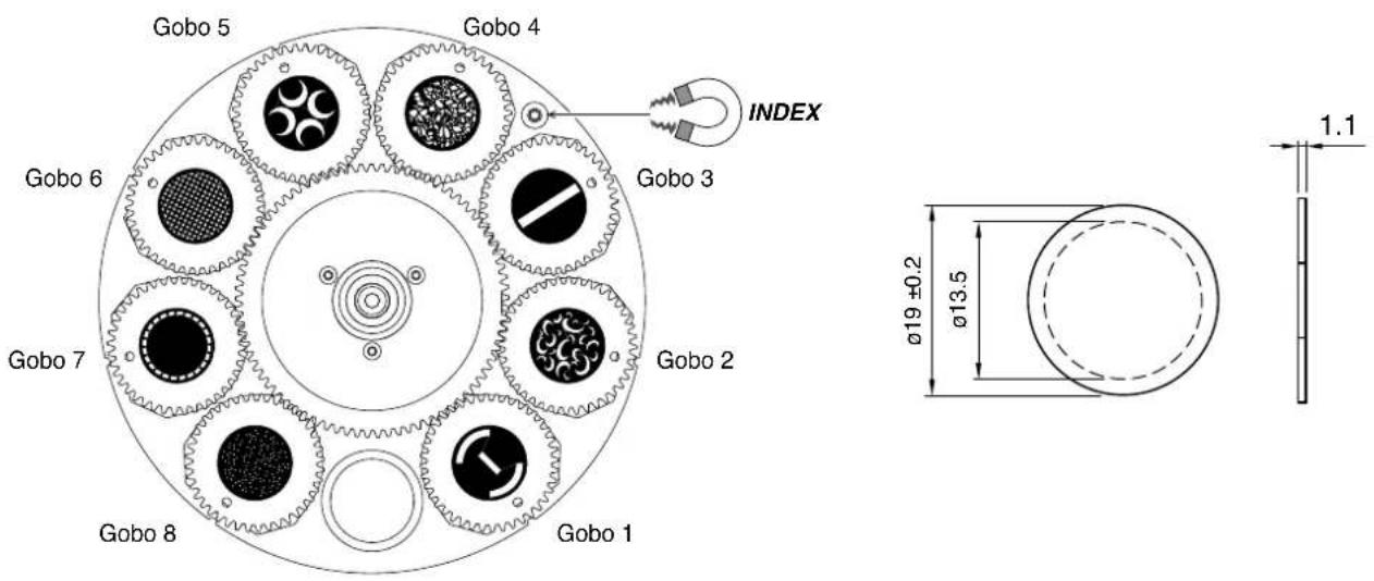
Replacing rotating gobos (ø 19 mm - max 13.5 mm image - thickness 1.1 mm) - Fig. 19
- The rotating gobo wheel only use dichroic glass gobos (it is not possible to use metal gobos);
- For more information contact Claypaky;
20
COATED GLASS GOBOS TYPE 1 COATED GLASS GOBOS TYPE 2
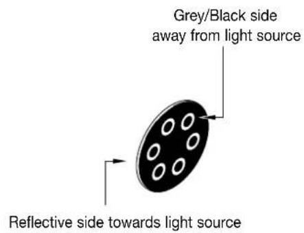
Coated side towards light source
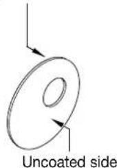
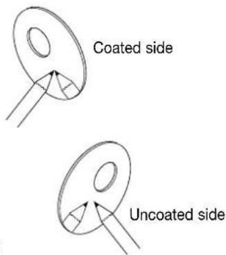
To determine which side of a godo is coated, hold an odject up to it. On the uncoated side, there is a space between the object and its reflection.
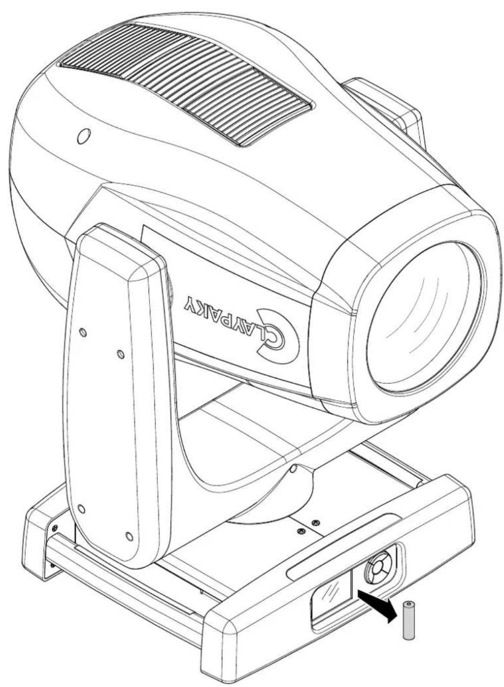
4.5 - Battery removal
21
natural_image
Line drawing of a C45PARKY industrial machine with mounting base and control panel (no text or symbols)
This product contains a rechargeable battery. To preserve the environment, please dispose the battery at the end of its life according to the regulation in force.
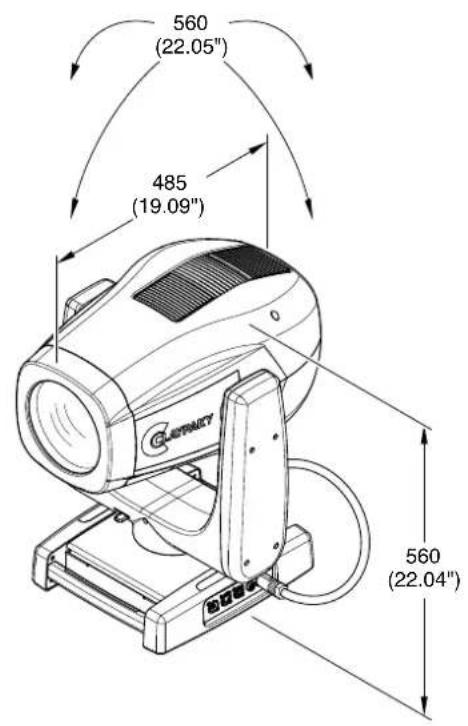
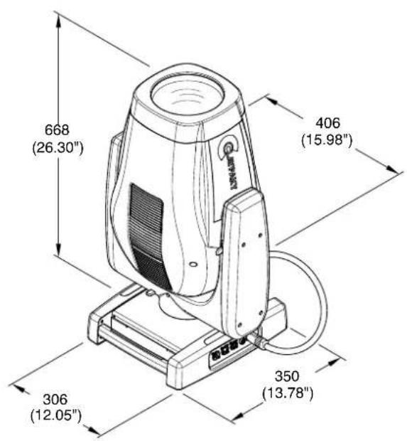
5. DIMENSIONS
6. CAUSE AND SOLUTION OF PROBLEMS
| THE PROJECTOR WILL NOT SWITCH ON | PROBLEMS | ||||
| ELECTRONICS NON-OPERATIONAL | |||||
| DEFECTIVE PROJECTION | |||||
| REDUCED LUMINOSITY | |||||
| POSSIBLE CAUSES CHECKS AND REMEDIES | |||||
| ● | No mains supply. | Check the power supply voltage. | |||
| ● | ● Light source exhausted or defective. | Call an authorised technician. | |||
| ● | Signal transmission cable faulty or disconnected. | Replace the cables. | |||
| ● | Incorrect addressing. | Check addresses (see instructions). | |||
| ● | Fault in the electronic circuits. | Call an authorised technician. | |||
| ● | Lenses broken | Call an authorised technician. | |||
| ● | ● Dust or grease deposited. | Clean (see instructions). | |||
- SAFETY INFORMATION
- EN
- SAFETY INFORMATION
- IT
- ES
- FR
- CONSIGNES DE SÉCURITÉ
- INSTALLATION AND START-UP
- Installing the fixture
- Connecting to manis supply
- Connecting the control signal line: DMX / Art-Net
- Switching on the fixture and basic SetUp
- Switching on the projector - Fig. 9
- Reversal of the display - Fig. 10
- Setting the projector starting address
- Functions of the buttons - Using the menu
- USING THE MENU:
- Setting addresses and options with the projector disconnected
- MAINTENANCE
- Opening the covers
- Periodical cleaning
- 13
- Light collimation system
- Periodical cleaning - Fig. 13
- Effects module removal
- Lamp regulation
- REMARK:
- - Rotating gobos
- - Battery removal
- DIMENSIONS
- CAUSE AND SOLUTION OF PROBLEMS
Brand : Claypaky
Model : Sharpy X Frame FD
Category : Lighting