
RK3236BKF - Meuble informatique StarTech.com - Free user manual and instructions
Find the device manual for free RK3236BKF StarTech.com in PDF.


| Product Type | 32U Knock-Down Server Rack Cabinet |
| Brand | StarTech.com |
| Model | RK3236BKF |
| Color | Black |
| Form Factor | Knock-Down (KD) Assembly |
| Material | Steel with powder-coated finish |
| Overall Width | 23.6 in (600 mm) |
| Overall Depth | 39.4 in (1000 mm) |
| Overall Height | 63.8 in (1620 mm) |
| Usable Mounting Depth | 32 in (813 mm) |
| Rack Units | 32U |
| Weight Capacity (Static) | 1763.7 lb (800 kg) |
| Weight Capacity (Rolling) | 352.7 lb (160 kg) |
| Door Type | Front and rear locking doors with keys |
| Side Panels | Locking side panels with keys |
| Casters | 4 casters included, 2 with brakes |
| Leveling Feet | 4 leveling feet included |
| Grounding | Earth ground required; grounding wires included |
| Mounting Rails | Adjustable depth mounting rails with cage nuts |
| Included Hardware | M6 cage nuts, screws, hex keys, assembly tools |
| Ventilation | Ventilation grilles on doors and side panels |
| Cable Management | Cable management slots on bottom panels |
| Warranty | Lifetime warranty |
Frequently Asked Questions - RK3236BKF StarTech.com
User questions about RK3236BKF StarTech.com
0 question about this device. Answer the ones you know or ask your own.
Ask a new question about this device
Download the instructions for your Meuble informatique in PDF format for free! Find your manual RK3236BKF - StarTech.com and take your electronic device back in hand. On this page are published all the documents necessary for the use of your device. RK3236BKF by StarTech.com.
USER MANUAL RK3236BKF StarTech.com
32U Knock-Down Server Rack Cabinet with Casters | 32 in. Deep

natural_image
Black server rack cabinet with ventilation grilles and mesh partition (no visible text or labels)Actual product may vary from photos
User Manual
SKU#: RK3236BKF
For the latest information and specifications visit
www.startech.com/RK3236BKF
Use of Trademarks, Registered Trademarks, and other Protected Names and Symbols
This manual may make reference to trademarks, registered trademarks, and other protected names and/or symbols of third-party companies not related in any way to StarTech.com. Where they occur these references are for illustrative purposes only and do not represent an endorsement of a product or service by StarTech.com, or an endorsement of the product(s) to which this manual applies by the third-party company in question. Regardless of any direct acknowledgement elsewhere in the body of this document, StarTech.com hereby acknowledges that all trademarks, registered trademarks, service marks, and other protected names and/or symbols contained in this manual and related documents are the property of their respective holders.
To view manuals, videos, drivers, downloads, technical drawings, and more visit www.startech.com/support
Warning Statements
• Make sure that you assemble this product according to the instructions.
- Do not exceed the weight capacity of this product. Overloading this product might result in injury or property damage. This product can support the following weight: Stationary = 1763.7 lb. (800 kg) Rolling = 352.7 lb. (160 kg).
• This product is intended for indoor use only and should not be used outdoors.
• This enclosure is extremely heavy. Never attempt to move or lift this enclosure without assistance.
- Tipping hazard! Unless properly stabilized and handled correctly, this enclosure can be prone to tipping. Always exercise extreme caution when handling the enclosure and loading and unloading equipment. Failure to do so can result in serious personal injury and/or equipment damage.
- Do not place any items on this enclosure and do not stack the enclosure on top of another enclosure.
- Keep liquid away from this enclosure.
• Make sure that you install the enclosure in an area that can handle the combined weight of the enclosure and the equipment that you intend to place inside of the enclosure.
• This product requires an earth ground connection. Do not use this product without an earth ground connection.
Varningar
To view manuals, videos, drivers, downloads, technical drawings, and more visit www.startech.com/support
To view manuals, videos, drivers, downloads, technical drawings, and more visit www.startech.com/support
To view manuals, videos, drivers, downloads, technical drawings, and more visit www.startech.com/support
To view manuals, videos, drivers, downloads, technical drawings, and more visit www.startech.com/support
To view manuals, videos, drivers, downloads, technical drawings, and more visit www.startech.com/support
- Cables (including power and charging cables) should be placed and routed to avoid creating electric, tripping or safety hazards.
Mesures de sécurité
To view manuals, videos, drivers, downloads, technical drawings, and more visit www.startech.com/support
Table of Contents
Warning Statements....2
Safety Statements....8
Product Diagram....10
Front View....10
Product Dimensions ....11
Front....11
Side....12
Product Information....13
Package Contents 13
Requirements 14
Assembling the Server Rack....15
Stabilizing the Server Rack....18
Grounding the Enclosure....18
Installing Equipment 18
Adjusting the Mounting Rails 19
To view manuals, videos, drivers, downloads, technical drawings, and more visit www.startech.com/support
Product Diagram
Front View
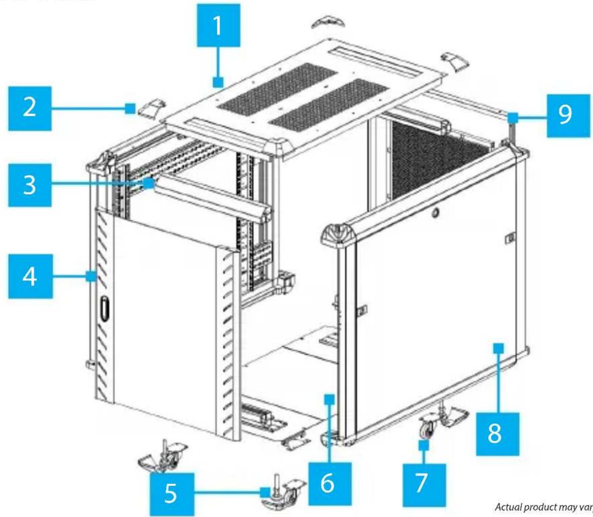
Actual product may vary from photos
| 1 | Top Panel | 6 | Bottom Panel |
| 2 | Plastic Corner Caps | 7 | Casters |
| 3 | Center Beam | 8 | Side Panel |
| 4 | Front Door | 9 | Rear Door |
| 5 | Leveling Feet | ||
To view manuals, videos, drivers, downloads, technical drawings, and more visit www.startech.com/support
Product Dimensions
Front

Actual product may vary from photos
To view manuals, videos, drivers, downloads, technical drawings, and more visit www.startech.com/support
Side
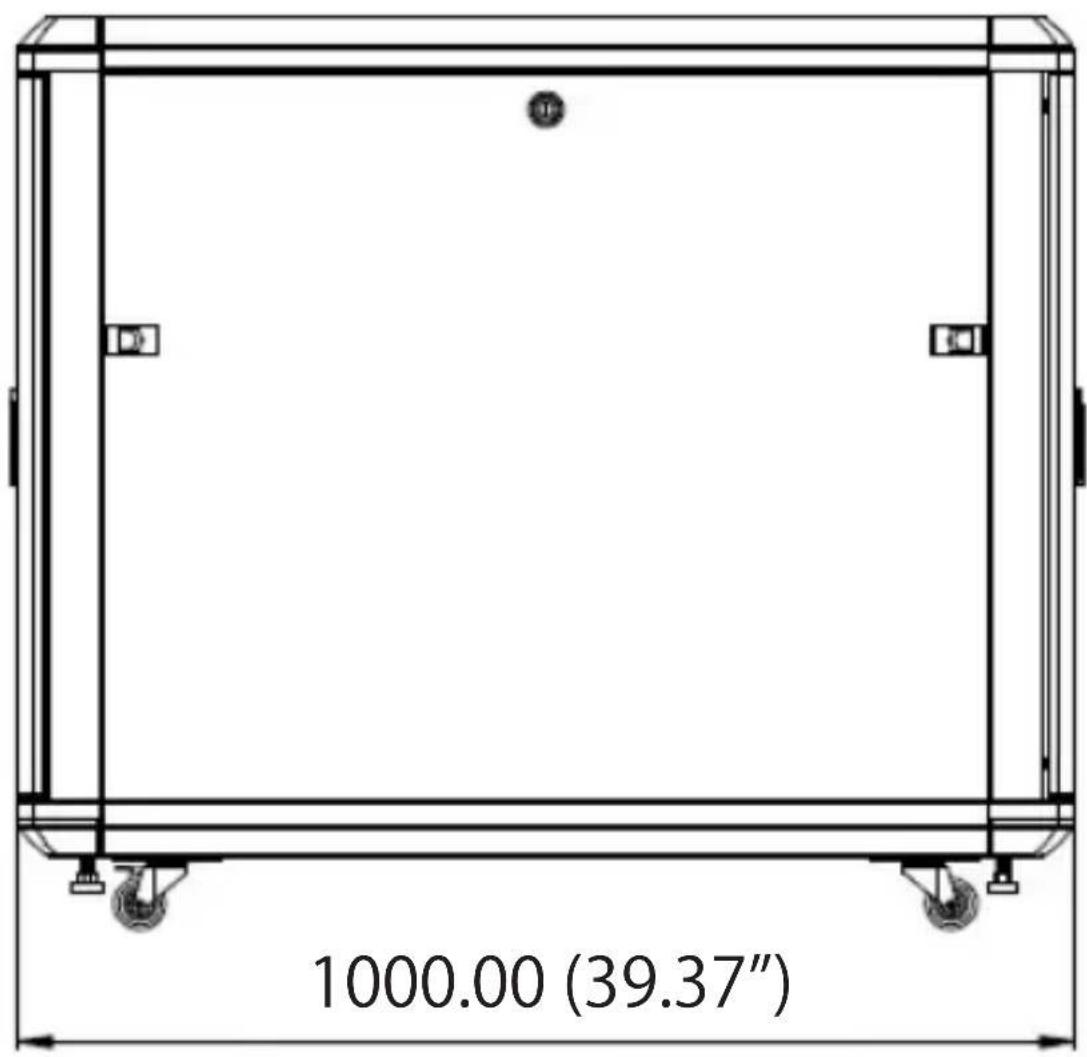
Actual product may vary from photos
To view manuals, videos, drivers, downloads, technical drawings, and more visit www.startech.com/support
Product Information
Package Contents
- Side Panels x 2
- Center Beams x 4
- Bottom Panels w/ Cable Management Slot x 2
- Bottom Panel x 1
- Front Door x 1
- Rear Door x 1
- Plastic Corner Caps x 8
• M8 x 20 mm Hex Screws x 8
• M8 Spring Washers x 8
• M4 x 10 mm Flat Head Screws x 8
• M6 x 12 mm Hex Screws x 4
• M5 x 12 mm Screws x 6 - M6 Hex Key x 1
• M8 Hex Key x 1
• M6 x 12 mm Phillips Screws x 40
• M6 Cage Nuts x 40
• M6 Plastic Cap Washers x 40 - Casters x 2
- Caster w/Brakes x 2
• M6 x 10 mm Phillips Bolts x 16 - Leveling Feet x 4
- Front/Rear Door Keys x 2
To view manuals, videos, drivers, downloads, technical drawings, and more visit www.startech.com/support
- Side Panel Keys x 2
• Phillips Head Screwdriver x 1 - Door Hinge Pin x 2
Requirements
- 14 mm Wrench x 1
• Grounding Wires x 2
• (Optional) Cage Nut Tool x 1
Assembling the Server Rack
- Align the Screw Hole located at the corner of the Side Panel with the Screw Hole at the end of a Center Beam. Ensure that the Lip on the Center Beam lines up with the Lip on the inner side of the Side Panel.
- Slide an M8 Spring Washer over a M8 x 20 mm Hex Screw.
- Insert the M8 x 20 mm Hex Screw through the Screw Hole in the Side Panel and into the Screw Hole on the Center Beam.
- Using the M8 Hex Key tighten the M8 x 20 mm Hex Screw, being careful not to over-tighten.
- Repeat steps 1 - 4 for the remaining Center Beams and to install the other Side Panel. Ensure that the Side Panels are orientated similarly.
- Orientate the Server Rack vertically so that the Caster Mounting Holes are accessible.
- Align the Mounting Holes on the Casters with the Mounting Holes at the corner of the Server Rack Frame.
- Insert four M6 x 10 mm Screws through the Mounting Holes on the Caster and into the Mounting Holes in the Server Rack Frame.
- Using a Phillips Head Screwdriver, tighten the M6 x 10 mm Screws, being careful not to over-tighten.
- Repeat steps 7 - 9 to install the other Caster and Casters with Brakes. Ensure that the set of Casters with Brakes are placed at the required end of the Server Rack Frame.
To view manuals, videos, drivers, downloads, technical drawings, and more visit www.startech.com/support
- Insert the Leveling Feet into the Pre-Threaded Holes on the bottom of the Server Rack Frame.
- Using a 14 mm Wrench, adjust the Leveling Feet so that the four Leveling Feet are all approximately the same height and are shorter than the height of the Casters.
- Align the Screw Hole in the Plastic Corner Caps (x 4) with the Screw Hole on each of the corners on the Server Rack.
- Insert a M4 x 10 mm Flat Head Screw through the Screw Holes in the Plastic Corner Cap and into the Screw Hole on the Server Rack. Using a Phillips Head Screwdriver, tighten the M4 x 10 mm Flat Head Screws, being careful not to over-tighten.
- Orient the Server Rack Frame onto the Casters.
- Repeat steps 13 - 14 to install the other four Plastic Corner Caps.
- Rest the Bottom Plate w/ Cable Management Slot at the bottom of the Server Rack Frame (at either end) and align with the Screw Holes in the frame.
- Insert two M6 x 12 mm Phillips Screws through the Screw Holes in the Bottom Plate w/ Cable Management Slot and into the Screw Holes on the interior of the Side Panel.
- Using a Phillips Head Screwdriver, tighten the M6 x 12 mm Phillips Screws, being careful not to over-tighten.
- Repeat steps 17 - 19 to install the other Bottom Plate w/ Cable Management Slot and then the Middle Bottom Plate (position accordingly).
To view manuals, videos, drivers, downloads, technical drawings, and more visit www.startech.com/support
- On the top of the Server Rack, align the Screw Holes in the four corners on the Top Panel with the Screw Holes in the four corners on the top of the Server Rack Frame.
Note: The Top Panel should fit tightly against the corner piece of the Top of the Server Rack.
-
Insert a M6 x 12 mm Hex Screw through the Screw Hole in the Top Panel and into the Screw Hole on the Server Rack Frame.
-
Using the M6 Hex Key, tighten the M6 x 12 mm Hex Screw, being careful not to over-tighten.
-
Repeat steps 22 - 23 for the remaining corners.
-
Facing the front/rear of the Server Rack Frame, insert a Door Hinge Pin into the Hinge Pin Hole located in the bottom right corner of the Server Rack Frame.
-
Angle the bottom corner of the Front Door towards the Door Hinge Pin.
-
Insert the Door Hinge Pin into the bottom Hinge Pin Hole on the Front Door. The required corner is located on the side opposite to the lock which does not have the Spring Loaded Pin.
-
In the top corner on the Front Door, pull the Spring-Loaded Hinge Pin down.
-
While holding down the Spring-Loaded Hinge Pin, angle the top corner of the Front Door towards the top corner of the Server Rack, aligning the Spring-Loaded Hinge Pin with the Hinge Pin Hole.
-
Release the Spring-Loaded Hinge Pin into the Hinge Pin Hole.
- Repeat steps 25 - 30 to install the Rear Door.
Stabilizing the Server Rack
Prior to the installation of any rack equipment, the Server Rack must be properly stabilized using the Leveling Feet which increases the size of the Base (for improved stability) and helps to prevent any Server Rack movement. The Server Rack floor should be a flat, level surface which can support the combined weight of the Server Rack and installed rack equipment.
- Using the 14 mm Wrench, lower the Leveling Feet located next to each Caster) by turning each one clockwise until the base of the Leveling Feet are tightly pressed against the surface and supporting the weight of the Server Rack.
Grounding the Enclosure
Note: This product must be grounded. Do not use this product without an earth ground connection.
- Attach Grounding Wires to the Server Rack at the labeled Grounding Studs located on the Front/Rear Doors and Side Panels.
- Route the primary Grounding Wire out from the bottom or top of the Server Rack and attach to an Earth-Ground Connection Point.
To view manuals, videos, drivers, downloads, technical drawings, and more visit www.startech.com/support
Installing Equipment
Note: When you load equipment into this product, load the heaviest equipment in the bottom units first. Continue loading equipment in a descending order of weight, so that the lighter equipment is installed in the upper sections of the enclosure and the heavier items are on the bottom.
This Server Rack comes with M6 Cage Nuts and Screws but the equipment you're installing may come with mounting hardware. Consult the documentation that came with the equipment to determine the best mounting hardware that you should use and how you should install it.
- Decide where in the Server Rack you want to install the equipment and insert the M6 Cage Nuts in the Mounting Rails.
- Line up the Mounting Holes on the equipment with the M6 Cage Nuts.
- Insert the Screws through the Mounting Holes on the equipment and into the M6 Cage Nuts.
- Using a Phillips Head Screwdriver tighten the Screws, being careful not to over-tighten.
Adjusting the Mounting Rails
- Each Mounting Rail has four M6 Screws securing the Mounting Rail to two Depth Adjustment Rails. Two M6 Screws are located at the top and two M6 Screws are located at the bottom of a Mounting Rail.
- Using a Phillips Head Screwdriver, remove the four M6 Screws and to detach the Mounting Rail.
To view manuals, videos, drivers, downloads, technical drawings, and more visit www.startech.com/support
- Remove the Cage Nuts from the Depth Adjustment Rails by pinching the two Prongs on the Cage Nut inwards.
Note: Use a Cage Nut Tool (sold separately) if you are having trouble removing the Cage Nuts from the Depth Adjustment Rails.
- Reposition the Mounting Rail along the Depth Adjustment Rails to the desired mounting depth and determine the new Cage Nut mounting locations.
Notes: The distance between each of the Mounting Rail Adjustment Hole is 7/8 inch.
- Insert the Cage Nuts into the required Square Mounting Holes on the Depth Adjustment Rails. To install, insert one side of the Cage Nut into the Square Mounting Hole and push the other side into the Square Mounting Hole, until it locks into place.
Note: Use a Cage Nut Tool (sold separately) if you are having issues installing the Cages Nuts into the Depth Adjustment Rails.
-
Reposition the Mounting Rail again along the Depth Adjustment Rails and insert the removed M6 Screws through the Mounting Rail and into the Cage Nuts in the Depth Adjustment Rails.
-
Using a Phillips Head Screwdriver to tighten the M6 Screws. Be careful not to over-tighten the M6 Screws.
Warranty Information
This product is backed by a lifetime warranty.
For further information on product warranty terms and conditions, please refer to www.startech.com/warranty.
Limitation of Liability
In no event shall the liability of StarTech.com Ltd. and StarTech.com USA LLP (or their officers, directors, employees or agents) for any damages (whether direct or indirect, special, punitive, incidental, consequential, or otherwise), loss of profits, loss of business, or any pecuniary loss, arising out of or related to the use of the product exceed the actual price paid for the product.
Some states do not allow the exclusion or limitation of incidental or consequential damages. If such laws apply, the limitations or exclusions contained in this statement may not apply to you.
Hard-to-find made easy. At StarTech.com, that isn't a slogan. It's a promise.
StarTech.com is your one-stop source for every connectivity part you need. From the latest technology to legacy products — and all the parts that bridge the old and new — we can help you find the parts that connect your solutions.
We make it easy to locate the parts, and we quickly deliver them wherever they need to go. Just talk to one of our tech advisors or visit our website. You'll be connected to the products you need in no time.
Visit www.startech.com for complete information on all StarTech.com products and to access exclusive resources and time-saving tools.
StarTech.com is an ISO 9001 Registered manufacturer of connectivity and technology parts. StarTech.com was founded in 1985 and has operations in the United States, Canada, the United Kingdom and Taiwan servicing a worldwide market.
Reviews
Share your experiences using StarTech.com products, including product applications and setup, what you love about the products, and areas for improvement.
StarTech.com Ltd.
45 Artisans Crescent
London, Ontario
N5V 5E9
Canada
StarTech.com LLP
4490 South
Hamilton Road
Groveport, Ohio
43125
U.S.A.
StarTech.com Ltd.
Unit B, Pinnacle 15
Gowerton Road
Brackmills,
Northampton
NN4 7BW
United Kingdom
StarTech.com Ltd.
Siriusdreef 17-27
2132 WT
Hoofddorp
The Netherlands
FR: fr.startech.com
DE: de.startech.com
ES: es.startech.com
NL: nl.startech.com
IT: it.startech.com
JP: jp.startech.com
- 32U Knock-Down Server Rack Cabinet with Casters | 32 in. Deep
- Use of Trademarks, Registered Trademarks, and other Protected Names and Symbols
- Warning Statements
- Varningar
- Mesures de sécurité
- Table of Contents
- Product Diagram
- Product Dimensions
- Front
- Side
- Product Information
- Package Contents
- Requirements
- Assembling the Server Rack
- Stabilizing the Server Rack
- Grounding the Enclosure
- Installing Equipment
- Adjusting the Mounting Rails
- Warranty Information
- Limitation of Liability
- Hard-to-find made easy. At StarTech.com, that isn't a slogan. It's a promise.
- Reviews
- StarTech.com Ltd.
- StarTech.com LLP
Brand : StarTech.com
Model : RK3236BKF
Category : Meuble informatique