Gravity Plus - Treadmills True - Free user manual and instructions
Find the device manual for free Gravity Plus True in PDF.


| Product Type | Treadmill |
| Brand | True |
| Model | Gravity Plus |
| Motor | 3.0 HP continuous duty |
| Speed Range | 0.5 - 12 mph (0.8 - 19.3 km/h) |
| Incline Range | 0% - 15% |
| Running Surface | 20" x 60" (51 x 152 cm) |
| Overall Dimensions | 78" L x 36" W x 58" H (198 x 91 x 147 cm) |
| Product Weight | 320 lbs (145 kg) |
| Maximum User Weight | 350 lbs (159 kg) |
| Power Requirements | 120V, 15A dedicated circuit |
| Display | 7-inch LCD with backlight |
| Programs | 20+ preset workouts including manual, interval, hill, weight loss |
| Heart Rate Monitoring | Polar chest strap compatible (included) |
| Foldable | No |
| Warranty | Lifetime frame, 5 years motor, 2 years parts and labor |
| Maintenance | Lubricate belt every 6 months; vacuum under motor cover monthly |
| Safety Features | Safety key, auto stop, emergency stop button |
| Accessories Included | Safety key, Polar chest strap, water bottle holder |
Frequently Asked Questions - Gravity Plus True
User questions about Gravity Plus True
0 question about this device. Answer the ones you know or ask your own.
Ask a new question about this device
Download the instructions for your Treadmills in PDF format for free! Find your manual Gravity Plus - True and take your electronic device back in hand. On this page are published all the documents necessary for the use of your device. Gravity Plus by True.
USER MANUAL Gravity Plus True
natural_image
Exterior view of a black treadmill with a digital display and 'TRUE' branding (no visible text or symbols on the device itself)GRAVITY PLUS TREADMILL
OWNER'S MANUAL AND ASSEMBLY GUIDE
IMPORTANT-PLEASE READ
All products shown are prototype. Actual product delivered may vary. Product specifications, features, and software are subject to change without notice.
For the most up-to-date version of this manual, please see our website: https://truefitness.com/services-support/user-manuals/
CONTACTING OUR SUPPORT TEAM
To contact TRUE for any of your pre or post installation questions, please call our toll-free numbers Monday - Friday 8:30am - 5:00pm (CST):
• Commercial Direct Customers and Corporate Accounts | 800.868.8783
• Retail Customers and Distributors | 800.883.8783
Or email us:
• Commercial Direct Customers and Corporate Accounts | service.direct@truefitness.com
• Retail Customers and Distributors | service@truefitness.com
• Service International | int.service@truefitness.com
When contacting TRUE, please have the following information ready:
- Serial Number of Unit
- Contact Information—Full Name, Email, and Phone Number
- Address of Facility or Residence
- Detailed Description Regarding Symptom of the Unit (along with pictures or video if applicable)
NOTE: Authorized service providers, dealers, and distributors may also use TRUE's online resource | portal.truefitness.com.
CONTACTING OUR SALES TEAM
Interested in owning more TRUE products? Please contact us with any product inquires so that we may direct you to the appropriate sales representative to help answer your questions.
• Phone | 800.426.6570
- Email | sales@truefi tness.com
• Hours | Monday - Friday 8:30am - 5:00pm (CST)
REPORTING FREIGHT CLAIMS OR PARTS DAMAGE
Unfortunately, sometimes materials can be damaged during shipment. If materials are damaged during shipment, please follow the guidelines below to determine the appropriate process for you to follow.
Severe Damage—Obvious damage to external packaging and internal product.
Please refuse the shipment and it will be returned to TRUE by the carrier. Contact TRUE product support by calling 800.883.8783 or sales support by calling 800.426.6570 Monday-Friday during normal business hours to notify us that the shipment has been refused. Once we have received the damaged shipment, a replacement shipment will be sent to you. If the shipment comes in multiple boxes, only refuse boxes with damage.
Slight Damage—Minimal damage to external packaging with unknown internal damage to product.
If the shipment has minimal damages and you are not sure if the actual product is damaged, you must sign the bill of lading as damaged when accepting the shipment. Once you have opened the box and you have determined something is indeed damaged, please gather the serial number, model number, description of damage, and photos of damage. Please make sure the photos include the damaged product as well as the damaged box the product arrived in. Contact TRUE product support (service@truefitness.com | 800.883.8783) or TRUE sales support (sales@truefitness.com | 800.426.6570) Monday-Friday during normal business hours.
Concealed Damage—No damage to external packaging but internal damage to product.
You may receive a shipment that looks intact and discover once the box has been opened that there are hidden damages. Please notify the carrier immediately. TRUE will not be able to file a claim if the carrier is not notified in a timely manner. Once you have called the carrier you will need to gather the serial number, model number, description of damage, and photos of damage. Contact TRUE product support (service@truefitness.com | 800.883.8783) or TRUE sales support (sales@truefitness.com | 800.426.6570) Monday-Friday during normal business hours.
TABLE OF CONTENTS
SAFETY INSTRUCTIONS
IMPORTANT SAFETY INSTRUCTIONS—SAVE THESE INSTRUCTIONS....5
POWER REQUIREMENTS....7
SPACE REQUIREMENTS....8
SPECIFICATIONS....8
WARNING DECALS....9
COMPLIANCES....9
PROPER TRAINING POSITION AND TREADMILL SAFETY....10
ASSEMBLY INSTRUCTIONS
PREASSEMBLY CHECKLIST....11
ASSEMBLY STEPS....15
PRODUCT FEATURES
BASE OVERVIEW....35
CONSOLE OVERVIEW....36
CARE AND MAINTENANCE
INSPECTION....38
CLEANING THE EQUIPMENT....38
LEVELING THE MACHINE....39
RUNNING BELT ALIGNMENT....40
TENSIONING THE RUNNING BELT....41
PREVENTATIVE MAINTENANCE....42
LONG TERM STORAGE....42
ADDITIONAL INFORMATION
TROUBLESHOOTING....43
WIRING DIAGRAMS....45
WARRANTY INFORMATION
COMMERCIAL WARRANTY 46
LIMITED-USE COMMERCIAL WARRANTY 47
IN-HOME USE WARRANTY 47
WARRANTY DETAILS 48
WARRANTY REGISTRATION 49
SAFETY INSTRUCTIONS
IMPORTANT SAFETY INSTRUCTIONS—SAVE THESE INSTRUCTIONS
This equipment is intended for a commercial or institutional setting. This owner's manual should be accessible to all personal trainers, faculty, and members.
- Read and understand all instructions and warnings prior to use.
- Obtain a medical exam before beginning any exercise program. If at any time during exercise you feel faint, dizzy, or experience pain, stop and consult your physician.
- Obtain proper instruction prior to use.
• This unit is intended for commercial use only.
• Inspect the unit for incorrect, worn, or loose components and do not use until corrected, replaced, or tightened prior to use. - Do not wear loose or dangling clothing while using the unit.
- Care should be used when mounting or dismounting the unit.
- Read, understand, and test the emergency stop procedures before use.
- Disconnect all power before servicing the unit.
- Do not exceed maximum user weight of 500 lbs / 226.7 kg.
- Keep the top side of the moving surface clean and dry.
- Keep children and animals away.
- Use caution when moving and assembling unit.
• All exercise equipment is potentially hazardous. If attention is not paid to the conditions of equipment usage, death, or serious injury could occur.
▲ DANGER: To reduce the risk of electric shock, always unplug this product when not in use, before cleaning, or attempting any maintenance activity. Do not handle the plug with wet hands.
WARNING: To reduce the risk of burns, fire, and electric shock or injury to persons, follow these instructions:
- Heart rate monitoring systems may be inaccurate. Over-exercising may result in serious injury or death. If you feel faint, dizzy, or experience pain, stop exercising immediately.
- Health related injuries may result from incorrect or excessive use of exercise equipment.
- TRUE STRONGLY recommends seeing a physician for a complete medical exam before undertaking an exercise program, particularly if the user has a family history of high blood pressure or heart disease, is over the age of 45, smokes, has high cholesterol, is obese or has not exercised regularly in the past year. Additionally, TRUE recommends consulting a fitness professional on the correct use of this product.
- Equipment should be immediately taken out of use if it fails to work properly or when a warning is presented electronically.
- When using this exercise machine, basic precautions should always be followed.
-
Use this equipment only for its intended use as described in this manual.
-
Do not move the equipment by lifting the console. Do not use the console as a handlebar during a workout.
- This product can expose you to chemicals including Toluene and Acrylamide which are known to the State of California to cause Cancer and birth defects or other reproductive harm. For more information, go to www.P65Warnings.ca.gov.
- Keep equipment stable on fl at ground.
- Risk of personal injury-crushing hazard when equipment is in operation. Keep feet, hands, and fingers away from moving parts.
- Replace warning labels that may be worn, damaged, or missing.
- Replace any non-working or damaged components, remove the unit from service until repair is performed.
- Do not operate the equipment while being covered with a blanket, pillow, plastic, or anything that insulates or stops airflow. Keep air openings free of lint, hair or any obstructing material.
- To avoid serious injury, remove and store the power cord when the machine is not in use.
- This appliance should never be left unattended when plugged in.
- Do not use any type of extension cord with this product.
- Never operate a TRUE product if it has a damaged power cord or electrical plug, or if it has been dropped, damaged, or even partially immersed in water.
- Use a TRUE AC power cord or AC/DC adapter only.
-
Position this product so the power cord plug is accessible to the user.
-
Keep the power cord away from heated surfaces. Do not pull the equipment by the power cord or use the cord as a handle. Do not run the power cord along the side or under the equipment.
- If the electrical supply cord is damaged it must be replaced by the manufacturer, an authorized service agent, or a similarly qualified person to avoid a hazard.
- This product must be connected to a properly grounded electrical outlet.
- To disconnect, turn power OFF at the ON/OFF switch if applicable, then remove plug from electrical outlet. On the machine power switch, ( ) means that the machine power is ON and ( ) means the machine power is OFF.
- Never insert objects into any openings in this product. If an object should drop inside, turn off the power, unplug the power cord from the outlet and carefully retrieve it. If the item cannot be reached, contact TRUE product support.
- Any changes or modifications to this equipment could void the product warranty.
- Do not use this product in areas where aerosol spray products are being used or where oxygen is being administered. Such substances create the danger of combustion and explosion.
- Do not use this product outdoors, near water, while wet, or in areas of high humidity including extreme temperature changes.
- Close supervision is necessary when used near children under the age of 15, or disabled persons.
- This equipment is not intended for use by persons with reduced physical, sensory, or mental capabilities, or lack of experience and knowledge, unless they are supervised or have been given instruction concerning use of the equipment by a person responsible for their safety.
- Children shall not play with the appliance.
- Cleaning and user maintenance shall not be made by children without supervision.
- Wear shoes with rubber or high traction soles. Do not use shoes with heels, leather soles, cleats or spikes. Make sure no stones are embedded in the soles. Do not use this product in bare feet. Keep all loose clothing, shoelaces and towels away from moving parts.
- Do not use if you have a cold or fever.
- To avoid injury, attach the safety clip to clothing before use.
- When mounting the treadmill, ensure the treadmill belt is not running.
- Use handlebars to maintain balance when mounting and dismounting the treadmill and for additional stability while exercising.
• To avoid injury, stand on the side rails before starting the equipment. - While the treadmill is in use, proceed at a speed that the user can safely maintain with the ability to immediately engage the safety key to stop the treadmill belt if necessary.
-
Avoid the possibility of bystanders being struck or caught between moving parts by making sure that they are out of reach of the equipment while it is in motion.
-
Do not use typing or web surfing features at excessive speeds. Always stabilize yourself when using typing or web surfing features. (Varies by console option.)
- Never place liquids of any type directly on the unit except in the accessory tray or bottle holders. Containers with lids are recommended.
• Always follow the console instructions for proper operation. - Do not use the contact heart rate grips as a handlebar during a workout.
- Avoid exiting equipment while leaving the tread belt in motion.
- Never walk or jog backwards on the equipment.
- Allow only one person at a time on the equipment while it's operating.
- Do not allow animals on or near the equipment while in operation.
• To avoid serious injury, do not touch the incline rack while the equipment is in use. - To avoid serious injury, do not touch the belt while the equipment is in use.
- Do not reach into or underneath the unit, or tip it on its side during operation.
- Do not change the incline of the equipment by placing objects under it.
- Do not use attachments not recommended by the manufacturer.
- Allow only trained personnel to service this equipment.
- It is the sole responsibility of the owner/operator to ensure regular and scheduled maintenance is performed.
- Do not remove the motor cover or you may risk injury due to electric shock.
Please contact TRUE product support if the motor area needs servicing. - Noise emission under load is higher than without load. A-weighted emission sound pressure level at the trainer's ear: 67 dBA.
POWER REQUIREMENTS
Read and understand all instructions before plugging any TRUE power cord into an electrical outlet.
DEDICATED LINE
This product requires a dedicated line without GFCI (Ground-Fault Circuit Interrupter) or AFCI (Arc-Fault Circuit Interrupter). GFCI and AFCI protection is not required for receptacles on a dedicated branch circuit located and identified for a cord-and-plug-connected appliance, such as a treadmill. A dedicated line assures that adequate power is available for safe operation over the life of your TRUE product.
GROUNDING INSTRUCTIONS
This product must be grounded. If the product malfunctions or breakdowns, grounding provides a path of least resistance for electric current to reduce the risk of electric shock. This product is equipped with a cord having an equipment grounding conductor and a grounding plug. The plug must be plugged into an appropriate outlet that is properly installed and grounded in accordance with all local codes and ordinances.
! DANGER:
- Improper connection of the equipment grounding conductor can result in risk of electrical shock.
- Check with a qualified electrician or service provider if you are in doubt as to whether the equipment is properly grounded or installed on a dedicated line.
-
Seek a qualified electrician to perform any modifications to the cord or plug. TRUE is not responsible for injuries or damages as a result of cord or plug modification.
-
To reduce the risk of burns, fire, electric shock, or injury, it is imperative to connect each product to a properly grounded 110V or 220V electrical outlet. The voltage required for your unit is located on the serial number decal (usually on the front of the unit). Depending on where you live voltage requirements differ.
- Some TRUE products require a circuit rated 110V, 60 Hz, and 20 amps. In the United States, most residential homes have circuits rated 110V, 60 Hz, and 15 amps. If your unit requires a 20 amp outlet, contact an electrician to install a dedicated 20 amp circuit prior to use.
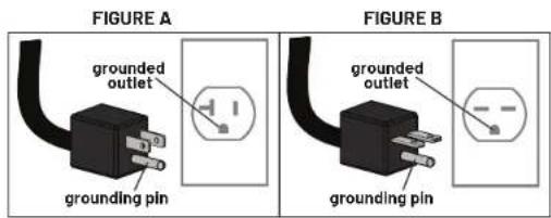
- 110 Volt—This model is for use on a nominal 110V circuit and has a grounding plug that looks like the plug illustrated in figure A. Make sure the product is connected to an outlet having the same configuration as the plug. No adapter should be used with this product.
- 220 Volt—This model is for use on a circuit having a nominal rating no less than 208V and more than 240V and is factory equipped with a specific electric cord and has a grounding plug that looks like the plug illustrated in figure B. Make sure that the product is connected to an outlet having the same configuration as the plug in figure B. No adapter should be used with this product. If the product must be reconnected for use on a different type of electric circuit, the reconnection should be made by qualified service personnel.
| Power Information | ||||||
| Model | Line Voltage (V) | Frequency (Hz) | Rated Current (Amps) | Number of Units per Circuit | Plug/Outlet* | Max Power Dissipation (Watt) |
| TC2-0A-35 | 110 50/60Hz 20 | Dedicated 1 | NEMA 5-20 | 1650 | ||
| 220 50/60Hz 8 | Dedicated 1 | NEMA 6-15* | 1650 | |||
*The plug configuration for the power adapter may vary by country.
SPACE REQUIREMENTS
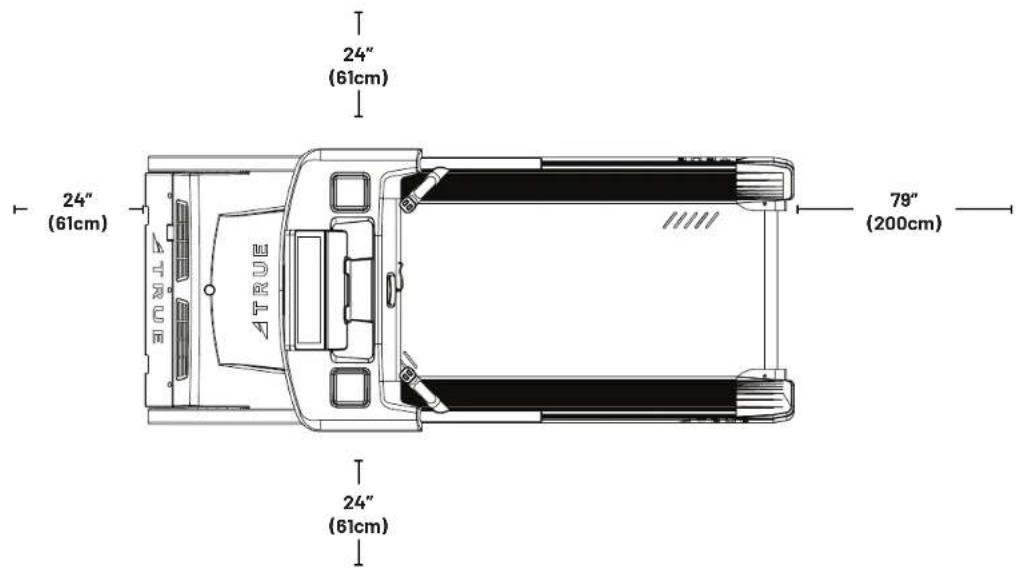
TRUE recommends leaving a minimum of 24" (61cm) on each side of the equipment and a 79" (200cm) safety zone at the rear of the equipment.
SPECIFICATIONS
• DIMENSIONS (L X W X H)
83" x 36" x 68" / 211cm x 91cm x 168cm
- MACHINE WEIGHT
349 lbs / 158 kg
• MAXIMUM USER WEIGHT
500 lbs / 226.7 kg
WARNING DECALS
WARNING: Replace warning labels that may be worn, damaged, or missing.
To replace any worn or missing decals contact TRUE product support (service@truefitness.com | 800.883.8783).

COMPLIANCES
This equipment complies with all applicable codes and regulations. For a complete list of compliances, please visit www.truefitness.com.
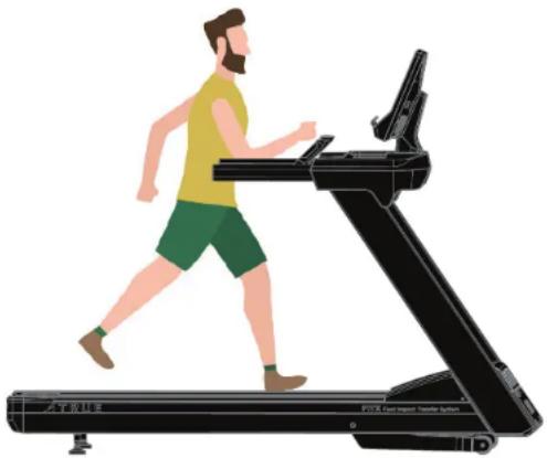
PROPER TRAINING POSITION AND TREADMILL SAFETY
Treadmill Entry
When first stepping on the treadmill, step onto the side rails (straddle covers) and hold the hand rails until both feet are fully on the belt.
Treadmill Use
Ensure you have good balance and your feet are stable before you start the treadmill.
Keep your gaze forward and avoid looking down or to your sides, this will help maintain good balance and prevent falls.
While using, ensure all hands, legs, and feet remain within the boundary box of the treadmill belt.
Treadmill Exit
When getting off the treadmill, wait until the belt comes to a full stop, then step on the side rails (straddle covers) and then onto the floor.
natural_image
Illustration of a person running on a treadmill with a camera, no text or symbols presentASSEMBLY INSTRUCTIONS

NOTE: Supplemental video available @TRUEFitnessservicevids: https://www.youtube.com/playlist?list=PLr3lgv32UrupdGovHVj-zecgk9kvFdC2h
PREASSEMBLY CHECKLIST
BASIC GUIDELINES FOR SETTING UP THE EQUIPMENT
After removing the equipment from the packaging, place the equipment on a clean, level surface. Make sure the electrical cord easily reaches a grounded three-pronged outlet.
▲DANGER: Do not use an extension cord or ungrounded outlet. The ground helps prevent electrical damage to your equipment and enhances your safety by helping to prevent shock. Check with a qualified electrician or serviceman if you are in doubt as to whether the equipment is properly grounded. Do not modify the plug provided with the unit if it will not fit the outlet. Have a proper outlet installed by a qualified electrician.
CAUTION:
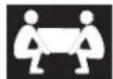
Use caution when assembling the equipment.
Unpacking and assembling of this product is a two person task.

Use caution when unpacking this product. Avoid damage to the product.
DO NOT use a box cutter. DO NOT slice into the packaging.
VERIFY BOX CONTENTS
IMPORTANT! Please verify box contents. If you have questions, or if there are any missing parts, contact product support (service@truefitness.com | 800.883.8783).
ASSEMBLY INSTRUCTIONS CONTINUED
| TOOLS NEEDED FOR ASSEMBLY INCLUDED IN BOX | ||
| 5mm Allen Wrench NO | Dramed | |
| 6mm Allen Wrench NO | Screwed | |
| 8mm T-Handle Allen Wrench NO | Screwed | |
| 7/16" Ratchet NO | Screwed | |
| 13mm Wrench NO | Drewed | |
| TOOLS NEEDED FOR ASSEMBLY INCLUDED IN BOX | ||
| 15/16" Wrench NO |  | |
| ☐ | ||
| 7/8" Wrench NO | [GT79] | |
| #2 Phillips Screwdriver NO | [84CB] | |
| ☐ | ||
| Wire Cutters NO | [CC07] | |
| ☐ | ||
| Level NO | [Z005] | |
| Long-Length Ruler 0"-48"/0 cm-120 cm | NO | |
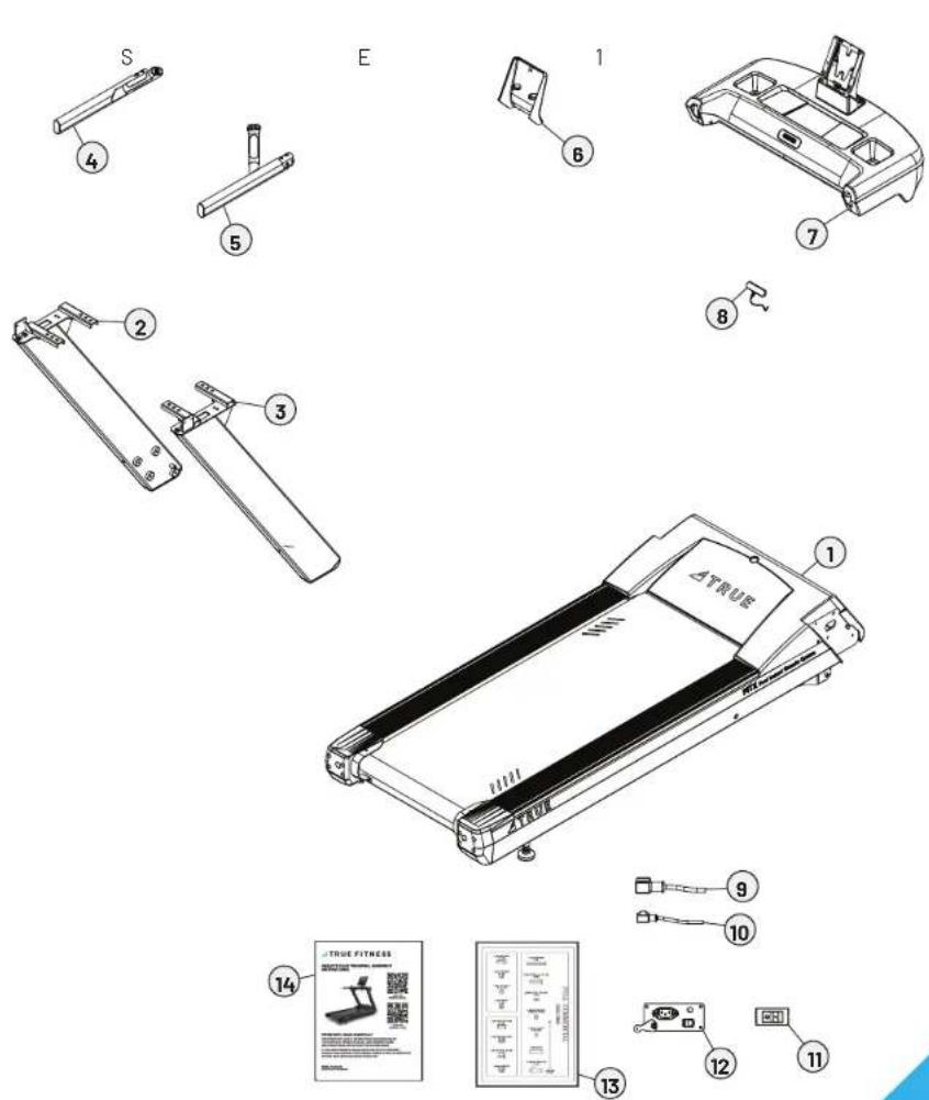
BOX CONTENTS
| ITEM DESCRIPTION QTY | ||
| 1 | B | A |
| 2 LEFT PEDESTAL 1 | ||
| 3 RIGHT PEDESTAL 1 | ||
| 4 LEFT HEART RATE HANDLEBAR 1 | ||
| 5 RIGHT HEART RATE HANDLEBAR 1 | ||
| 6 CONSOLE REAR COVER 1 | ||
| 7 CONSOLE RACK 1 | ||
| 8 | SAFETY KEY | 1 |
| 9 110V POWER CORD 1 | ||
| 10* | 220V POWER CORD* | 1 |
| 11* | 220V SWITCH ASSEMBLY* | 1 |
| 12* 220V POWER INLET ASSEMBLY* 1 | ||
| 13 HARDWARE PACK 1 | ||
| 14 | MANUAL | 1 |
*The 220V Power Cord, 220V Power Inlet Assembly, and 220V Switch Assembly are only included with this product if the unit is being used on a circuit having a nominal rating of more than 120-V.
© 2024 TRUE Fitness All Rights Reserved.
HARDWARE PACK CONTENTS
TC10209 Hardware Pack
| TC2-0A-35 HARDWARE PACK | ||
| ITEM DESCRIPTION QTY | ||
| PS0099 | LOCK WASHER M8, BLK ZP | 22 |
| PS0100 | SCREW, SHCS M8-1.25X25, BLK ZP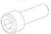 | 18 |
| TPS8123 | SEMS PAN HEAD BOLT, MAXP1 25X90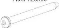 | 4 |
| TC10124 | SCREW, BHCS, M8-1.25X55, BLK 7P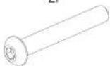 | 4 |
| TCS0024 | SCREW, SEMS, M4-0.7X12MM, NYLOK, BLK | 18 |
| TI0076 | TRUSS PHILLIPS BOLTM4XP0.7X12 | 2 |
| TC2-0A-35 HARDWARE PACK | ||
| ITEM DESCRIPTION QTY | ||
| VC90141 | LOCK NUT, M8-1.25, 8T, BLK, ZP | 4 |
| EST0019 | CAP, MOTOR COVER | 1 |
| ST1024 | SUBASSEMBLY, SAFETY KEY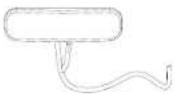 | 1 |
| TCS0028 | CORD LOCK, SAFETY KEY | 1 |
ASSEMBLY STEPS
Step 1—Remove Motor Cover Plastics
| Tools Used in this Step | |
| #2 Phillips Screwdriver |  |
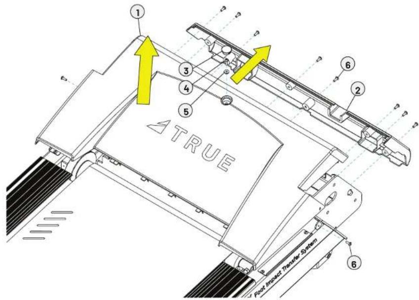
Using a #2 Phillips screwdriver remove and set aside the top and bottom motor cover plastics using 11 screws, 1 flat washer, and 1 motor cap cover.
| Parts Used in this Step | |||
| Item P | Part Description | Qty | |
| 1 | TC10068 COVER, MOTOR TOP ASSEMBLY 1 | ||
| 2 | TC10069 COVER, MOTOR BOTTOM 1 | ||
| 3 | EST0019 CAP, MOTOR COVER 1 | ||
| 4 | TC0056 BOLT M5XP0.8X20 1 | ||
| 5 | TC10121 WASHER, M5, ID5 X OD15 X 2, BLK ZP 1 | ||
| 6 | TC10120 SCREW, PHMS, M5-0.8X15, BLK ZP 10 | ||
© 2024 TRUE Fitness All Rights Reserved.
Step 2—Attach Pedestals
| Tools Used in this Step | |
| 6mm Allen Wrench |  |
| Wire Cutters |  |
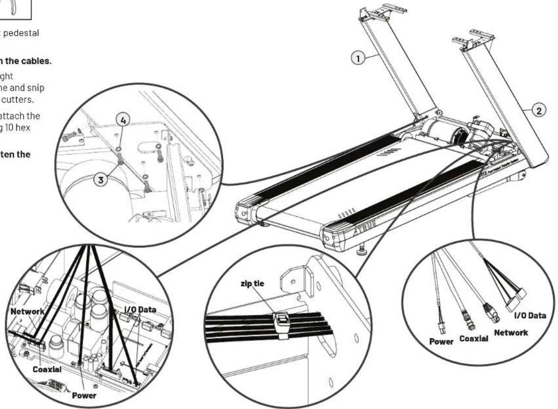
A. Route and connect the right pedestal cables to the lower board.
IMPORTANT! DO NOT pinch the cables.
B. Using a zip tie, secure the right pedestal cables to the frame and snip excess material using wire cutters.
C. Using a 6mm allen wrench, attach the pedestals to the base using 10 hex screws, but do not tighten.
IMPORTANT! DO NOT fully tighten the hardware until step 4.
| Parts Used in this Step | |||
| Item P | Part Description | on Qty | |
| 1 TC | 0009 ASSEMBLY, PEDESTAL, LH 1 | ||
| 2 TC | 0010 ASSEMBLY, PEDESTAL, RH 1 | ||
| 3 PS | 0100 SCREW, SHCS M8-1.25X25, BLK ZP 10 | ||
| 4 PS | 0099 LOCK WASHER M8, BLK ZP 10 | ||
© 2024 TRUE Fitness All Rights Reserved.
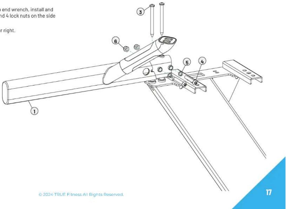
Step 3—Attach Heart Rates Handlebars
| Tools Used in this Step | |
| 5mm Allen Wrench |  |
| 13mm Wrench |  |
| Parts Used in this Step | |||
| Item Part Description Qty | |||
| 1 | TC10260 ASSEMBLY, HANDRAIL, LH 1 | ||
| 2 | TC10261 ASSEMBLY, HANDRAIL, RH 1 | ||
| 3 | TPS8123 SEMSPAN HEAD BOLT, M8XP1.25X90 4 | ||
| 4 | TC10124 SCREW, BHCS, M8-1.25X55, BLK ZP 4 | ||
| 5 | PS0099 LOCK WASHER M8, BLK ZP 4 | ||
| 6 | VC90141 | LOCK NUT, M8-1.25, 8T, BLK, ZP | 4 |
A. Using a 5mm allen wrench, install and tighten the 4 hex screws on the top of the heart rate handlebars
B. Using a 5mm allen wrench and a 13mm open end wrench, install and tighten the 4 hex screws, 4 lock washers, and 4 lock nuts on the side of the heart rate handlebars.
NOTE: Handlebars are marked L for left and R for right.
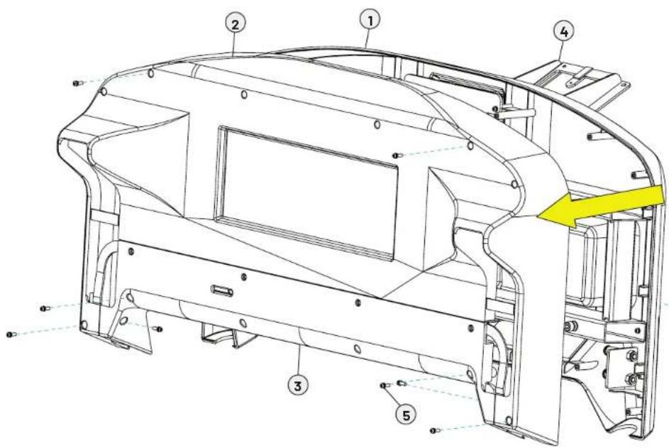
Step 4—Attach Console Rack
| Tools Used in this Step | |
| 6mm Allen Wrench | [DTK2] |
| #2 Phillips Screwdriver | [DTTH] |
| Parts Used in this Step | |||
| Item | Part Description | Qty | |
| 1 TO | 10073 SUBASSE | MBLY, SHROUD, TOP | 1 |
| 2 TO | 10074 SHROUD | BOTTOM FRONT | 1 |
| 3 TO | 10075 SHROUD | BOTTOM REAR | 1 |
| 4 ST | 1033-35 ASSEMBLY, CONSOLE MAST | 1 | |
| 5 TO | S0024 | SCREW, SEMS, M4-0.7X12MM,NYI QK, BL K | 8 |
| 6 PS | 0100 SCREW, SHCS M8-1.25X25, BLK ZP | 8 | |
| 7 PS | 0099 LOCK WASHER M8, BLK ZP | 8 | |
A. Using a #2 Phillips screwdriver, remove and set aside the lower console rack covers using 8 screws.
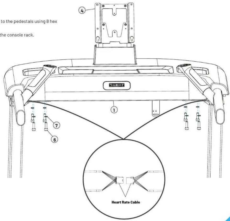
Step 4-Attach Console Rack Continued
B. Align the console rack with the holes on the pedestals and place the console rack on the pedestals.
C. Connect the heart rate cables.
IMPORTANT! DO NOT pinch the cables.
D. Using a 6mm allen wrench, attach the console rack to the pedestals using 8 hex screws and 8 lock washers.
NOTE: Remove the protective film after installing the console rack.
E. Fully tighten the pedestal hardware.
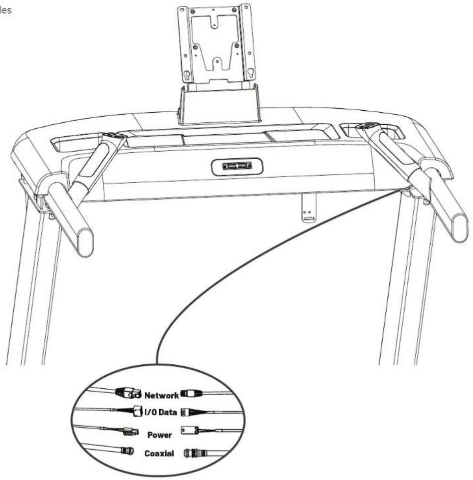
Step 5—Connect Console Rack Cables
Connect the power, coaxial, network, and I/O data cables between the right pedestal and console rack.
IMPORTANT! DO NOT pinch the cables.
© 2024 TRUE Fitness All Rights Reserved.
Optional Step 6—Attach Decline Foot Assembly
| Tools Used in this Step | |
| 7/8" Wrench |  |
| 15/16" Wrench |  |
| 7/16" Ratchet |  |
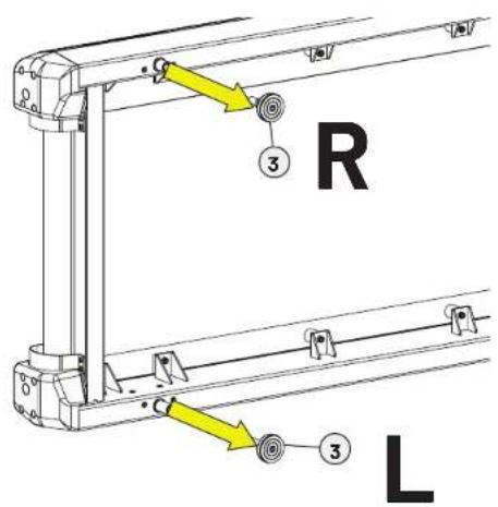
A. Using 2 people, place protective padding on the floor and carefully tilt the treadmill on its side.
B. Using a 7/8" open end wrench, loosen the left leveling foot and remove it from the treadmill frame.
C. Using a 15/16" wrench, loosen the jam nut on the right leveling foot and remove it from the treadmill frame.
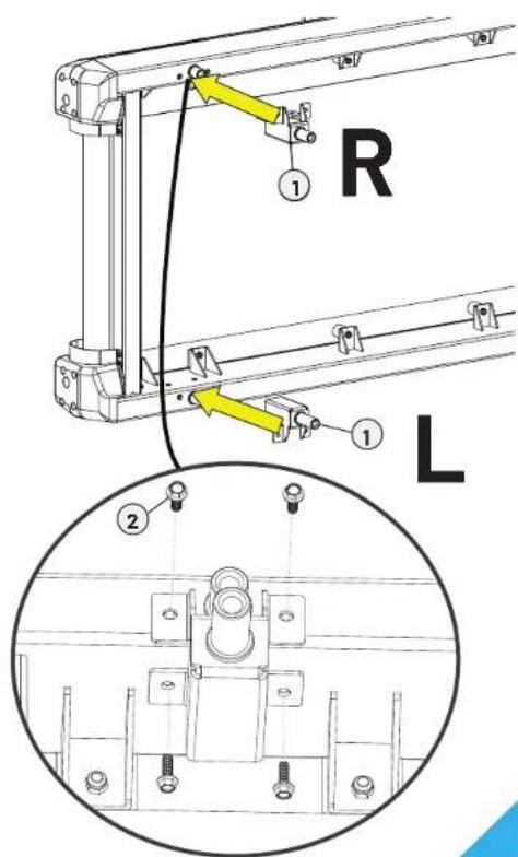
D. Using a 7/16" ratchet, attach the decline brackets to the treadmill frame using 8 bolts.
NOTE: The longer decline bracket goes on the left.
| Parts Used in this Step | ||
| Item Part Description Qty | ||
| 1 TC 0220 SUBASSEMBLY, DECLINE FEET 1 | ||
| 2 TCS0027 BOLT-HEX HEAD 1/4" -20UNC X 20MM 8 | ||
| 3 C461100 | SUBASSEMBLY, LEVELING FOOT, 2-1/2"D W/JAM NUT | 2 |
© 2024 TRUE Fitness All Rights Reserved.
Optional Step 6—Attach Decline Foot Assembly Continued
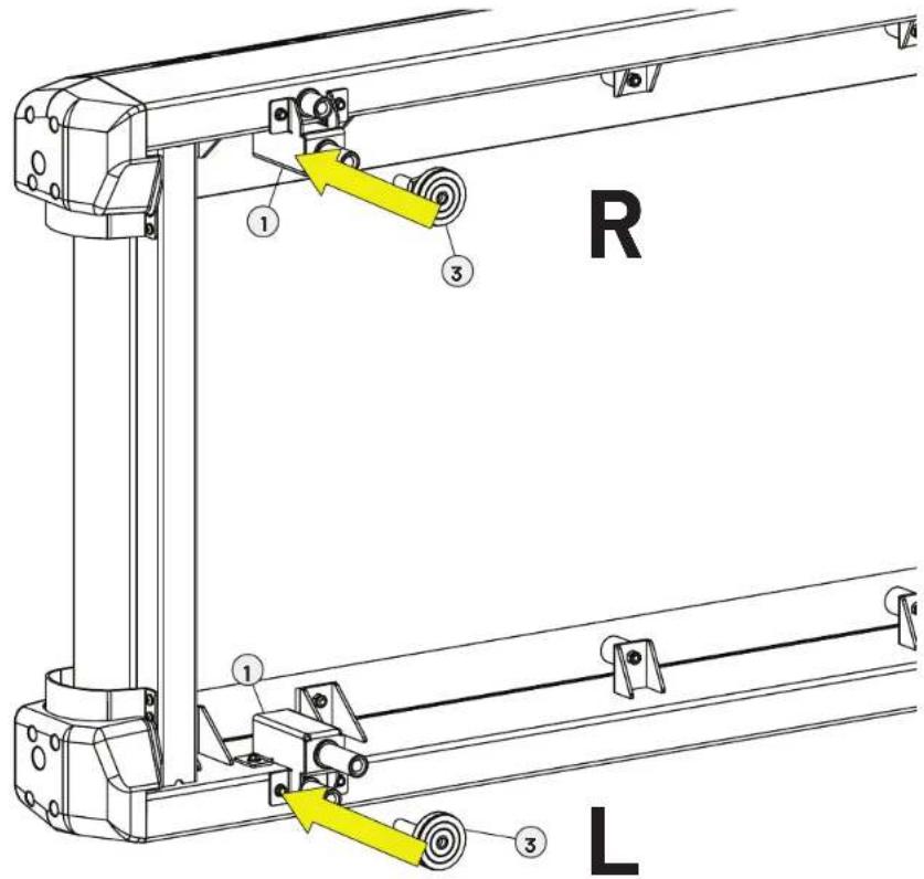
E. Insert the leveling feet into the decline assembly holes, tighten using a 7/8" open end wrench.
F. Return the treadmill to the upright position.
- If the treadmill is not level, adjust the right leveling foot with a 7/8" open end wrench before tightening the jam nut with a 15/16" open end wrench.
NOTE: Enable decline functionality on the console, these instructions are included in the console owner's manual. If the optional decline kit is installed, select YES, DECLINE to enable decline functionality. A power cycle will be required to complete the process.
© 2024 TRUE Fitness All Rights Reserved.
Step 7-Attach Console
| Tools Used in this Step | |
| #2 Phillips Screwdriver |  |
| Parts Used in this Step | |||
| Item Part Description on Qty | |||
| 1N/A CONSOLE 1 | |||
| 2 ST1033-35 ASSEMBLY, CONSOLE MAST 2 | |||
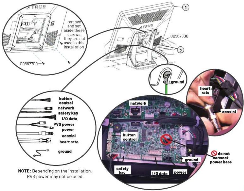
A. If the console has three screws (00567700 // SCREW, M4-.7 X 12 PPHMS SEMS) preassembled, remove and set aside these screws. They are not used in the installation. Remove and set aside the top two screws (00567800 // SCREW, M5-.8X12 COMBO PHILLIPS/ COMMON TRUSS HEAD - ACG BLACK) preassembled to the console. Slightly loosen the bottom two screw but leave them installed. All four screws will be used to secure the console to the mast in step C.
B. Connect the console and base cables: network, coaxial, heart rate, safety key, button control, I/O data, power, and ground (use the screw on the console mast to attach the ground cable from the console).
NOTE: The LED console does not use the coaxial or network cables. Those cables can be tucked back down the console mast.
Ensure all cables are routed inside the console mast to avoid pinching cables.
C. Using a #2 Phillips screwdriver, secure the console to the console mast using the four screws (00567800).
Optional Step 8—Install 220V Power Inlet Assembly
| Tools Used in this Step | |
| #2 Phillips Screwdriver |  |
NOTE: This step is only for units that will be used on a circuit having a nominal rating of more than 120-V.
A. Using a #2 Phillips screwdriver, remove the 110V power inlet assembly and 110V switch assembly.
B. Disconnect the wires from the 110V power inlet and switch assemblies and transfer them to the 220V power inlet and switch assemblies.
IMPORTANT! The 220V panel has a green, blue, and brown dot. The dot color corresponds to the cable color.
- Move the green/yellow cable to the green dot.
- Move the blue cable to the blue dot.
- Move the brown cable to the brown dot.
NOTE: Make sure the colored cables are across from each other.
C. Using a #2 Phillips screwdriver, secure the 220V power inlet assembly and 220V switch assembly to the frame.
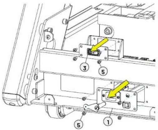
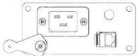
110V Power Inlet Assembly
| Parts Used in this Step | |||
| Item | Part Description | Qty | |
| 1 TC10090 ASSEMBLY, POWER PLATE, 110V 1 | |||
| 2 TC10091 ASSEMBLY, POWER PLATE, 220V 1 | |||
| 3 TC10221 SUBASSEMBLY, POWER SWITCH, 110V 1 | |||
| 4 TC10222 SUBASSEMBLY, POWER SWITCH, 220V 1 | |||
| 5 T10011 | SQREW, PHMS, M5-0.8X10, BLK ZP | B | |
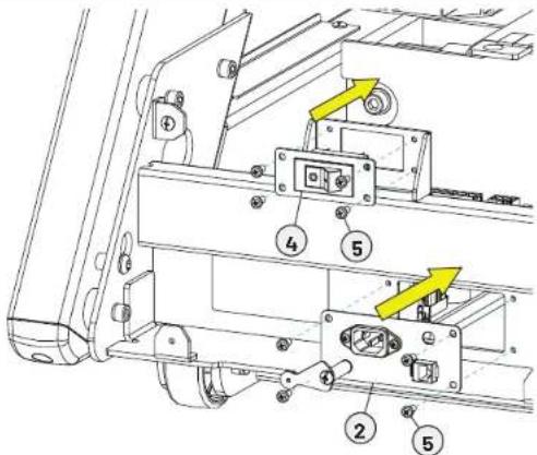
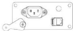
220V Power Inlet Assembly
Step 9—Attach Power Cord
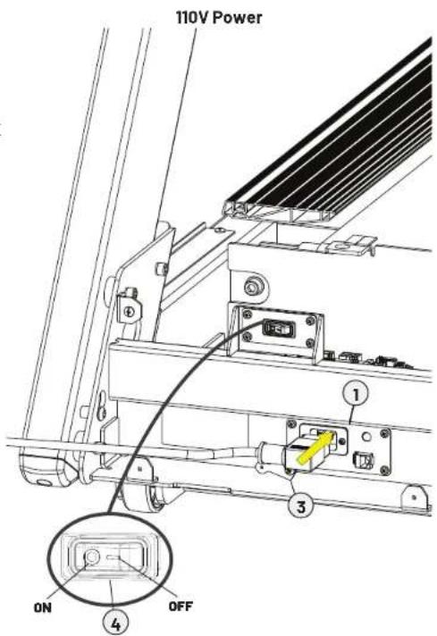
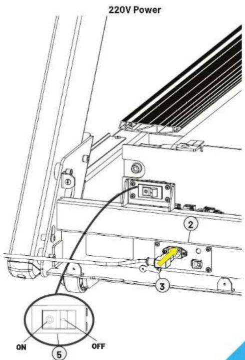
A. Insert the appropriate power cord into the corresponding power inlet.
B. Secure the power cord in place using the power cord retainer.
NOTE: In the event the current drawn by the treadmill exceeds a specified value, the circuit breaker portion of the power ON/OFF switch will trip. The rocker lever will automatically release and position itself to a position half way between ON and OFF, thus opening the power circuit. If this should occur, please wait 10 minutes and then reset the circuit breaker by rocking the power switch fully to the OFF position (☐), and then rocking the power switch back to the ON position
(●)If it does not reset, or the circuit breaker operates again under normal use, contact TRUE Product Support at 800.883.8783 or service@truefi.tness.com.
| Parts Used in this Step | |||
| Item Part Description Qty | |||
| 1 TC10090 | ASSEMBLY, POWER PLATE, 110V | 1 | |
| 2 TC10091 | ASSEMBLY, POWER PLATE, 220V | 1 | |
| 3 TI0117-35 PLATE, CORD RETAINER 1 | |||
| 4 TC10221 | SUBASSEMBLY, POWER SWITCH, 110V | 1 | |
| 5 TC10222 | SUBASSEMBLY, POWER SWITCH, 220V | 1 | |
© 2024 TRUE Fitness All Rights Reserved.
IMPORTANT STEP—DO NOT SKIP!
Step 10—Configure the Console with the Base and Run Calibration\*
Please follow the instructions included with your console for important configuration and calibration steps.
Please contact product support right away if you run into issues setting up the machine:
800.883.8783 | service@truefitness.com | Monday-Friday 8:30am-5:00pm (CST)
*NOTE: All new products require configuration. However, not all new products require calibration. Refer to the table below. If calibration is required, you must calibrate the machine.
| PRODUCT CALIBRATION REQUIREMENTS | ||
| REQUIRES CALIBRATION DOES NOT | REQUIRE CALIBRATION | |
| APEX TREADMILL APEX ELLIPTICAL | GRAVITY CROSSTRAINER | |
| GRAVITY TREADMILL PLUS APEX CRO | ROSSTRAINER GRAVITY RECUMBENT | ELLIPTICAL |
| GRAVITY TREADMILL APEX RECUMBENT BIKE LAUNCH ELLIPTICAL | ||
| LAUNCH TREADMILL DC APEX UPRIGHT BIKE LAUNCH RECUMBENT BIKE | ||
| VAPOR STRYKER APEX RECUMBENT | ELLIPTICAL LAUNCH UPRIGHT BIKE | |
| VAPOR ALPINE RUNNER | GRAVITY ELLIPTICAL | VAPOR PALISADE |
| VAPOR SPECTRUM | GRAVITY RECUMBENT BIKE | VAPOR XT-ONE |
| GRAVITY UPRIGHT BIKE | VAPOR LATERAL X | |
Step 11-Reattach Motor Cover Plastics
| Tools Used in this Step | |
| #2 Phillips Screwdriver |  |
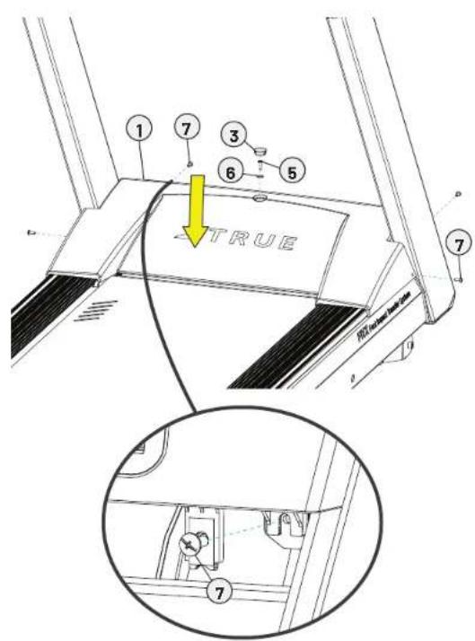
A. Using a #2 Phillips screwdriver reattach the top motor cover plastic using 5 screws, 1 fl at washer, and 1 motor cap cover.
B. Route the power cord through the hole in the bottom motor cover plastic and plug it into the corresponding outlet.
NOTE: Secure any excess cord length using the cord management bracket.
C. Insert the coaxial and ethernet cables into the power inlet and route the cables through the hole in the bottom motor cover plastic. Plug the coaxial and ethernet cables into the corresponding outlets.
© 2024 TRUE Fitness All Rights Reserved.
| Parts Used in this Step | |||
| Item | Part Description | Qty | |
| 1 TC | 0068 | COVER, MOTOR TOP ASSEMBLY | 1 |
| 2 TC | 0069 COVER, MOTOR BOTTOM 1 | ||
| 3 ES | 10019 CAP, MOTOR COVER 1 | ||
| 4 TC | 0026 BRAC KET, CORD WINDER 1 | ||
| 5 TC | 0056 BOLT M5XP0.8X20 | 1 | |
| 6 TC | 0121 | WASHER, M5, ID5 X OD15 X 2, BLK ZP | 1 |
| 7 TC | 0120 | SCREW, PHMS, M5-0.8X15, BLK ZP | 10 |
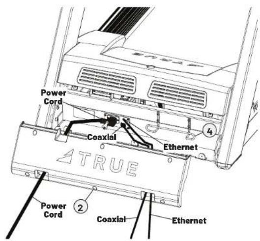
Step 11—Reattach Motor Cover Plastics Continued
D. Using a #2 Phillips screwdriver, reattach the bottom motor cover plastic using 6 screws.
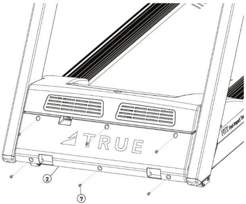
Step 12—Reattach Lower Console Rack Covers
| Tools Used in this Step | |
| #2 Phillips Screwdriver |  |
| Parts Used in this Step | |||
| Item Part Description Qty | |||
| 1 TO 10074 SHROUD, BOTTOM FRONT 1 | |||
| 2 TO 10075 SHROUD, BOTTOM REAR 1 | |||
| 3 TCS0024 | SCREW, SEMS, M4-0.7X12MM, NYLOK, BLK | 18 | |
A. Tuck excess cable length into the console rack.
IMPORTANT! DO NOT pinch the cables.
B. Using a #2 Phillips screwdriver, reattach the lower console rack covers using 18 screws.
NOTE: Be sure to use a hand screwdriver on the back corners of the lower rack console covers.
NOTE: Do not fully tighten until all screws are installed.
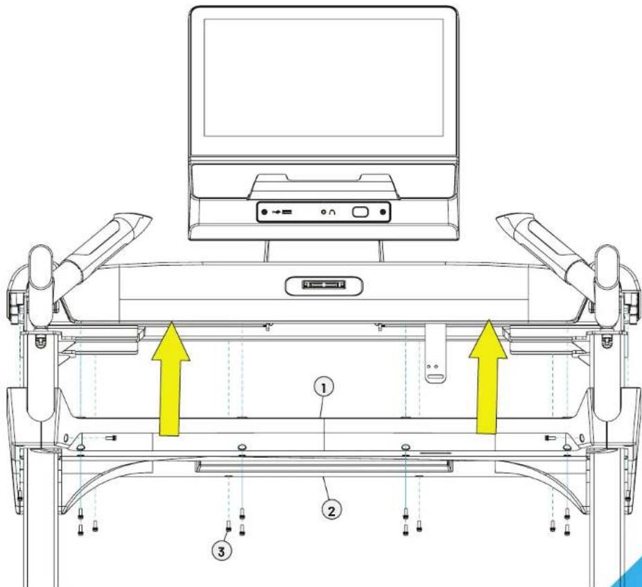
© 2024 TRUE Fitness All Rights Reserved.
Step 13—Attach Safety Key
| Parts Used in this Step | |||
| Item | Part Description | Qty | |
| 1ST | 024 SUBASSE | MBLY, SAFETY KEY 1 | |
| 2 TCS | 0028 CORD LOCK, SAFETY KEY 1 | ||
A. Insert the safety key cord through the holes on the metal tab.
B. Attach the cord lock to the end of the safety key cord and pull the cord lock up behind the metal tab.
C. Attach the safety key clip to the metal tab.
D. Remove protective film from safety key attachment point on the console rack.
E. Attach the safety key to the console rack.
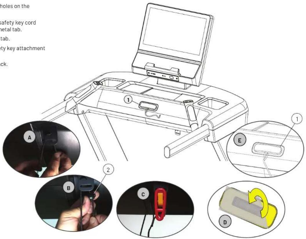
© 2024 TRUE Fitness All Rights Reserved.
Step 14—Attach Rear Console Cover
| Tools Used in this Step | |
| #2 Phillips Screwdriver |  |
Using a #2 Phillips screwdriver, secure the rear console cover to the console mast using 2 screws.
| Parts Used in this Step | |||
| Item Part Description on Qty | |||
| 1 T010076 COVER, CONSOLE BACK 1 | |||
| 2 T10076 TRUSS PHILLIPS BOLT M4XP0.7X12 2 | |||
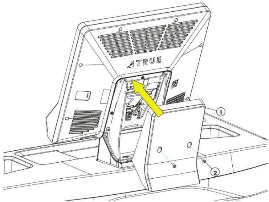
Step 15-Level the Machine
| Tools Used in this Step | |
| 7/8" Wrench |  |
Once the machine has been moved to it's designated location:
A. Verify the treadmill is resting on the floor and not on any packaging materials.
B. Using a 7/8" open end wrench, adjust the back right leveling foot until it contacts the floor.
IMPORTANT! Do not adjust the leveling foot to such a height that it detaches or unscrews from the machine.
C. Verify the lock nut is securely tightened and flush against the bottom of the frame.
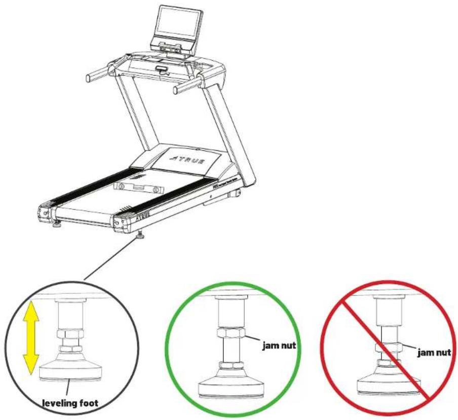
© 2024 TRUE Fitness All Rights Reserved.
Step 16-Break in Belt and Deck
Your treadmill uses a high-efficient, low-friction, hard waxed deck and maintenance free belt. For optimal performance, TRUE recommends a 15 minute break in period to help transfer the wax from the deck to the belt. On a brand new unit, ensuring the wax has been adequately worked into the belt helps alleviate alignment and tension issues.
IMPORTANT! On a brand new unit, do not make any belt adjustments until you have completed this step.
A. Turn on the treadmill.
B. Step onto the treadmill and place your feet on the straddle covers.
C. Attach the safety clip to your clothes.
D. Press Start.
E. When the treadmill starts, step onto the running belt.
F. Set the speed to 3 mph (5 kph) and set the incline to 0.5%.
G. While gripping the handrails, walk on all areas of the treadmill for 15 minutes to work in the wax: step side-to-side and front-to-back.
H. Verify the belt is centered and feels smooth. If adjustments still need to be made, see RUNNING BELT ALIGNMENT on page 36.
1. Check for slippage on the running belt. If adjustments still need to be made, see TENSIONING THE RUNNING BELT on page 30.
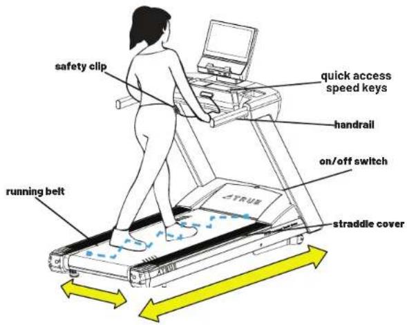
© 2024 TRUE Fitness All Rights Reserved.
Step 17-Adjust Running Belt Tensioning
| Tools Used in this Step | |
| 8mm T-Handle Allen Wrench |  |
| Long-Length Ruler 0"-48"/0 cm-120 cm | |
To tension the running belt:
A. Press Stop.
B. Turn the treadmill off.
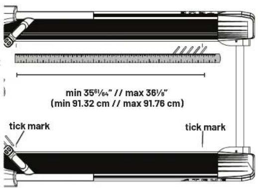
C. Rotate the running belt by hand so the four horizontal tick marks are visible.
D. Measure the distance between the tick marks on each side of the machine. The span should be at least 35^/_64'' (91.32 cm) but no greater than 3618'' (91.76 cm) on each side.
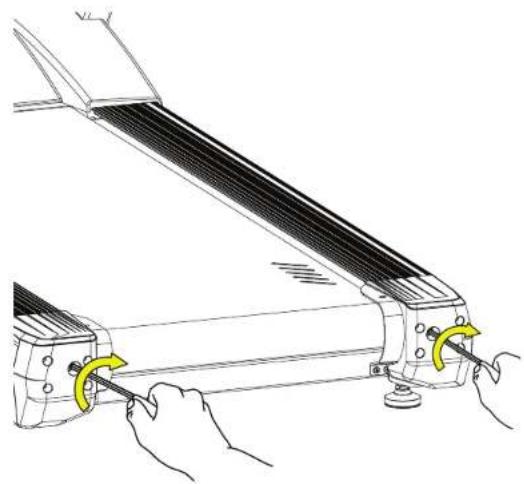
E. If the belt needs to be adjusted, locate the adjustment bolts at the rear of the treadmill.
F. On each side of the machine, turn the adjustment bolts clockwise 14 turn and remeasure.
G. When both sides are measuring within range, turn the treadmill on and start the belt at 3 mph (5 kph) keeping off the unit.
H. Allow 2 minutes for the belt to self adjust.
I. Check to see if the belt is still slipping.
Repeat these steps if additional tensioning is needed.
natural_image
Line drawing of a mechanical device with hands operating it, showing blade and adjustment arrows (no text or symbols)PRODUCT FEATURES
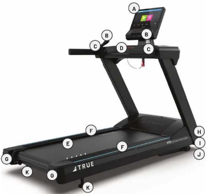
BASE OVERVIEW
A. Console Assembly The console allows the user to set up a workout program and control the treadmill during a workout.
B. Quick Access Keys Allows the user to quickly start, stop and wake the treadmill or make fast, convenient adjustments to the incline level or speed of the treadmill.
C. Contact Heart Rate Pads Allows the user to check their heart rate without wearing a wireless chest strap.
IMPORTANT! For increased safety and accuracy this feature should only be used when the belt speed is below 4 mph.
D. Safety (E-Stop) Key A tethered safety device designed to attach to both the user and the treadmill console. Removal of the key from the console will stop belt motion to prevent injury in an emergency.
IMPORTANT! The safety key must be in place on the treadmill, and should be attached to the user's clothing. The treadmill will not operate if the safety key is not attached to the treadmill.
E. Belt The moving surface of the treadmill on which the user walks or runs.
F. Straddle Covers Stationary covers on either side of the belt, which allows the user to safely straddle the belt during startup or in the event of an emergency.
G. Belt Adjustment Bolts An adjustment system that allows the users to adjust the belt tension as needed.
H. On/Off Switch Allows users or faculty to turn the power on or off to the treadmill.
I. Circuit Breaker A safety device designed to protect the treadmill from excessive electrical current.
J. Power Cord Delivers power from the wall outlet to the treadmill.
K. Leveling Feet An adjustable system used to aid in the leveling the treadmill.
CONSOLE OVERVIEW
It is important to perform the minor maintenance tasks described in this section. Failure to maintain the treadmill as described here could void the TRUE Fitness Warranty. To reduce the risk of electrical shock, always unplug the unit from its power source before cleaning or performing any maintenance tasks.
INSPECTION
TRUE is not responsible for performing or scheduling regular maintenance or inspections. Users should inspect the treadmill daily. Check for worn, frayed or missing safety lanyards. Replace missing or worn safety lanyards immediately. Do not exercise on the treadmill without attaching the safety clip to your clothing. Look and listen for loose fasteners, unusual noises, worn or frayed power cords, and any other indications that the equipment may be in need of service. If any of these are noticed, obtain service. Do not attempt to use the treadmill until proper service has been performed or damaged parts have been replaced.
IMPORTANT!
If you determine that the treadmill needs service, make sure that the treadmill cannot be used inadvertently. Turn the unit off, and then unplug the power cord from its power source. Remove the magnetic safety key and safety clip and store it in a safe place. Make sure other users know that the treadmill needs service. To order parts or to contact a TRUE authorized service representative, please visit www.truefitness.com.
CLEANING THE EQUIPMENT
AFTER EACH USE
• Use GymWipes™ Antibacterial wipes or spray a solution of 30 parts water to 1 part mild detergent to dampen a soft cloth and wipe all exposed surfaces.
- Use a LCD/screen cleaner or spray a solution of 1 part 91% isopropyl alcohol and 1 part water to dampen a soft cloth and wipe the surface of the console. This helps remove fingerprints, dust, and dirt.
WEEKLY
- Vacuum—Use a vacuum to remove any dust or dirt that might have accumulated under or around the treadmill, any motor cover vents, and under the straddle covers. Clogged air vents can prevent adequate cooling to the drive motor, incline motor, and motor control board causing a shortened life.
- Inspect Belt—Check for proper running belt alignment and tension. If running belt adjustment is required, please see the following pages for how to adjust.
CAUTION:
Do not use any acidic cleaners. Doing so will weaken the paint or powder coatings and may void the TRUE Fitness Warranty. Never pour water or spray liquids on any part of the treadmill. Allow the treadmill to dry completely before using. Frequently vacuum the floor underneath the unit to prevent the accumulation of dust and dirt, which can affect the smooth operation of the unit. Use a soft nylon scrub brush to clean the running belt. Do not clean directly underneath the treadbelt. Most of the working mechanisms are protected inside the motor cover and base of the treadmill. However, for efficient operation, the treadmill relies on low friction. To keep the friction low, the unit's running belt, staging platforms, and internal mechanisms must be as clean as possible.
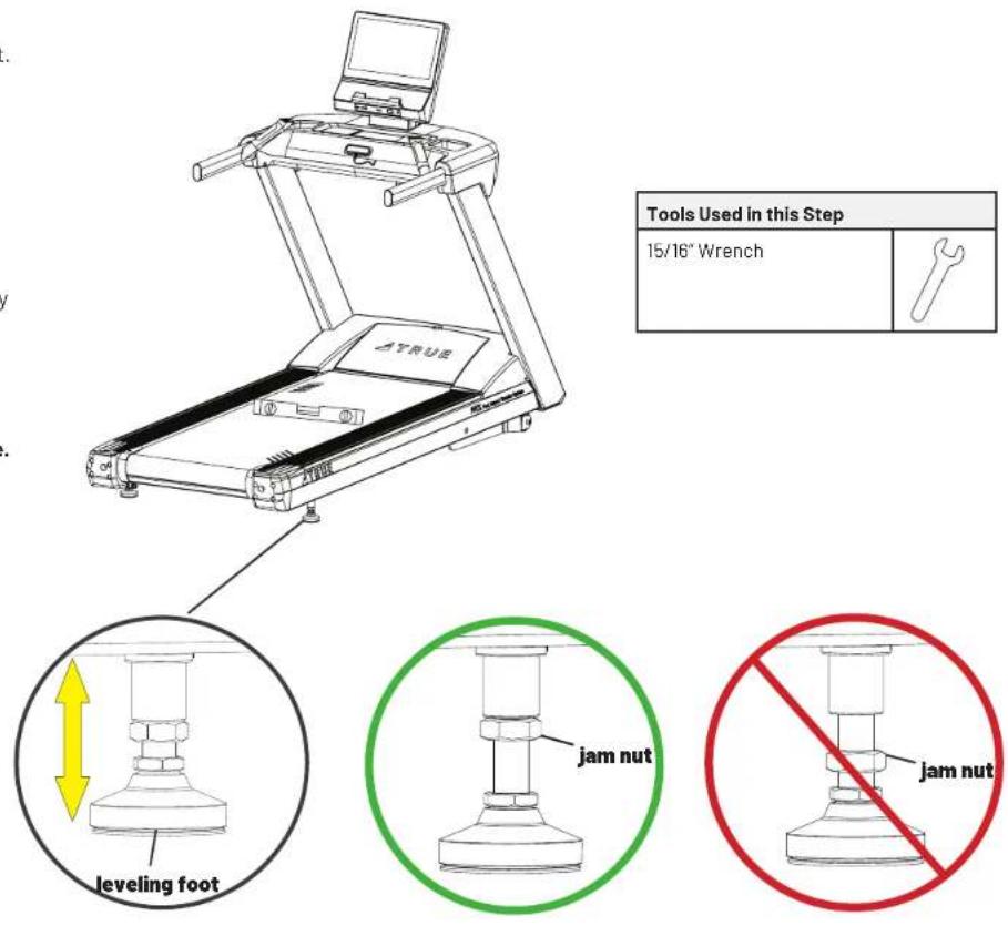
LEVELING THE MACHINE
CAUTION:
Prevent potential damage to the machine and injury to the user. This unit is equipped with adjustable rear leveling feet. Make sure that the running surface is level at all times. If the treadmill is placed on a uneven surface, adjusting the rear feet can help, but may not completely compensate for extremely uneven surfaces. Treadmills that are not level can cause misalignment of the belt, uneven belt wear, and possible injuries for the user.
Once the machine has been moved to it's designated location:
A. Verify the treadmill is resting on the floor and not on any packaging materials.
B. Using a 7/8" open end wrench, adjust the back right leveling foot until it contacts the floor.
IMPORTANT! Do not adjust the leveling foot to such a height that it detaches or unscrews from the machine.
C. Verify the lock nut is securely tightened and flush against the bottom of the frame.
RUNNING BELT ALIGNMENT
Proper belt alignment allows the belt to remain centered and ensures smooth operation. Realigning the belt takes a few simple adjustments. If you are unsure about this procedure, contact TRUE product support (service@truefitness.com | 800.883.8783).
IMPORTANT! Damage to the running belt due to improper belt adjustments is not covered under warranty.
CAUTION:
- Verify the treadmill is level before attempting any belt adjustments. An unstable unit may cause belt misalignment.
- Special care must be taken when aligning the running belt. Turn off the treadmill while adjusting or working near the rear roller. Remove any loose clothing and tie back your hair. Be very careful to keep your fingers and any other object clear of the belt and rollers, especially in front of the roller and behind the deck. The treadmill will not stop immediately if an object becomes caught in the belt or rollers.
- If you hear any chafing or the running belt appears to be getting damaged, stop the running belt immediately by pressing Stop. Walk around to the rear of the unit and observe the belt for a few minutes. The belt should be centered on the running deck. If the belt drifts off center, you must make adjustments.
• For your safety, use the power switch to turn off the treadmill before making any adjustments. Do not adjust the running belt when someone is standing on the unit. - Do not turn the adjusting bolt more than 14 turn at a time. Over tightening the bolt can damage the treadmill and over stretch the belt.
IMPORTANT! Failure to align the belt may cause the belt to tear or fray, which may not be covered under the TRUE Warranty.
To stop the running belt:
A. Press Stop.
B. Turn the treadmill off.
If the running belt is too far to the right side:
A. Locate the right side belt adjustment bolt at the rear of the treadmill.
(To determine left and right, stand at the rear of the treadmill and face the display.)
B. On the right side of the machine, turn the adjustment bolt clockwise 14 turn.
C. Turn the treadmill on and start the belt at 3 mph (5 kph) keeping off the unit.
D. Allow 2 minutes for the belt to self adjust.
Repeat these steps if additional adjustment is necessary.
If the running belt is too far to the left side:
A. Locate the left side belt adjustment bolt at the rear of the treadmill.
(To determine left and right, stand at the rear of the treadmill and face the display.)
B. On the left side of the machine, turn the adjustment bolt clockwise 14 turn.
C. Turn the treadmill on and start the belt at 3 mph (5 kph) keeping off the unit.
D. Allow 2 minutes for the belt to self adjust.
Repeat these steps if additional adjustment is necessary.
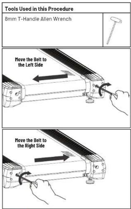
TENSIONING THE RUNNING BELT
If there is a slipping or jerking sensation when running on the treadmill, the running belt may require tightening. In most cases the belt has stretched from use. Tensioning the belt takes a few simple adjustments. If you are unsure about this procedure, contact product support (service@truefitness.com | 800.883.8783).
IMPORTANT! Damage to the running belt due to improper belt adjustments is not covered under warranty.
CAUTION:
- Verify the treadmill is level before attempting any belt adjustments. An unstable unit may cause belt misalignment.
- Special care must be taken when tensioning the running belt. Turn off the treadmill while adjusting or working near the rear roller. Remove any loose clothing and tie back your hair. Be very careful to keep your fingers and any other object clear of the belt and rollers, especially in front of the roller and behind the deck. The treadmill will not stop immediately if an object becomes caught in the belt or rollers.
• For your safety, use the power switch to turn off the treadmill before making any adjustments. Do not adjust the running belt when someone is standing on the unit. - Do not turn the adjusting bolt more than 14 turn at a time. Over tightening the bolt can damage the treadmill and over stretch the belt.
- If you tighten the belt and it still slips, the problem could actually be the drive belt, which is located under the motor cover and connects the motor to the front roller. If the drive belt is loose, it feels similar to the walking belt being loose. Tightening the drive belt should only be done by a trained service person, contact TRUE product support for assistance.
To tension the running belt:
A. Press Stop.
B. Turn the treadmill off.
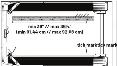
C. Rotate the running belt by hand so the four horizontal tick marks are visible.
D. Measure the distance between the tick marks on each side of the machine. The span should be at least 36"(91.44 cm) but no greater than 36 14 " (92.08 cm) on each side.
E. If the belt needs to be adjusted, locate the adjustment bolts at the rear of the treadmill.
F. On each side of the machine, turn the adjustment bolts clockwise 14 turn and remeasure.
G. When both sides are measuring within range, turn the treadmill on and start the belt at 3 mph (5 kph) keeping off the unit.
H. Allow 2 minutes for the belt to self adjust.
I. Check to see if the belt is still slipping.
Repeat these steps if additional tensioning is needed.
| Tools Used in this Procedure | |
| 8mm T-Handle Allen Wrench | 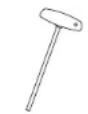 |
| Long-Length Ruler 0"-48"/0 cm-120 cm |  |

natural_image
Line drawing of hands operating a mechanical device with rotating buttons (no text or symbols)PREVENTATIVE MAINTENANCE
TRUE recommends that quarterly scheduled maintenance be performed by a qualified service technician. Please contact your dealer or visit www.truefitness.com to contact a local TRUE authorized service technician.
IMPORTANT! Use only TRUE Fitness certified service providers. Using non-authorized service providers could void the TRUE Warranty.
| Frequency Tasks | |
| Daily | Look and listen for loose fasteners, unusual noises, worn or frayed cables, and any other indications that the equipment may be in need of service.Use GymWipesTM Antibacterial wipes or spray a solution of 30 parts water to 1 part mild detergent to dampen a soft cloth and wipe all exposed surfaces.Use a LCD/screen cleaner or spray a solution of 1 part 91% isopropyl alcohol and 1 part water to dampen a soft cloth and wipe the surface of the console. This helps remove fi ingerprints, dust, and dirt. |
| Weekly | Vacuum any dust or dirt that might have accumulated under or around the treadmill. Clogged air vents can prevent adequate cooling to the drive motor, incline motor, and motor control board causing a shortened life.Check for proper slat belt tension. |
| Quarterly · Record time, distance, and hours from the console.Check error log in console.Remove shroud covers and vacuum any debris out of the speed sensor, control electronics and moving parts.Move and vacuum underneath the machine.Inspect all fasteners.Inspect all electrical connections.Inspect components for abnormal or premature wear. | |
LONG TERM STORAGE
When the treadmill is not in use for any length of time, turn it off. Make sure that the power cord is unplugged from the power source and is positioned so that it will not become damaged or interfere with people or other equipment.
CLEANING AND STORING THE CHEST STRAP
Clean the chest strap using a sponge or soft cloth dampened in mild soap and water. Dry the surface thoroughly with a clean towel. Store the chest strap in a place where it remains free of dust and dirt. Be sure to protect the chest strap from extreme temperatures. Do not store it in a place that may be exposed to temperatures below 32^(0^) .
ADDITIONAL INFORMATION
TROUBLESHOOTING
This troubleshooting information is intended to assist in diagnostics only and is not all inclusive. Technical specifications, error codes, and programming are subject to change without notice. TRUE accepts no liability for any damage or loss suffered by persons whom rely wholly or in part on any description or statement contained within this manual. Please visit www.truefitness.com to obtain the most recent version of all manuals and contact TRUE product support (800-883-8783) for assistance with troubleshooting and diagnostics.
| Malfunction Possible Cause Corrective | Action | |
| No Power | Unit turned off Verify the On/Off switch is at the ON position | |
| Damaged power cord Replace power cord | ||
| Power cord not fully seated in socket Inspect power connection at the unit and outlet | ||
| No power at outlet Using a voltmeter verify power at outlet | ||
| Tripped circuit breaker | The location of the circuit breaker is next to the On/Off switch. Verify the circuit breaker is not open. If the breaker is open reset. | |
| Unit resets or pauses randomly | Damaged power cord Replace power cord | |
| Power cord not fully seated in socket Inspect power connection at the unit and outlet | ||
| Safety e-stop key not fully engaged Re-engage the safety/e-stop key to the console | ||
| Nucleus board may be damaged Contact TRUE product support | ||
| Insufficient power | Verify output voltage from 20A outlet with a voltmeter | |
| Error code is displayed on console | Contact TRUE product support | |
| Pinched or loose main communication cable | ||
| No User Present displayed on screen | User weight must be over 90lbs. Verify No User Present settings in console. | |
| Walking belt hesitates or slips when stepping | Adjust belt tension | See Tensioning the Slat Belt |
| Rubbing sound from treadmill when in operation | Foreign object may be stuck under walking belt | Inspect under the unit. Remove and object that may be under the unit. |
| Foreign object may be stuck in motor compartment | Contact TRUE product support | |
| Rollers may be damaged or misaligned | ||
| Drive motor may be damaged | ||
| Drive belt may be misaligned | ||
| Slats may be loose or broken | ||
| Interference with anti-pinch bracket | ||
| Adjust belt tension | See Tensioning the Running Belt | |
| Heart rate is displaying erratically or not displaying | Transmitter belt contacts are not making good contact with the skin | Re-adjust the transmitter belt so that it is in full contact with the skin |
| Contacts on the transmitter belt are not moist Molster | the contacts on the transmitter belt | |
| Transmitter belt is not within 3 feet (1 meter) of the heart rate receiver | Adjust your position on the belt so that you are within 3 feet (1 meter) of the console | |
| The battery inside the transmitter belt is depleted Replace the transmitter belt with a compatible transmitter belt | ||
| Another user wearing a compatible transmitter strap is within 3 foot (1 meter) of the unit | Move the units so that there is more space in-between units | |
| Environmental interference from high voltage power lines | Move the unit to another position within the room or move the cause of the interference until heart rate reading are stable. If the probable source of interference is plugged into the same outlet move the suspect source to another outlet. | |
| Environmental interference from computers | ||
| Environmental interference from motor driven appliances | ||
| Environmental interference from cell or cordless phone | ||
| Environmental interference from Wi-Fi router | ||
| Contact Heart Rate not displaying | Machine needs to be restarted Power cycle | |
| Cables are pinched or damaged Contact TRUE product support | ||
| Nucleus board may be damaged Contact TRUE product support | ||
| Heart Rate Grips may be damaged Contact TRUE product support | ||
WIRING DIAGRAMS
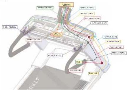
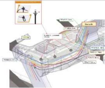
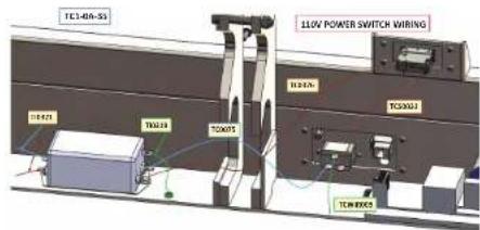
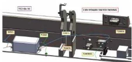
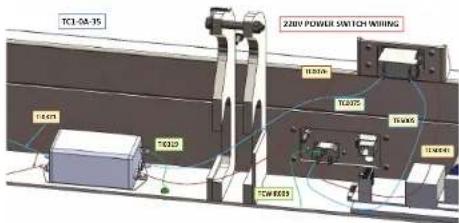
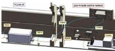
TC1-0A-35 and TC2-0A-35 Wiring Diagram
| Derived area | |
| Savills, 2013, 2014 | |
| Mallanese | |
| Cronbach's 2015 | |
| Capey | 8.7% |
| Duney | 26.4% |
| Ertley | 9.4% |
| Fremby | 26.4% |
| Grenzel | 26.4% |
| Hendel | 26.4% |
| Iberian | 26.4% |
| Larsen | 26.4% |
| Loyce | 26.4% |
| Pittig and 2015 | |
| Pittig and 2014 | |
| Other | |
| Added area | |
| 2.4-3.5 mm | |
| 1.5 mm | |
| 0.7-1.0 mm | |
| 1.0-1.5 mm | |
| 0.7-1.0 mm | |
| 1.0-1.5 mm | |
WARRANTY INFORMATION
COMMERCIAL WARRANTY
| CARDIO | ||||
| WARRANTY ITEM | VAPOR, APEX GRAVITY PLUS GRAVITY ADX, RO, SURGE | |||
| Frame* 7 Years 7 Years 7 Years 5 Years | ||||
| Parts 3 Years 3 Years 3 Years 3 Years | ||||
| Consoles 3 Years 3 Years 3 Years 2 Years | ||||
| Labor** 2 Years 2 Years 1 Year 1 Year | ||||
| Wear Items*** 180 Days 180 Days 180 Days 90 Days | ||||
| FLEXIBILITY | |
| WARRANTY ITEM | STRETCH |
| Parts | 1 Year |
| Wear Items*** | 90 Days |
| STRENGTH | |
| WARRANTY ITEM | PALLADIUM, FUSE XL, FORCE, FITNESS LINE, ATLAS, XFT, XFW, MP, SM, FT, FS |
| Frame* | 10 Years |
| Parts | 5 Years |
| Cables and Linear Bearings | 1 Year |
| Labor** | 1 Year |
| Wear Items*** | 90 Days |
Warranty does not cover damage or equipment failure resulting from or caused by improper assembly/installation, accident, misuse, abuse, unauthorized modification, or failure to provide reasonable and necessary maintenance.
*Frame is the serialized base of the unit and does not include paint or coatings.
**Labor is available for equipment located within United States and Canada.
***Wear Items include: batteries, covers, caps, badges, paint, pedal straps, toe clips, elliptical pedal inserts, foot pads, Coax/TV, HDMI, USB, mirroring or Ethernet connections, and safety key.
See Warranty Details for terms, conditions, and complete coverage details.
LIMITED-USE COMMERCIAL WARRANTY\*
| CARDIO | ||||
| WARRANTY ITEM | VAPOR, APEX | GRAVITY PLUS | GRAVITY LAUNCH | |
| Frame*** 7 Years | 7 Years 7 Years | 7 Years | ||
| Parts 5 Years 5 Years | 5 Years 3 Years | |||
| Consoles 3 Years | 3 Years 3 Years | 3 Years | ||
| Labor**** 3 Years | 3 Years 2 Years | 1 Year | ||
| Wear Items***** | 180 Days 180 Days | 180 Days 180 | Days | |
IN-HOME USE WARRANTY\*\*
| CARDIO | ||||
| WARRANTY ITEM | VAPOR, APEX | GRAVITY PLUS | GRAVITY LAUNCH | |
| Frame*** 12 Years | 12 Years 12 Years | 7 Years | ||
| Parts 10 Years 7 Years | Years 7 Years 5 Years | |||
| Consoles 3 Years | 3 Years 3 Years | 3 Years | ||
| Labor**** 2 Years | 1 Year | 1 Year | 1 Year | |
| Wear Items***** 180 Days | Days 180 Days | Days 180 Days | Days | |
TRUE Fitness may offer alternative warranties to purchasers of commercial equipment for limited-use commercial* or in-home use.** This policy ensures that customers who use commercial equipment for limited-use commercial or in-home use may receive alternative warranty coverage, provided they meet the specified requirements. It's important to note that the specific terms and conditions of the alternative warranty, as well as the eligibility criteria, may vary depending on the product and TRUE's policies at the time of purchase. Customers should review the warranty terms and contact TRUE for precise details.
*To be eligible for the alternative limited-use commercial warranty, equipment use cannot exceed 6-hours use a day or be for use in a membership, dues paying, or institutional facility.
**To be eligible for the alternative in-home use warranty, equipment must be registered to a home address and cannot be used outside of the purchaser of the equipment and their immediate family.
Customers must provide TRUE with the following within 30 days of installation of the commercial-rated equipment:
• Purchase agreement.
• Proof of professional delivery and installation.
- TRUE will register the alternative warranty for the purchaser and implement it within 90 days of receiving the required documentation if such an alternative warranty is available for the specific product.
Warranty does not cover damage or equipment failure resulting from or caused by improper assembly/installation, accident, misuse, abuse, unauthorized modification, or failure to provide reasonable and necessary maintenance.
***Frame is the serialized base of the unit and does not include paint or coatings.
****Labor is available for equipment located within United States and Canada.
*****Wear Items include: batteries, covers, caps, badges, paint, pedal straps, toe clips, elliptical pedal inserts, foot pads, Coax/TV, HDMI, USB, mirroring or Ethernet connections, and safety key.
See Warranty Details for terms, conditions, and complete coverage details.
WARRANTY DETAILS
All TRUE Fitness products are distributed by TRUE and are warranted to the original registered product purchaser and the parts of the TRUE product (the "Product") listed below, under normal use and service, shall be free of manufacturing defects in workmanship and materials only for the specified period of time.
NOTE:
- Standard shipping is included with warranty part replacement.
• Shipping for warranty frame or replacement is included for the period of three years from the original date of purchase.
All Warranty Items are "LIMITED"
- This limited warranty does not cover damage or equipment failure resulting from or caused by improper assembly/installation, failure to follow instructions and warnings in owner's manual, accident, misuse, abuse, unauthorized modification, failure to provide reasonable and necessary maintenance, software version upgrades, compatibility with third party/aftermarket hardware, software, applications, or websites.
- TRUE's liability shall under no circumstances exceed the actual amount paid by you for the product, nor shall TRUE under any circumstances be liable for any consequential, incidental, special or punitive damages or losses, whether direct or indirect.
• Some states or countries do not allow the exclusion or limitation of incidental or consequential damages, so the above limitation or exclusion may not apply to you. - TRUE will neither assume nor authorize any person to assure for us any other obligation or liability concerning the sale of this Product. Under no circumstances shall TRUE be liable under this warranty, or otherwise, of any damage to any person or property, including any lost profits or lost savings, for any special, indirect, secondary, incidental, or consequential damages arising out of the use of or inability to use this Product.
- This limited warranty, which is given expressly and in lieu of all other express warranties, constitutes the only warranty made by TRUE.
• The remedies described herein are your sole and exclusive remedies and TRUE's entire liability for any breach of this limited warranty. - No one is authorized to change, modify, or extend the terms of this limited warranty.
• This limited warranty is in lieu of all other warranties of any kind either expressed or including but not limited to implied warranties of merchant.
• This limited warranty applies to the product only while the product remains in the possession of the original purchaser and is not transferable. - This limited warranty becomes VALID ONLY if the Product is initially assembled/installed by a TRUE authorized dealer/technician (if anyone other than a TRUE authorized dealer/technician initially assembles and installs the Product, this limited warranty will be void unless the written authorization of TRUE is first obtained).
- This limited warranty can be processed only if the warranty registration form is completed on-line; or if the form provided with equipment is filled in, signed by the original purchaser, and mailed to TRUE within 30 days of purchaser's receipt of this Product.
- All serial numbers must be intact on the Product for this limited warranty to be valid.
- Installation or download of any 3rd party or after-market products will result in voided warranty. This includes, but is not limited to, electrical and mechanical parts, software, or applications.
• TRUE will ship to an authorized service provider any new or rebuilt replacement part or component, or at our option, replace or refund the Product. - Replacement parts are warranted for the remaining portion of the original warranty period.
• Proof/receipts of necessary maintenance may be required within 30 days of requested warranty part or service. - This limited warranty does not apply to the performance of the heart rate accuracy will not be warranted as performance varies, based on user's physiology, age, method of use, and other eternal factors.
WARRANTY REGISTRATION
Thank you for purchasing a TRUE product!
For warranty terms and conditions, see the complete owner's manual and assembly guide located at truefi tness.com.
To validate your product warranty, you must register your product within 30 days of purchaser's receipt of this product.
To register your product:
- Go online to: https://truefitness.com/services-support/warranty-registration/ OR
- Complete the information below and mail to:
TRUE Product Support
865 Hoff Road
St. Louis, MO 63366
PLEASE RETAIN THIS PORTION FOR YOUR RECORDS
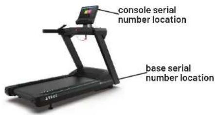
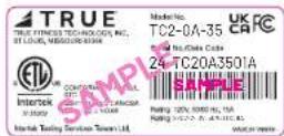
BASE SERIAL NUMBER:
CONSOLE SERIAL NUMBER:
natural_image
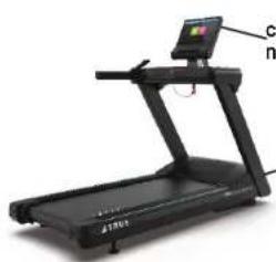
Black treadmill with a digital display and control panel, no visible text or symbols on the device itself.console serial number location
base serial number location

WARRANTY REGISTRATION
Base Serial Number
Purchase Date
Customer Name (First and Last)
Email Address
Street Address City
Postal Code Country
Console Serial Number
Company (if applicable)
Phone Number

State
TRUE FITNESS
CONTACT US
service@truefi tness.com
800.883.8783
865 Hoff Road
St. Louis, MO 63366
TRUEFITNESS.COM

MAN-TC2-0A-35 Owner's Manual and Assembly Guide REV02
© 2024 TRUE Fitness All Rights Reserved.
- GRAVITY PLUS TREADMILL
- IMPORTANT-PLEASE READ
- CONTACTING OUR SUPPORT TEAM
- CONTACTING OUR SALES TEAM
- REPORTING FREIGHT CLAIMS OR PARTS DAMAGE
- Severe Damage—Obvious damage to external packaging and internal product.
- Slight Damage—Minimal damage to external packaging with unknown internal damage to product.
- Concealed Damage—No damage to external packaging but internal damage to product.
- TABLE OF CONTENTS
- SAFETY INSTRUCTIONS
- ASSEMBLY INSTRUCTIONS
- PRODUCT FEATURES
- CARE AND MAINTENANCE
- ADDITIONAL INFORMATION
- WARRANTY INFORMATION
- IMPORTANT SAFETY INSTRUCTIONS—SAVE THESE INSTRUCTIONS
- POWER REQUIREMENTS
- DEDICATED LINE
- GROUNDING INSTRUCTIONS
- ! DANGER:
- SPACE REQUIREMENTS
- SPECIFICATIONS
- WARNING DECALS
- COMPLIANCES
- PROPER TRAINING POSITION AND TREADMILL SAFETY
- Treadmill Entry
- Treadmill Use
- Treadmill Exit
- PREASSEMBLY CHECKLIST
- BASIC GUIDELINES FOR SETTING UP THE EQUIPMENT
- CAUTION:
- VERIFY BOX CONTENTS
- HARDWARE PACK CONTENTS
- ASSEMBLY STEPS
- Step 1—Remove Motor Cover Plastics
- Step 4-Attach Console Rack Continued
- IMPORTANT! DO NOT pinch the cables.
- Step 5—Connect Console Rack Cables
- Optional Step 6—Attach Decline Foot Assembly
- Optional Step 6—Attach Decline Foot Assembly Continued
- Optional Step 8—Install 220V Power Inlet Assembly
- Step 9—Attach Power Cord
- IMPORTANT STEP—DO NOT SKIP!
- Step 10—Configure the Console with the Base and Run Calibration\*
- Step 11—Reattach Motor Cover Plastics Continued
- Step 12—Reattach Lower Console Rack Covers
- Step 16-Break in Belt and Deck
- Step 17-Adjust Running Belt Tensioning
- To tension the running belt:
- BASE OVERVIEW
- CONSOLE OVERVIEW
- INSPECTION
- IMPORTANT!
- CLEANING THE EQUIPMENT
- AFTER EACH USE
- WEEKLY
- LEVELING THE MACHINE
- RUNNING BELT ALIGNMENT
- IMPORTANT! Failure to align the belt may cause the belt to tear or fray, which may not be covered under the TRUE Warranty.
- If the running belt is too far to the right side:
- If the running belt is too far to the left side:
- TENSIONING THE RUNNING BELT
- PREVENTATIVE MAINTENANCE
- LONG TERM STORAGE
- CLEANING AND STORING THE CHEST STRAP
- TROUBLESHOOTING
- WIRING DIAGRAMS
- COMMERCIAL WARRANTY
- LIMITED-USE COMMERCIAL WARRANTY\*
- IN-HOME USE WARRANTY\*\*
- WARRANTY DETAILS
- NOTE:
- All Warranty Items are "LIMITED"
- WARRANTY REGISTRATION
- TRUE FITNESS
Brand : True
Model : Gravity Plus
Category : Treadmills