
356BK - Attic Fan BROAN - Free user manual and instructions
Find the device manual for free 356BK BROAN in PDF.


| Product Type | Roof-Mount Powered Attic Ventilator |
| Model Number | 356BK |
| Finish | Black plastic dome |
| Intended Use | General residential attic ventilation |
| Mounting Location | Roof, centered on rear slope, as high as possible |
| Cutout Diameter (Roof Board) | 14-3/8 inches |
| Cutout Diameter (Shingles) | 17-1/2 inches |
| Thermostat Range | 70°F to 130°F (adjustable) |
| Thermostat Differential | 10°F (fan off when temperature drops 10°F below setpoint) |
| Automatic Operation | Yes, via built-in adjustable thermostat |
| Manual Override | Possible with optional bypass switch |
| Power Supply | 120 V AC, 60 Hz |
| Wiring Requirement | Permanent wiring, 14 AWG minimum copper wire, grounded |
| Extension Cord | Not allowed |
| Solid State Speed Control | Not to be used (Model 356 only) |
| Inlet Ventilation Requirement | HVI recommends 1 sq ft open air inlet per 300 CFM |
| Motor Type | Permanently lubricated, automatic reset thermal protection |
| Dome Material | Plastic (PVC) |
| Flashing Material | Galvanized steel |
| Paintable | Yes, dome can be painted with high-quality paint |
| Corrosion Resistance | Galvanized steel can remain rust-free up to 100 years under ideal conditions; painting recommended in polluted areas |
| Maintenance | Periodic cleaning; avoid drywall spray and construction dust |
| Safety Shock Protection | Must be grounded; disconnect power before servicing |
| Warranty | One year limited warranty |
| Spare Parts Available | Yes, including dome, fan blade, motor, roof plate, thermostat, wiring box, etc. |
| Manual Reference | User manual included; also available online |
Frequently Asked Questions - 356BK BROAN
User questions about 356BK BROAN
0 question about this device. Answer the ones you know or ask your own.
Ask a new question about this device
Download the instructions for your Attic Fan in PDF format for free! Find your manual 356BK - BROAN and take your electronic device back in hand. On this page are published all the documents necessary for the use of your device. 356BK by BROAN.
USER MANUAL 356BK BROAN
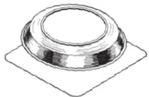
ROOF-MOUNT POWERED ATTIC VENTILATOR
natural_image
Simple line drawing of a dome-shaped object on a square base (no text or symbols)READ AND SAVE THESE INSTRUCTIONS
WARNING
TO REDUCE THE RISK OF FIRE, ELECTRIC SHOCK, OR INJURY TO PERSONS, OBSERVE THE FOLLOWING:
- Use this unit only in the manner intended by the manufacturer. If you have questions, contact the manufacturer at the address or telephone number listed in the warranty.
- Before servicing or cleaning unit, switch power off at service panel and lock the service disconnecting means to prevent power from being switched on accidentally. When the service disconnecting means cannot be locked, securely fasten a prominent warning device, such as a tag, to the service panel.
- Installation work and electrical wiring must be done by a qualified person(s) in accordance with all applicable codes and standards, including fire-rated construction codes and standards.
- Sufficient air is needed for proper combustion and exhausting of gases through the flue (chimney) of fuel burning equipment to prevent backdrafting. Follow the heating equipment manufacturer's guidelines and safety standards such as those published by the National Fire Protection Association (NFPA), and the American Society for Heating, Refrigeration and Air Conditioning Engineers (ASHRAE), and the local code authorities.
- When cutting or drilling into wall or ceiling, do not damage electrical wiring and other hidden utilities.
- The wiring must be permanent. DO NOT USE AN EXTENSION CORD! Use 14 GA. MINIMUM copper wire. Although the Powered Attic Ventilator may be wired directly to power, we advise that some type of shut off switch be installed in the line. Please see the section on electrical wiring for suggested wiring diagrams and instructions.
- This unit must be grounded.
- Do not use this unit with any solid state speed control device (Models 356 only).
TOOLS AND MATERIALS REQUIRED
☐ Slotted Screwdriver
Drill
1/4" Drill Bit
□ Sabre Saw or eyhole Saw
□ Hammer
Ruler
Pencil
Utility Knife
☐ Pry Bar (to remover roofing nails)
Roofing Cement
☐ Galvanized Roofing Nails (1 ^3/4 " min.)
☐ Electrical Supplies (to comply with codes)
CAUTION

- For general ventilating use only. Do not use to exhaust hazardous or explosive materials and vapors.
- To avoid motor bearing damage and noisy and/or unbalanced impellers, keep drywall spray, construction dust, etc. off power unit.
- This unit has an unguarded impeller. Do not use in locations readily accessible to people or animals.
- Fan is equipped with a thermostat which may start fan automatically. To reduce risk of injury or electric shock while servicing or cleaning unit, switch power off at service panel and lock service panel to prevent power from being switched on accidentally. When the service disconnecting means cannot be locked, securely fasten a prominent warning device, such as a tag, to the service panel.
- Home Ventilating Institute (HVI) recommends one square foot of open air inlet per 300 cfm of fan capacity. The best location for these air intake vents are under the eaves with direct access to the attic. Failure to provide these intakes could cause natural-draft gas appliances to backdraft.
- Your attic fan installation will create a screened opening into your attic space. During a heavy rain storm there could be a light spray of rain into this attic space. This is a normal condition with all attic ventilators and will not cause any damage to the structure. We recommend that you do not store any valuable articles directly under the fan opening in the roof. During extreme rain and wind storms you may want to turn on your attic ventilator to prevent excess moisture accumulation in your attic.
- Records show, under ideal conditions, exposed galvanized steel can remain rust free up to 100 years. For best protection, the exposed portion of the roof sheet should be painted, especially in areas of unusually high industrial air pollution. Follow paint manufacturer's instructions for good adhesion.
- This ventilator is intended for roof installation. The Broan Model 353 Gable Mount Ventilator is available for side wall applications.
- The dome may be painted with a high-quality paint. Follow the paint manufacturer's recommendations for PVC plastic or aluminum, as appropriate.
- Please read specification label on product for further information and requirements.
- The wearing of safety glasses and gloves is recommended when installing, maintaining or cleaning the unit to reduce the risk of injury that could be caused by the presence of thin metal and/or high moving parts.
- If the fan makes excessive noise or if there is unusual noise or smells of smoke, disconnect power supply and contact customer service.
A. Use only in single family, residential garages
B. Install in a GFCI protected branch circuit
C. To help offset the risk posed by high concentrations of vapors from paints, glues, solvents, and fuels, install fan at least 18 inches (0.5m) above the floor
D. NEVER run a vehicle or use a fuel burning appliance inside of a garage. Deadly levels of carbon monoxide can build up in the area. Using this garage fan, or opening windows and doors, will NOT supply enough fresh air to eliminate the danger.
E. Run regularly if exposed to salty air environments
F. Extra cleaning may be required due to possible dirty surroundings
If this fan is to be used to ventilate a garage:
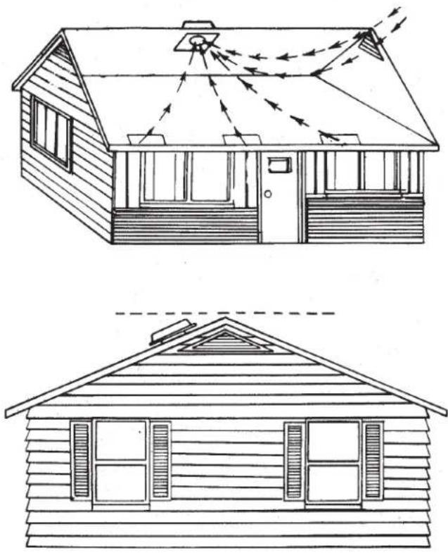
1. Locate the ventilator at the center of the rear slope of the roof. Place it as high on the roof as possible. The location should be free of obstacles (T.V. leads, electrical lines, etc.) If the ventilator top is level with the roof peak, it can't be seen from the street. Keep this approximate location in mind as you work from within the attic.
natural_image
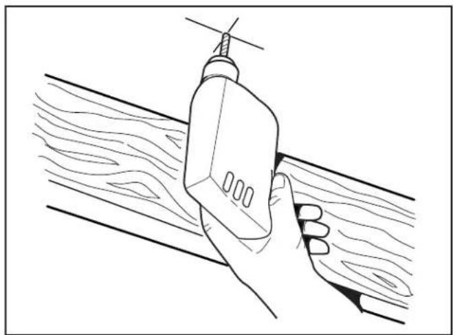
Line drawing of a hand holding a tool against a wooden surface (no text or symbols)- Drill a guide hole through the roof at this mark.
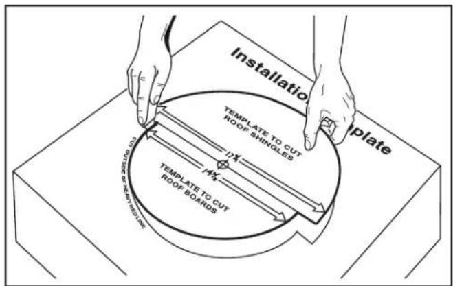
- Cut out the template found on the carton.
natural_image
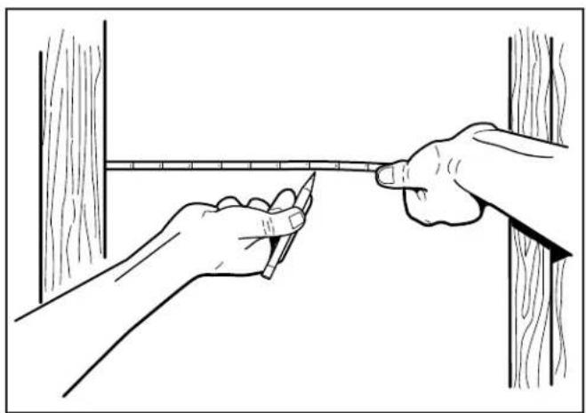
Illustration of hands measuring a vertical measurement with a ruler, against a wooden wall (no text or symbols)- Mark a spot halfway between rafters.
natural_image
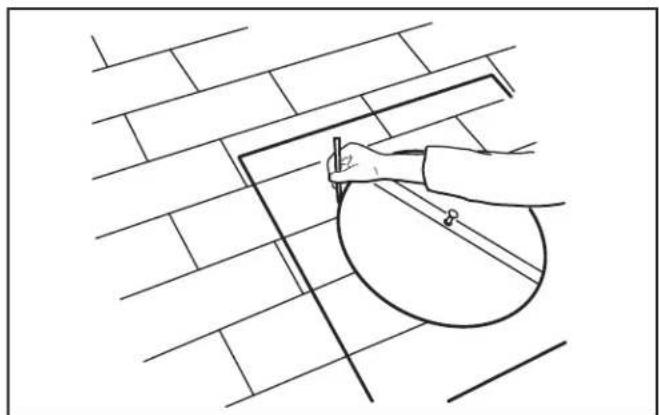
Line drawing of a hand using a tool to cut a circular object on a brick wall (no text or symbols)- Push a large nail through the center of the cardboard template and into the guide hole.
Using the large half of the template, draw a 17½" diameter circle on the shingles.
natural_image
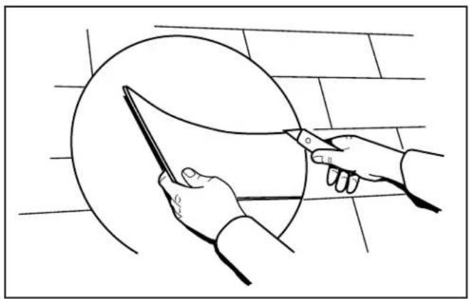
Line drawing of hands using a tool to cut a circular object, no text or symbols present- Cut out the shingles inside of the circle.
natural_image
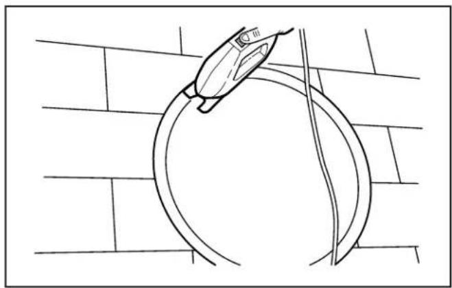
Line drawing of a hand holding a tool near a circular object on a brick wall (no text or symbols)- Cut out the roof board(s) inside of the line.
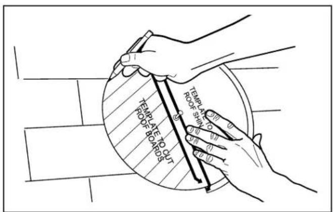
- Replace template over guide hole and draw a 14-3/8" diameter circle on the black paper or roof boards using the smaller half of the template.
natural_image
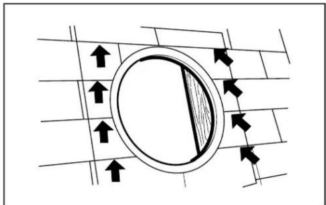
Diagram showing directional arrows around a circular object on a grid background (no text or symbols)- For proper removal of roofing nails, draw a 22" square, centered around the hole. Remove nails holding shingles down from top two-thirds of square.
natural_image
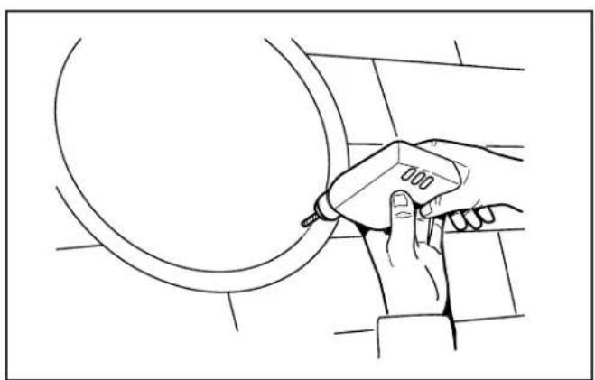
Line drawing of a hand using a tool to clean or repair a circular pipe (no text or symbols)- Drill a large starting hole for the sabre saw just inside of the line.
natural_image
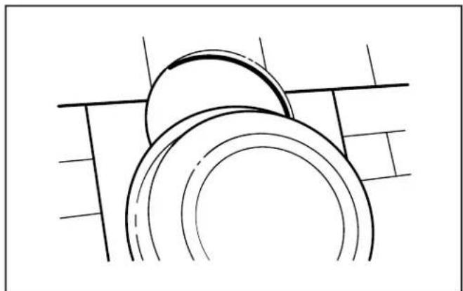
Pure technical line drawing of a mechanical component with no text or symbols- Slide the flashing under the shingles. Start two-thirds of the way down from the top of the 22" square. Do not bend the shingles any more than necessary. Center the ventilator over the hole.
natural_image
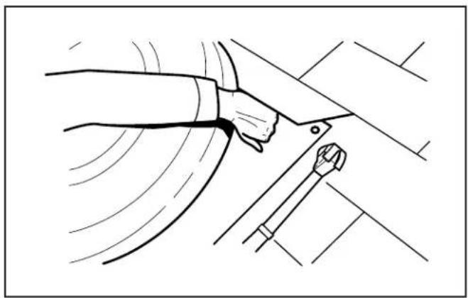
Line drawing of a hand using a tool to adjust or install a car wheel (no text or symbols present)- Carefully lift shingles and nail flashing securely to the roof using galvanized roofing nails.
natural_image
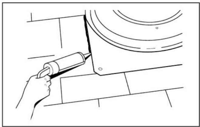
Line drawing of a hand using a tool to adjust or install a component on a surface (no text or symbols)-
Using a good grade of roofing cement material, seal all of the shingles and heads of nails.
DO NOT seal the bottom edge of the flashing. -
Remove the thermostat wiring box cover plate. Bring the power cable at least 6" into the ventilator wiring box. Fasten power cable to box with appropriate connector.
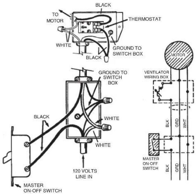
- For standard installation, connect the two leads in the thermostat wiring box to the two power leads. Attach ground wire from the power cable to the green screw in the box.
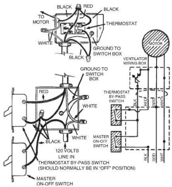
This diagram shows how to by-pass the thermostat to turn the ventilator on or off manually.
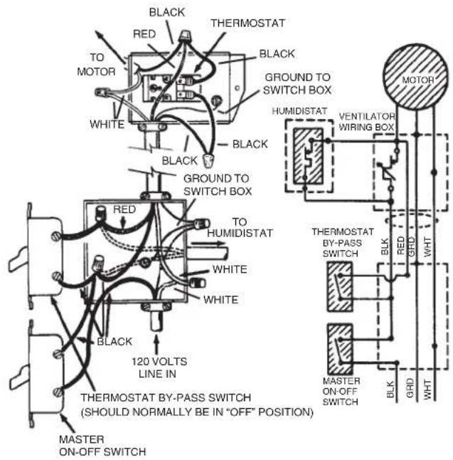
This diagram shows how to wire a humidistat.
- Replace the metal cover plate over the thermostat wiring box and fasten securely.
- The thermostat setting determines the temperature at which the ventilator turns "on". The ventilator automatically turns off when the attic temperature is 10^ F lower than the thermostat.
If you want the ventilator to operate at a different temperature, insert a screwdriver into the slot and turn the indicator to the desired temperature.
The ventilator will now turn "ON" at this temperature and "OFF" 10°F lower.
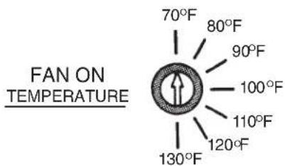
Indicator shown rotated fully counterclockwise for a setting of 70°F.
SERVICE PARTS
| KEY PART NO. | NUMBER | DESCRIPTION |
| 1 99150493 | #8B-18 x 1/2 Sheet Metal Screw* (3 Required) | |
| 2 99110689 | Plastic Dome (Models 350, 355, 356) | |
| 99111463 | Plastic Dome, Black (Models 350BK, 355BK, 356BK) | |
| 99111462 | Plastic Dome, Brown (Models 350BR, 355BR, 356BR) | |
| 3 | 97006971 Fan Blade with Setscrew | |
| 4 | 97009316 Motor (Models 350, 350BK, 350BR) | |
| 97009317 Motor (Models 355, 355BK, 355BR) | ||
| 97015612 Motor (Models 356, 356BK, 356BR) | ||
| 5 | 97008505 Roof Plate Assembly | |
| 6 | 98008298 Motor Mount Band (3 Required) | |
| 7 | 99170254 Screw, 5/16-18 x 3/4 Hex Head Machine Screw* (3 Required) | |
| 8 | 99260465 Nut, 5/16-18 Hex* (3 Required) | |
| 9 | 99150524 Screw, 1/4 -20 x 1/2* (3 Required) | |
| 10 | 99170245 #8B-18 x 3/8 Sheet Metal Screw* (3 Required) | |
| 11 | 98009756 Wiring Box (Models 350, 350BK, 350BR, 355, 355BK, 355BR) | |
| 98009886 Wiring Box (Models 356, 356BK, 356BR) | ||
| 12 | 99150471 Green Ground Screw, #10-32 x 1/2 Hex Washer Head* | |
| 13 | 99030144 Adjustable Thermostat | |
| 14 | 97005329 Lead Wire Assembly | |
| 15 & 16 | 990717160 Wiring Box Cover with Label (Model 350) | |
| 990717161 | Wiring Box Cover with Label (Model 355) | |
| 990717250 | Wiring Box Cover with Label (Model 356) | |
| 990722489 | Wiring Box Cover with Label (Model 350BR) | |
| 990722490 | Wiring Box Cover with Label (Model 350BK) | |
| 990722491 | Wiring Box Cover with Label (Model 355BR) | |
| 990722492 | Wiring Box Cover with Label (Model 355BK) | |
| 990722493 | Wiring Box Cover with Label (Model 356BR) | |
| 990722494 | Wiring Box Cover with Label (Model 356BK) | |
| **17 | 99250948 Washer* (3 Required) |
*Standard Hardware. May be purchased locally.
**May be removed when serviced.
SERVICE PARTS
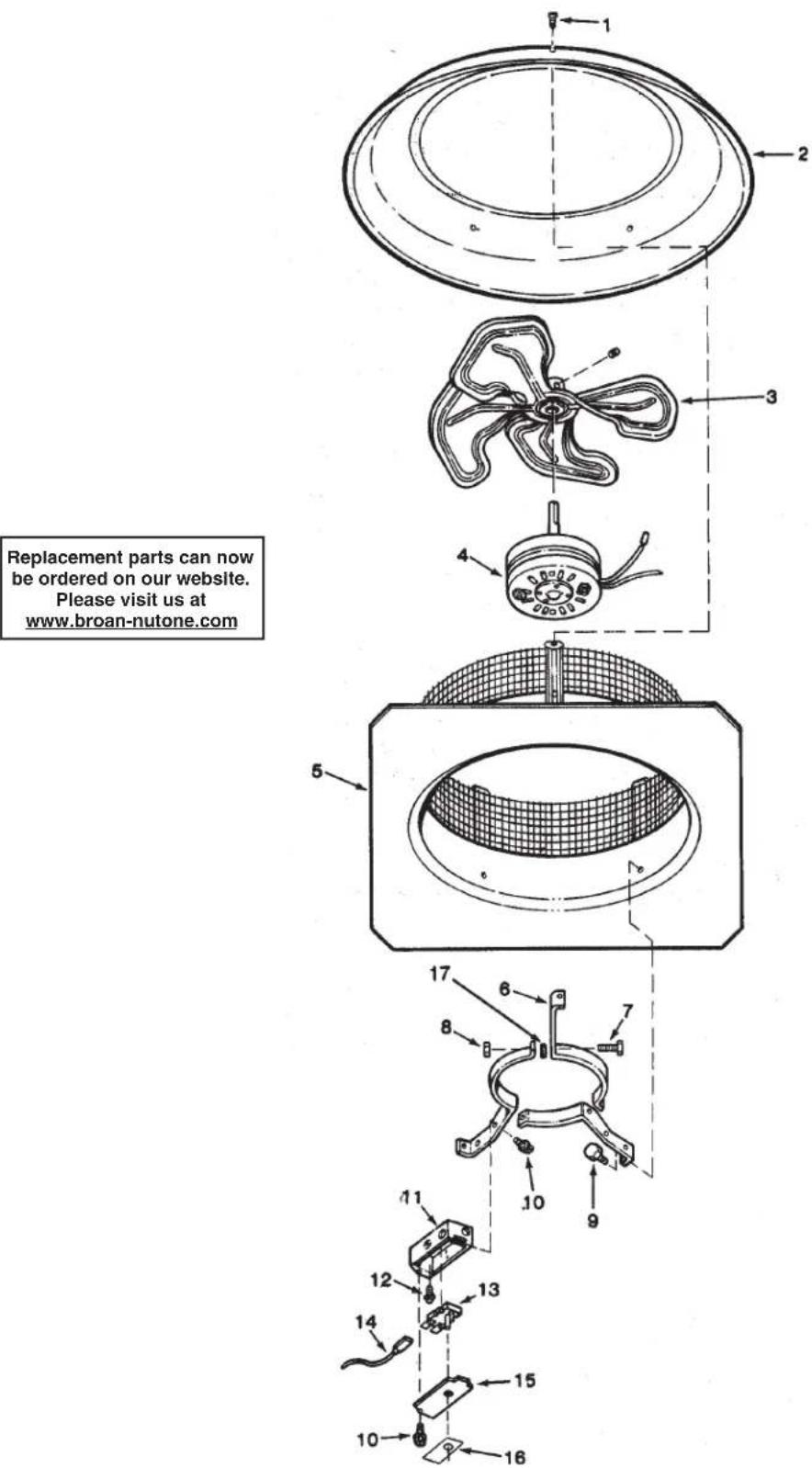
WARRANTY
BROAN-NUTONE ONE YEAR LIMITED WARRANTY
Broan-NuTone warrants to the original consumer purchaser of its products that such products will be free from defects in materials or workmanship for a period of one year from the date of original purchase. THERE ARE NO OTHER WARRANTIES, EXPRESS OR IMPLIED, INCLUDING, BUT NOT LIMITED TO, IMPLIED WARRANTIES OF MERCHANTABILITY OR FITNESS FOR A PARTICULAR PURPOSE.
During this one-year period, Broan-NuTone will, at its option, repair or replace, without charge, any product or part which is found to be defective under normal use and service.
THIS WARRANTY DOES NOT EXTEND TO FLUORESCENT LAMP STARTERS AND TUBES. This warranty does not cover (a) normal maintenance and service or (b) any products or parts which have been subject to misuse, negligence, accident, improper maintenance or repair (other than by Broan-NuTone), faulty installation or installation contrary to recommended installation instructions.
The duration of any implied warranty is limited to the one-year period as specified for the express warranty. Some states do not allow limitation on how long an implied warranty lasts, so the above limitation may not apply to you.
BROAN-NUTONE'S OBLIGATION TO REPAIR OR REPLACE, AT BROAN-NUTONE'S OPTION, SHALL BE THE PURCHASER'S SOLE AND EXCLUSIVE REMEDY UNDER THIS WARRANTY. BROAN-NUTONE SHALL NOT BE LIABLE FOR INCIDENTAL, CONSEQUENTIAL OR SPECIAL DAMAGES ARISING OUT OF OR IN CONNECTION WITH PRODUCT USE OR PERFORMANCE. Some states do not allow the exclusion or limitation of incidental or consequential damages, so the above limitation or exclusion may not apply to you.
This warranty gives you specific legal rights, and you may also have other rights, which vary from state to state. This warranty supersedes all prior warranties.
To qualify for warranty service, you must (a) notify Broan-NuTone at the address or telephone number below, (b) give the model number and part identification and (c) describe the nature of any defect in the product or part. At the time of requesting warranty service, you must present evidence of the original purchase date.
Broan-NuTone LLC Hartford, Wisconsin www.broan-nutone.com 800-558-1711
- ROOF-MOUNT POWERED ATTIC VENTILATOR
- READ AND SAVE THESE INSTRUCTIONS
- WARNING
- TO REDUCE THE RISK OF FIRE, ELECTRIC SHOCK, OR INJURY TO PERSONS, OBSERVE THE FOLLOWING:
- TOOLS AND MATERIALS REQUIRED
- CAUTION
- If this fan is to be used to ventilate a garage:
- SERVICE PARTS
- WARRANTY
- BROAN-NUTONE ONE YEAR LIMITED WARRANTY
Brand : BROAN
Model : 356BK
Category : Attic Fan