C4-1-NDI-W - Security Camera DVDO - Free user manual and instructions
Find the device manual for free C4-1-NDI-W DVDO in PDF.


| Product Type | Full HD PTZ Security Camera |
| Model | C4-1-NDI-W |
| Image Sensor | 1/2.8-inch CMOS, 2.07 MP |
| Resolution | Up to 1920x1080 @ 60fps |
| Optical Zoom | 20x (5.2-98mm) |
| Horizontal Field of View | 56° (Wide) - 3.2° (Tele) |
| Minimum Illumination | 0.5 Lux (F1.8, AGC ON) |
| Video Outputs | HDMI, SDI, CVBS, LAN (PoE), USB 3.0 |
| Pan Range | -170° to +170° |
| Tilt Range | -30° to +90° |
| Pan Speed | 0.1°/s to 100°/s |
| Tilt Speed | 0.1°/s to 45°/s |
| Presets | Up to 255 (10 via remote) |
| AI Features | Real-Time and Regional Human Tracking |
| Video Compression | H.264/H.265, MJPEG, YUY2, NV12 |
| Audio Compression | AAC, MP3, G.711A |
| Network Protocols | ONVIF, GB/T28181, RTSP, RTMP, SRT, VISCA over IP |
| Control Interfaces | RS232 (IN/OUT), RS422/RS485, IR/Wireless Remote |
| Power Supply | DC 12V ±10%, <1A, PoE (LAN) |
| Power Consumption | <12W |
| Dimensions (W×H×D) | 181 mm × 115 mm × 149 mm |
| Weight | 1.15 kg |
| Working Temperature | -10°C to +50°C |
| Storage Temperature | -10°C to +70°C |
| Housing Material | Organic materials (indoor use) |
| Accessories Included | Power adapter, RS232 cable, USB 3.0 cable, remote control, manual |
| Cleaning | Soft dry cloth; mild detergent if needed; avoid strong/corrosive detergents |
| Safety Warnings | Do not open case; avoid rain/moisture; use qualified technician for installation |
Frequently Asked Questions - C4-1-NDI-W DVDO
User questions about C4-1-NDI-W DVDO
0 question about this device. Answer the ones you know or ask your own.
Ask a new question about this device
Download the instructions for your Security Camera in PDF format for free! Find your manual C4-1-NDI-W - DVDO and take your electronic device back in hand. On this page are published all the documents necessary for the use of your device. C4-1-NDI-W by DVDO.
USER MANUAL C4-1-NDI-W DVDO
natural_image
Close-up of a black video camera with lens and support bracket (no text or symbols visible)DVDO-C4-1
Full HD PTZ Camera
User Manual
Version: V1.0.0
Precaution
Improper operations may damage the product and result in mechanical failure.
Please note the following:
natural_image
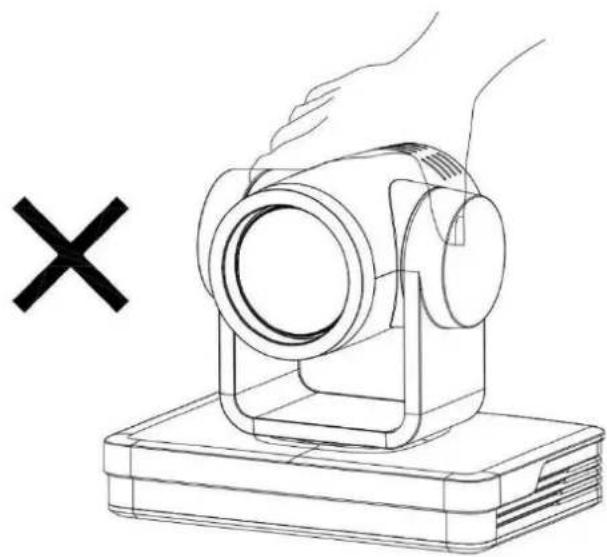
Line drawing of a hand holding a camera on a base, with a black 'X' symbol nearby (no text or symbols on the diagram itself)Do not move the camera by grabbing the head.
Move the camera by holding the bottom with one or both hands.

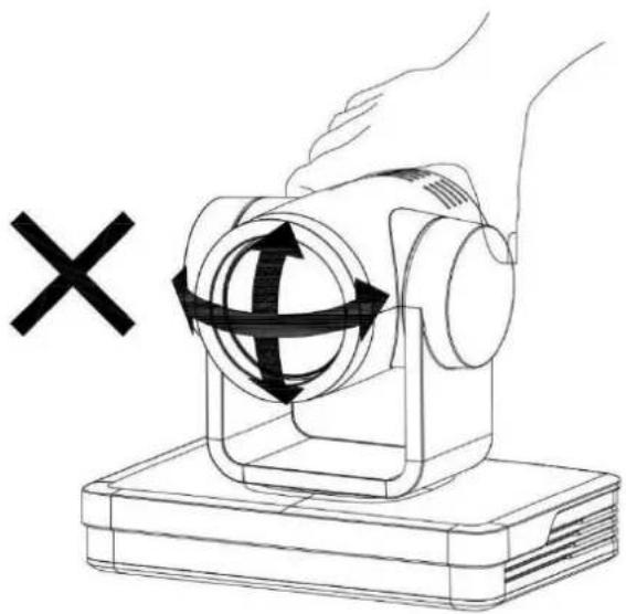
Do not rotate the lens and holder manually whether the camera is power on or off. Doing so may damage the camera and result in self-check failure and inability to start the camera.
natural_image
Illustration of a hand operating a mechanical device with a circular component and directional arrows, no text or symbols present.This manual introduces functions, installations and operations for this PTZ camera in detail. Please read carefully before installation and use.
1. Caution
1.1 Avoid damage to product caused by heavy pressure, strong vibration or immersion during transportation, storage and installation.
1.2 Housing of this product is made of organic materials. Do not expose it to any liquid, gas or solids which may corrode the shell.
1.3 Do not expose the product to rain or moisture.
1.4 To prevent the risk of electric shock, do not open the case. Installation and maintenance should only be carried out by qualified technicians.
1.5 Do not use the product beyond the specified temperature, humidity or power supply specifications.
1.6 Wipe it with a soft, dry cloth when cleaning the camera lens. Wipe it gently with a mild detergent if needed. Do not use strong or corrosive detergents to avoid scratching the lens and affecting the image;
1.7 This product contains no parts which can be maintained by users themselves. Any damage caused by dismantling the product by user without permission is not covered by warranty.
2. Electrical Safety
Installation and use of this product must strictly comply with local electrical safety standards.
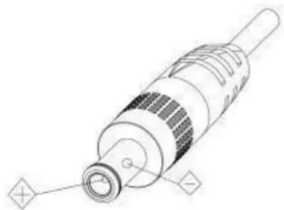
The power supply of the product is ±12V , the max electrical current is 2A.
natural_image
Technical line drawing of a mechanical component with no visible text or symbols3. Installation
1.1 Do not rotate the camera head violently, otherwise it may cause mechanical failure;
1.2 This product should be placed on a stable desktop or other horizontal surface. Do not install the product obliquely, otherwise it may display inclined image;
1.3 Ensure there are no obstacles within rotation range of the holder.
1.4 Do not power on before completely installation.
4. Magnetic Interference
Electromagnetic fields at specific frequencies may affect the video image. This product is Class A. It may cause radio interference in household application. Appropriate measure is required.
on. Appropriate measure is required.
Contents
1. Camera Installation....1
1.1 Camera Introduction....1
1.2 Interfaces and Connection ...... 2
1.3 Mounting Brackets....2
2. Product Overview ...... 7
2.1 Dimensions....7
2.2 Accessory....7
2.3 RS-232 Interface....8
2.4 Rotary Dial Switch 9
2.5 Main Features ...... 9
2.6 Specifications....10
3. Remote Control....13
3.1 Match Code for Wireless Remote Control....13
3.2 Keys Introduction for IR Remote Control....13
3.3 Menu Introduction....17
4. Network Configuration....18
4.1 Network Connection....18
4.2 IE Login....19
4.3 Streaming....19
4.4 Software Upgrade 21
4.5 Webpage Configuration for Human Detection....22
5. Serial Communication Control....23
5.1 VISCA Protocol Return Command....23
5.2 VISCA Protocol Control Command 23
5.3 VISCA Protocol Inquiry Command....26
5.4 PELCO-D Protocol Command List....27
5.5 PELCO-P Protocol Command List....28
6. Maintenance and Troubleshooting....29
6.1 Maintenance....29
6.2 Troubleshooting....29
7. Copyright Statement....30
1. Camera Installation
1.1 Camera Introduction
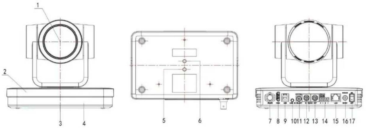
Figure 1.1 Interface of SU (standard) Model
- Camera Lens
- Camera Base
- Remote Control Receiving Indicator
- Infrared Receiver
- Tripod Screw Hole
- Screw Hole for Tripod
- SDI Output Interface
- HDMI
-
USB 3.0
-
Audio Input Interface(LINE-IN)
- Rotary Dial Switch
- RS232 Input Interface (input)
- RS232 Output Interface (Output)
- RS422 Compatible with RS485 Interface
- LAN Port
- Power Input Socket (DC12V)
- Power Switch Button
1.2 Interfaces and Connection
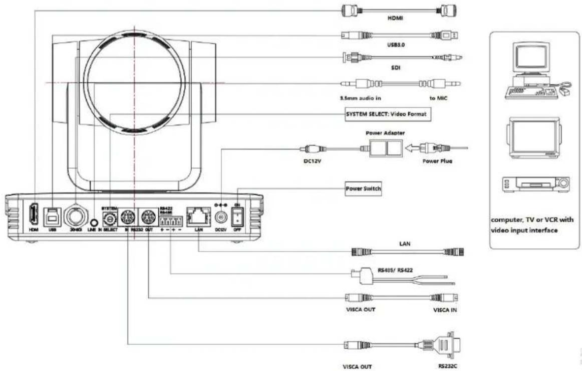
Figure 1.3 Wiring Diagram
1) After power on and self-check, the camera will automatically return to the preset 0 position if it's pre-set.
2) The default address for the IR remote control is 1#. If the menu is restored to factory defaults, the remote control default address will restore to 1#.
1.3 Mounting Brackets
Note:
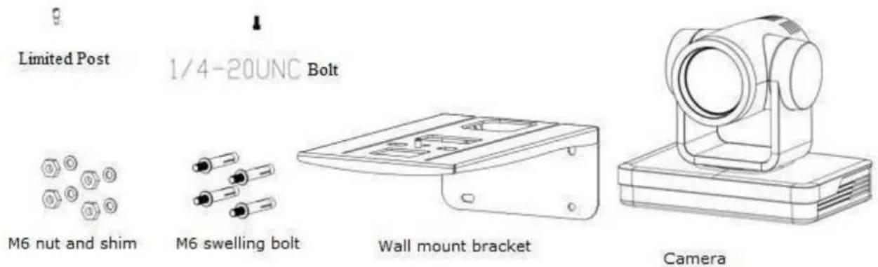
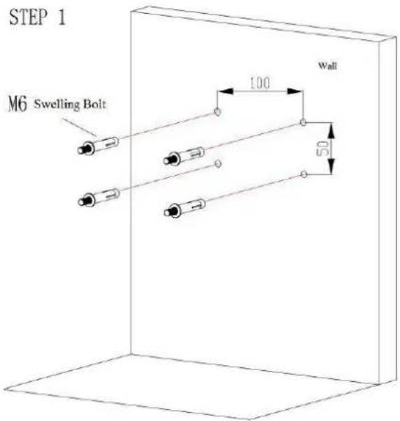
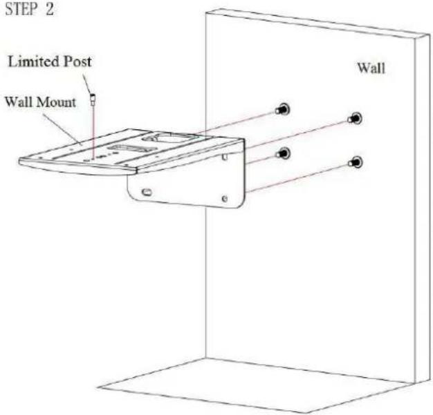
Ceiling or wall mounting brackets can only be mounted on template and concrete wall.
For safety reason, plasterboard is not recommended.
1) Wall Mounting:
STEP 2
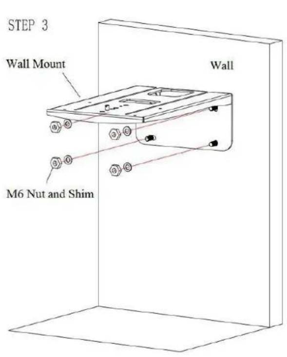
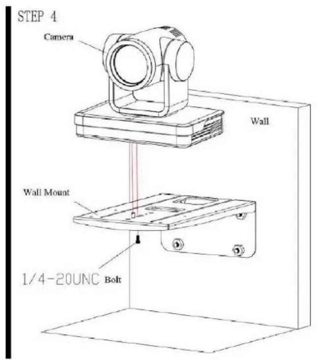
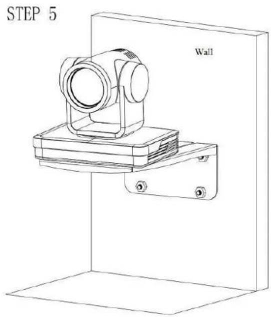
2) Ceiling Mounting
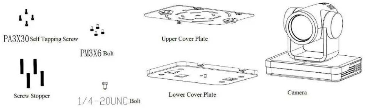
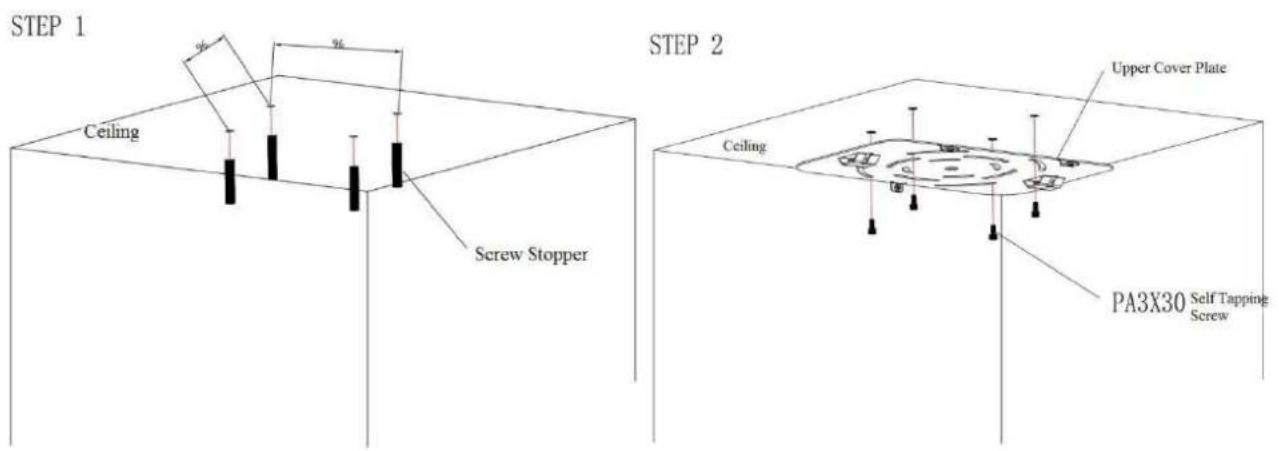
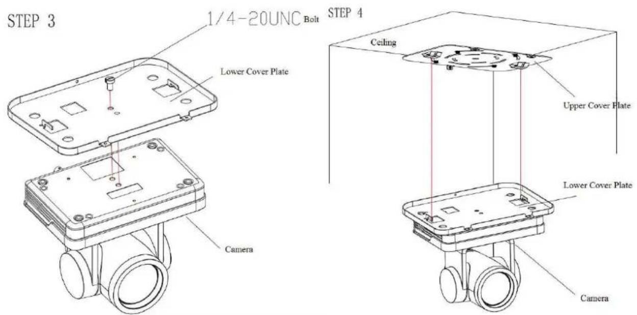
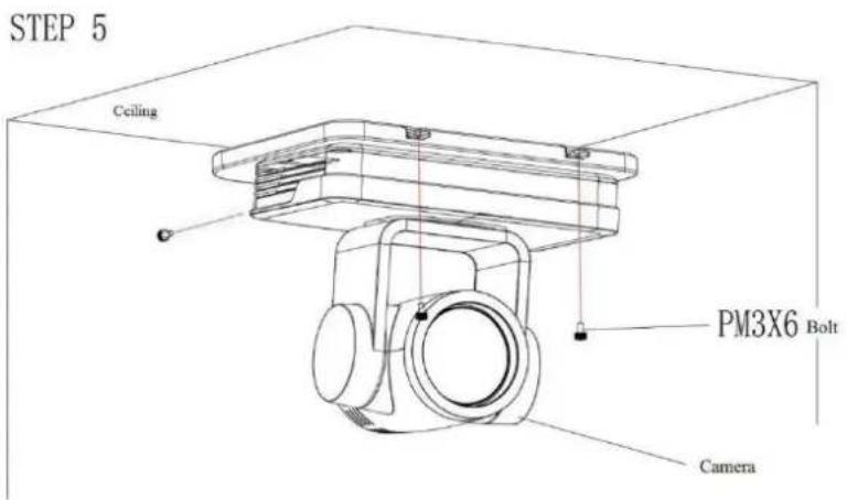
2. Product Overview
2.1 Dimensions
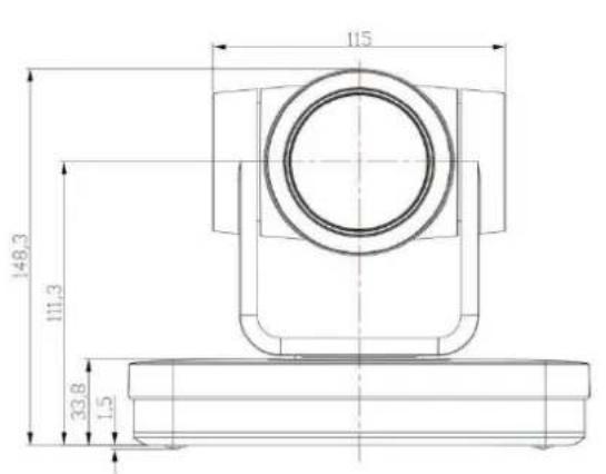
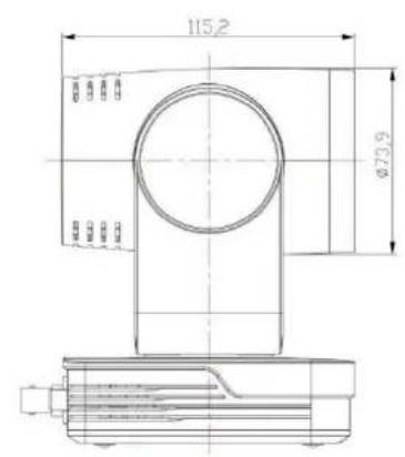
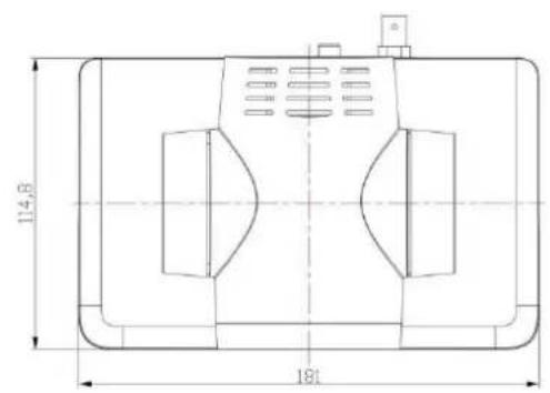
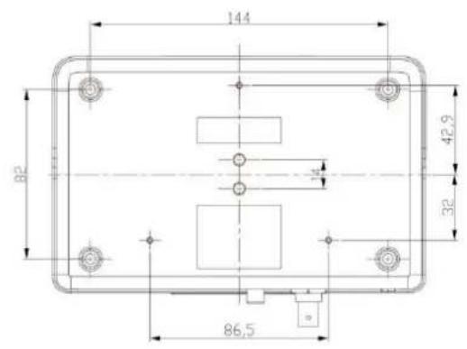
Figure 2.2 Product Dimensions
2.2 Accessory
Please check below standard and optional accessories when unpacking the box.
| Standard Accessory | Optional Accessory |
| Power adapter | Wireless Remote Control |
| RS232 Cable | Ceiling Mount |
| User Manual | Wall Mount |
| USB3.0 Cable | Infrared Remote Control |
| Warranty Card |
2.3 RS-232 Interface
1). RS-232 Interface Definition
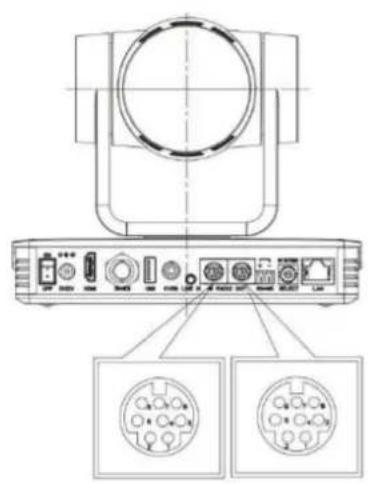
Connection to PC or Camera Controller
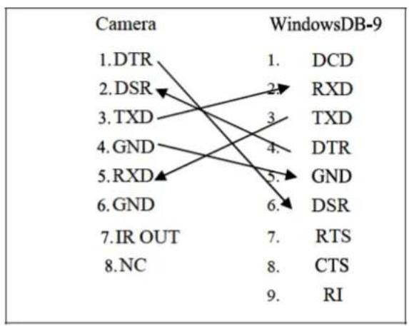
flowchart
graph TD
    A["1. DTR"] --> B["2. DSR"]
    A --> C["3. TXD"]
    A --> D["4. GND"]
    A --> E["5. RXD"]
    A --> F["6. GND"]
    A --> G["7. IR OUT"]
    A --> H["8. NC"]
    I["1. DCD"] --> J["2. RXD"]
    I --> K["3. TXD"]
    I --> L["4. DTR"]
    I --> M["5. GND"]
    I --> N["6. DSR"]
    O["7. RTS"] --> P["8. CTS"]
    O --> Q["9. RI"]

flowchart
graph LR
    A["Camera RS232 in"] --> B["MD8M"]
    B --> C["DB9F"]
    C --> D["PC / Camera Controller RS232 interface"]
2). RS232 Mini-DIN 8-pin: Port Definition
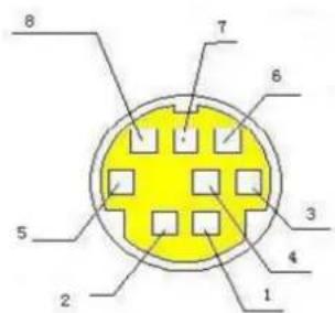
| NO. | Port | Definition |
| 1 | DTR | Data Terminal Ready |
| 2 | DSR | Data Set Ready |
| 3 | TXD | Transmit Data |
| 4 | GND | Signal Ground |
| 5 | RXD | Receive Data |
| 6 | GND | Signal Ground |
| 7 | IR OUT | IR Commander Signal |
| 8 | NC | No Connection |
3). RS232 (DB9) Port Definition
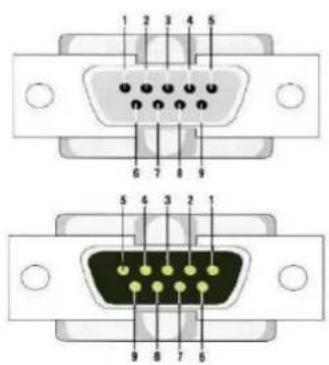
| NO. | Port | Definition |
| 1 | DCD | Data Carrier Detect |
| 2 | RXD | Receive Data |
| 3 | TXD | Transmit Data |
| 4 | DTR | Data Terminal Ready |
| 5 | GND | System Ground |
| 6 | DSR | Data Set Ready |
| 7 | RTS | Request to Send |
| 8 | CTS | Clear to Send |
| 9 | RI | Ring Indicator |
4). VISCA networking as shown below:
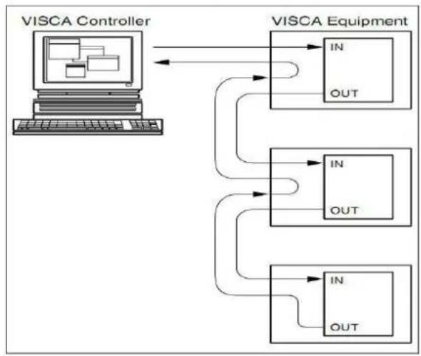
flowchart
graph TD
    A["VISCA Controller"] --> B["VISCA Equipment"]
    B --> C["IN OUT"]
    B --> D["IN OUT"]
    B --> E["IN OUT"]
    C --> F["Out"]
    D --> G["Out"]
    E --> H["Out"]
Camera cascade connection
Camera 1 Camera 2
1.DTR 1.DTR
2.DSR 2.DSR
3.TXD 3.TXD
4.GND 4.GNE
5.RXD 5.RXD
6.GND 6.GND
7.IR OUT 7.OPEN
- NC 8.OPEN
2.4 Rotary Dial Switch
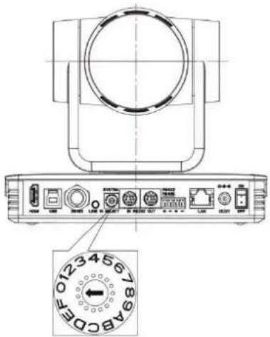
0: Video Format 1080P60 8: Video Format 720P59.94
1: Video Format 1080P50 9: ----
2: Video Format 1080P30 A: ----
3: Video Format 1080P25 B: ----
4: Video Format 720P60 C: ----
5: Video Format 720P50 D: ----
6: VideoFormat 1080P59.94 E: ----
7: Video Format 1080P29.97 F: ----
Note: After turning the dial to modify the video format, power off and restart to take effect. After turning the dial to F, power off and restart, the menu will display the video format.
2.5 Main Features
This camera provides optimized functions, superior performance and rich video output interfaces. Featuring advanced ISP processing algorithms, it offers vivid high resolution video with a excellent depth and color rendition. It supports H.264/H.265 encoding for fluent motion video and clarity under low bandwidth conditions.
● Full HD Resolution: 1/2.8 inch high quality CMOS sensor. Resolution is up to 1920x1080 with frame rate up to 60 fps.
● 20X Optical Zoom Lens
● Leading Auto Focus Technology: Fast, accurate and stable auto focusing technology.
● Low Noise and High SNR: Super high SNR image is achieved with low noise CMOS. Advanced 2D/3D noise reduction technology further reduces the noise while ensuring high image clarity.
● Multiple video output interfaces: HDMI, SDI, CVBS, LAN.
Simultaneously output audio and video signal via HDMI, SDI and LAN. LAN interface support POE, USB 3.0 support dual code stream, SDI support transmission up to 100m under 1080P60 format
- Multiple Audio/Video Compression Standards: Support H.264/H.265 video compression, up to 1920×1080 resolution 60 fps; support AAC, MP3 and G.711A audio compression, 8000, 16000, 32000, 44100, 48000 sampling frequency
- USB3.0 Support Dual Coding Stream: Support main stream and sub-stream, and simultaneous output; support YUY2, MJPEG, H.264, NV12, H.265 video coding format
● Built-in Gravity Sensor: support PTZ auto-flip function and easy installation.
- Multiple Network Protocol: support ONVIF, GB/T28181, RTSP, RTMP, VISCA OVER IP, IP VISCA, RTMPS,SRT protocols; Support RTMP push mode, easy to be connected to streaming server (Wowza, FMS); Support RTP multicast mode;
● Control Interface: RS422 is compatible with RS485, RS232-IN, RS232-OUT, and the RS232 interface supports cascading.
- Multiple Control Protocol: Support VISCA, PELCO-D, PELCO-P protocols; Support automatic identification protocols.
- Quiet Pan / Tilt Movement: with high accuracy step driving motor, camera can pan / tilt extremely quiet and smooth.
- Various remote controls: Users can choose infrared remote control or wireless remote control according to the environmental conditions used. The 2.4G wireless remote control is not affected by angle, distance, and infrared interference. Support the remote control signal transparent transmission function, which is convenient for back-end equipment to use.
● AI Human Detection: Built-in high-speed processor and advanced image processing and analysis algorithms, users can choose real-time tracking and regional tracking according to the environment.
- Multiple Application: Online-education, Lecture Capture, Webcasting, Video conferencing, Tele-medicine, Unified Communication, Emergency command and control systems, etc.
2.6 Specifications
| Camera Parameter | |
| Optical Zoom | 20X |
| Focus | 5.2 -- 98mm |
| FOV | 3.2° (N)56° (W) |
| Aperture Value | F1.5 -- F3.0 |
| Effective Pixels | 2.07, 1/2.8-inch high-quality CMOS sensor |
| Video Format | HDMI/SDI: 1080P60, 1080P50, 1080P30, 1080P25, 720P60, 720P50,1080P59.94, 1080P29.97, 720P59.94;USB3.0: main stream: YUY2/NV12:1920×1080/1280×720/1024×576/800×600/800×448/640×360/640×480/480×270/320×180@30/25/20/15/10/5fps;MJPG/H264:1920×1080/1600×896/1280×720/1024×576/960×540/800×600/800×448/720×576/720×480/640×360/640×480/480×270/352×288/320×240@30/25/20/15/10/5fps;Sub-stream: YUY2/NV12:1920×1080/1280×720/1024×576/800×600/800×448/640×360/640×480/480×270/320×180@30/25/20/15/10/5fps;MJPG/H264:1920×1080/1600×896/1280×720/1024×576/960×540/800×600/800×448/720×576/720×480/640×360/640×480/480×270/352×288/320×240@30/25/20/15/10/5fps; |
| Minimum illumination | 0.5Lux(F1.8, AGC ON) |
| DNR | 2D & 3D |
| AWB | Automatic, manual, one-key white balance, specified color temperature |
| Focus mode | Automatic, manual, one-key focus |
| Exposure mode | Auto, manual, shutter priority, aperture priority, brightness priority |
| Iris value | F1.8 -- F11, CLOSE |
| Shutter Speed | 1/25 -- 1/10000 |
| BLC | on/off |
| Dynamic range | Off, 1 -- 8 |
| Image adjustment | Brightness, chroma, saturation, contrast, sharpness, black and white mode, gamma curve |
| SNR | ≥50dB |
| AI Function & Performance | |
| Real-Time Tracking | Maximum Tracking Range: 6-7 meters. Support speakers to walk at a speed of 3-4 meters |
| Regional Tracking | Maximum Tracking Region: 4. Support set the region within horizontal -170°~+170° and vertical -30°~+90° |
| Interface | |
| Product Interface | HDMI, LAN (POE), USB3.0 (Type B, Compatible with USB2.0), SDIA-IN, RS232-IN, RS232-OUT, RS422 (Compatible with RS485), Rotary Switch DC12V Power |
| Video Encoding Format | LAN interface: Support main stream and sub-stream H.265, H.264USB3.0 Interface: Main stream support YUY2, MJPG, H264, NV12 |
| Audio Input Interface | Dual channel 3.5mm linear input |
| Audio Output Interface | HDMI, SDI, LAN, USB3.0 |
| Audio Compression | AAC, MP3, G.711A |
| LAN Interface | 10M/100M/1000M adaptive Ethernet port, support POE power supply, support audio and video output |
| Network Protocol | RTSP, RTMP, ONVIF, GB/T28181, VISCA OVER IP, IP VISCA, RTMPS, SRTSupport remote upgrade, remote restart, remote reset |
| Control Interface | RS232-IN, RS232-OUT, RS422 compatible with RS485 |
| Serial Communication Protocol | VISCA/Pelco-D/Pelco-P; support baud rate 115200/38400/9600/4800/2400 |
| USB Communication Protocol | UVC (video communication protocol), UAC (audio communication protocol) |
| Power Interface | HEC3800 Power socket (DC12V) |
| Power Adapter | Input AC110V-AC220V; output DC12V/2.5A |
| Input Voltage | DC12V±10% |
| Input Currency | <1A |
| Consumption | <12W |
| PTZ | |
| Pan rotation | -170° -- +170° |
| Tilt rotation | -30° -- +90° |
| Pan speed | 0.1°/s -- 100°/s |
| Tilt speed | 0.1°/s -- 45°/s |
| Preset speed | Pan: 100°/s, Tilt: 45°/s |
| Preset quantity | Maximum 255 preset positions can be set(10 via remote controls) |
| Other Parameter | |
| Storage temperature | -10°C -- +70°C |
| Storage humidity | 20% -- 95% |
| Working temperature | -10°C -- +50°C |
| Working humidity | 20% -- 80% |
| Dimension | 181mm×115mm×149mm |
| Weight | 1.15kg |
| Environment | Indoor |
| Accessory | |
| Standard accessory | Power adapter, RS232 control line, USB3.0 connection line, remote control, manual, warranty card & certificate |
| Optional accessory | Ceiling mounting bracket, wall mounting bracket |
3. Remote Control
3.1 Match Code for Wireless Remote Control
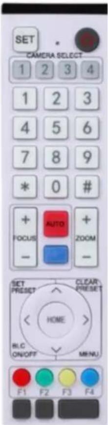
One to One Code Matching:
Press the SET and * keys together for 3 seconds. LED indicator will start flashing. When the camera receives the signal and powers on, LED indicator will turn off if the code matched successfully. The camera can be controlled by this wireless remote control only after successful one-to-one code pairing. Otherwise, please clear the remote control's code matching or use another remote control to pair with the camera again.
If one-to-one code matching fails, the red LED light flashes for 20 seconds then turns off, and the camera will stop code matching and enter sleep mode. Press any key to wake up the camera and re-match code.
Note: After successful code matching, please select the camera address to control it.
Clearing Code:
Press the SET and * keys together for 3 seconds. LED indicator will start flashing, and the camera will power off and on. The LED indicator will turn off once code is cleared.
Sleep Mode and Wake Up:
Press any key to wake up the camera from sleep mode.
3.2 Keys Introduction for IR Remote Control
1). In this manual, "press the key" means a click rather than a long-press, and a special note will be given if a long-press for more than one second is required.
2). When a key-combination is required, do it in sequence. For example, “【*】+【#】+【F1】” means press“【*】” first and then press“【#】” and last press“【F1】”.
1. Standby Key
The camera enters standby mode if long press 3s on standby key;
Long press 3s again on the standby key, the camera will self-check again and return to HOME position (If preset 0 position is set, the camera will return to preset 0 position).
2. Camera Selection
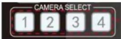
3. Focus Control
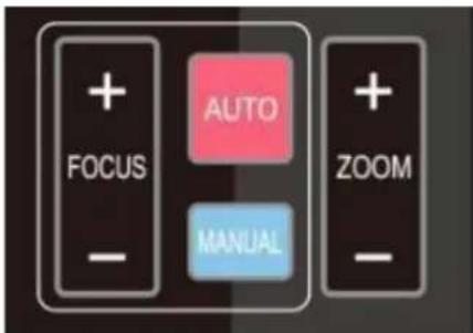
4. Zoom Control
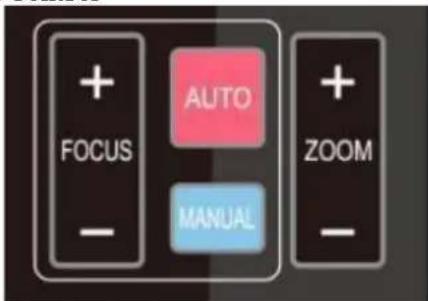
Select the camera address to control.
Auto: auto focus mode
Manual: manual focus mode
Focus + (near):Press 【FOCUS +】 key (Valid only in manual focus mode)
Focus - (far): Press 【FOCUS -】 key (Valid only in manual focus mode)
Press and hold the keys, the action of focus will keep continue and stop as soon as the key is released.
Press and hold the keys, the action of focus will keep continue and stop as soon as the key is released.
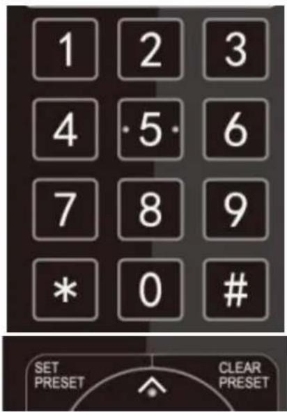
5. Set and Clear Presets
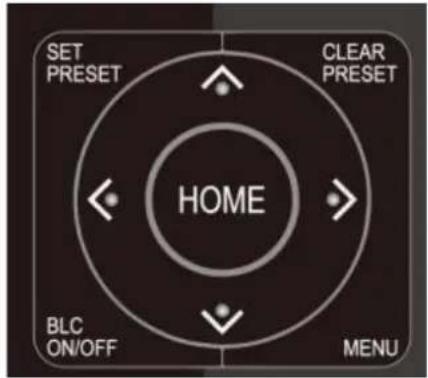
6. Pan/Tilt Control
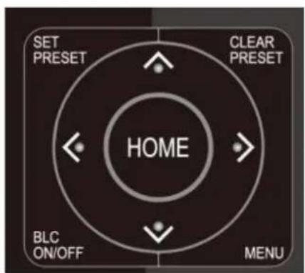
7. Menu Setting
Set Preset: press 【 SET PRESET 】 button, and then press the number key 0-9 to set preset positions.
Note: 10 presets via remote control.
Call Preset: Press a number key 0-9 directly to call a preset position.
Clear Preset: press 【CLEAR PRESET】 button, and then press the number key 0-9 to clear preset positions.
Note : press the【#】 key three times continually to clear all presets.
Up: press ▲ Down: press ▼ Left: press ◀ Right: press ▶ Back to middle position: press 【HOME】
Press and hold the up/down/left/right key, the pan/tilt movements will keep running, from slow to fast, until it runs to the endpoint; stop as soon as the key is released.
【MENU】: Open / close the OSD menu
【HOME】: Camera lens back to the middle position; Confirm button; Enter next menu
8. Camera Remote Control Address Setting
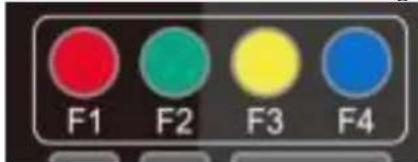
【*】+【#】+【F1】:Camera Address No.1
【*】+【#】+【F2】:Camera Address No. 2
【*】+【#】+【F3】:Camera Address No. 3
Note: If the address of former remote control is not address 1 but another one from 2, 3, 4, the corresponding camera address will restore to address 1 when all parameters are restored to factory default. User should change the remote control address to address 1.
10. Shortcut Keys of AI Functions
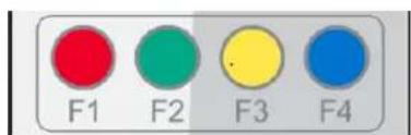
【F1】: Turn off AI Human Detection
【F2】: Turn on AI Human Detection
【F3】: Toggle between real time tracking mode and region tracking mode
【F4】: Chang tracking target on real tracking mode
3.3 Menu Introduction
Note: The modification valid only if exit the menu before save and power off.
1). Menu Control
【MENU】: Enter / exit the OSD menu or return to the previous menu
【HOME】: Enter next menu
4.1 Network Connection
Direct connection: Connect the camera and computer by network connecting cable.
Internet connection mode: Connect the camera to Internet by Router or Switcher and user can login the device by browser web page.
Note: Please do not put the power cable and network cable in places where can be easily touched, to prevent video unstable signal transmission due to poor contact of cables.
The computer must have the network segment where the camera IP address belongs to. The device will not be accessible if without the segment.
The camera default IP address is 192.168.5.163, segment 5 must be added in the computer.
Firstly open the window of Local Area Connection Properties on computer, select the “Internet protocol version 4(TCP/IPv4)”. Double click or click the property “Internet” protocol version 4 (TCP/IPv4) to enter into the Internet Protocol Version 4(TCP/IPv4) Properties window; select “Advanced” to enter into the Advanced TCP/IP Setting and add IP and subnet mask. Click the “Confirm” to finish the adding of IP segment. User can add the corresponding network segment according to the revised IP address of the camera.
Note: The IP address to be added cannot be same with that of other computers or devices. The existence of this IP address needs to be verified before adding.
To verify whether the network segment has been successfully added, click the "Start" and select "Operation" to input cmd, then click CONFIRM and open DOS command window, ping 192.168.5.26 and press Enter key to display information as shown below:
![Administrator: C:\Windows\system32\cmd.exe Microsoft Windows [Version 10.0.19042.1466] (c) Microsoft Corporation. All rights reserved. C:\Users\Administrator>ping 192.168.5.163 Pinging 192.168.5.163 with 32 bytes of data: Reply from 192.168.5.163: bytes=32 time<1ms TTL=64 Reply from 192.168.5.163: bytes=32 time<1ms TTL=64 Reply from 192.168.5.163: bytes=32 time<1ms TTL=64 Reply from 192.168.5.163: bytes=32 time<1ms TTL=64 Ping statistics for 192.168.5.163: Packets: Sent = 4, Received = 4, Lost = 0 (0% loss), Approximate round trip times in milli-seconds: Minimum = 0ms, Maximum = 0ms, Average = 0ms C:\Users\Administrator>](/content/2026/05/958388/images/f0779c8efbb88f3b855d3f33c9af95f3e71e5f5747d16d4ed38d0ce0447b2118.jpg)
After camera power on and self-check, follow the steps above to verify network connection. Open DOS command window, ping 192.168.5.163 and press Enter key.
![Administrator: C:\Windows\system32\cmd.exe Microsoft Windows [Version 10.0.19042.1466] (c) Microsoft Corporation. All rights reserved. C:\Users\Administrator>ping 192.168.5.163 Pinging 192.168.5.163 with 32 bytes of data: Reply from 192.168.5.163: bytes=32 time<1ms TTL=64 Reply from 192.168.5.163: bytes=32 time<1ms TTL=64 Reply from 192.168.5.163: bytes=32 time<1ms TTL=64 Reply from 192.168.5.163: bytes=32 time<1ms TTL=64 Ping statistics for 192.168.5.163: Packets: Sent = 4, Received = 4, Lost = 0 (0% loss), Approximate round trip times in milli-seconds: Minimum = 0ms, Maximum = 0ms, Average = 0ms C:\Users\Administrator>](/content/2026/05/958388/images/cbfb2cdad5a48665623a043de736f8bcd431dc98568538700402b805989c724d.jpg)
4.2 IE Login
1) Client Login
Input the default IP address 192.168.5.163 in the browser and click Enter button to enter into Web Client login page. User can login as administrator and normal user. If login as administrator (Default User name/Password: admin), users can preview, playback, and set configuration in the Web Client; If login in as normal user (Default User name/Password:user1 or user2), users can only preview, playback and logout, no option for configuration.
Note: Web access support IE based browsers: IE, 360 browsers and etc.
Chrome login is available after firmware update, but only support basic configuration and preview video, no functions of record video, voice volume, video capture and playback.
2). Download and Install Plug in for IE login
If it's the first time to login via IE browser, the login page will prompt "Playback plug-in is not installed, please download and install!" Click on this message, download and install MRWebXinstall.exe according to the information.
3). Web Page Login
After installing the plug-in, enter the user name and password, click login (the initial default user name and password are: "admin", you can change the user name and password after entering), enter the Web client management interface.
Enter user name and password (default user name and password: "admin").
Users can manage and change user name, password and etc.
4.3 Streaming
1). Video Stream Capture
Configurations -> Video Configure-> Video Encode
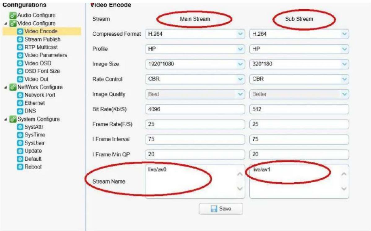
Configure the parameters according to the network environment.
Note: stream name live/av0 (live/ XXX)
For example:
The default IP address of the camera is 192.168.5.163. The way to obtain the RTSP video stream is as below rtsp://192.168.5.163:554/live/av0 (av0 main stream) rtsp://192.168.5.163:554/live/av1 (av1 sub stream)
The default IP address of the camera is 192.168.5.163. the way to obtain RTMP video stream is as below
rtmp://192.168.5.163:1935/live/av0 (av0 main stream)
rtmp://192.168.5.163:1935/live/av1 (av1 sub stream)
2). Push Video Stream
Configurations -> Video Configure-> Stream Publish
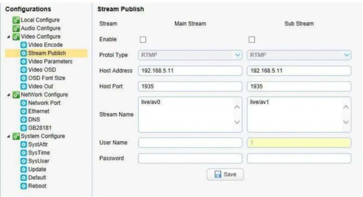
Push RTMP stream to public network server, the stream camera must be on the public network, otherwise it will fail to connect to server.
Host address: server address, which can be either a domain name or an IP address
Host port: server default port number
Stream name: live/test (live/ XXX)
Username and password: the username and password set by the server, or leave it empty
Access url: rtmp://host domain name: host port/live/xxx
Or (rtmp://host IP address: host port/live/xxx)
4.4 Software Upgrade
1). Log in to the web page and manage camera settings. The default page is preview interface, where users cam PTZ control, record video, preset camera positions and etc.
2). Configurations -> System Configure-> Update
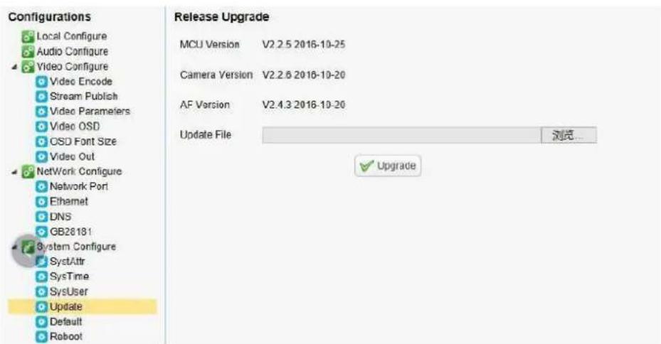
3). Click "browse" to select .mrg update file, then click upgrade button to finish software upgrade.
4). Camera reboots after completion of firmware update. It prompts with "successful upgrade."
Log in to check the firmware version to confirm successful software upgrade.
Then click "restore factory default", reboot and restore parameters to factory default (default IP 192.168.5.163, user name: admin; password admin).
4.5 Webpage Configuration for Human Detection
- After login, enter into the management interface and turn on Tracking below "Monocular Tracking"
- On the right top is PTZ control area, in which you can set the preset region of Regional Tracking. Interface is as below.
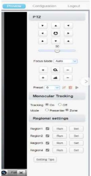
Regional Settings Steps (We take Region1 as an example):
-
On the PTZ Area, adjust image by clicking direction buttons to select one region.
-
After finishing region1 setting, click "Set" to complete the Region1 Tracking. Other region settings are same as region1 setting steps.
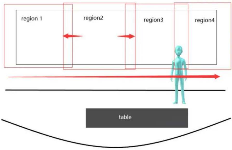
You can set 4 different regions, and minimum 2 regions. And the Regional Tracking settings can only be configured through the webpage.
Call out the regional tracking: Click "Run" of corresponding region on the "Regional settings" area.
-
Each preset preview image must be continuous from left to right and overlap when setting the tracking regions.
-
You need to tick next to the region number to save the setting location when you setting the region.
flowchart
graph TD
    A["region 1"] --> B["region2"]
    B --> C["region3"]
    C --> D["region4"]
    style A fill:#f9f,stroke:#333
    style B fill:#ccf,stroke:#333
    style C fill:#cfc,stroke:#333
    style D fill:#fcc,stroke:#333
    subgraph Region1
        A
        B
        C
        D
    end
    subgraph Region2
        B
        C
        D
    end
    subgraph Region3
        C
        D
    end
    subgraph Region4
        D
    end
    A -.-> B
    B -.-> C
    C -.-> D
    D -.-> E["Table"]
5. Serial Communication Control
Under normal working conditions, the device can be controlled through the RS232/RS485 interface. The RS232 serial port parameters are as follows:
Baud rate: 2400/4800/9600/38400/115200 bit/sec; start bit: 1 bit; data bit: 8 bits; stop bit: 1 bit; parity bit: none
After power on, the device first turns to the lower left and then back to the middle position. The zoom lens is pulled to the farthest position, and then pulled back to the most recent self-check to complete. If the device has saved No. 0 preset after initialization, the device will be set to No. 0 preset. At this point, the user can use the serial port command to control the device.
5.1 VISCA Protocol Return Command
| Ack/Completion Message | ||
| Command Packet | Note | |
| ACK | z0 41 FF | Returned when the command is accepted. |
| Completion | z0 51 FF | Returned when the command has been executed. |
z = Camera Address + 8
| Error Messages | ||
| Command Packet | Note | |
| Syntax Error | z0 60 02 FF | Returned when the command format is different or when a command with illegal command parameters is accepted |
| Command Not Executable | z0 61 41 FF | Returned when a command cannot be executed due to current conditions. For example, when commands controlling the focus manually are received during auto focus. |
5.2, VISCA Protocol Control Command
| Command | Function | Command Packet | Note |
| AddressSet | Broadcast | 88 30 0p FF | p: Address setting |
| IF_Clear | Broadcast | 88 01 00 01 FF | I/F Clear |
| CAM_Power | On | 8x 01 04 00 02 FF | Power ON/OFF |
| Off | 8x 01 04 00 03 FF | ||
| CAM_Zoom | Stop | 8x 01 04 07 00 FF | |
| Tele(Standard) | 8x 01 04 07 02 FF | ||
| Wide(Standard) | 8x 01 04 07 03 FF | ||
| Tele(Variable) | 8x 01 04 07 2p FF | p = 0(low) - 7(high) | |
| Wide(Variable) | 8x 01 04 07 3p FF | ||
| Direct | 8x 01 04 47 0p 0q 0r 0s FF | pqrs: Zoom Position | |
| CAM_Focus | Stop | 8x 01 04 08 00 FF | |
| Far(Standard) | 8x 01 04 08 02 FF | ||
| Near(Standard) | 8x 01 04 08 03 FF | ||
| Far(Variable) | 8x 01 04 08 2p FF | p = 0(low) - 7(high) | |
| Near (Variable) | 8x 01 04 08 3p FF | ||
| Direct | 8x 01 04 48 0p 0q 0r 0s FF | pqrs: Focus Position | |
| Auto Focus | 8x 01 04 38 02 FF | ||
| Manual Focus | 8x 01 04 38 03 FF | ||
| One Push mode | 8x 01 04 38 04 FF | ||
| Direct | 8x 01 04 47 0p 0q 0r 0s 0t 0u 0v 0w FF | pqrs: Zoom Position tuvw: Focus Position | |
| CAM_AFSensitivity | High | 8x 01 04 58 01 FF | Focus sensitivity Setting |
| Normal | 8x 01 04 58 02 FF | ||
| Low | 8x 01 04 58 03 FF | ||
| CAM_AFZone | Top | 8x 01 04 AA 00 FF | Focus Region Setting |
| Center | 8x 01 04 AA 01 FF | ||
| Bottom | 8x 01 04 AA 02 FF | ||
| ALL | 8x 01 04 AA 03 FF | ||
| CAM_WB | One Push mode | 8x 01 04 35 03 FF | |
| One Push Trigger | 8x 01 04 10 05 FF | One Push WB Trigger(Enabled during One Push WB mode) | |
| CAM_WB Mode | 8x 01 04 35 pq FF | pq = 00--33 WBMode | |
| CAM_AWBSensitivity | Low | 8x 01 04 A9 00 FF | WB Sensitivity Setting |
| Normal | 8x 01 04 A9 01 FF | ||
| High | 8x 01 04 A9 02 FF | ||
| CAM_RGain | Reset | 8x 01 04 03 00 FF | Manual Control of R Gain |
| Up | 8x 01 04 03 02 FF | ||
| Down | 8x 01 04 03 03 FF | ||
| Direct | 8x 01 04 43 00 00 0p 0q FF | pq: R Gain | |
| CAM_Bgain | Reset | 8x 01 04 04 00 FF | Manual Control of B Gain |
| Up | 8x 01 04 04 02 FF | ||
| Down | 8x 01 04 04 03 FF | ||
| Direct | 8x 01 04 44 00 00 0p 0q FF | pq: B Gain | |
| CAM_AE | Full Auto | 8x 01 04 39 00 FF | Automatic Exposure mode |
| Manual | 8x 01 04 39 03 FF | Manual Control mode | |
| Shutter priority | 8x 01 04 39 0A FF | Shutter Priority Automatic Exposure mode | |
| Iris priority | 8x 01 04 39 0B FF | Iris Priority Automatic Exposure mode | |
| Bright | 8x 01 04 39 0D FF | Bright mode | |
| CAM_Shutter | Reset | 8x 01 04 0A 00 FF | Shutter Setting |
| Up | 8x 01 04 0A 02 FF | ||
| Down | 8x 01 04 0A 03 FF | ||
| Direct | 8x 01 04 4A 00 00 0p 0q FF | pq: Shutter Position | |
| CAM_Iris | Reset | 8x 01 04 0B 00 FF | Iris Setting |
| Up | 8x 01 04 0B 02 FF | ||
| Down | 8x 01 04 0B 03 FF | ||
| Direct | 8x 01 04 4B 00 00 0p 0q FF | pq:Iris Position | |
| CAM_Gain Limit | Reset | 8x 01 04 0C 00 FF | Gain Limit Setting |
| Up | 8x 01 04 0C 02 FF | ||
| Down | 8x 01 04 0C 03 FF | ||
| Gain Limit | 8x 01 04 2C 0p FF | p: Gain Positon | |
| CAM_Bright | Reset | 8x 01 04 0D 00 FF | Bright Setting |
| Up | 8x 01 04 0D 02 FF | ||
| Down | 8x 01 04 0D 03 FF | ||
| Direct | 8x 01 04 4D 00 00 0p 0q FF | pq: Bright Positon | |
| CAM_ExpComp | On | 8x 01 04 3E 02 FF | Exposure Compensation ON/OFF |
| Off | 8x 01 04 3E 03 FF | ||
| Reset | 8x 01 04 0E 00 FF | Exposure Compensation Amount Setting | |
| Up | 8x 01 04 0E 02 FF | ||
| Down | 8x 01 04 0E 03 FF | ||
| Direct | 8x 01 04 4E 00 00 0p 0q FF | pq: ExpComp Position | |
| CAM_Back Light | On | 8x 01 04 33 02 FF | Back LightCompensation |
| Off | 8x 01 04 33 03 FF | ||
| CAM_WDRStrength | Reset | 8x 01 04 21 00 FF | WDR Level Setting |
| Up | 8x 01 04 21 02 FF | ||
| Down | 8x 01 04 21 03 FF | ||
| Direct | 8x 01 04 51 00 00 00 0p FF | p: WDR Level Positon | |
| CAM_NR | 2D | 8x 01 04 53 0p FF | P=0-7 0:OFF |
| 3D | 8x 01 04 54 0p FF | P=0-8 0:OFF | |
| CAM_Gamma | 8x 01 04 5B 0p FF | p = 0 - 4 0: Default 1: 0.45 2: 0.503: 0.55 4: 0.63 | |
| CAM_Low-Light Mode | ON | 8x 01 04 2D 01 FF | Low-Light Mode Setting |
| OFF | 8x 01 04 2D 00 FF | ||
| CAM_Gain | 8x 01 04 4C 00 00 0p 0q FF | pq: 0-15 | |
| CAM PresetSpeed | 8x 01 01 0p FF | p: 1-10 | |
| CAM_Flicker | OFF | 8x 01 04 23 00 FF | OFF |
| 50HZ | 8x 01 04 23 01 FF | 50HZ | |
| 60HZ | 8x 01 04 23 02 FF | 60HZ | |
| CAM_Aperture | Reset | 8x 01 04 02 00 FF | Aperture Control |
| Up | 8x 01 04 02 02 FF | ||
| Down | 8x 01 04 02 03 FF | ||
| Direct | 8x 01 04 42 00 00 0p 0q FF | pq: Aperture Gain | |
| CAM_Picture effect | B&W-Mode | 8x 01 04 63 04 FF | Picture effect Setting |
| OFF | 8x 01 04 63 00 FF | ||
| CAM_Memory | Reset | 8x 01 04 3F 00 pq FF | pq: Memory Number(=0 to 254)Corresponds to 0 to 9 on the Remote Commander |
| Set | 8x 01 04 3F 01 pq FF | ||
| Recall | 8x 01 04 3F 02 pq FF | ||
| CAM_LR_Reverse | On | 8x 01 04 61 02 FF | Image Flip Horizontal ON/OFF |
| Off | 8x 01 04 61 03 FF | ||
| CAM_PictureFlip | On | 8x 01 04 66 02 FF | Image Flip Vertical ON/OFF |
| Off | 8x 01 04 66 03 FF | ||
| CAM_ColorSaturation | Direct | 8x 01 04 49 00 00 0p 0q FF | p=0~7,q=0~f orpq: ColorSaturation Positon |
| CAM_IDWrite | 8x 01 04 22 0p 0q 0r 0s FF | pqrs: Camera ID (=0000 to FFFF) | |
| SYS_Menu | ON | 8x 01 04 06 06 02 FF | Turn on the menu screen |
| OFF | 8x 01 04 06 06 03 FF | Turn off the menu screen | |
| IR_Receive | ON | 8x 01 06 08 02 FF | IR(remote commander)receive On/Off |
| OFF | 8x 01 06 08 03 FF | ||
| CAM_SettingReset | Reset | 8x 01 04 A0 10 FF | Reset Factory Setting |
| CAM_Brightness | Direct | 8x 01 04 A1 00 00 0p 0q FF | pq: Brightness Position |
| CAM_Contrast | Direct | 8x 01 04 A2 00 00 0p 0q FF | pq: Contrast Position |
| CAM_Flip | OFF | 8x 01 04 A4 00 FF | Single Command For Video Flip |
| Flip-H | 8x 01 04 A4 01 FF | ||
| Flip-V | 8x 01 04 A4 02 FF | ||
| Flip-HV | 8x 01 04 A4 03 FF | ||
| CAM_VideoSystem | Set camera video system | 8x 01 06 35 00 0p FF | P: 0~E Video format0:1080P601:1080P502:Invalid Command3:Invalid Command4:720P605:720P506:1080P307:1080P25A:1080P59.94B:Invalid CommandC:720P59.94D:1080P29.97E:Invalid Command |
| Pan_tiltDrive | Up | 8x 01 06 01 VV WW 03 01 FF | VV: Pan speed 0x01 (low speed) to 0x18 (high speed)WW: Tilt speed 0x01 (low speed) to 0x14 (high speed)YYYY: Pan PositionZZZZ: Tilt Position |
| Down | 8x 01 06 01 VV WW 03 02 FF | ||
| Left | 8x 01 06 01 VV WW 01 03 FF | ||
| Right | 8x 01 06 01 VV WW 02 03 FF | ||
| Upleft | 8x 01 06 01 VV WW 01 01 FF | ||
| Upright | 8x 01 06 01 VV WW 02 01 FF | ||
| DownLeft | 8x 01 06 01 VV WW 01 02 FF | ||
| DownRight | 8x 01 06 01 VV WW 02 02 FF | ||
| Stop | 8x 01 06 01 VV WW 03 03 FF | ||
| AbsolutePosition | 8x 01 06 02 VV WW0Y 0Y 0Y 0Y 0Z 0Z 0Z 0Z FF | ||
| RelativePosition | 8x 01 06 03 VV WW0Y 0Y 0Y 0Y 0Z 0Z 0Z 0Z FF | ||
| Home | 8x 01 06 04 FF | ||
| Reset | 8x 01 06 05 FF | ||
| Pan-tilt LimitSet | Set | 8x 01 06 07 00 0W0Y 0Y 0Y 0Y 0Z 0Z 0Z 0Z FF | W:1 Up Right 0:Down LeftYYYY: Pan Limit Position(TBD)ZZZZ: Tilt Limit Position(TBD) |
| Clear | 8x 01 06 07 01 0W07 0F 0F 0F 07 0F 0F 0F FF |
5.3, VISCA Protocol Inquiry Command
| Command | Command Packet | Return Packet | Note |
| CAM_PowerInq | 8x 09 04 00 FF | y0 50 02 FF | On |
| y0 50 03 FF | Off(Standby) | ||
| CAM_ZoomPosInq | 8x 09 04 47 FF | y0 50 0p 0q 0r 0s FF | pqrs: Zoom Position |
| CAM_FocusAFModeInq | 8x 09 04 38 FF | y0 50 02 FF | Auto Focus |
| y0 50 03 FF | Manual Focus | ||
| y0 50 04 FF | One Push mode | ||
| CAM_FocusPosInq | 8x 09 04 48 FF | y0 50 0p 0q 0r 0s FF | pqrs: Focus Position |
| CAM_AFSensitivityInq | 8x 09 04 58 FF | y0 50 01 FF | High |
| y0 50 02 FF | Normal | ||
| y0 50 03 FF | Low | ||
| CAM_AFZoneInq | 8x 09 04 AA FF | y0 50 00 FF | Top |
| y0 50 01 FF | Center | ||
| y0 50 02 FF | Bottom | ||
| y0 50 03 FF | All | ||
| CAM_WBModeInq | 8x 09 04 35 FF | y0 50 pq FF | pq = WBMode |
| CAM_AWBSensitivityInq | 8x 09 04 A9 FF | y0 50 00 FF | Low |
| y0 50 01 FF | Normal | ||
| y0 50 02 FF | High | ||
| CAM_RGainInq | 8x 09 04 43 FF | y0 50 00 00 0p 0q FF | pq: R Gain |
| CAM_BGainInq | 8x 09 04 44 FF | y0 50 00 00 0p 0q FF | pq: B Gain |
| CAM_AEModeInq | 8x 09 04 39 FF | y0 50 00 FF | Full Auto |
| y0 50 03 FF | Manual | ||
| y0 50 0A FF | Shutter priority | ||
| y0 50 0B FF | Iris priority | ||
| y0 50 0D FF | Bright | ||
| CAM_ShutterPosInq | 8x 09 04 4A FF | y0 50 00 00 0p 0q FF | pq: Shutter Position |
| CAM_IrisPosInq | 8x 09 04 4B FF | y0 50 00 00 0p 0q FF | pq: Iris Position |
| CAM_Gain LimitInq | 8x 09 04 2C FF | y0 50 0p FF | p: Gain Positon |
| CAM_BrightPosInq | 8x 09 04 4D FF | y0 50 00 00 0p 0q FF | pq: Bright Position |
| CAM_ExpCompModeInq | 8x 09 04 3E FF | y0 50 02 FF | On |
| y0 50 03 FF | Off | ||
| CAM_ExpCompPosInq | 8x 09 04 4E FF | y0 50 00 00 0p 0q FF | pq: ExpComp Position |
| CAM_BacklightModeInq | 8x 09 04 33 FF | y0 50 02 FF | On |
| y0 50 03 FF | Off | ||
| CAM_WDRStrengthInq | 8x 09 04 51 FF | y0 50 0p FF | p: WDR Strength |
| CAM_NRLevel(2D) Inq | 8x 09 04 53 FF | y0 50 0p FF | P: 2DNRLevel |
| CAM_NRLevel(3D) Inq | 8x 09 04 54 FF | y0 50 0p FF | P: 3D NRLevel |
| CAM_FlickerModeInq | 8x 09 04 55 FF | y0 50 0p FF | p: Flicker Settings(0: OFF, 1: 50Hz, 2:60Hz) |
| CAM_ApertureInq | 8x 09 04 42 FF | y0 50 00 00 0p 0q FF | pq: Aperture Gain |
| CAM_PictureEffectModeInq | 8x 09 04 63 FF | y0 50 00 FF | Off |
| y0 50 04 FF | B&W | ||
| CAM_MemoryInq | 8x 09 04 3F FF | y0 50 0p FF | p: Memory number last operated. |
| SYS_MenuModeInq | 8x 09 06 06 FF | y0 50 02 FF | On |
| y0 50 03 FF | Off | ||
| CAM_LR_ReverseInq | 8x 09 04 61 FF | y0 50 02 FF | On |
| y0 50 03 FF | Off | ||
| CAM_PictureFlipInq | 8x 09 04 66 FF | y0 50 02 FF | On |
| y0 50 03 FF | Off | ||
| CAM_ColorSaturationInq | 8x 09 04 49 FF | y0 50 00 00 0p 0q FF | pq: Color Gain setting 0h (0) to Eh (127) |
| CAM_IDInq | 8x 09 04 22 FF | y0 50 0p FF | p: Gamma ID |
| IR_ReceiveInq | 8x 09 06 08 FF | y0 50 02 FF | On |
| y0 50 03 FF | Off | ||
| CAM_BrightnessInq | 8x 09 04 A1 FF | y0 50 00 00 0p 0q FF | pq: Brightness Position |
| CAM_ContrastInq | 8x 09 04 A2 FF | y0 50 00 00 0p 0q FF | pq: Contrast Position |
| CAM_FlipInq | 8x 09 04 A4 FF | y0 50 00 FF | Off |
| y0 50 01 FF | Flip-H | ||
| y0 50 02 FF | Flip-V | ||
| y0 50 03 FF | Flip-HV | ||
| CAM_GammaInq | 8x 09 04 5B FF | y0 50 0p FF | p: Gamma setting |
| CAM_Low-LightModeInq | 8x 09 04 2D FF | y0 50 00 FF | OFF |
| y0 50 01 FF | ON | ||
| CAM_VersionInq | 8x 09 00 02 FF | y0 50 ab cdmn pq rs tu vw FF | ab cd : vender ID ( 0220 )mn pq : model IDrs tu : ARM Versionvw : reserve |
| VideoSystemInq | 8x 09 06 23 FF | y0 50 0p FF | P: 0~E Video format0:1080P601:1080P502:Invalid Command3:Invalid Command4:720P605:720P506:1080P307:1080P25A:1080P59.94B:Invalid CommandC:720P59.94D:1080P29.97E:Invalid Command |
| Pan-tiltMaxSpeedInq | 8x 09 06 11 FF | y0 50 ww zz FF | ww: Pan Max Speed zz: Tilt Max Speed |
| Pan-tiltPosInq | 8x 09 06 12 FF | y0 50 0w 0w 0w 0w0z 0z 0z 0z FF | www: Pan Position zzzz: Tilt Position |
Note: [x] in the above table represents the address of the device to be operated, [y]=[x+8] .
5.4, PELCO-D Protocol Command List
| Function | Byte1 | Byte2 | Byte3 | Byte4 | Byte5 | Byte6 | Byte7 |
| Up | 0xFF | Address | 0x00 | 0x08 | Pan Speed | Tilt Speed | SUM |
| Down | 0xFF | Address | 0x00 | 0x10 | Pan Speed | Tilt Speed | SUM |
| Left | 0xFF | Address | 0x00 | 0x04 | Pan Speed | Tilt Speed | SUM |
| Right | 0xFF | Address | 0x00 | 0x02 | Pan Speed | Tilt Speed | SUM |
| Upleft | 0xFF | Address | 0x00 | 0x0C | Pan Speed | Tilt Speed | SUM |
| Upright | 0xFF | Address | 0x00 | 0x0A | Pan Speed | Tilt Speed | SUM |
| DownLeft | 0xFF | Address | 0x00 | 0x14 | Pan Speed | Tilt Speed | SUM |
| DownRight | 0xFF | Address | 0x00 | 0x12 | Pan Speed | Tilt Speed | SUM |
| Zoom In | 0xFF | Address | 0x00 | 0x20 | 0x00 | 0x00 | SUM |
| Zoom Out | 0xFF | Address | 0x00 | 0x40 | 0x00 | 0x00 | SUM |
| Focus Far | 0xFF | Address | 0x00 | 0x80 | 0x00 | 0x00 | SUM |
| Focus Near | 0xFF | Address | 0x01 | 0x00 | 0x00 | 0x00 | SUM |
| Stop | 0xFF | Address | 0x00 | 0x00 | 0x00 | 0x00 | SUM |
| Set Preset | 0xFF | Address | 0x00 | 0x03 | 0x00 | Preset ID | SUM |
| Clear Preset | 0xFF | Address | 0x00 | 0x05 | 0x00 | Preset ID | SUM |
| Call Preset | 0xFF | Address | 0x00 | 0x07 | 0x00 | Preset ID | SUM |
| Query Pan Position | 0xFF | Address | 0x00 | 0x51 | 0x00 | 0x00 | SUM |
| Query Pan Position Response | 0xFF | Address | 0x00 | 0x59 | Value High Byte | Value Low Byte | SUM |
| Query Tilt Position | 0xFF | Address | 0x00 | 0x53 | 0x00 | 0x00 | SUM |
| Query Tilt Position Response | 0xFF | Address | 0x00 | 0x5B | Value High Byte | Value Low Byte | SUM |
| Query Zoom Position | 0xFF | Address | 0x00 | 0x55 | 0x00 | 0x00 | SUM |
| Query Zoom Position Response | 0xFF | Address | 0x00 | 0x5D | Value High Byte | Value Low Byte | SUM |
5.5, PELCO-P Protocol Command List
| Function | Byte1 | Byte2 | Byte3 | Byte4 | Byte5 | Byte6 | Byte7 | Byte8 |
| Up | 0xA0 | Address | 0x00 | 0x08 | Pan Speed | Tilt Speed | 0xAF | XOR |
| Down | 0xA0 | Address | 0x00 | 0x10 | Pan Speed | Tilt Speed | 0xAF | XOR |
| Left | 0xA0 | Address | 0x00 | 0x04 | Pan Speed | Tilt Speed | 0xAF | XOR |
| Right | 0xA0 | Address | 0x00 | 0x02 | Pan Speed | Tilt Speed | 0xAF | XOR |
| Upleft | 0xA0 | Address | 0x00 | 0x0C | Pan Speed | Tilt Speed | 0xAF | XOR |
| Upright | 0xA0 | Address | 0x00 | 0x0A | Pan Speed | Tilt Speed | 0xAF | XOR |
| DownLeft | 0xA0 | Address | 0x00 | 0x14 | Pan Speed | Tilt Speed | 0xAF | XOR |
| DownRight | 0xA0 | Address | 0x00 | 0x12 | Pan Speed | Tilt Speed | 0xAF | XOR |
| Zoom In | 0xA0 | Address | 0x00 | 0x20 | 0x00 | 0x00 | 0xAF | XOR |
| Zoom Out | 0xA0 | Address | 0x00 | 0x40 | 0x00 | 0x00 | 0xAF | XOR |
| Stop | 0xA0 | Address | 0x00 | 0x00 | 0x00 | 0x00 | 0xAF | XOR |
| Focus Far | 0xA0 | Address | 0x01 | 0x00 | 0x00 | 0x00 | 0xAF | XOR |
| Focus Near | 0xA0 | Address | 0x02 | 0x00 | 0x00 | 0x00 | 0xAF | XOR |
| Set Preset | 0xA0 | Address | 0x00 | 0x03 | 0x00 | Preset ID | 0xAF | XOR |
| Clear Preset | 0xA0 | Address | 0x00 | 0x05 | 0x00 | Preset ID | 0xAF | XOR |
| Call Preset | 0xA0 | Address | 0x00 | 0x07 | 0x00 | Preset ID | 0xAF | XOR |
| Query Pan Position | 0xA0 | Address | 0x00 | 0x51 | 0x00 | 0x00 | 0xAF | XOR |
| Query Pan Position Response | 0xA0 | Address | 0x00 | 0x59 | Value High Byte | Value Low Byte | 0xAF | XOR |
| Query Tilt Position | 0xA0 | Address | 0x00 | 0x53 | 0x00 | 0x00 | 0xAF | XOR |
| Query Tilt Position Response | 0xA0 | Address | 0x00 | 0x5B | Value High Byte | Value Low Byte | 0xAF | XOR |
| Query Zoom Position | 0xA0 | Address | 0x00 | 0x55 | 0x00 | 0x00 | 0xAF | XOR |
| Query Zoom Position Response | 0xA0 | Address | 0x00 | 0x5D | Value High Byte | Value Low Byte | 0xAF | XOR |
5. Maintenance and Troubleshooting
6.1 Maintenance
1) Please power off the camera and disconnect the power adapter and socket, if it's not used for a long run.
2) Use soft cloth or tissue to clean the camera cover.
3) Wipe it with a soft, dry cloth when cleaning the camera lens. Wipe it gently with a mild detergent if needed. Do not use strong or corrosive detergents to avoid scratching the lens and affecting the video quality.
6.2 Troubleshooting
1) No video output
a. Check whether the camera power supply is connected, the voltage is normal, the power indicator is lit.
b. Whether the machine could do self-check after restarted.
c. Check whether the bottom of the DIP switch is the normal operating mode (see Table 2.2 and Table 2.3)
d. Check whether the video output cable or video display is normal
2) Image flickering issues
a. Check whether the video output cable or video display is normal
3) Video dithering when zoom-in or zoom-out
a. Check whether the camera installation position is solid
b. Whether there is shaking machine or objects around the camera
4) Remote control not works
a. Remote control address is set to 1 (if the machine is set back to the factory defaults, remote control addresses need to be back to 1 too)
b. Check whether the battery is installed on the remote controller or low.
c, Check the camera working mode is the normal operating mode (see Table 2.2 and Table 2.3)
d. Check the menu whether is closed, camera control through remote controller is only available after exiting the menu. If video output from LAN, menu will not be displayed, menu will automatically exists 30s later, and then it can be controlled by remote controller.
5) Serial port not works
a. Check whether the camera serial device protocol, baud rate, address is consistent
b. Check whether the control cable is connected properly
c. Check whether the camera working mode is the normal operating mode
6) Web pages cannot log in
a. Check if the camera outputs video normally by connecting directly to the screen.
b. Check whether the network cable is connected properly (Ethernet port yellow light flashes to indicate normal network cable connection)
c. Check whether your computer is added the segment and the segment is consistent with the IP address of the camera
d. Click "Start" and select "Run" and then type "cmd" in thecomputer; Click "OK" then turn on a DOS command window to enter ping 192.168.5.163. Press the Enter key to appear message as follows: Description network connection is normal
![Administrator: C:\Windows\system32\cmd.exe Microsoft Windows [Version 10.0.19042.1466] (c) Microsoft Corporation. All rights reserved. C:\Users\Administrator>ping 192.168.5.26 Pinging 192.168.5.26 with 32 bytes of data: Reply from 192.168.5.26: bytes=32 time=2ms TTL=64 Reply from 192.168.5.26: bytes=32 time<1ms TTL=64 Reply from 192.168.5.26: bytes=32 time<1ms TTL=64 Reply from 192.168.5.26: bytes=32 time<1ms TTL=64 Ping statistics for 192.168.5.26: Packets: Sent = 4, Received = 4, Lost = 0 (0% loss), Approximate round trip times in milli-seconds: Minimum = 0ms, Maximum = 2ms, Average = 0ms C:\Users\Administrator>](/content/2026/05/958388/images/9f9603f57bfef2bb99b4a9774a037dda7547e246c119d1b3a1db15610e5cbeb1.jpg)
6. Copyright Statement
All the contents in this manual and its copyright are owned by the company. No one is allowed to imitate, copy, or translate this manual without the company's permission. This manual contains no guarantee, standpoint expression or other implies in any form. Product specification and information in this manual is for reference only and subject to change without notice. All rights reserved. No reproducing is allowed without acknowledgement.
- Precaution
- Caution
- Electrical Safety
- Installation
- Magnetic Interference
- Contents
- Camera Installation....1
- Product Overview ...... 7
- Remote Control....13
- Network Configuration....18
- Serial Communication Control....23
- Maintenance and Troubleshooting....29
- Copyright Statement....30
- Camera Installation
- Camera Introduction
- Interfaces and Connection
- Mounting Brackets
- Product Overview
- Dimensions
- Accessory
- RS-232 Interface
- Rotary Dial Switch
- Main Features
- Remote Control
- Match Code for Wireless Remote Control
- One to One Code Matching:
- Clearing Code:
- Sleep Mode and Wake Up:
- Keys Introduction for IR Remote Control
- Standby Key
- Camera Selection
- Focus Control
- Zoom Control
- Set and Clear Presets
- Pan/Tilt Control
- Menu Setting
- Camera Remote Control Address Setting
- Shortcut Keys of AI Functions
- Menu Introduction
- Network Connection
- IE Login
- 1) Client Login
- 2). Download and Install Plug in for IE login
- 3). Web Page Login
- Streaming
- 1). Video Stream Capture
- 2). Push Video Stream
- Software Upgrade
- Webpage Configuration for Human Detection
- Serial Communication Control
- VISCA Protocol Return Command
- 5.2, VISCA Protocol Control Command
- 5.4, PELCO-D Protocol Command List
- 5.5, PELCO-P Protocol Command List
- Maintenance and Troubleshooting
- Maintenance
- Troubleshooting
- 1) No video output
- 2) Image flickering issues
- 3) Video dithering when zoom-in or zoom-out
- 4) Remote control not works
- 5) Serial port not works
- 6) Web pages cannot log in
- Copyright Statement
Brand : DVDO
Model : C4-1-NDI-W
Category : Security Camera