
DGS-F1210-10PS-E - Switch D-LINK - Free user manual and instructions
Find the device manual for free DGS-F1210-10PS-E D-LINK in PDF.


| Product Type | Managed Gigabit PoE+ Switch |
| Model | DGS-F1210-10PS-E |
| Brand | D-Link |
| Ports | 8 x 10/100/1000 Mbps PoE+ ports, 2 x Gigabit SFP slots |
| PoE Budget | 70W (up to 30W per port) |
| Switching Capacity | 20 Gbps |
| MAC Address Table | 8K entries |
| Dimensions (W x D x H) | 280 x 180 x 44 mm |
| Weight | 2.5 kg |
| Power Supply | 100-240V AC, 50-60Hz, internal power supply |
| Max Power Consumption | 96W (with PoE full load) |
| Cooling | Fanless |
| Management | Web UI, CLI, SNMP v1/v2c/v3, RMON |
| VLAN Support | 802.1Q VLAN, up to 256 VLANs |
| Layer 2 Features | STP, RSTP, MSTP, Link Aggregation, IGMP Snooping |
| Security | 802.1X, ACL, Port Security, DHCP Snooping |
| Operating Temperature | 0°C to 40°C |
| Storage Temperature | -10°C to 70°C |
| Humidity | 10% to 90% non-condensing |
| Maintenance | Clean with a soft dry cloth; disconnect power before cleaning |
| Safety | Keep away from water and heat sources; do not open the case |
| Spare Parts & Repairability | No user-serviceable parts; contact D-Link support for repairs |
| Warranty | Limited lifetime warranty (check local terms) |
| Standards Compliance | IEEE 802.3, 802.3u, 802.3ab, 802.3z, 802.3af/at |
Frequently Asked Questions - DGS-F1210-10PS-E D-LINK
User questions about DGS-F1210-10PS-E D-LINK
0 question about this device. Answer the ones you know or ask your own.
Ask a new question about this device
Download the instructions for your Switch in PDF format for free! Find your manual DGS-F1210-10PS-E - D-LINK and take your electronic device back in hand. On this page are published all the documents necessary for the use of your device. DGS-F1210-10PS-E by D-LINK.
USER MANUAL DGS-F1210-10PS-E D-LINK
Getting Started Guide For D-Link DGS-F1210 Series Smart Managed Switch
natural_image
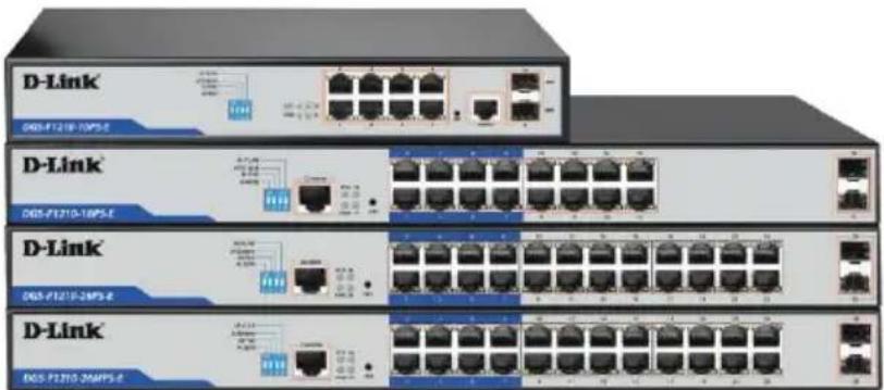
Diagram of a network switch device showing multiple Ethernet ports and connections (no text or labels)DGS-F1210-10PS-E
DGS-F1210-18PS-E
DGS-F1210-26PS-E
DGS-F1210-26MPS-E
natural_image
Stacked D-Link network equipment units with Ethernet ports and indicator lights (no visible text or labels beyond branding)1.1 Package Contents
The package contains the following items:
- PoE Switch
- Power Cord
• 19" Rack Mounting Kit - Quick Installation Guide
1.2 Safety Instructions

Use the following safety guidelines to ensure your own personal safety and to help protect your equipment from potential damage.
• The power cable should be disconnected from the mains during the installation process;
- Wear a grounded anti-static wrist band to avoid the build-up of static electricity;
- Power the product only from the type of external power source indicated on the electrical ratings label;
- Observe extension cable and power strip ratings. Make sure that the total ampere rating of all products plugged into the extension cable or power strip does not exceed 80 percent of the ampere ratings limit for the extension cable or power strip;
To avoid the risk of electric shock, do not open the Switch housing.
- Do not use damaged power cords. Do not modify power cables or plugs.
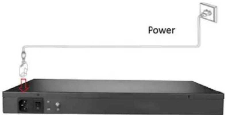
1.3 Connecting Power
Connect one end of the power cord to the rear of the Switch, and the other end to the mains power outlet.
1.4 Product Connection Diagram
Front Panel
(The number of RJ45 ports varies depending on model)
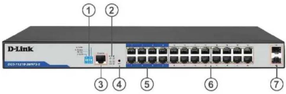
1 – Shortcut buttons (DIP Switches)
2 - LEDs
3 - Console port
4 - Reset button
5 - RJ45 PoE ports with Long Reach option (up to 250m)
6 - RJ45 PoE ports
7 - SFP ports
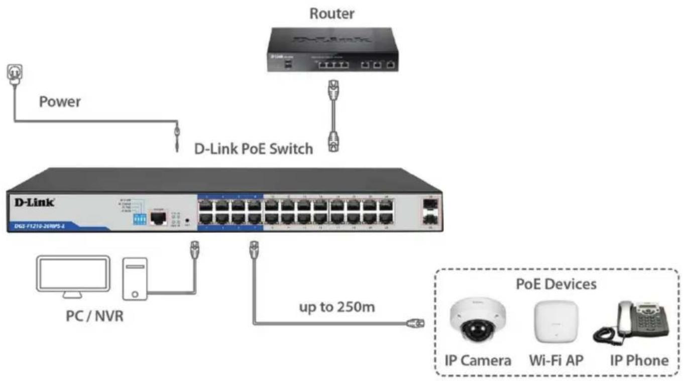
flowchart
graph TD
    A["Router"] -->|D-Link PoE Switch| B["D-Link"]
    B --> C["PC / NVR"]
    B --> D["Up to 250m"]
    D --> E["PoE Devices"]
    E --> F["IP Camera"]
    E --> G["Wi-Fi AP"]
    E --> H["IP Phone"]
1.5 Product Installation
The Switch can be installed on a desktop, shelf or mounted in a standard 19-inch Rack.
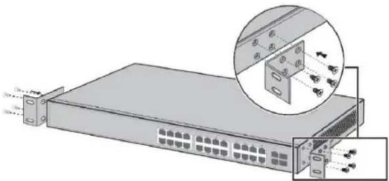
To install the Switch in a rack, attach the supplied mounting brackets to the side of the Switch and fasten the brackets to the sides of the Switch using the screws from the Switch mounting kit.
natural_image
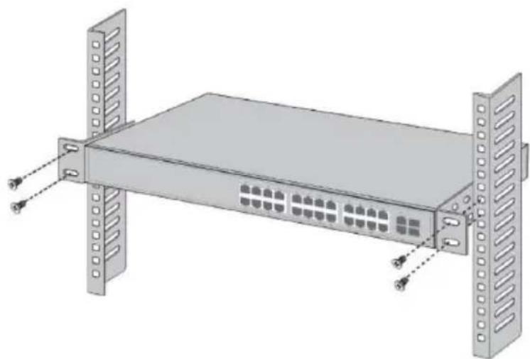
Diagram of a server rack with attached hardware components, showing internal wiring and mounting bracket (no text or labels)Align the brackets and rack holes. Fasten each bracket to the rack.
natural_image
3D rendering of a server rack with ventilation slots and mounting brackets (no text or symbols)1.6 Shortcut Buttons (DIP Switches)
Some Switch settings can be applied using the Shortcut Buttons (DIP Switches), without the need to log into the Switch interface.
| DIP Switch | Function when in ON position |
| AI QOS | Improve video data processing capabilities and improve the monitoring of Caton and Mosaic phenomena on the network. |
| AI Extend | Set ports 1 to 8 rate to 10Mbps, but the transmission distance increases up to 250 meters. |
| AI VLAN | Isolate RJ45 ports (1-8), (1-16), (1-24) from each other, suppress network storms and improve network performance. Uplink ports (9-10), (17-18), (25-26) continue to communicate with all ports. |
| AI PoE | Automatically restart a remote device by disabling and re-enabling PoE on the port if it detects the remote device has locked up (no incoming traffic). |
1.7 Web-based Management Interface
In order to login and configure the Switch via an Ethernet connection, the PC must have an IP address in the same range as the Switch. For example, if the Switch has an IP address of 192.168.254.1, the PC should have an IP address of 192.168.254.x (where x is a number between 2 and 254), with subnet mask of 255.255.255.0.
The default IP address of the Switch is 192.168.254.1
Open your web browser and enter http://192.168.254.1 in the address bar. Then press

The default username is "admin", the default password is "admin".
It is recommended to apply a secure strong password to "admin" account under System Settings >> User Management.
Brand : D-LINK
Model : DGS-F1210-10PS-E
Category : Switch