
Reference 311a - Receiver INFINITY - Free user manual and instructions
Find the device manual for free Reference 311a INFINITY in PDF.


| Product Type | Car Audio Mono Subwoofer Amplifier |
| Model | Reference 311a |
| Brand | Infinity |
| Power Output (RMS @ 4 ohms) | 116W x 1 channel |
| Power Output (RMS @ 2 ohms) | 312W x 1 channel |
| Dynamic Power @ 2 ohms | 347W |
| Frequency Response | 17Hz - 302Hz (-3dB) |
| Signal-to-Noise Ratio | 81dBA (reference 1W into 4 ohms) |
| Effective Damping Factor | 6.398 at 4 ohms |
| Maximum Input Signal | 6V |
| Maximum Sensitivity | 75mV |
| Output Regulation | 0.05dB at 4 ohms |
| Minimum Speaker Load | 2 ohms |
| Fuse Rating | 1 x 30A |
| Dimensions (L x W x H) | 12" x 11-7/16" x 2-11/16" |
| Weight | Approximately 5.5 lbs (estimate) |
| Input Type | Low-level (RCA) only |
| Output Type | Speaker-level terminals |
| Crossover Type | Low-pass only (fixed frequency via LP FREQ) |
| Dynamic Bass Optimizer (DBO) | Adjustable frequency (20Hz-80Hz) and boost (0-12dB) |
| Protection Features | Clip, Power, and Protect LEDs; thermal and DC offset protection |
Frequently Asked Questions - Reference 311a INFINITY
User questions about Reference 311a INFINITY
0 question about this device. Answer the ones you know or ask your own.
Ask a new question about this device
Download the instructions for your Receiver in PDF format for free! Find your manual Reference 311a - INFINITY and take your electronic device back in hand. On this page are published all the documents necessary for the use of your device. Reference 311a by INFINITY.
USER MANUAL Reference 311a INFINITY

Infinity®
referenceseries
311a,611a,
1211a,7521a,
7541a,5761a
instructions
Thank you for purchasing an Infinity® Reference Series amplifier. In order that we may better serve you should you require warranty service for your new amplifier, please retain your original purchase receipt and read the enclosed warranty information card.
INTRODUCTION
WARNING!
Playing loud music in an automobile can hinder your ability to hear traffic and permanently damage your hearing. We recommend listening at low or moderate levels while driving your car. Infinity accepts no liability for hearing loss, bodily injury or property damage resulting from the use or misuse of this product.
IMPORTANT
To get the best performance from your Reference Series amplifiers, we strongly recommend that installation be entrusted to a qualified professional. Although these instructions explain how to install Reference amplifiers in a general sense, they do not show specific installation methods that may be required for your particular vehicle. If you do not have the necessary tools or experience, do not attempt the installation yourself. Instead, please ask your authorized Infinity car audio dealer about professional installation.
INSTALLATION WARNINGS AND TIPS
• Always wear protective eyewear when using tools.
- Turn off the audio system and other electrical devices before you start. Disconnect the (−) negative lead from your vehicle's battery.
- Check clearances on both sides of a planned mounting surface before drilling any holes or installing any screws. Remember that the screws can extend behind the surface.
- At the installation sites, locate and make a note of all fuel lines, hydraulic brake lines, vacuum lines and electrical wiring. Use extreme caution when cutting or drilling in and around these areas.
- Before drilling or cutting holes, use a utility knife to remove unwanted fabric or vinyl to keep material from snagging in the drill bit.
- When routing cables, keep input-signal cables away from power cables and speaker wires.
- When making connections, make certain they are secure and properly insulated.
- If the amplifier's fuse must be replaced, use only the same type and rating as that of the original. Do not substitute another kind.
CHOOSING A LOCATION AND MOUNTING THE AMPLIFIER
Choose a mounting location in the trunk or cargo area where the amplifier will not be damaged by shifting cargo. Amplifier cooling is essential for proper amplifier operation. If the amplifier is to be installed in an enclosed space, make sure there is sufficient air circulation for the amplifier to cool itself.
When mounting the amplifier under a seat, ensure that it is clear of all moving seat parts and does not affect the seat adjustments. Mount the amplifier so it is not damaged by the feet of backseat passengers. Make sure that the amplifier is mounted securely using nuts and bolts or the supplied mounting screws.
Mount the amplifier so that it remains dry – never mount an amplifier outside the vehicle or in the engine compartment.
POWER CONNECTIONS
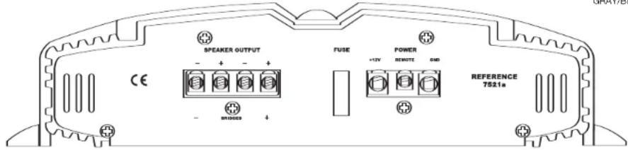
The Reference amplifiers are capable of delivering high power levels, and require a reliable connection to the vehicle's electrical system in order to perform optimally. See Figure 1 for connection location. Please adhere to the following instructions carefully.
GROUND CONNECTION
Connect the amplifier's Ground (GND) terminal to a solid point on the vehicle's metal chassis, as close to the amplifier as possible. Refer to the chart below to determine minimum wire-gauge size. Sand away any paint from this location; use a star-type-lock washer to secure the connection.
POWER CONNECTION
Connect a wire (see chart at right for appropriate gauge) directly to the vehicle's positive battery terminal, and install an appropriate fuse holder within 18" of the battery terminal. Do not install the fuse at this time. Route the wire to the amplifier's location, and connect it to the amplifier's positive (+12V) terminal. Bo sure to use appropriate grommets whenever routing wires through the firewall or other sheet metal. Failure to adequately protect the positive wire from potential damage may result in a vehicle fire. When you are done routing and connecting this wire to the battery and to the amplifier, you may install the fuse at the battery. The fuse value should be selected based on total amplifier-current draw; see chart at right.
REMOTE CONNECTION
Connect the amplifier's Remote (REMOTE) terminal to the source unit's Remote Turn-On lead using a minimum of 18-gauge wire. If you source unit does not have a remote turn-on connection, connect the amplifier's (REMOTE) terminal to the vehicle's accessory circuit.
WIRE-GAUGE CHART
Amplifier Maximum Minimum
Model Current Draw Wire Gauge
| 7521a | 34A | #8 | AWG |
| 7541a | 85A | #8 | AWG |
| 5761a | 87A | #8 | AWG |
| 311a | 40A | #8 | AWG |
| 611a | 69A | #6 | AWG |
1211a 115A #4 AWG
These recommendations assume 7' - 10' wire runs. If your installation differs markedly, you will need to adjust the wire gauge accordingly.
SPEAKER CONNECTIONS
Refer to the application guides on the pages that follow. Speaker connections should be made using a minimum of 16-gauge wire.
HIGH-LEVEL INPUT CONNECTIONS
The 7521a, 7541a and 5761a amplifiers are equipped with speaker-level inputs that allow you to add an amplifier to head units that do not have RCA line outputs. The speaker outputs for the source unit should be connected to the amplifier using the supplied connector (square four-wire plug). Remember to check for proper polarity. The 311a, 611a and 1211a amplifiers are not equipped with high-level inputs.
NOTE: When using the low-level or high-level inputs, the AUX outputs can be used to pass a full-range line-level signal to another amplifier.
Figure 2. Speaker-level connector.
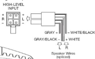
Figure 1. Terminal-connection end plate.
APPLICATIONS - 311a, 611a AND 1211a
The Reference subwoofer amplifiers are single-channel amplifiers. There are two sets of terminals to make it easy to connect multiple woofers. Either set of (+/-) terminals may be used when connecting woofers.
To the right are two application diagrams to help plan your subwoofer system installation. Figures 3 and 4 show how to configure the Reference subwoofer amplifiers (models 311a, 611a and 1211a).
NOTE: For simplicity, Figures 3 and 4 do not show power, remote and input connections.
NOTE: Minimum speaker load is 2 ohms.
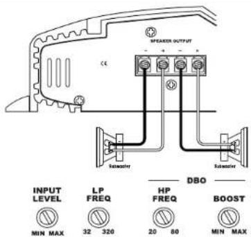
Figure 3. Reference subwoofer amplifier with two woofer connections.
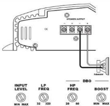
Figure 4. Reference subwoofer amplifier with one woofer connection.
APPLICATIONS - 7521a
The 7521a amplifier can be set up for stereo or bridged-mono operation, as shown in Figures 5 and 6.
NOTE: For simplicity, Figures 5 and 6 do not show power, remote and input connections.
NOTE: Minimum speaker impedance for stereo operation is 2 ohms. Minimum speaker impedance for bridged operation is 4 ohms.
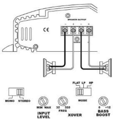
Figure 5. 7521a amplifier set up for stereo operation.
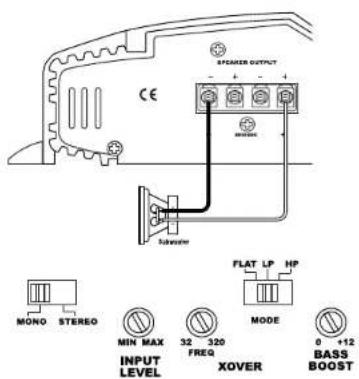
Figure 6. 7521a amplifier set up for bridged-mono operation.
APPLICATIONS - 7541a
The 7541a can be set up for stereo 4-channel, 3-channel or bridged 2-channel operation, as shown in Figures 7 through 9.
NOTE: For simplicity, Figures 7 through 9 do not show power, remote and input connections.
NOTE: Minimum speaker impedance for stereo operation is 2 ohms. Minimum speaker impedance for bridged operation is 4 ohms.
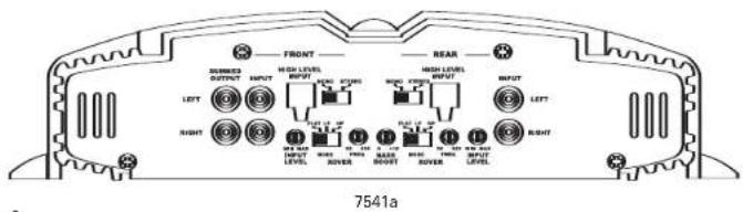
NOTE: "Bass Boost" only affects rear channels.
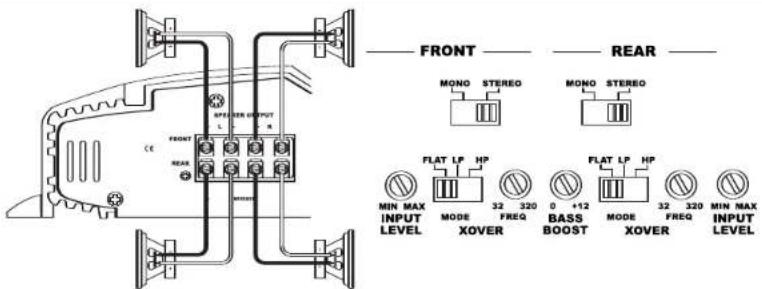
Figure 7. 7541a amplifier in 4-channel (stereo) operation to drive front and rear full-range speakers.
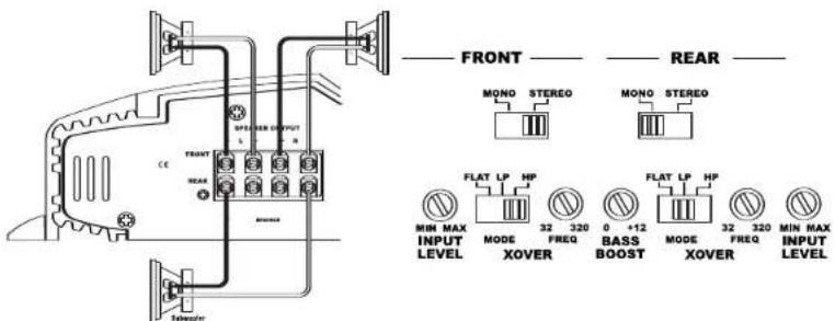
Figure 8. 7541a is set up for 3-channel operation to drive a set of full-range speakers and a subwoofer.
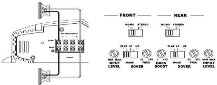
Figure 9. 7541a used in bridged 2-channel mode to drive a set of components or subwoofers.
APPLICATIONS - 5761a
The 5761a can be configured for 6-channel, 5-channel or 3-channel operation, as shown in Figures 10 through 12.
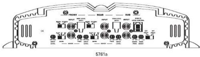
INPUT MODE SWITCH:
- Use INT (internal mode) to send a signal from the front and rear inputs to the subwoofer.
- Use EXT (external mode) when sending a dedicated signal to the subwoofer inputs; e.g., if your source unit has a subwoofer output.
NOTE: For simplicity, Figures 10 through 12 do not show power, remote and input connections.
NOTE: Minimum speaker impedance for stereo operation is 2 ohms. Minimum speaker impedance for bridged operation is 4 ohms.
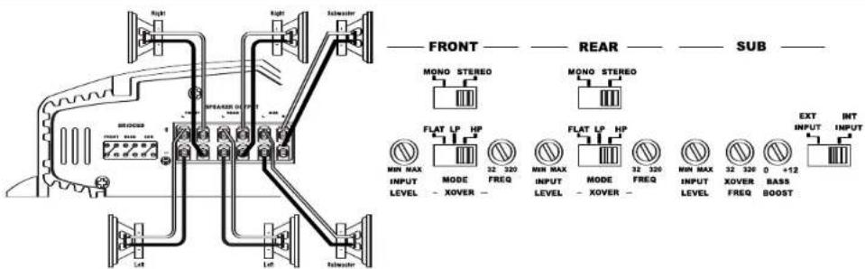
Figure 10. 6-Channel operation: 5761a amplifier driving full-range front and rear speakers and a pair of subwoofers.
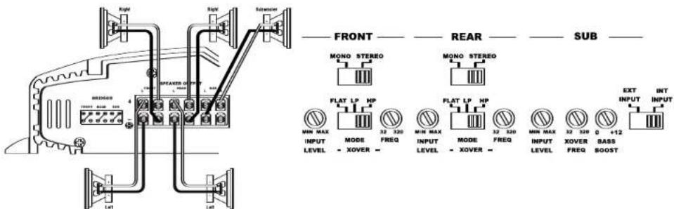
Figure 11. 5-Channel operation: The same as Figure 10, with the subwoofer output bridged to drive a single 4-ohm subwoofer, providing the speaker with more power.
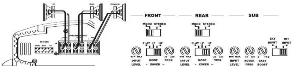
Figure 12. 3-Channel operation: 5761a amplifier configured for 3-channel operation, where all of the channels are bridged for a subwoofer and a pair of component speakers.
INSTALLATION AND SETUP
SETTING THE CROSSOVER(S)
Determine your system plans and set the crossover-mode switch accordingly. If your system design does not include a subwoofer, set the crossover mode to FLAT and skip to "Setting Input Sensitivity."
MODE SWITCH
Flat: Allows a full-range signal through to the speakers; can be used with larger full-range speakers such as 6" x 9"s.
HP: Allows a high-pass signal through to the speakers; should be used with most loudspeakers (can protect your full-range speakers from being overdriven with low frequencies, one cause of speaker damage).
LP: Allows bass to pass through to the speakers; should be selected when powering subwoofers.
Initially set the crossover-frequency control midway. While listening to music, adjust the crossover for the least perceived distortion from the speakers, allowing them to reproduce as much bass as possible.
Systems using a separate subwoofer set the crossover mode to HP (high-pass) for your full-range speakers. Adjust the crossover frequency to limit bass, and provide increased system volume with less distortion.
For subwoofers, choose the highest frequency that removes vocal information from the sound of the subwoofer.
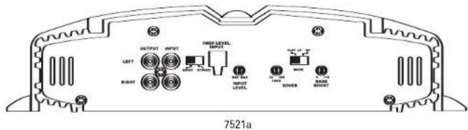
If using the 7521a or 7541a to drive a subwoofer(s), set the crossover mode to LP (low-pass).
NOTE: The 311a, 611a, 1211a and the subwoofer output of the 5761a are low-pass only and do not have a crossover-mode switch.
SETTING INPUT SENSITIVITY
- Initially turn the INPUT LEVEL control(s) to minimum (counterclockwise).
- Reconnect the (−) negative lead to the vehicle's battery. Apply power to the audio system and play a dynamic music track.
- On the source unit, increase the volume control to 3/4 volume. Slowly increase the INPUT LEVEL control(s) toward three o'clock until you hear slight distortion in the music. Then reduce the INPUT LEVEL slightly until distortion is no longer heard.
NOTE: After the source unit is on, blue LEDs (on the top panel) will light, indicating the amplifier is on. If not, check the wiring, especially the remote connection from the source unit. Also refer to "Troubleshooting" on page 7.
REMOTE LEVEL CONTROL (OPTIONAL)
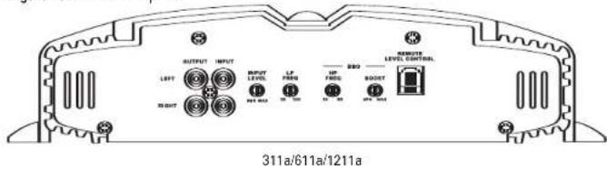
All three Reference subwoofer amplifiers and the 5761a amplifier have inputs for an optional remote level control (100rc). This will allow the subwoofer level to be adjusted from the listening position. Connect the optional remote level control using the RJ-11 jack on the side of the amplifier. Install the control module in the front of the vehicle within easy reach of the driver. Both the underside of the dash and the center console are suitable locations. Refer to the mounting instructions accompanying the 100rc.
SETTING THE BASS BOOST
The 7521a, 7541a and 5761a are all equipped with a bass-boost control. This allows you to enhance the bass output of your system at 50Hz up to 12dB.
NOTE: Only rear channels of the 7541a are affected by the bass boost control.
AUX OUTPUT
Reference amplifiers (except 5761a) are equipped with full-range outputs that can be used to connect additional amplifiers.
NOTE: When using the low- or high-level inputs, the AUX outputs can be used to pass a full-range line-level signal to another amplifier.
Figure 13. Control end panel.
INSTALLATION AND SETUP (CONT.)
SETTING DBO (311a, 611a and 1211a)
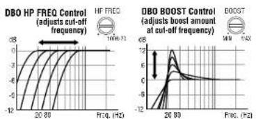
The Dynamic Bass Optimizer (DBO) is used to enhance low-frequency reproduction in a vehicle. Conventional bass-boost circuits only increase bass at a fixed frequency, and cause the amplifier to consume considerable power. The DBO allows you to adjust the frequency (20Hz - 80Hz) as well as the boost level (up to 12dB; see Figure 14), allowing you to fine-tune the bass in your system to optimize performance.
For sealed enclosures, the DBO can be used to enhance the lower bass region of sealed enclosures.
For bigger/fuller bass, adjust the HP FREQ between 35Hz and 45Hz; adjust the BOOST control according to your preference.
For tighter-sounding bass, adjust the HP FREQ between 45Hz and 55Hz; adjust the BOOST control according to your preference.
For vented enclosures, the DBO should be used as a subsonic filter to reduce overexcursion of the woofers. Set the HP FREQ control 10Hz below the tuning frequency of the enclosure (e.g., 25Hz for a box tuning of 35Hz); adjust the BOOST control to taste. This will conserve amplifier power typically wasted on frequencies below the tuned frequency of the enclosure.
For infinite-baffle applications, set the HP FREQ to the speaker's Fs value (reducing overexcursion of the woofer); adjust the Boost control to taste.
Figure 14. Frequency-response curves show typical DBO control ranges.
STATUS LEDs
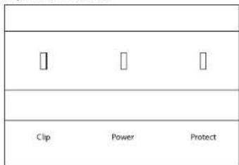
Clip: Indicates the amplifier is being overdriven, and your speakers may be in danger. This should blink only on musical peaks, and not be on constantly.
Power: Indicates the amplifier is on. Protection: Refer to "Troubleshooting" for specific indications.
Figure 15. LED status.
TROUBLESHOOTING
• PROBLEM:
No audio (POWER LED is off).
CAUSE and SOLUTION:
No voltage at BATT+ and/or REM terminals, or bad or no ground connection. Check voltages at amplifier terminals with VOM.
• PROBLEM:
No audio (PROTECT LED flashes every 4 seconds).
CAUSE and SOLUTION:
DC voltage on amplifier output. Amplifier may need service; see enclosed warranty card for service information.
• PROBLEM:
No audio (PROTECT LED is on).
CAUSE and SOLUTION:
Amplifier is overheated. Make sure amplifier cooling is not blocked at mounting location; verify that speaker-system impedance is within specified limits.
• PROBLEM:
No audio (PROTECT and POWER LEDs flash).
CAUSE and SOLUTION:
Voltage less than 9V on BATT+ connection. Check vehicle charging system.
• PROBLEM:
No audio (PROTECT LED is on).
CAUSE and SOLUTION:
Voltage greater than 16V or less than 8.5V on BATT+ connection. Check vehicle charging system.
• PROBLEM:
Distorted audio.
CAUSE and SOLUTION:
Input sensitivity is not set properly, or amplifier or source unit is defective. Check INPUT LEVEL setting, or check speaker wires for shorts or grounds.
• PROBLEM:
Distorted audio (PROTECT LED flashes).
CAUSE and SOLUTION:
Short circuit in speaker or wire. Remove speaker leads one at a time to locate shorted speaker or wire, then repair.
• PROBLEM:
Music lacks "punch."
CAUSE and SOLUTION:
Speakers are not connected properly. Check speaker connections for proper polarity.
SPECIFICATIONS
311a
• 116W RMS x 1 channel at 4 ohms and ≤1% THD + N
• Signal-to-noise ratio: 81dBA (reference 1W into 4 ohms)
- 312W RMS x 1 channel at 2 ohms, 14.4V supply and ≤1% THD + N
• Dynamic power: 347W at 2 ohms
• Effective damping factor: 6.398 at 4 ohms
• Frequency response: 17Hz - 302Hz (-3dB)
• Maximum input signal: 6V
• Maximum sensitivity: 75mV
- Output regulation: .05dB at 4 ohms
- Dimensions (L x W x H): 12" x 11-7/16" x 2-11/16"
- Fuse rating: 1 x 30A
7521a
- 97W RMS x 2 channels at 4 ohms and ≤1% THD + N
• Signal-to-noise ratio: 83dBA (reference 1W into 4 ohms) - 142W RMS x 2 channels at 2 ohms, 14.4V supply and ≤1% THD + N
- 283W RMS x 1 channel at 4 ohms, 14.4V supply and ≤1% THD + N
• Dynamic power: 190W at 2 ohms
• Effective damping factor: 6.389 at 4 ohms
• Frequency response: 10Hz - 69kHz (-3dB)
• Maximum input signal: 5.5V
• Maximum sensitivity: 75mV
• Output regulation: .078dB at 4 ohms - Dimensions (L x W x H): 12" x 11-7/16" x 2-11/16"
- Fuse rating: 1 x 30A
611a
- 456W RMS x 1 channel at 4 ohms and ≤1% THD + N
• Signal-to-noise ratio: 70dBA (reference 1W into 4 ohms) - 657W RMS x 1 channel at 2 ohms, 14.4V supply and ≤1% THD + N
• Dynamic power: 761W at 2 ohms
• Effective damping factor: 6.336 at 4 ohms
• Frequency response: 17Hz - 302Hz (-3dB)
• Maximum input signal: 6V
• Maximum sensitivity: 75mV
• Output regulation: .179dB at 4 ohms
• Dimensions (L x W x H): 12" x 15" x 2-11/16" - Fuse rating: 2 x 30A
7541a
• 111W RMS x 4 channels at 4 ohms and ≤1% THD + N
• Signal-to-noise ratio: 81dBA (reference 1W into 4 ohms)
- 139W RMS x 4 channels at 2 ohms, 14.4V supply and ≤1% THD + N
- 278W RMS x 2 channels at 4 ohms, 14.4V supply and ≤1% THD + N
• Dynamic power: 164W at 2 ohms
• Effective damping factor: 6.315 at 4 ohms
• Frequency response: 10Hz - 100kHz (-3dB)
• Maximum input signal: 5.5V
• Maximum sensitivity: 75mV
• Output regulation: .088dB at 4 ohms
- Dimensions (L x W x H): 12" x 15" x 2-11/16"
- Fuse rating: 2 × 30A
1211a
- 854W RMS x 1 channel at 4 ohms and ≤1% THD + N
• Signal-to-noise ratio: 72dBA (reference 1W into 4 ohms) - 1300W RMS x 1 channel at 2 ohms, 14.4V supply and ≤1% THD + N
• Dynamic power: 1516W at 2 ohms
• Effective damping factor: 6.357 at 4 ohms
• Frequency response: 17Hz - 302Hz (-3dB)
• Maximum input signal: 5.7V
• Maximum sensitivity: 75mV
• Output regulation: .132dB at 4 ohms
• Dimensions (L x W x H): 12' x 18-1/2" x 2-11/16" - Fuse rating: 3 x 40A
5761a
- 56W x 4 channels and 107W x 2 channels, at 4 ohms and ≤1% THD + N
• Signal-to-noise ratio: 82dBA (reference 1W into 4 ohms) - 80W x 4 channels, 150W x 2 channels at 2 ohms, 14.4V supply and ≤1% THD + N
- 148W x 2 channels, 287W x 1 channel at 4 ohms, 14.4V supply and ≤1% THD + N
• Dynamic power: 117W (channels 1, 2, 3, 4);
163W (channels 5, 6) into 2 ohms
• Effective damping factor: 6.373 at 4 ohms - Frequency response: 10Hz – 57kHz (channels 1, 2, 3, 4); 10Hz – 302Hz (channels 5, 6)
• Maximum input signal: 6.3V
• Maximum sensitivity: 75mV
• Output regulation: .063dB at 4 ohms
• Dimensions (L x W x H): 12" x 18-1/2" x 2-11/16" - Fuse rating: 2 x 30A

A valid serial number is required for warranty coverage.
Features, specifications and appearance are subject to change without notice.
These products are designed for mobile applications and are not intended for connection to the mains.

TECHNOLOGY - PERFORMANCE - DESIGN
Infinity Systems, 250 Crossways Park Drive, Woodbury, NY 11797 USA
www.infinitysystems.com
© 2008 Harman International Industries, Incorporated. All rights reserved. Part No. REFAMPOM10/06
Infinity is a trademark of Harman International Industries, Incorporated, registered in the United States and/or other countries.
H A Harman International Company

- Infinity®
- INTRODUCTION
- WARNING!
- IMPORTANT
- INSTALLATION WARNINGS AND TIPS
- CHOOSING A LOCATION AND MOUNTING THE AMPLIFIER
- POWER CONNECTIONS
- GROUND CONNECTION
- POWER CONNECTION
- REMOTE CONNECTION
- WIRE-GAUGE CHART
- SPEAKER CONNECTIONS
- HIGH-LEVEL INPUT CONNECTIONS
- APPLICATIONS - 311a, 611a AND 1211a
- APPLICATIONS - 7521a
- APPLICATIONS - 7541a
- APPLICATIONS - 5761a
- INPUT MODE SWITCH:
- INSTALLATION AND SETUP
- SETTING THE CROSSOVER(S)
- MODE SWITCH
- SETTING INPUT SENSITIVITY
- REMOTE LEVEL CONTROL (OPTIONAL)
- SETTING THE BASS BOOST
- AUX OUTPUT
- INSTALLATION AND SETUP (CONT.)
- SETTING DBO (311a, 611a and 1211a)
- STATUS LEDs
- TROUBLESHOOTING
- • PROBLEM:
- SPECIFICATIONS
- 311a
- 7521a
- 611a
- 7541a
- 1211a
- 5761a
Brand : INFINITY
Model : Reference 311a
Category : Receiver