
M2E4BTB3 - Computer storage case StarTech.com - Free user manual and instructions
Find the device manual for free M2E4BTB3 StarTech.com in PDF.


| Product Type | 4-Bay M.2 NVMe Enclosure |
| Model | M2E4BTB3 |
| Brand | StarTech.com |
| Interface | Thunderbolt 3 (USB-C) |
| Supported Drive Type | M.2 NVMe (M-key, 2280 form factor) |
| Number of Drive Bays | 4 |
| Power Input | DC 12V via included Universal Power Adapter |
| Thunderbolt 3 Ports | 2 (up to 40 Gbps each) |
| DisplayPort Output | 1 (supports up to 4096x2160p @ 60Hz) |
| Max Supported Resolution (via Thunderbolt 3) | 5120x2880p @ 60Hz (single display) |
| Daisy Chain Support | Yes, for multiple Thunderbolt 3 devices |
| Cooling | Built-in fan on bottom of enclosure |
| Thermal Management | Thermal pads between drives and enclosure body |
| LED Indicators | Power LED and drive activity LEDs (1-4) |
| Operating Temperature | Warm due to Thunderbolt performance; no safety hazard |
| Warranty | 2 years |
| Compliance | FCC Class B, ICES-003 |
Frequently Asked Questions - M2E4BTB3 StarTech.com
User questions about M2E4BTB3 StarTech.com
0 question about this device. Answer the ones you know or ask your own.
Ask a new question about this device
Download the instructions for your Computer storage case in PDF format for free! Find your manual M2E4BTB3 - StarTech.com and take your electronic device back in hand. On this page are published all the documents necessary for the use of your device. M2E4BTB3 by StarTech.com.
USER MANUAL M2E4BTB3 StarTech.com
4-Bay M.2 NVMe Enclosure - Thunderbolt™ 3 - PCIe

natural_image
Black StarTech.com power bank device with visible ports and indicator lights (no text or symbols on body)Actual product may vary from photos
User Manual
SKU#: M2E4BTB3
For the latest information and specifications visit
www.startech.com/M2E4BTB3
Compliance Statements
FCC Compliance Statement
This equipment has been tested and found to comply with the limits for a Class B digital device, pursuant to part 15 of the FCC Rules. These limits are designed to provide reasonable protection against harmful interference in a residential installation. This equipment generates, uses and can radiate radio frequency energy and, if not installed and used in accordance with the instructions, may cause harmful interference to radio communications. However, there is no guarantee that interference will not occur in a particular installation. If this equipment does cause harmful interference to radio or television reception, which can be determined by turning the equipment off and on, the user is encouraged to try to correct the interference by one or more of the following measures:
• Reorient or relocate the receiving antenna
- Increase the separation between the equipment and receiver
- Connect the equipment into an outlet on a circuit different from that to which the receiver is connected
- Consult the dealer or an experienced radio/TV technician for help
Industry Canada Statement
This Class B digital apparatus complies with Canadian ICES-003.
Use of Trademarks, Registered Trademarks, and other Protected Names and Symbols
This manual may make reference to trademarks, registered trademarks, and other protected names and/or symbols of third-party companies not related in any way to StarTech.com. Where they occur these references are for illustrative purposes only and do not represent an endorsement of a product or service by StarTech.com, or an endorsement of the product(s) to which this manual applies by the third-party company in question. Regardless of any direct acknowledgement elsewhere in the body of this document, StarTech.com hereby acknowledges that all trademarks, registered trademarks, service marks, and other protected names and/or symbols contained in this manual and related documents are the property of their respective holders.
PHILLIPS® is a registered trademark of Phillips Screw Company in the United States or other countries.
Safety Statements
Safety Measures
- Wiring terminations should not be made with the product and/or electric lines under power.
- Cables (including power and charging cables) should be placed and routed to avoid creating electric, tripping or safety hazards.
Mesures de sécurité
To view manuals, videos, drivers, downloads, technical drawings, and more visit www.startech.com/support
Table of Contents
Compliance Statements......i
Safety Statements......ii
Product Diagram....1
Side View 1
Top Angled View....2
Bottom View - Drive Bay Closed....3
Bottom View - Drive Bay Open 4
Requirements ....5
Installation 5
Connect the Drives....5
(Optional) Connect a Thunderbolt 3 Peripheral....6
(Optional) Connect Displays 6
Powering the Enclosure....7
Connect the Enclosure to the Host Computer 7
Operation 8
Operating Temperature 8
Removing the Drives....8
Supported Video Resolutions....9
Daisy Chain Multiple Thunderbolt 3 Devices....10
Configure the Display Devices 10
Warranty Information......11
Product Diagram
Side View

| Component Function | ||
| 1 | Thunderbolt 3 Ports | Connect the Enclosure to the Host ComputerConnect Thunderbolt 3 PeripheralsCascade the Enclosure to other EnclosuresConnect a Thunderbolt 3 Enabled Display Device |
| 2 | DisplayPort Output Port | Connect a DisplayPort Enabled Display Device |
| 3 | DC 12V Power Port | Connect a Universal Power Adapter |
| 4 | Rubber Foot Pads | Prevent scratchingAllow air to flow under the Enclosure |
To view manuals, videos, drivers, downloads, technical drawings, and more visit www.startech.com/support
Top Angled View
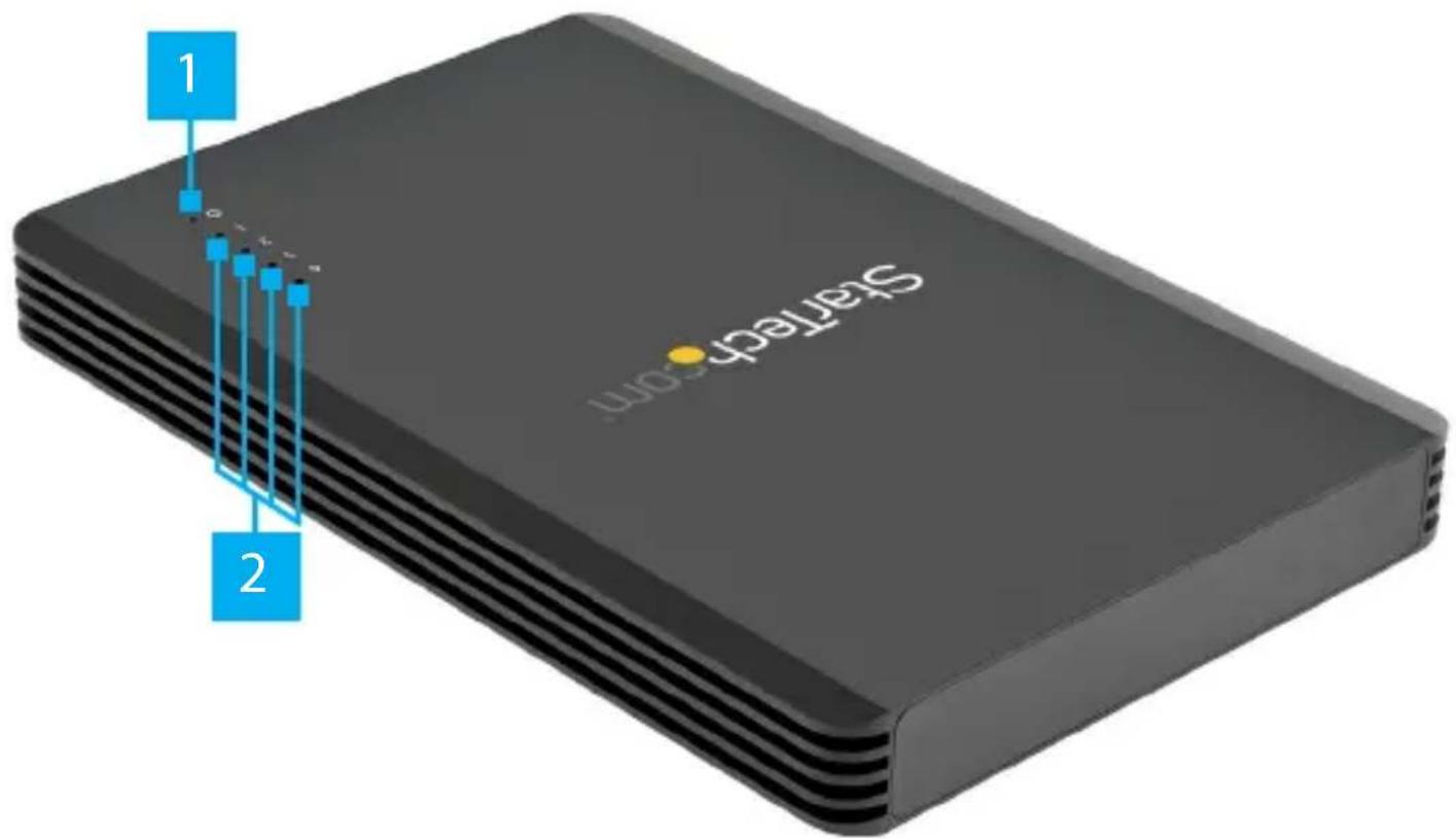
| Component Status Indication | |||
| 1 | Power LED Indicator | On · Enclosure is receiving power from the Universal Power Adapter | |
| Off | · Universal Power Adapter is not connected | ||
| 2 | Drive Activity LED Indicators | · Correspond with M.2 Drives 1-4 | |
| On/ Flashing | · M.2 Drive activity detected | ||
| Off · M.2 | Drive not connected· No M.2 Drive activity detected | ||
To view manuals, videos, drivers, downloads, technical drawings, and more visit www.startech.com/support
Bottom View - Drive Bay Closed

| Component Function | ||
| 1 | Drive Bay Screws | ·Secure the Drive Bay Cover |
| 2 | Drive Bay Cover | ·Cover and protect the M.2 Drives |
| 3 | Fan | ·Cool the M.2 Drives |
To view manuals, videos, drivers, downloads, technical drawings, and more visit www.startech.com/support
Bottom View - Drive Bay Open

| Component Function | ||
| 1 | Thermal Pads | Transfer heat from the M.2 Drives to the body of the Enclosure |
| 2 | M-Key Socket | Connect up to 4 M.2 DrivesDrives are numbered to correspond with the Drive Activity LED Indicators (from left to right: 1, 2, 3, 4) |
To view manuals, videos, drivers, downloads, technical drawings, and more visit www.startech.com/support
Requirements
For the latest requirements please visit www.startech.com/M2E4BTB3.
- Host Computer with a Thunderbolt 3 Port
- M-Key Connector Type, 22 x 80 mm (2280), M.2 Drive x (Up to) 4
• (Optional) Thunderbolt 3 Enabled Display Device x 1
• (Optional) Thunderbolt 3 Cable x 1 - (Optional) DisplayPort Enabled Display Device x 1
• (Optional) DisplayPort Cable x 1
• (Optional) Thunderbolt 3 Peripheral x 1 - (Optional) Thunderbolt 3 to DisplayPort Adapter Cable x 1
Installation
Connect the Drives
- Turn the Enclosure upside down.
- Remove the Drive Bay Cover on the bottom of the Enclosure:
- Remove the two Drive Bay Screws using a Phillips Head Screwdriver.
- Carefully flip the Enclosure to release the Drive Bay Cover.
-
Remove the Holding Screw for the M.2 Drive using a Phillips Head Screwdriver.
-
Slide the M.2 Drive into the M-Key Socket at a 45 degree angle.
To view manuals, videos, drivers, downloads, technical drawings, and more visit www.startech.com/support
Note: Ensure the M.2 Drive is properly seated, with the pins making full contact, before proceeding to the next step.
- Gently press down on the M.2 Drive until the notch on the M.2 Drive is aligned with the hole for the Holding Screw.
- While holding the M.2 Drive in place, secure the M.2 Drive by replacing the Holding Screw that was removed in step 3, using a Phillips Head Screwdriver.
- Repeat steps 3-6 to install the remaining M.2 Drives.
- Replace the Drive Bay Cover that was removed in step 2.
- Screw in the two Drive Bay Screws that were removed in step one, using a Phillips Head Screwdriver.
(Optional) Connect a Thunderbolt 3 Peripheral
- Connect a Thunderbolt 3 Cable (sold separately) to one of the Thunderbolt 3 Ports on the Enclosure and to a Thunderbolt 3 Port on the Thunderbolt 3 Peripheral.
--Or--
- Connect a Thunderbolt 3 Peripheral directly to one of the Thunderbolt 3 Ports on the Enclosure.
(Optional) Connect Displays
Note: Connect and setup the DisplayPort Enabled Display Device before connecting and setting up the Thunderbolt 3 Enabled Display Device.
To view manuals, videos, drivers, downloads, technical drawings, and more visit www.startech.com/support
DisplayPort Enabled Display Device
- Connect a DisplayPort Cable (sold separately) to the DisplayPort Output Port on the Enclosure and to a DisplayPort Input Port on a DisplayPort Enabled Display Device.
DisplayPort Enabled Display Device via Thunderbolt 3 Port
- Connect a Thunderbolt 3 to DisplayPort Adapter Cable to one of the Thunderbolt 3 Ports on the Enclosure and to a DisplayPort Input Port on a DisplayPort Enabled Display Device.
Thunderbolt 3 Enabled Display Device
- Connect a Thunderbolt 3 Cable (included) to one of the Thunderbolt 3 Ports on the Enclosure and to a Thunderbolt 3 Input Port on a Thunderbolt 3 Enabled Display Device.
Powering the Enclosure
-
Select the appropriate regional Power Cord and connect it to the Universal Power Adapter.
-
Connect the Universal Power Adapter to the DC 12V Power Port on the Enclosure and to an AC Electrical Outlet.
Connect the Enclosure to the Host Computer
The Thunderbolt 3 Ports allow for a connection from the Host Computer to the Enclosure.
- Connect a Thunderbolt 3 Cable (included) to one of the Thunderbolt 3 Ports on the Enclosure and to a Thunderbolt 3 Port on the Host Computer.
To view manuals, videos, drivers, downloads, technical drawings, and more visit www.startech.com/support
Operation
Operating Temperature
Due to the high performance of Thunderbolt technology, Thunderbolt products sometimes generate more heat than traditional hardware. Therefore, it's normal for the Enclosure to warm up when in use. As such, it's recommended that the Enclosure is not placed on any part of the Host Computer's surface, as doing so will result in even higher temperatures.
These higher temperatures do not present a safety hazard to the user.
Removing the Drives
Notes: After extended use the M.2 Drives may stick to the Thermal Pads. The labels of the M.2 Drives may become damaged during removal. This will not impact the performance of the M.2 Drives.
The Thermal Pads may leave residue on the M.2 Drives during removal.
- Turn the Enclosure upside down.
-
Remove the Drive Bay Cover on the bottom of the Enclosure:
-
Remove the two Drive Bay Screws using a Phillips Head Screwdriver.
-
Carefully flip the Enclosure to release the Drive Bay Cover.
-
Remove the Holding Screw for the M.2 Drive using a Phillips Head Screwdriver.
To view manuals, videos, drivers, downloads, technical drawings, and more visit www.startech.com/support
- Slide the M.2 Drive out of the M-Key Socket at a 45 degree angle.
Supported Video Resolutions
The Enclosure supports the following maximum resolutions:
| Number of Displays | Ports Maximum Resolution | |
| 1 | DisplayPort Output Port | 4096 x 2160p (60Hz) |
| 1 Thunderbolt 3 | Port 5120 x 2880 p (60Hz) | |
| 2 | DisplayPort Output Port and Thunderbolt 3 Peripheral Port | 4096 x 2160p (60Hz) |
| 2 | DisplayPort Output Port and Thunderbolt 3 Peripheral Port (USB-C to DisplayPort) | 4096 x 2160p (60Hz) |
- Depending on the configuration and the supported resolutions of the connected Display Device(s), the Enclosure can support video resolutions lower than specified above.
- In a multi-display configuration, set the refresh rates on each of the connected Display Devices to the same values, otherwise the Display Devices might not properly display.
To view manuals, videos, drivers, downloads, technical drawings, and more visit www.startech.com/support
• Video output capabilities are dependent on the video card and hardware specifications of the connected Host Computer.
Daisy Chain Multiple Thunderbolt 3 Devices
Dual displays using multiple Thunderbolt 3 Display Devices can be used in a daisy chain configuration. For example, connect a Thunderbolt 3 Display Device to a Thunderbolt 3 Port on the Enclosure. Then connect another Thunderbolt 3 Display Device or a Thunderbolt 3 Peripheral Device through the first Thunderbolt 3 Display Device.
Configure the Display Devices
Use the Windows operating system to adjust display settings for multiple Display Devices. The Host Computer's hardware must support dual external displays through its Thunderbolt 3 Port.
Warranty Information
This product is backed by a two-year warranty.
For further information on product warranty terms and conditions, please refer to www.startech.com/warranty.
Limitation of Liability
In no event shall the liability of StarTech.com Ltd. and StarTech.com USA LLP (or their officers, directors, employees or agents) for any damages (whether direct or indirect, special, punitive, incidental, consequential, or otherwise), loss of profits, loss of business, or any pecuniary loss, arising out of or related to the use of the product exceed the actual price paid for the product.
Some states do not allow the exclusion or limitation of incidental or consequential damages. If such laws apply, the limitations or exclusions contained in this statement may not apply to you.
Hard-to-find made easy. At StarTech.com, that isn't a slogan. It's a promise.
StarTech.com is your one-stop source for every connectivity part you need. From the latest technology to legacy products — and all the parts that bridge the old and new — we can help you find the parts that connect your solutions.
We make it easy to locate the parts, and we quickly deliver them wherever they need to go. Just talk to one of our tech advisors or visit our website. You'll be connected to the products you need in no time.
Visit www.startech.com for complete information on all StarTech.com products and to access exclusive resources and time-saving tools.
StarTech.com is an ISO 9001 Registered manufacturer of connectivity and technology parts. StarTech.com was founded in 1985 and has operations in the United States, Canada, the United Kingdom and Taiwan servicing a worldwide market.
Reviews
Share your experiences using StarTech.com products, including product applications and setup, what you love about the products, and areas for improvement.
StarTech.com Ltd.
45 Artisans Cres.
London, Ontario
N5V 5E9
Canada
StarTech.com LLP
2500 Creekside Pkwy.
Lockbourne, Ohio
43137
U.S.A.
StarTech.com Ltd.
Unit B, Pinnacle
15 Gowerton Rd., Brackmills
Northampton
NN4 7BW
United Kingdom
FR: startech.com/fr
DE: startech.com/de
ES: startech.com/es
NL: startech.com/nl
IT: startech.com/it
JP: startech.com/jp
- 4-Bay M.2 NVMe Enclosure - Thunderbolt™ 3 - PCIe
- Compliance Statements
- FCC Compliance Statement
- Industry Canada Statement
- Use of Trademarks, Registered Trademarks, and other Protected Names and Symbols
- Safety Statements
- Safety Measures
- Mesures de sécurité
- Table of Contents
- Product Diagram
- Bottom View - Drive Bay Open
- Requirements
- Installation
- Connect the Drives
- (Optional) Connect a Thunderbolt 3 Peripheral
- (Optional) Connect Displays
- DisplayPort Enabled Display Device
- DisplayPort Enabled Display Device via Thunderbolt 3 Port
- Thunderbolt 3 Enabled Display Device
- Powering the Enclosure
- Connect the Enclosure to the Host Computer
- Operation
- Operating Temperature
- Removing the Drives
- Supported Video Resolutions
- Daisy Chain Multiple Thunderbolt 3 Devices
- Configure the Display Devices
- Warranty Information
- Limitation of Liability
- Hard-to-find made easy. At StarTech.com, that isn't a slogan. It's a promise.
- Reviews
Brand : StarTech.com
Model : M2E4BTB3
Category : Computer storage case