Epic Five - Receiver AudioControl - Free user manual and instructions
Find the device manual for free Epic Five AudioControl in PDF.


| Product Type | Five-Channel Class D Car Amplifier |
| Brand | AudioControl |
| Model | Epic Five |
| Power Output (RMS @ 4 ohms) | 4 x 75 Watts + 1 x 300 Watts |
| Power Output (RMS @ 2 ohms) | 4 x 150 Watts + 1 x 500 Watts |
| Power Output (Subwoofer @ 1 ohm) | 1 x 700 Watts |
| Power Output (Bridged @ 4 ohms) | 2 x 400 Watts |
| Amplifier Topology | Class D |
| Frequency Response | 10 Hz - 24 kHz (Ch1-4), 12 Hz - 181 Hz (Ch5) |
| Signal-to-Noise Ratio | 92.1 dBa (ref 75W @ 4 ohms) |
| High Pass Filter | 12 dB/octave Linkwitz-Riley, variable 50-500 Hz |
| Low Pass Filter | 12 dB/octave Linkwitz-Riley, variable 40-180 Hz |
| Subsonic Filter | 12 dB/octave Linkwitz-Riley, variable off-50 Hz |
| EPICBoost | Fixed 45 Hz, 0 to +12 dB boost |
| Input Sensitivity | 500 mV - 6 V RMS |
| Input Mode | 2Ch, 4Ch, 5Ch switchable |
| Protection Circuit | Smart Auto-Reset (OCP, OVP, UVP, DCP, OTP) |
| Remote Level Control | Included ACR-E (not compatible with ACR-1) |
| Recommended Fuse Rating | 150 Amps (external) |
| Power/Ground Wire Gauge | 4 AWG |
| Speaker Wire Gauge | 8 AWG |
| Dimensions (L x W x H) | 13.35 x 6.1 x 2.01 inches (339 x 155 x 51 mm) |
| Included Accessories | ACR-E remote, wrench, screws, EPICENTER LINK harness, manual |
Frequently Asked Questions - Epic Five AudioControl
User questions about Epic Five AudioControl
0 question about this device. Answer the ones you know or ask your own.
Ask a new question about this device
Download the instructions for your Receiver in PDF format for free! Find your manual Epic Five - AudioControl and take your electronic device back in hand. On this page are published all the documents necessary for the use of your device. Epic Five by AudioControl.
USER MANUAL Epic Five AudioControl
Features
• Compact High-Power Class D Amplifier
• High-Current Design
- 4 x 75 Watts + 1 x 300 Watts @ 4 ohms
- 4 x 150 Watts + 1 x 500 Watts @ 2 ohms
• 1 x 700 Watts @ 1 ohm
• 2 x 300 Watts @ 4 ohms Bridged
• Smart Auto-Reset Protection Circuit
• 12 dB/octave Linkwitz-Riley Variable HP/LP Filters
• 12 dB/octave Variable Subsonic Filter
• Solid Power/Speaker Terminals with Hex Screws
- You're not ready for this
EPICFIVE
FIVE CHANNEL AMPLIFIER
Quick Start Guide
Important Safety Instructions
- Read these instructions.
- Keep these instructions.
- Heed all warnings.
- Follow all instructions.
- Do not use this apparatus near water.
- Clean only with a dry cloth.
- Do not block any ventilation openings. Install in accordance with the manufacturer's instructions.
- Do not install near any heat sources such as mufflers, silencers, exhaust pipes, or other apparatus (including amplifiers) that produce heat.
- WARNING: Improper installation may lead to permanent injury or death. Installation of the apparatus must be done with great care by qualified personnel, to prevent damage to fuel lines, power and other electrical wiring, hydraulic brake lines, and other systems, that might compromise vehicle safety.
- Provide +12V and Ground wiring of sufficient size to ensure adequate current to the amplifier.
- Use rubber grommets to protect wiring whenever passing wires through metal openings or bulkheads.
- Only use attachments/accessories specified by the manufacturer.
-
Refer all servicing to qualified service personnel. Servicing is required when the apparatus has been damaged in any way, such as the power input terminals are damaged or objects have fallen into the apparatus, does not operate normally, or has been dropped.
-
Fuses shall be replaced only with the correct type and fuse value, and only when the apparatus is powered off.
- Exposure to high sound pressure levels may lead to permanent hearing loss. Take every precaution to protect your hearing.

The lightning flash with arrowhead symbol within an equilateral triangle is intended to alert the user to the presence of uninsulated "dangerous voltage" within the product's enclosure, that may be of sufficient magnitude to constitute a risk of electric shock to persons.

The exclamation point within an equilateral triangle is intended to alert the user of the presence of important operating and maintenance (servicing) instructions in the literature accompanying the appliance.
Caution: to reduce the risk of electric shock, do not disassemble the apparatus, other than to remove the top panel to access the controls.
There are no user-serviceable parts inside. Refer servicing to qualified personnel.


Recycling notice: If the time comes and this apparatus has fulfilled its destiny, do not throw it out into the trash. It has to be carefully recycled for the good of mankind, by a facility specially equipped for the safe recycling of electronic apparatii. Please contact your local or state recycling leaders for assistance in locating a suitable nearby recycling facility. Or, contact us and we might be able to repair it for you.
Connections & Control Panel Features
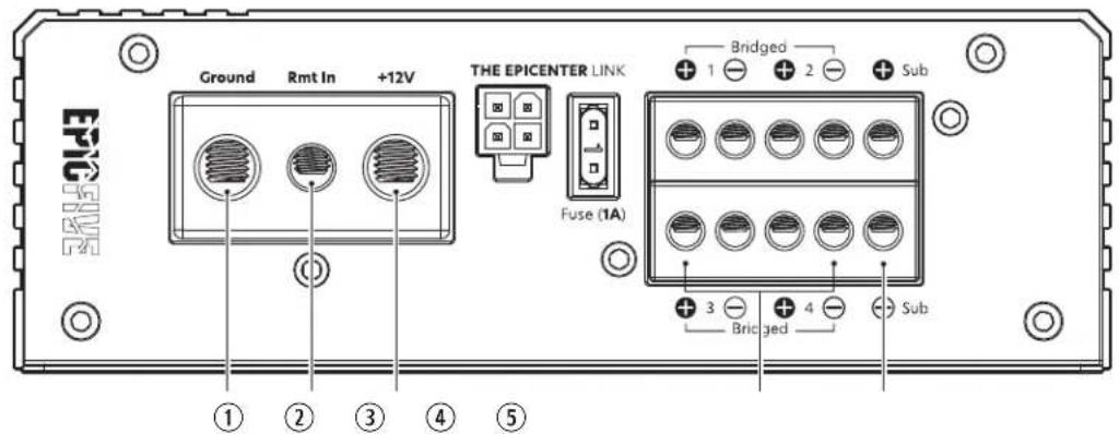
- Ground Terminal – This screw terminal connects to a clean, solid ground in the vehicle. Use the shortest length possible of quality insulated wire of the recommended wire gauge (see specifications).
- Remote Power Input Wire – This wire connects to the 12V remote trigger output of some head units and controls the on/off state of the amplifier.
-
Power Input Terminal +12V – This screw terminal connects to the +12V binding post of the vehicle battery. Use quality insulated wire of the same gauge used for the Ground connection.
-
Speaker Output – Connect these speaker terminals to your speakers using quality insulated wiring of the recommended wire gauge (see specifications). Make sure the speaker impedance does not dip below 2 ohms, or 4 ohms in bridged mono mode.
- Subwoofer Output – Connect these terminals to your subwoofer using quality insulated wiring of the recommended wire gauge (see specifications). Make sure the subwoofer impedance does not dip below 1 ohm.
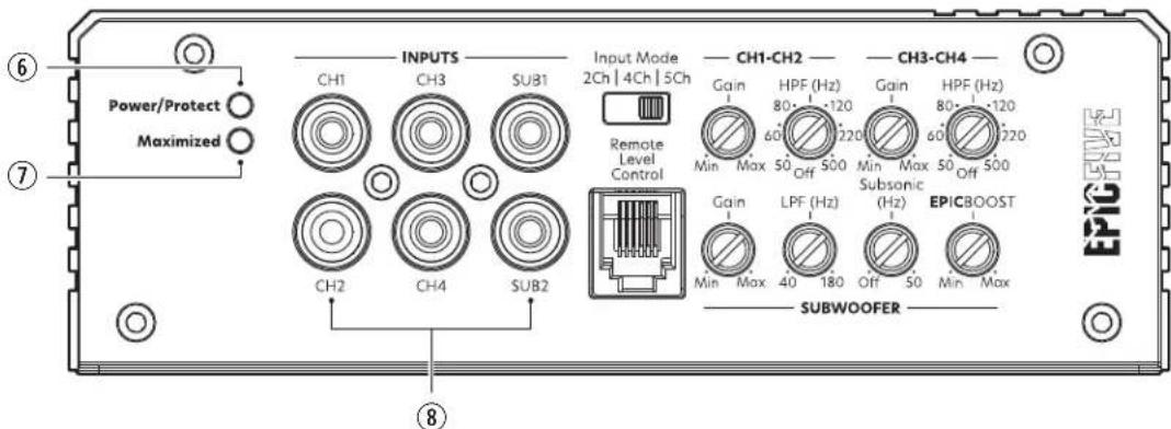
- Power/Protect LED - When the unit has been powered on, this LED will glow a soothing blue, a color rarely seen in our Northwest skies.
If this LED illuminates red, the amp is not blushing; this signifies the amp is in protection mode and something is wrong. EPIC Series amplifiers feature a Smart Auto-Reset Protection circuit (see page 6). If cycling the power to the amplifier does not take the amp out of protection, try disconnecting the speaker wires and cycle power. If the amp is no longer in protection, check the speakers and wires for shorting. If the LED stays on with the speaker wires disconnected then contact AudioControl technical support for further instruction.
-
Maximized LED – This LED indicates when the amplifier inputs have been optimized for maximum performance. This LED should illuminate momentarily during brief bursts of music play back at max volume. In most scenarios, it should not be constantly illuminated for long periods of time.
-
RCA Inputs - Connect the line level outputs from your source or line output converter (LOC) to these inputs.
-
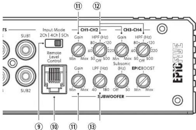
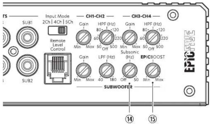
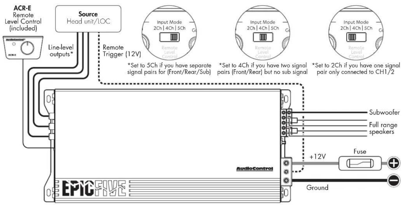
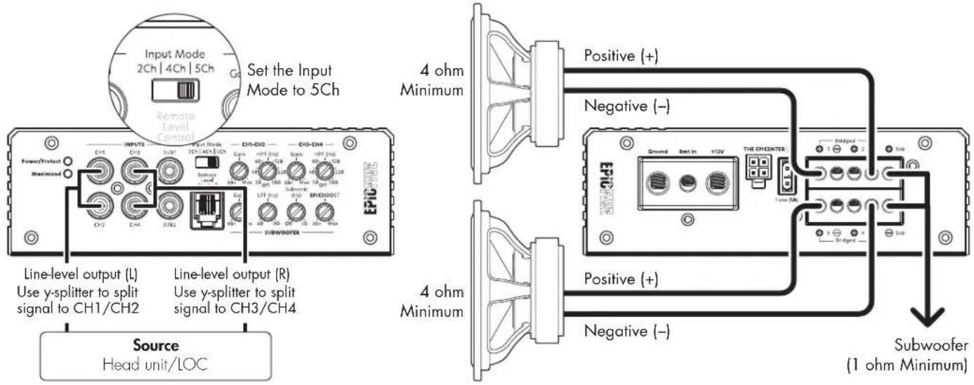
Input Mode – When connecting separate signal pairs to CH1/2, CH3/4, and SUB1/2, move this switch to 5Ch. When connecting separate signal pairs to CH1/2 and CH3/4 only, leaving the SUB1/2 inputs unused, move this switch to 4Ch. The subwoofer channel will receive signal from the CH1/2 inputs. When connecting only one signal pair, move this switch to the 2Ch position and connect the RCA pair to CH1/CH2. The EPICFIVE will route the signals from CH1/CH2 to all five channels.
-
Remote Level Control – Connect the included ACR-E remote level control and cable here.
-
Gain Control – Use this dial to match the source unit's output voltage with the inputs of amplifier. Remember, this is NOT a volume knob. With the source unit set to 75%, adjust this knob to the point where the Maximized light shines briefly. This will be your optimal gain setting.
-
High Pass Filter – A high pass filter allows you to match a speaker to the frequency range it is designed to handle. Choosing the high pass frequency recommended by the speaker manufacturer will provide increased speaker reliability and optimum sound quality. The EPICFIVE has 12 dB per octave active high pass filters with variable frequencies from 50 Hz to 500 Hz. The amplifier will output the frequency range above the selected high pass filter frequency. 80 Hz works well as a starting point for most systems.
-
Low Pass Filter – A low pass filter allows you to match a speaker to the frequency range it is designed to handle. Choosing the low pass frequency recommended by the speaker manufacturer will provide increased speaker reliability and optimum sound quality. EPIC Series amplifiers have a 12 dB per octave active low pass filter with variable frequencies from 40 Hz to 180 Hz. The amplifier will output the frequency range below the selected low pass filter frequency. 80 Hz works well as a starting point for most systems.
-
Subsonic Filter - The subsonic filter is a high pass filter designed to conserve amplifier power and protect subwoofers from extremely low frequencies. EPIC Series amplifiers have a subsonic filter with variable cutoff frequencies ranging from OFF to 50Hz . The subsonic filter is highly recommended for vented subwoofer enclosures with a recommended setting of 1/2 octave below the enclosure tunning frequency.
-
EPICBoost (Hz) – EPICBoost is a fixed frequency (45 Hz) bass equalizer with a boost range of 0 dB to +12 dB.
Smart Auto-Reset Protection – EPIC Series amplifiers feature a robust protection circuit to protect the amps from low/high voltage, unexpected short-circuits, or other potential electrical or thermal hazards. The Smart Auto-Reset Protection circuit offers the following protection:
Output Over-current Protection (OCP) Input Over-voltage Protection (OVP) Input Under-voltage Protection (UVP) Output DC-offset Protection (DCP) Over-Temperature Protection (OTP)
ACR-E Remote Level Control
ACR-E Remote (included) – The ACR-E remote level control allows you to control the volume of the EPIC Series monoblock amplifiers from the front of the vehicle. The remote acts as an attenuator, meaning when it is fully clockwise there is no change to the volume (as if there is no remote connected). Turning the knob counter-clockwise decreases the volume.
Installation – The ACR-E may be mounted under the dash using its own enclosure, or through a custom hole in the dash. The level control knob should be within reach of the driver, and in a spot where the LED is plainly visible. Ensure the amplifier is powered off when connecting the ACR-E.
Dash Bracket Installation – The ACR-E mounts with four screws, which attach to the underside of the dashboard. Slide under the dash and place the dash control in its mounting position, mark the mounting holes, drill pilot holes, and secure with four screws.
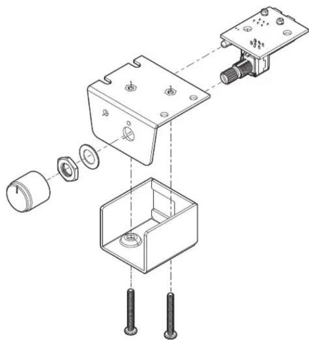
Custom Installation – ACR-E can be flush mounted directly on the dash/console panel (or anywhere else). Referencing the drawing right, disassemble the ACR-E. Drill a 9/32" (7 mm) hole in the panel for the control along with a 3/32" (2.3 mm) hole for the lock tab and a 1/8" (3 mm) hole for the LED. Reassemble the ACR-E components on the dashboard or console.

Important – AudioControl's ACR-1 remote is NOT compatible with EPIC Series amplifiers.
natural_image
Exploded view diagram of a mechanical assembly showing internal components and mounting features (no text or labels)AudioControl®
Making Good Sound Great™
Quick Start
Here are a few general steps to get your EPICFIVE five channel amplifier up and running:
- Undo the +12V and Ground connections to the vehicle battery before making any connections to the amplifier.
- Pick a mounting location that will provide access to the controls and connections, provide plenty of good ventilation, and protect the amplifier from hear, moisture, and dirt. Make sure the heat sink fins are not covered.
-
The EPICFIVE five channel amplifier needs to be securely mounted using the four mounting holes located in each corner.
-
Before drilling any holes, take every precaution to prevent any damage to fuel lines, power and other electrical wiring, hydraulic brake lines, and other systems that might compromise vehicle safety.
-
When making connections, designate red RCA plugs as right, and designate white, black, or gray plugs as left. This is a good idea for consistency.
-
Use quality interconnect cables.
-
Always connect the Ground terminal first before connecting the 12V power wire to the amp. NEVER REMOVE THE GROUND WIRE from the amp while the 12V wire is connected. Not following these instructions could result in damaging the amp and this would not be covered under warranty.
-
Connect the Ground terminal of the amplifier to a clean, solid ground in the vehicle, i.e. sheet metal. Use the shortest length possible of quality insulated wire of the recommended wire gauge (see specifications). Grind away any paint or coatings to ensure a clean, metal to metal contact. Use a sheet metal screw with a serrated flange, or a bolt and star washer.
- Connect the +12V terminal of the amplifier to the +12V terminal of the vehicle battery. Use the same gauge wire used for the Ground wire.

This wire must be fused close to the battery with an in-line fuse. See specifications for the recommended fuse rating.
-
Connect the remote power terminal of the amplifier to the remote turn-on output of your source unit.
-
Connect your source or line output converter (LOC) outputs to the amplifier.
-
Connect the ACR-E remote level control (included) to the Remote jack. Install the ACR-E in a location within easy reach so it can be safely adjusted.
-
Connect your loudspeakers (minimum impedance of 2 ohm or 4 ohms bridged, 1 ohm minimum for subwoofer channel only).
-
Set the crossovers to the frequency recommended by the loudspeaker manufacturer.
-
When all connections are made, reconnect the vehicle battery.
-
Adjust your gain settings to maximize your signal level.
-
Enjoy the drive!
Power Connections
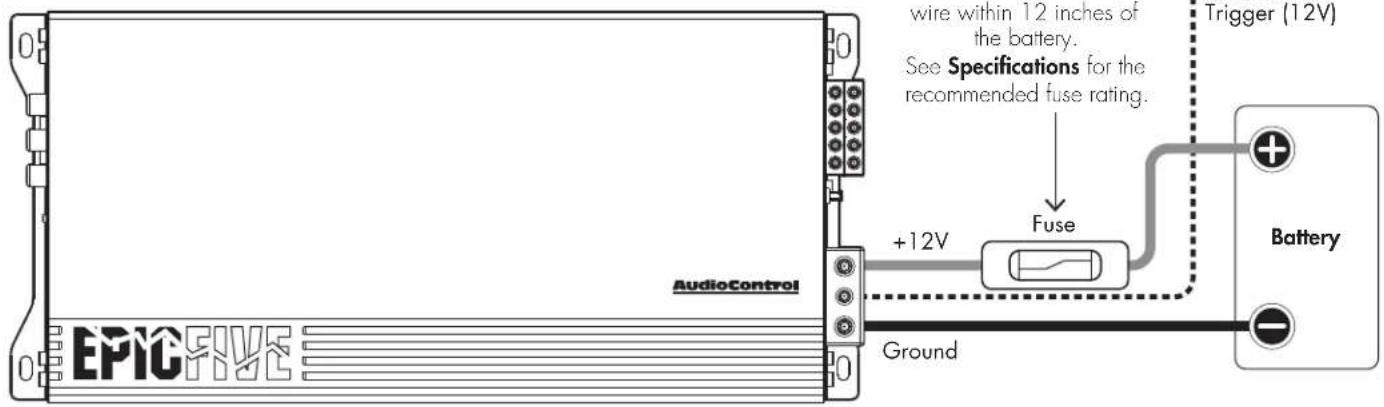
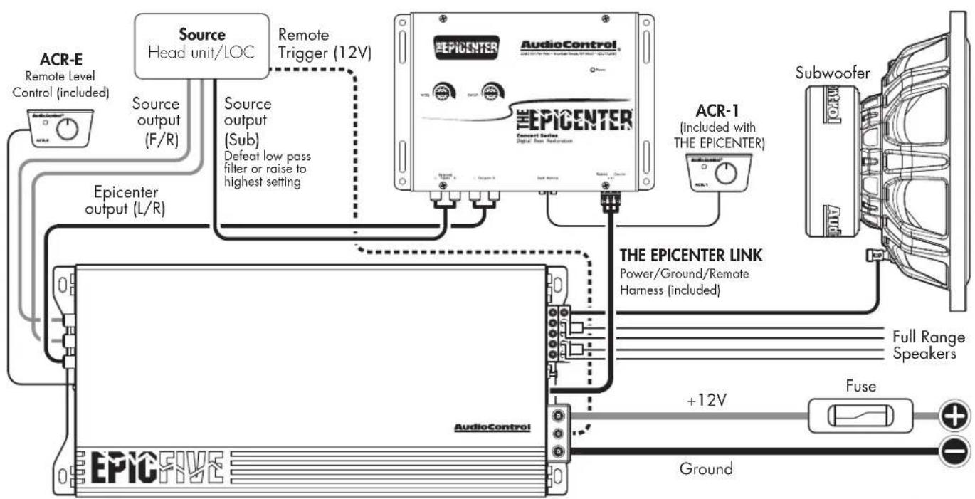
In this example, the source has a +12V trigger output that is connected to the EPICFIVE remote input terminal. When the head unit is turned on, it will turn on the amplifier.
Use the recommended gauge insulated wire for the +12V and Ground connections. An external fuse must be installed on the positive (+) wire. See specifications for the recommended fuse rating.
AudioControl®
Making Good Sound Great™
Audio Connections: Five Channel System
flowchart
graph TD
    A["ACR-E"] --> B["Line-level outputs*"]
    B --> C["Source Head unit/LOC"]
    C --> D["Input Mode 2Ch | 4Ch | 5Ch"]
    D --> E["Output: EPICFIVE"]
    E --> F["Ground"]
    G["Subwoofer"] --> H["Fuse"]
    H --> I["+12V"]
    I --> J["Ground"]
    K["Full range speakers"] --> H
    L["Input Mode 2Ch | 4Ch | 5Ch"] --> M["Output: EPICFIVE"]
    N["Input Mode 2Ch | 4Ch | 5Ch"] --> O["Output: EPICFIVE"]
    P["Input Mode 2Ch | 4Ch | 5Ch"] --> Q["Output: EPICFIVE"]
    R["Input Mode 2Ch | 4Ch | 5Ch"] --> S["Output: EPICFIVE"]
    T["Input Mode 2Ch | 4Ch | 5Ch"] --> U["Output: EPICFIVE"]
    V["*Set to 5Ch if you have separate signal pairs for (Front/Rear/Sub)"] --> W["Output: EPICFIVE"]
    X["*Set to 4Ch if you have two signal pairs (Front/Rear) but no sub signal"] --> Y["Output: EPICFIVE"]
    Z["*Set to 2Ch if you have one signal pair only connected to CH1/2"] --> AA["Output: EPICFIVE"]
Quick Start Guide
Adding THE EPICENTER®
flowchart
graph TD
    A["ACR-E\nRemote Level Control (included)"] --> B["Source\nHead unit/LOC"]
    B --> C["Source output\n(F/R)"]
    C --> D["Epicenter output (L/R)"]
    D --> E["AudioControl"]
    E --> F["AudioControl"]
    F --> G["Subwoofer"]
    G --> H["Subwoofer"]
    H --> I["The EPICENTER LINK\nPower/Ground/Remote Harness (included)"]
    I --> J["Fuse"]
    J --> K["Ground"]
    K --> L["+12V"]
    L --> M["Full Range\nSpeakers"]
    M --> N["AudioControl"]
    N --> O["EPICENTER"]
    O --> P["Concert Series\nDigital Base Retention"]
    P --> Q["Remote Trigger (12V)"]
    Q --> R["Source output\n(Sub)\nDefeat low pass filter or raise to highest setting"]
    R --> S["EPICENTER"]
    S --> T["AudioControl"]
AudioControl®
Making Good Sound Great™
Bridging Outputs
We said you weren't ready for this. AudioControl's EPICFIVE can output a conservative 300 watts RMS per channel at 4 ohms bridged plus up to 700 watts on the sub output (1Ω minimum). Set Input Mode to 5Ch. Connect the left channel of the source signal to the CH1/CH2 inputs using a y-splitter. Connect the right channel of the source signal to the CH3/CH4 inputs using a y-splitter. Connect the positive (+) output of channel 1 and the negative (-) output of channel 2 to the left speaker. Connect the positive (+) output of channel 3 and the negative (-) output of channel 4 to the right speaker. Connect a subwoofer to the sub output (1Ω minimum). Use the CH1/CH2 gain and HPF to adjust the left speaker, and CH3/CH4 gain and HPF to adjust the right speaker. Use the Subwoofer Gain, LPF, Subsonic Filter, and EPICBoost to adjust the sub. Yup, things just got EPIC!
Quick Start Guide
Built for THE EPICENTER®
EPIC Series amplifiers are designed for maximum, clean power output. When combined with AudioControl's original and best-selling digital bass restoration processor THE EPICENTER® or THE EPICENTER MICRO, the resulting bass will be... EPIC!
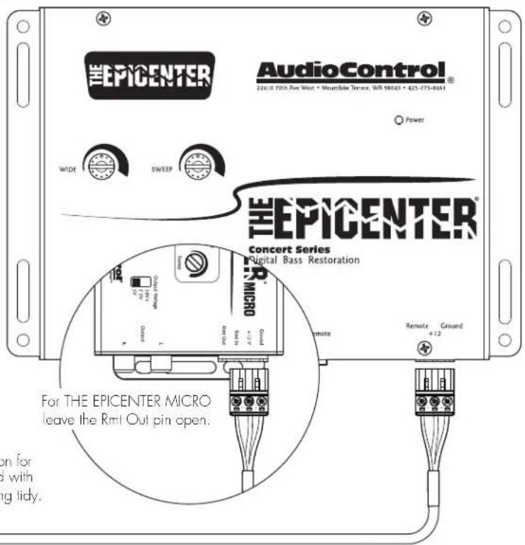
Keep your wiring tidy with THE EPICENTER LINK and supplied harness to provide power, ground, and remote signal to THE EPICENTER®.
THE EPICENTER ^® or THE EPICENTER ^® MICRO are not included.
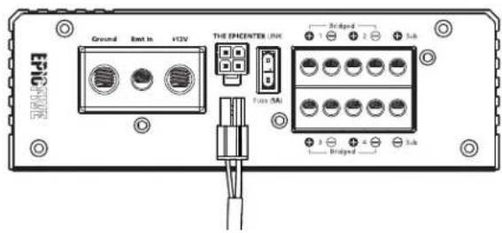
THE EPICENTER LINK
EPIC Series monoblock amplifiers provide power, ground, and remote turn on for THE EPICENTER or THE EPICENTER MICRO. A one meter harness is included with your amp to make this simple plug and play connection and keep your wiring tidy.
AudioControl®
Making Good Sound Great™
EPICFIVE Specifications
All specifications are measured at 14.4 VDC (standard automotive voltage). As technology advances, AudioControl reserves the right to continuously change our specifications, like our Pacific Northwest weather, although we are working on changing that as well.
Amplifier Topology ....Class D
Power Output RMS (14.4V, <1% THD) 4 x 75 Watts + 1 x 300 Watts @ 4 ohms
4 x 150 Watts + 1 x 500 Watts @ 2 ohms
.1 x 700 Watts @ 1 ohm (subwoofer output)
2 x 400 Watts @ 4 ohms Bridged
Frequency Response (+/- 1 dB)....10 Hz - 24 kHz (Ch1/2/3/4)
12 Hz - 181 Hz (Ch5)
S/N Ratio 92.1 dBa, Ref 75 Watts @ 4 ohms
Power / Ground Wire Gauge 4 AWG
Recommended Fuse Rating....150 Amps
High Pass Filter ..... 12dB/octave Linkwitz-Riley, Off, 50 Hz to 500 Hz
Low Pass Filter 12dB/octave Linkwitz-Riley, 40 Hz to 180 Hz
Subsonic Filter....12 dB/octave Linkwitz-Riley, Off to 50 Hz
EPIC Boost ...... Frequency Center: 45 Hz, Gain: 0 to 12 dB
Line-level Inputs 500mV - 6V RMS
Speaker Terminal Wire Gauge 8 AWG
Chassis Dimensions (LxWxH) 13.35 in. x 6.1 in. x 2.01 in.
.339 mm x 155 mm x 51 mm
Dimensions do not include connectors
What's in the box: EPICFIVE five channel amplifier, wrench, screws, ACR-E remote level control and cable, THE EPICENTER LINK (1 meter harness), manual
Warranty
In just the same way as walking into a room and seeing a big hairy spider on the wall, people are scared of warranties. Lots of fine print. Months of waiting around. Well, fear no more. This warranty is designed to make you rave about AudioControl. It's a warranty that looks out for you and your client, plus helps you resist the temptation to have your friend Sparky, who's "good with electronics," try to repair your AudioControl product. So go ahead, read this warranty, then register the information at www.audiocontrol.com/product-registration and include your comments.
Our warranty has conditional conditions! "Conditional" doesn't mean anything ominous. The Federal Trade Commission tells all manufacturers to use the term to indicate that certain conditions have to be met before they'll honor the warranty. If you meet all of these conditions, AudioControl will, at its discretion, repair or replace any AudioControl products that exhibit defects in materials and/or workmanship for one (1) year from the original date you bought it. We will repair or replace it, at our option, during that time.
Here are the conditional conditions:
- You must fully register your purchase within 15 days of the purchase date by going to the AudioControl product registration page at:
www.audiocontrol.com/product-registration
Failure to register your product will negate the warranty.
- You need to hold on to your sales receipt! All warranty service requires original sales receipt documentation. The warranty only applies to the original purchaser from an authorized AudioControl dealer.
Note: Products purchased from unauthorized dealers are not covered under warranty.
-
Our warranty covers AudioControl products that have been installed according to the instructions in this manual.
-
You cannot let anyone who isn't: (A) the AudioControl factory; or someone authorized in writing by AudioControl, service your AudioControl product. If anyone other than (A), or (B) messes with your AudioControl product, the warranty is void.
-
The warranty is void if the serial number is altered, defaced or removed, or if your product has been used improperly. Now that may sound like a big loophole, but here is what we mean by this: Unwarranted abuse is: (A) physical damage (don't use your product to pound in fence posts); (B) improper connections (120 volts into the amplifier terminals can fry the poor thing). This is the best product we know how to build, but for example, if you mount it to the front bumper of your car, drop it over Niagara Falls, or use it for anchoring your boat, something will go wrong.
Assuming you conform to 1 through 5, and it really isn't all that hard to do, we get the option of fixing your product, or replacing it with a new one, at our discretion.
In the event that your product is out of warranty or not covered under our warranty, you may request to have any damage repaired at our normal "Out of Warranty" repair cost.
See ya!
Quick Start Guide PN 915-041-0 Rev B
Brand : AudioControl
Model : Epic Five
Category : Receiver