
F-122C - Pregnant TOA - Free user manual and instructions
Find the device manual for free F-122C TOA in PDF.


| Product Type | Ceiling Mount Speaker |
| Enclosure Type | Bass Reflex |
| Rated Input (High Impedance) | 30 W |
| Power Handling (Continuous Pink Noise) | 60 W (8 Ω), 30 W (16 Ω) |
| Power Handling (Continuous Program) | 120 W (8 Ω), 60 W (16 Ω) |
| Impedance Options | 100 V line: 330 Ω (30 W), 1 kΩ (10 W), 3.3 kΩ (3 W), 10 kΩ (1 W); 70 V line: 170 Ω (30 W), 330 Ω (15 W), 1 kΩ (5 W), 3.3 kΩ (1.5 W), 10 kΩ (0.5 W); 25 V line: 170 Ω (3.7 W), 330 Ω (1.9 W), 1 kΩ (0.6 W), 3.3 kΩ (0.2 W), 10 kΩ (0.06 W); 8 Ω; 16 Ω |
| Sensitivity | 90 dB (1 W, 1 m) |
| Frequency Response (-10 dB) | 70 – 20,000 Hz |
| Frequency Response (-20 dB) | 50 – 20,000 Hz |
| Speaker Component | 12 cm (5") Cone Driver |
| Mounting Hole Diameter | 200 mm (7 7/8") |
| Maximum Ceiling Thickness | 37 mm (1 29/64") |
| Input Connector | Removable Locking Connector with Screw Terminals (2 Input + 2 Bridge) |
| Usable Cable | Solid Copper Wire: 0.5 – 1.6 mm (AWG 24–14); Stranded Copper Wire: 0.2 – 2.5 mm² (AWG 24–14) |
| Dimensions (Diameter x Depth) | 230 mm x 229 mm (9 1/16" x 9 1/64") |
| Weight | 3.7 kg (including accessories) |
| Finish (Grille) | Steel Plate, Painted White |
| Finish (Baffle) | Fire-Retardant ABS Resin, Black |
| Finish (Rim) | Fire-Retardant ABS Resin, Painted White |
| Supplied Accessories | Front Grille, Safety Wire (60 cm), Ceiling Reinforcement Ring, Paper Pattern |
| Optional Mounting Hardware | HY-TB1 Tile Bar Bridge, HY-TR1 Trim Ring, HY-AH1 Anchor Hanging Bracket, HY-BC1 Back Can |
| Overload Protection | Automatic Signal Cutoff (resets after ~10 seconds) |
| Recommended Equalizer | TOA AC-120 Electronic Controller or Digital Signal Processor with specified PEQ filters |
| Safety Features | Safety Wire Hook, Double-Locking Front Grille, Mounting Tabs with Screws |
| Repainting Instructions | Clean grille, spray thin coats of acrylic paint; do not use roller or brush |
Frequently Asked Questions - F-122C TOA
User questions about F-122C TOA
0 question about this device. Answer the ones you know or ask your own.
Ask a new question about this device
Download the instructions for your Pregnant in PDF format for free! Find your manual F-122C - TOA and take your electronic device back in hand. On this page are published all the documents necessary for the use of your device. F-122C by TOA.
USER MANUAL F-122C TOA
natural_image
Technical line drawing of a mechanical component or housing with no visible text or symbolsTABLE OF CONTENTS
- SAFETY PRECAUTIONS ...... 2
- GENERAL DESCRIPTION ...... 2
- FEATURES ...... 3
- NOMENCLATURE AND DIMENSIONS .... 3
- INSTALLATION 4
-
REMOVING THE SPEAKER FOR MAINTENANCE 9
-
REPAINTING THE SPEAKER .... 10
-
ABOUT THE INPUT OVERLOAD PROTECTION CIRCUITRY 10
-
ABOUT EQUALIZATION .... 10
-
SPECIFICATIONS 12
Accessories .... 12 Optional Components .... 12
Please follow the instructions in this manual to obtain the optimum results from this unit. We also recommend that you keep this manual handy for future reference.
1. SAFETY PRECAUTIONS
- Be sure to read the instructions in this section carefully before use.
- Make sure to observe the instructions in this manual as the conventions of safety symbols and messages regarded as very important precautions are included.
- We also recommend you keep this instruction manual handy for future reference.
Safety Symbol and Message Conventions
Safety symbols and messages described below are used in this manual to prevent bodily injury and property damage which could result from mishandling. Before operating your product, read this manual first and understand the safety symbols and messages so you are thoroughly aware of the potential safety hazards.

WARNING
Indicates a potentially hazardous situation which, if mishandled, could result in death or serious personal injury.

CAUTION
Indicates a potentially hazardous situation which, if mishandled, could result in moderate or minor personal injury, and/or property damage.

WARNING
- Leave the installation to your TOA dealer because the installation requires expert knowledge. Improper installation may cause the unit to fall, resulting in personal injury and/or property damage.
- Install the unit in a location that can structurally support the weight of the unit and its mounting hardware. Doing otherwise may result in the unit falling down and causing personal injury and/or property damage.
- Do not use other methods than specified to mount the unit. Extreme force is applied to the unit and the unit could fall off, possibly resulting in personal injuries.
- Attach the safety wire to the unit. If not attached, the unit could fall off, resulting in personal injury.
- Tighten each screw securely. Ensure that the unit has no loose joints after installation to prevent accidents that could result in personal injury.
-
Do not hold the diffuser as a handle to carry the unit. If the diffuser breaks off, the unit falls off, resulting in possible personal injury.
-
Use the specified mounting hardware in combination. Doing otherwise may cause the unit or component to fall off, resulting in personal injury.
-
Should the following irregularity be found during use, immediately stop operating the unit and contact your nearest TOA dealer. Further attempt to use under this condition may cause fire or electric shock.
-
If you detect smoke or a strange smell coming from the unit
· If no tone sounds

CAUTION
- Avoid installing the unit in humid or dusty locations, in locations exposed to the direct sunlight, near the heaters, or in locations generating sooty smoke or steam as doing otherwise may result in fire or electric shock.
- Do not operate the unit for an extended period of time with the sound distorting. This is an indication of a malfunction, which in turn can cause heat to generate and result in a fire.
- Avoid touching the unit's sharp metal edge to prevent injury.
2. GENERAL DESCRIPTION
The F-122C is a flush-mounted ceiling speaker that offers a wide frequency range and high-quality sound output. Use of its supplied and optional mounting hardware permits versatile mounting to match a wide range of applications and installation locations.
3. FEATURES
- Bass-reflex speaker system designed to provide a wide frequency range and high power handling capability.
- Wide-dispersion flush-mount ceiling speaker design employs unique acoustic construction to realize a wide area of coverage. Uniform sound output levels are achievable not only directly under the speaker, but also over a wide radius.
- Because the speaker is provided with both low- and high-impedance operating capability, it can be used in many different applications. Front panel-mounted input selector switch permits easy verification and change of current impedance settings, even after installation.
- Easy installation. Can be quickly and accurately mounted to ceilings and walls.
- Rotating front grille can be installed quickly and conveniently.
- Attractive exterior design specially created by an interior designer blends naturally with any architectural space, enhancing the immediate area's sense of harmony.
- Optional mounting hardware permits exposed installation or installation in weak ceiling panels.
4. NOMENCLATURE AND DIMENSIONS
[Front]
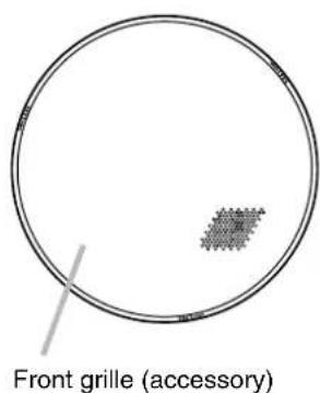
[Side]
![[Side] ø230 (9 1/16) 41 (1 39/64) 229 (9 1/64) ø195 (7 43/64) Approx. 600 (23 5/8) d clamp Safety wire (](/content/2026/05/958037/images/f9eec4694243c14f7032fe15c51ae4e00d38fc11c8c3bd45f3cc240da251855a.jpg)
Unit: mm (inches)
[Rear]
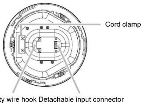
Safety wire hook Detachable input connector
[Ceiling mounting]
![Boiling mounting] Mounting hole: Ø200 (7 7/8) Ceiling reinforcement ring (accessory) Max. 37 (1 29/64) Max. 200 (7 7/8) Ceiling panel](/content/2026/05/958037/images/825bebc5086e746c3d0aaa6bbe19ea0713115f666612ba5ec4ff6afa5e421690.jpg)
5. INSTALLATION
The F-122C ceiling speaker can be mounted in 5 different configurations:
- Direct mounting to a ceiling panel
Use the supplied ceiling reinforcement ring. - Mounting to a ceiling frame
Use the supplied ceiling reinforcement ring in conjunction with the optional HY-TB1 Tile Bar Bridge. - Ceiling mounting in a larger than specified hole
Use the supplied ceiling reinforcement ring in conjunction with the optional HY-TR1 Trim Ring.
- Mounting to an anchor bolt
Use the supplied ceiling reinforcement ring in conjunction with the optional HY-AH1 Anchor Hanging Bracket.
- Hanging from a ceiling suspension pipe (exposed installation)
Use the optional HY-BC1 Back Can.
Mount the speaker using the most appropriate method for the ceiling panel or installation location.
Step 1. Cut a 200 mm (7 ^7/8 ") hole in the ceiling. Use the supplied paper pattern to position and trace the hole.

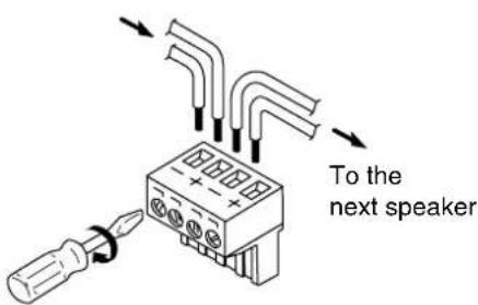
Step 2. Connect the speaker cable to the detachable input connector.
Tip
The following matching cable types are recommended:
- Solid copper wire: 0.5 - 1.6 mm (equivalent to AWG 24 - 14)
- Stranded copper wire: 0.2 - 2.5 ~mm^2 (equivalent to AWG 24 - 14)
2-1. Remove the detachable input connector from the speaker's wiring socket, and loosen the screw of the terminal to be used.
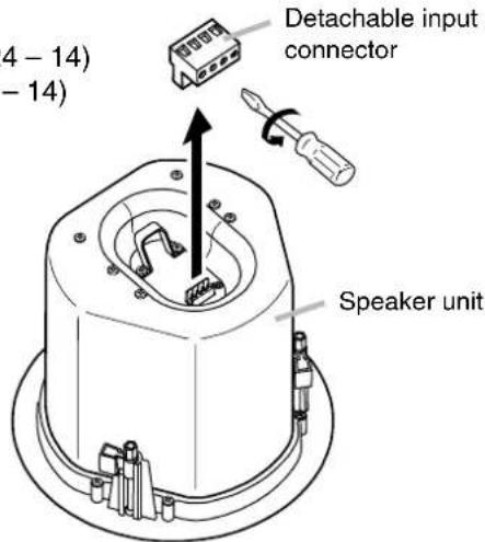
2-2. Insert the stripped cable end into the terminal and tighten the terminal screw with a screwdriver.
[If bridging][If not bridging]
Caution
If not making bridge connections, be sure to tighten unused terminal screws to avoid their vibration.
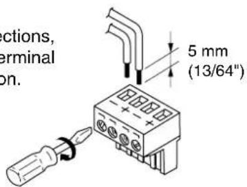
From Amplifier
Step 3. Mount fittings to a ceiling or hanging pipe.
3-1. Direct mounting to a ceiling panel
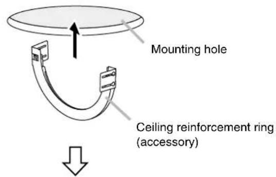
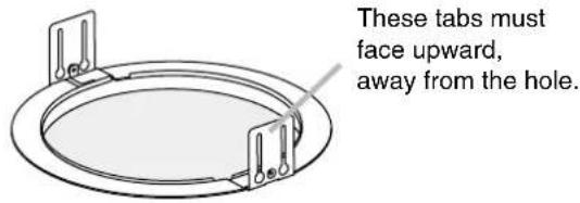
Fold the supplied ceiling reinforcement ring in half* and insert it through the mounting hole in the ceiling panel, then open it with its tabs facing up. Place the ring on the ceiling panel aligning it with the mounting hole.
* The reinforcement ring is too large to be inserted into the mounting hole unless folded.
Reinforcement ring placed on ceiling panel
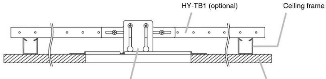
3-2. Mounting to a ceiling frame
Use the supplied ceiling reinforcement ring in conjunction with the optional HY-TB1 Tile Bar Bridge.
Note
Refer to the instruction manual included with the HY-TB1 for the correct ceiling mounting procedure.
[Installed HY-TB1]
Ceiling panelCeiling reinforcement ring (ac
3-3. Ceiling mounting in a larger than specified hole
Use the supplied ceiling reinforcement ring in conjunction with the optional HY-TR1 Trim Ring.
Note
Refer to the instruction manual included with the HY-TR1 for the correct ceiling mounting procedure.
[Installed HY-TR1]
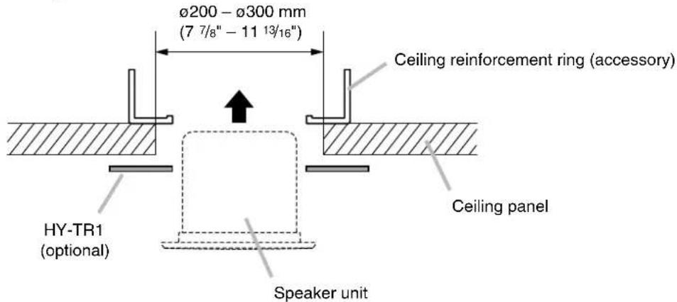
3-4. Mounting to an anchor bolt
Use the supplied ceiling reinforcement ring in conjunction with the optional HY-AH1 Anchor Hanging Bracket.
Note
Refer to the instruction manual included with the HY-AH1 for the correct mounting procedure.
[Installed HY-AH1]
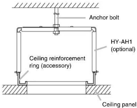
3-5. Hanging from a ceiling suspension pipe (exposed installation)
Use the optional HY-BC1 Back Can.
Notes
- The supplied ceiling reinforcement ring is not used.
- Refer to the instruction manual included with the HY-BC1 for Back Can installation.
[Installed HY-BC1]
(Example of mounting to suspension pipe)
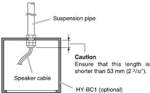
Step 4. Attach a safety wire to prevent the speaker from accidentally falling.
To attach, tie one end of the supplied safety wire around the speaker's safety wire hook, and tie its snap ring around a secure C-channel bar or suspension pipe.
[Flush ceiling mounting] [Exposed mounting]
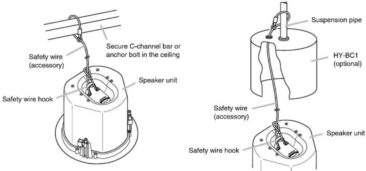
Step 5. Make speaker cable connection.
5-1. Plug the wired detachable input connector into the speaker's wiring socket.
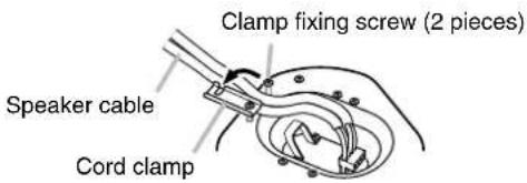
5-2. Fix the speaker cable with the cord clamp.
Loosen the cord clamp fixing screws and open the cord clamp. Then, pass the speaker cable between both screws.
Tighten the clamp fixing screws to fix the speaker cable with the cord clamp.
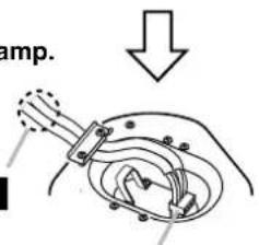
Confirm the connector will not pull out.
Pull on the cable here to confirm that speaker cable is securely fixed.
Detachable input connector
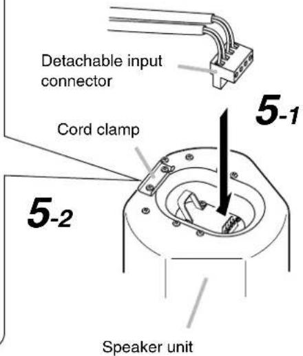
Step 6. Mount the speaker.
Caution
Before mounting, check to be sure that the speaker's 3 mounting tabs are turned inside the unit as shown in the figure. If turned outward, the speaker cannot be inserted through the mounting hole.
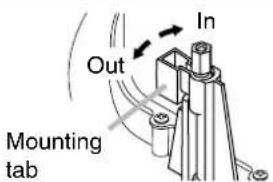
6-1. Flush ceiling mounting
(in the cases of Steps 3-1, 3-2, 3-3 and 3-4)
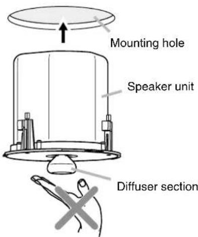
Insert the speaker through the mounting hole till it contacts the ceiling panel. While doing so, avoid directly touching the speaker's diffuser section.

WARNING
Never grab the diffuser section as a hand hold. The speaker could fall due to damage, resulting in possible personal injury.
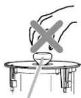
Diffuser section
Rotate and tighten the mounting tab axis screws (3 places) on the unit clockwise to their full stop in order to grip the ceiling panel with the mounting tabs.
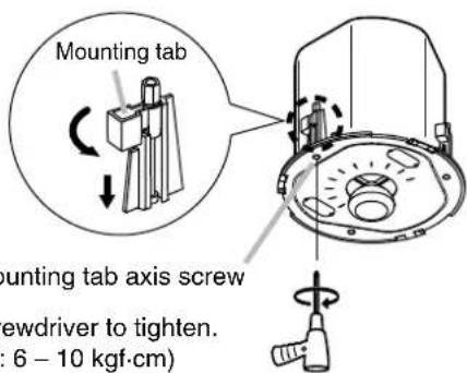
Use an electric screwdriver to tighten. (Tightening torque: 6 – 10 kgf·cm)
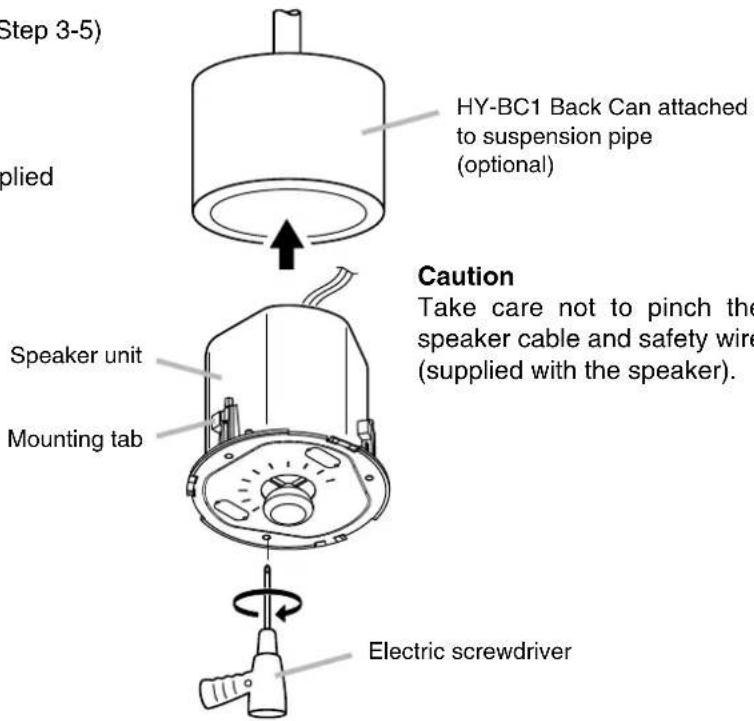
6-2. Exposed mounting (in the case of Step 3-5)
Follow Step 6-1 to mount.
Note
The ceiling reinforcement ring supplied with the speaker is not used.
Step 7. Set the input power.
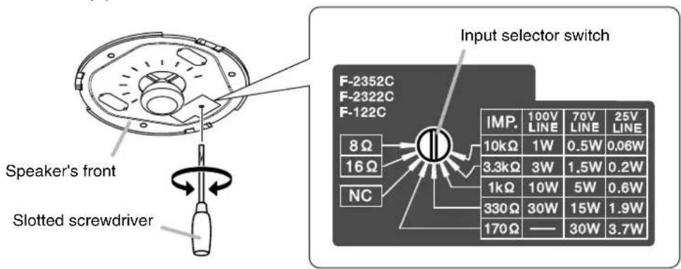
Turn the input selector switch (on the unit's front) to set it to the desired input impedance using a slotted screwdriver.
Note: The switch is factory-preset to 330 Ω.
Important
Never set this switch to low impedance (8 Ω or 16 Ω) when using a high impedance 25, 70, or 100 V line. Failure to follow this instruction could result in damage to the speaker or amplifier.
Step 8. Attach the front grille.
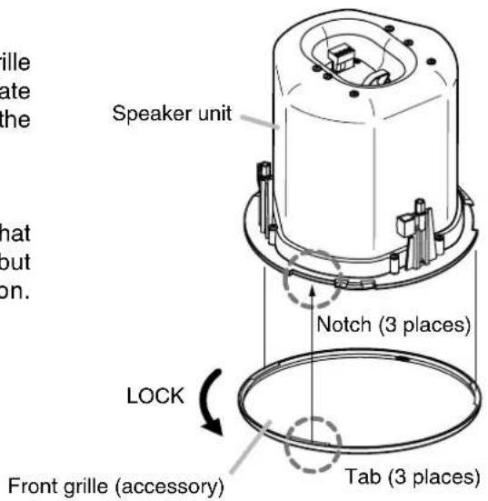
Align the tabs (3 places) on the back side of the grille with the corresponding notches in the unit, then rotate the grille to full stop in the direction indicated by the "LOCK" arrow.
Tip
The front grille employs a double-locking system that clicks into place once partway through rotation, but only locks into position at its point of full rotation. Always be sure to rotate the grille to its full stop.
6. REMOVING THE SPEAKER FOR MAINTENANCE
6.1. Detaching the Front Grille
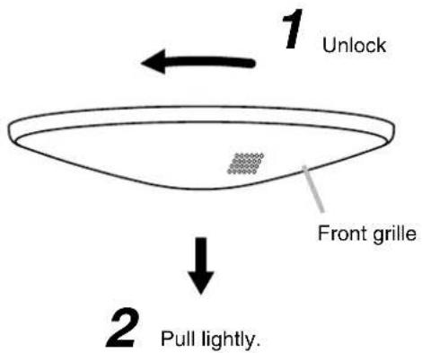
Turn the front grille counterclockwise to full stop, then lightly pull it downward.
Tip
The front grille employs a double-locking system.
If the grille cannot be detached when lightly pulled downward, it likely has not yet been fully rotated back to the detachment position. In such cases, take care to rotate the grill fully counterclockwise in order to release the lock.
6.2. Removing the Speaker
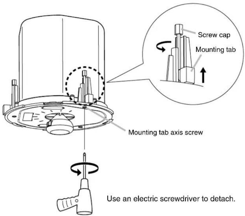
Rotate the 3 mounting tab axis screws counterclockwise. The mounting tabs rise as they turn, allowing the speaker to be removed.
Caution
When loosening the mounting tab axis screws, support the speaker by hand to prevent it from falling.
Caution
Be sure to set the screwdriver's torque for under 4 kgf·cm.
Failure to do so may cause the Screw cap and the Mounting tab to fall off on the rear of ceiling panel.
7. REPAINTING THE SPEAKER
Follow the procedure below when repainting the front grille:
Step 1. Clean the front grille before painting.
Wipe with a soft cloth dampened in a detergent.
Caution
Do not use thinner or other volatile liquids to clean the grille.
Step 2. Spray on a uniform, thin coat of paint.
Cautions
- Avoid painting with a roller or brush, as the grille mesh holes could become clogged with paint.
- Use appropriate spray paints for the front grille (grille and frame) materials.
Grille: Rolled steel plate
Frame: Fire-resistant ABS resin (acrylic paint) - Be sure to follow the directions indicated on the paint when painting.
Step 3. After the paint has dried, apply another light coat.
Caution
Repeating Step 2, apply two or more light coats of paint.
Application of one thick coat of paint all at once may cause drips or unevenness to show up in the painted finish, or clog the mesh holes.
8. ABOUT THE INPUT OVERLOAD PROTECTION CIRCUITRY
The F-122C features internal input overload protection circuitry. If an extremely high input level is fed to the unit, the protection circuitry automatically cuts off the signal to the speaker element.
A drastic reduction in sound volume indicates that the protection circuitry has been enabled.
In such cases, simply reduce the amplifier volume. The protection circuitry will automatically reset in approximately 10 seconds. After reset, try to maintain the volume at a level slightly lower than before.
Caution
This protection circuitry does not completely protect the unit against extremely high input power levels. Depending on the type or duration of excessive power input, the protection circuitry might not be enabled, resulting in damage to the speaker element. Also, if the excessive power input continues for a long period of time, the circuitry may not be capable of resetting to its original condition.
Use the system with care so that the speakers are not exposed to excessive power input.
9. ABOUT EQUALIZATION
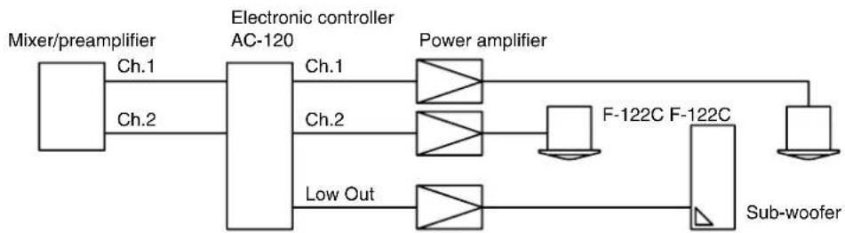
9.1. Using the AC-120 Electronic Controller (optional)
The dedicated AC-120 is required to use the F-122C speaker.
It features the most appropriate equalization filter for the F-122C.
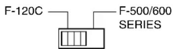
Note
Set the AC-120's mode switch to F-120C position.
[System employing no sub-woofer]

[System employing a sub-woofer]
9.2. Using TOA's Digital Signal Processor
When using TOA's digital signal processor instead of the AC-120, it is recommended that frequency characteristics be set as shown in the following tables:
Filter characteristics for F-122C (normal mode) (Setting for ordinary applications)
| Filter Frequency Gain Q | |||
| PEQ 85 Hz +11.5 dB 2.871 | |||
| 212 Hz -2.5 dB 0.667 | |||
| 900 Hz -8 dB 2.871 | |||
| 10 kHz +8 dB 0.267 | |||
| HPF 37.5 Hz | — | 0.7 | |
| 12dB/oct. 37.5 Hz | — | 0.5 | |
| LPF 20 kHz | — | 0.7 | |
| 12dB/oct. | |||
Filter characteristics for F-122C (low-frequency cut mode) (Setting for speech applications or with a subwoofer)
| Filter Frequency Gain Q | |||
| PEQ 80 Hz +6.5 dB 1.414 | |||
| 180 Hz -4.5 dB 0.667 | |||
| 900 Hz | -8 dB 2.871 | ||
| 11.2 kHz | +8 dB 0.267 | ||
| HPF12dB/oct. 45 Hz | 45 Hz | —— | |
| —— | 0.7 | ||
| LPF12dB/oct. | 20 kHz | —— | |
Filter characteristics for sub-woofer
| Filter Frequency Gain Q | |||
| PEQ | 112 Hz | +2.5 dB | 0.667 |
| LPF 12dB/oct. | 100 Hz | — | 0.5 |
Note
Set the F-122C's filter characteristic to Low-Frequency Cut mode when used in combination with a sub-woofer.
10. SPECIFICATIONS
| Enclosure Bass reflex type | |
| Rated Input 30 W (High Impedance) | |
| Power Handling Capacity | Continuous pink noise: 60 W (8 Ω), 30 W (16 Ω)Continuous program: 120 W (8 Ω), 60 W (16 Ω) |
| Impedance | 100 V line: 330 Ω (30 W), 1 kΩ (10 W), 3.3 kΩ (3 W), 10 kΩ (1 W)70 V line: 170 Ω (30 W), 330 Ω (15 W), 1 kΩ (5 W), 3.3 kΩ (1.5 W), 10 kΩ (0.5 W)25 V line: 170 Ω (3.7 W), 330 Ω (1.9 W), 1 kΩ (0.6 W), 3.3 kΩ (0.2 W), 10 kΩ (0.06 W)16 Ω, 8 Ω |
| Sound Pressure Level 90 dB (1 W, 1 m) | |
| Frequency Response | 70 – 20,000 Hz (-10 dB), 50 – 20,000 Hz (-20 dB)at installation in 1/2 free sound field(Measured by installing the unit in the center of a ceiling.) |
| Speaker Component | 12 cm (5") cone-type |
| Mounting Hole | ø200 mm ( 7^7/_8 ")Maximum ceiling thickness: 37 mm ( 1^29/_64 ") |
| Input Terminal | Removable locking connector with screw-down terminals(2 input terminals and 2 bridge terminals) |
| Usable Cable | Solid copper wire: ø0.5 – ø1.6 mm (equivalent to AWG 24 – 14)Stranded copper wire: 0.2 – 2.5 mm^2 (equivalent to AWG 24 – 14) |
| Finish | Enclosure: Steel plate, platingBaffle: Fire-resistant ABS resin (resin material grade: UL-94 V-0 or its equivalent), blackRim: Fire-resistant ABS resin (resin material grade: UL-94 V-0 or its equivalent), white, paintPunched net: Steel plate, white, paint |
| Dimensions ø230 mm (9 | ^1/_16 ") x Depth 229 mm ( 9^1/_64 ") |
| Weight | 3.7 kg (including mounting accessories) |
Note: The design and specifications are subject to change without notice for improvement.
- Accessories
Front grille 1
Safety wire (approx. 60 cm or 23 ^5/8 ) ...... 1
Ceiling reinforcement ring 1
Paper pattern 1
- Optional Components
HY-TB1 (Tile Bar Bridge): Place this bridge on the ceiling frame when mounting the speaker unit to a weak suspended ceiling.
HY-TR1 (Trim Ring): Use this ring when mounting the speaker in pre-existing holes that are larger than the designated 200 mm ( 7^7/_8 ) in diameter.
HY-AH1 (Anchor Hanging Bracket): Attach this bracket to an anchor bolt when mounting the speaker unit to a weak ceiling.
HY-BC1 (Back Can): Use this Back Can when mounting the speaker unit in exposed hanging applications.
Traceability Information for Europe
| Manufacturer: |
| TOA Corporation |
| 7-2-1, Minatojima-Nakamachi, Chuo-ku, Kobe, Hyogo, Japan |
| Authorized representative: |
| TOA Electronics Europe GmbH |
| Suederstrasse 282, 20537 Hamburg, Germany |
- TABLE OF CONTENTS
- SAFETY PRECAUTIONS
- Safety Symbol and Message Conventions
- WARNING
- CAUTION
- GENERAL DESCRIPTION
- FEATURES
- NOMENCLATURE AND DIMENSIONS
- INSTALLATION
- Tip
- From Amplifier
- 3-1. Direct mounting to a ceiling panel
- 3-2. Mounting to a ceiling frame
- Note
- 3-3. Ceiling mounting in a larger than specified hole
- 3-4. Mounting to an anchor bolt
- 3-5. Hanging from a ceiling suspension pipe (exposed installation)
- Notes
- Step 4. Attach a safety wire to prevent the speaker from accidentally falling.
- Confirm the connector will not pull out.
- 6-1. Flush ceiling mounting
- 6-2. Exposed mounting (in the case of Step 3-5)
- Step 7. Set the input power.
- Important
- Step 8. Attach the front grille.
- REMOVING THE SPEAKER FOR MAINTENANCE
- Detaching the Front Grille
- Removing the Speaker
- REPAINTING THE SPEAKER
- Cautions
- ABOUT THE INPUT OVERLOAD PROTECTION CIRCUITRY
- ABOUT EQUALIZATION
- Using the AC-120 Electronic Controller (optional)
- Using TOA's Digital Signal Processor
- SPECIFICATIONS
- - Accessories
- - Optional Components
Brand : TOA
Model : F-122C
Category : Pregnant