
CA-R-SSR.005 - Automotive wiring PIONEER - Free user manual and instructions
Find the device manual for free CA-R-SSR.005 PIONEER in PDF.


| Product Type | Car Audio Accessory |
| Model Number | CA-R-SSR.005 |
| Brand | Pioneer |
| Compatibility | Compatible with most Pioneer car stereos |
| Dimensions (approx.) | 4.5 x 2.0 x 1.0 inches |
| Weight | 0.1 lb (45 g) |
| Power Source | 12V DC (car battery) |
| Power Consumption | 0.5 W (standby), 2 W (active) |
| Primary Functions | Remote control for car audio, volume adjustment, track selection |
| Connectivity | Wired connection via 3.5mm jack or proprietary port |
| Cable Length | 3.3 ft (1 m) |
| Material | Plastic casing, rubberized buttons |
| Color | Black |
| Operating Temperature | -20°C to 60°C |
| Storage Temperature | -30°C to 70°C |
| Certifications | CE, FCC |
| Maintenance & Cleaning | Wipe with dry cloth; avoid liquids |
| Safety Precautions | Do not expose to moisture or extreme heat |
| Spare Parts & Repairability | Non-repairable; replace if defective |
| Warranty | 1 year limited |
Frequently Asked Questions - CA-R-SSR.005 PIONEER
User questions about CA-R-SSR.005 PIONEER
0 question about this device. Answer the ones you know or ask your own.
Ask a new question about this device
Download the instructions for your Automotive wiring in PDF format for free! Find your manual CA-R-SSR.005 - PIONEER and take your electronic device back in hand. On this page are published all the documents necessary for the use of your device. CA-R-SSR.005 by PIONEER.
USER MANUAL CA-R-SSR.005 PIONEER
Steering wheel control interface installation kit for:
SSANGYONG
Model: Rexton only for vehicles with dual camera
Year: 2016>
Kit content: SWC Resistive interface wiring harness camera adapter voltage stabilizer radio adapter(*) if included
Customer code:
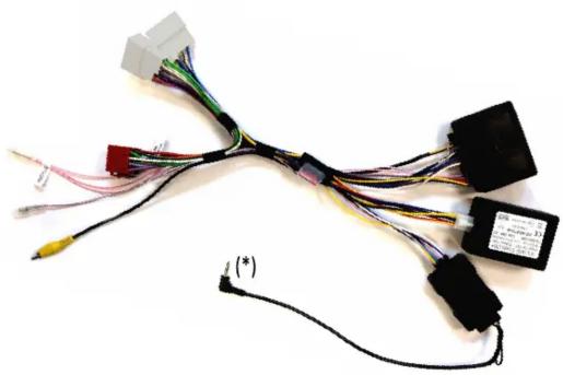
natural_image
Coiled electrical connector with various wires and components, no visible text or symbolsINSTALLATION MANUAL
All installation work must be performed by a qualified professional installer only.
The manufacturer / dealer is not liable for any kind of incidental or indirect damages.
10/2016 ALL RIGHTS RESERVED. Technical changes possible. No liability for misprints.R0
All installation work must be performed by a qualified professional installer only.
The manufacturer / dealer is not liable for any kind of incidental or indirect damages.
10/2016 ALL RIGHTS RESERVED. Technical changes possible. No liability for misprints.

natural_image
Electrical wiring diagram showing connections between components including wires, connectors, and a terminal block (no text or symbols visible)ATTENTION!
In order to prevent ESD damage, the WHEEL REMOTE JACK must be connected before plugging in the connectors on car side.
Connect cables to the radio side as follow:
1- to ISO CONNECTORS (black and red housings)
2- to WIRED REMOTE SOCKET (NOTE: do not connect to microphone socket)
3- to SERVICES (if required); function is marked on the wire:
Pink - Speed
Violet/White - Reverse
4- to CAMERA CONNECTOR
Connect cables to the car side as follow:
5- to CAR CONNECTOR

The steering wheel buttons perform the following functions (if supported by the radio):
1- Volume +
2- Volume -
3- Short Press (<0,5 Secs) = Mute
Long Press (>0,5 Secs) = Reject incoming call *
4- Seek down
5- Source
6- Seek up
7- Short Press (<0,5 Secs) = Accept incoming call
Long Press (>0,5 Secs) = Voice *
8- Front camera **
* NOTE: depending on the radio model, the activation time of this function could take up to 3 seconds.
** NOTE: due to safety reasons, the front camera is available only at low speed.
Brand : PIONEER
Model : CA-R-SSR.005
Category : Automotive wiring