
T103 - Digital Timer INTERMATIC - Free user manual and instructions
Find the device manual for free T103 INTERMATIC in PDF.


| Product Type | Digital Timer |
| Brand | Intermatic |
| Model | T103 |
| Contact Configuration | Double Pole Single Throw (DPST) |
| Contact Rating | 40 A Resistive, Inductive, Tungsten or 1000 VA Pilot Duty per pole (120/208/240 VAC); 2 HP (24 FLA) @ 120 VAC, 5 HP (28 FLA) @ 240 VAC; 16 A Electronic Ballast @ 277 VAC |
| Clock Motor Voltage | 120 VAC, 60 Hz |
| Wire Requirements | Solid or stranded COPPER conductors only, minimum 90°C insulation, remove 1/2 inch insulation, tighten screws 2-18 in-lbs |
| Minimum Copper Wire Size | 14 AWG for 15 A, 12 AWG for 20 A, 10 AWG for 30 A, 8 AWG for 40 A |
| Maximum Motor Load (Single Phase) | 1/2 HP @ 120 V, 2 HP @ 240 V (14 AWG); 1 HP @ 120 V, 2 1/2 HP @ 240 V (12 AWG); 2 HP @ 120 V, 3 HP @ 240 V (10 AWG); - @ 120 V, 5 HP @ 240 V (8 AWG) |
| Programming Method | Trippers set ON/OFF times by holding against clock-dial edge and tightening screws; additional trippers available (156T1978A) |
| Time-of-Day Setting | Pull clock-dial outward, turn to align current time with pointer |
| Manual Override | Move manual lever left or right below clock-dial |
| Power Failure Recovery | Reset clock-dial to proper time-of-day after power restores |
| Safety Warnings | Disconnect power before installation/service; use copper conductors only; replace plastic insulator before powering on; keep door closed when not servicing; rotate timer dial clockwise only; do not move clock hands |
| Certifications | C US, UL listed (LR3730) |
| Replacement Parts | Order by part number (WG--) on motor cover for clock motor |
Frequently Asked Questions - T103 INTERMATIC
User questions about T103 INTERMATIC
0 question about this device. Answer the ones you know or ask your own.
Ask a new question about this device
Download the instructions for your Digital Timer in PDF format for free! Find your manual T103 - INTERMATIC and take your electronic device back in hand. On this page are published all the documents necessary for the use of your device. T103 by INTERMATIC.
USER MANUAL T103 INTERMATIC
DOUBLE POLE SINGLE THROW (DPST)
40 A RESISTIVE, INDUCTIVE, TUNGSTEN
OR 1000 VA PILOT DUTY EACH POLE 120/208/240 VAC
2 HP (24 FLA) - 120 VAC; 5 HP (28 FLA) - 240 VAC
16 A ELECTRONIC BALLAST, 277 VAC

C US
LR3730
UL
HOLOGRAM
LABEL

WARNING Risk of Fire or Electric Shock
- Disconnect power at the circuit breaker(s) or disconnect switch(es) before installing or servicing.
• Installation and/or wiring must be in accordance with national and local electrical code requirements. - Use wires rated at least 90^ - COPPER conductors ONLY.
- Replace plastic insulator covering terminals before powering ON.
- KEEP DOOR CLOSED AT ALL TIMES when not servicing.

- Rotate timer dial clockwise only.
- Do not move the clock hands on the timer. Moving the clock hands can damage the timer.
CLOCK MOTOR: 120 VAC, 60 HZ.
CLOCK MOTOR VOLTAGE AND CYCLE MUST BE AS SPECIFIED. TO ORDER REPLACEMENT, INDICATE PART NO. (WG--) ON MOTOR COVER.
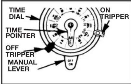
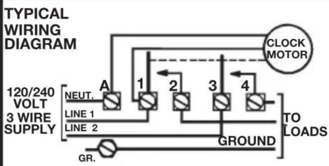
WIRING INSTRUCTIONS: Remove 1/2 inch of insulation from wire ends. Tighten terminal screws firmly (2-18 in-lbs). Use solid or stranded COPPER conductors only. May use two wires of the same size and type.
| MINIMUM COPPER WIRE SIZE (AWG) | MAX. LOAD (AMP) | MIN. INSULATION TEMP(°C) | 75°C INSULATION MAX. MOTOR LOAD (HP) | |||
| SINGLE PHASE | 3 PHASE | |||||
| 120 V. 240 V. 208 V. | 240 V. | |||||
| 14 | 15 | 90 | 1/2 | 2 | N/A | N/A |
| 12 | 20 | 90 | 1 | 2 1/2 | ||
| 10 | 30 | 90 | 2 | 3 | ||
| 8 | 40 | 90 | - | 5 | ||
natural_image
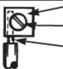
Pure mechanical diagram showing a lever and lever assembly without any text, numbers, or symbolsPRESSURE PLATE
TERMINAL SCREW
MAKE SURE WIRE INSULATION CLEARS PRESSURE PLATE
PROGRAMMING INSTRUCTIONS
- TO SET "ON" AND "OFF" TIMES: Hold trippers against edge of CLOCK-DIAL, pointing to time (AM or PM) when ON and OFF operations are desired, tighten tripper screws firmly. For additional tripper pairs on CLOCK-DIAL order 156T1978A.
- TO SET TIME-OF-DAY: Pull CLOCK-DIAL outward. Turn in either direction and align the exact time-of-day on the CLOCK-DIAL (the time now, when switch is being put into operation) to the pointer. DO NOT MOVE POINTER.
OPERATING INSTRUCTIONS
• TO OPERATE SWITCH MANUALLY: Move MANUAL LEVER below CLOCK-DIAL left or right as indicated by arrows. This will not effect next operation.
- IN CASE OF POWER FAILURE, reset CLOCK-DIAL to proper time-of-day. See programming instructions.
Brand : INTERMATIC
Model : T103
Category : Digital Timer