
F 445 Holliday CF - Heating JOTUL - Free user manual and instructions
Find the device manual for free F 445 Holliday CF JOTUL in PDF.


| Product Type | Wood Stove |
| Brand | Jøtul |
| Model | F 445 Holliday CF |
| Fuel Type | Solid natural wood only |
| Dimensions (H x W x D) | 26.25 in. x 29 in. x 25 in. |
| Heat Output Range | 13,726 to 35,722 Btu/hr (4.0-10.5 kW) |
| Maximum Heat Output | 55,000 Btu/hr |
| Heating Capacity | Up to 1,600 sq. ft. |
| Maximum Burn Time | Up to 9 hours |
| EPA Efficiency | HHV: 72%, LHV: 78% |
| CO Emissions | 0.60 g/min |
| Particulate Emissions | 0.49 g/hr |
| Maximum Log Length | 20 in. (508 mm) |
| Chimney Connector Diameter | 6 in. (152 mm) |
| Chimney Height Requirement | Minimum 15 ft. (4.57 m) |
| Floor Protection Required | Yes, UL 1618 listed non-combustible material |
| Mobile Home Approved | Yes (with floor bracket and outside air kit) |
| Catalytic Combustor | Yes, Jøtul High Flow (replaceable) |
| Warranty | Limited lifetime (baffle/air manifold), 5 years (cast iron/steel), 2 years (enamel), 1 year (electrical) |
Frequently Asked Questions - F 445 Holliday CF JOTUL
User questions about F 445 Holliday CF JOTUL
0 question about this device. Answer the ones you know or ask your own.
Ask a new question about this device
Download the instructions for your Heating in PDF format for free! Find your manual F 445 Holliday CF - JOTUL and take your electronic device back in hand. On this page are published all the documents necessary for the use of your device. F 445 Holliday CF by JOTUL.
USER MANUAL F 445 Holliday CF JOTUL
| Jøtul F 445 Holliday |  | HollidayInstallation and Operating Instructions for the United States and Canada |
 | The Jøtul F 445 wood stove is listed to burn solid wood only. Do not burn any other fuels.Read this entire manual before you install and use this appliance.Save these instructions for future reference and make them available to anyone using or servicing this wood heater.This wood heater contains a catalytic combustor that requires periodic inspection and maintenance for proper operation. See this manual for specific maintenance information. It is against federal regulations to operate this wood heater in a manner inconsistent with the operating instructions in this owner's manual, or if the catalytic element is deactivated or removed.Une version française de ce manuel est disponible auprès de votre revendeur et sur le site www.jotul.ca. |
Holliday
Table of Contents
Combustion Specifications,
Building Codes,
Safety Notices 3-4
1. Installation
1.1 Assembly before Installation 5
2. Chimney and Connector Requirements
2.1 Chimney Connector 6
2.2 General Requirements 6
2.3 Masonry Chimneys 7
2.4 Prefabricated Chimneys 8
2.5 Chimney Height 8
2.6 Wall Pass-through 8
3. Connecting to the Chimney
3.1 Masonry Chimney Thimbles 9
3.2 Hearthmount into a Masonry Fireplace 10
3.3 Prefabricated Chimneys 10
4. Clearances to Combustibles
4.1 Floor Protection 11
4.2 Alternate Floor Protection .... 11
4.3 Clearances to Walls and Ceilings 12
4.4 Using Shields to reduce Clearances .....12
4.5 Alcove Installation 13
Clearance Charts ....14-15
4.6 Mobile Home Installation 16
5. Operation
5.1 Combustion Efficiency .....16
5.2 CO Emissions 17
5.3 Wood Fuel and Performance .....17
5.4 Stove Control - Functions and Settings .....18
5.5 Stove Top Thermometer 19
5.6 Using the Combustor Monitor ....19
5.7 Stove Break-in Procedure 20
5.8 Starting and Maintaining a Fire 21
5.9 Creosote Formation and Removal 21
5.10 Adding Fuel 22
6. Maintenance
6.1 Annual Stove Inspection 22
6.2 Ash Removal 22
6.3 Chimney System 22
6.4 Enamel Care ....23
6.5 Glass Care/Glass Replacement 23
6.6 Gaskets....23
6.7 Combustion System Maintenance ....24
6.8 Combustor Replacement 24
7. Parts Lists
Exploded Diagram ......26
Part Numbers ......27
- Warranty.... 28-29
Accessories
The following accessories, specifically designed for the Jøtul F 445 wood stove, are available from your Jøtul authorized dealer.
Rear Heatshield - 158374
A stove rear heatshield has been specifically designed for the Jøtul F 445 to reduce clearances off the rear of the stove to combustible materials. Use of the heatshield does not affect the clearance off the sides of the appliance.
See pages 14-15 for specific clearance requirements. Complete installation instructions are supplied with the heatshield.
No other type of heatshield may be used.
Blower Kit - 156431
This thermostatically-controlled, 120 cfm blower mounts unobtrusively to the back of the stove to quietly enhance heat convection to the living area. The kit includes installation and operation instructions and must be installed with Rear Heat Shield 158374, not included in Blower Kit.
Outside Air Kit - 154335
Provision for outside air may be required by your local building codes.
The outside air kit includes a 3 inch adapter used to connect an air duct directly to the stove combustion chamber. The following additional materials will be required:
A. The appropriate length of metallic flex pipe for a conduit of the outside air.
B. A rain/weather resistant cap for the outside of the house.
C. A rodent screen - that is no larger than 1/4"(6,4mm) mesh.
Follow the instructions provided with the kit.
Please be aware that provision of outside air to support combustion will not necessarily eliminate performance issues associated with negative pressure within the home or chimney system.
Floor Bracket Kit - 750304
Use of the floor bracket kit is required in all mobile home installations to secure the stove to the floor.
Stove-top Thermometer - 5002
You can use a magnetic stove-top thermometer in conjunction with the catalytic combustor monitor to help achieve optimal stove performance.
Short Leg Kit - #350074 This kit includes four, 4 1/4" cast iron legs which reduce stove height by 2 1/4". Use of short leg kit
requires a 1.6 R value hearth pad.
Leg Leveler Kit - 156096
Stove Gloves, pair - 157363
Heavy duty, flame retardant, with full gauntlet.
Universal Gasket Kit - 157050
This kit includes all the gasket material and instructions required to maintain the seal integrity of your wood stove.
Replacement Catalyst - 158287
Combustion Monitor - 226609
Standards
The Jøtul F 445 Holliday solid fuel heater has been tested and listed to ANSI/UL 1482 in the U.S. and ANSI CAN/ULC-S627 and CAN/ULC 628 in Canada. Certified Safety Tests performed by Intertek Testing Services, Middleton, WI U.S.A.
Manufactured by
Jøtul North America, Inc.
55 Hutcherson Drive
Gorham, Maine 04038, U.S.A.
This heater meets the 2020 U.S. Environmental Protection Agency's emission limits for wood heaters manufactured after May 15, 2020.
This manual describes the installation and operation of the Jøtul F 445 catalytic equipped wood heater. This heater meets the 2020 U.S. Environmental Protection Agency's crib wood emission limits for wood heaters sold after May 15, 2020. Under specific test conditions, this heater has been shown to deliver heat at rates ranging from 13,726 to 35,722 Btu/hr.
Check Building Codes
Your city, town, county or province may require a building permit to install a solid fuel burning appliance.
In the U.S., the National Fire Protection Association's Code, NFPA 211, Standards for Chimneys, Fireplaces, Vents and Solid Fuel Burning Appliances, or similar regulations, may apply to the installation of a solid fuel burning appliance in your area.
Always consult your local building inspector or authority having jurisdiction to determine what regulations apply in your area.
Combustion Specifications
Heat Output Range: ^1 13,726 to 35,722 BTU/hr. (4.0-10.5 kW)
Max Heat Output:
55,000 BTU
Heating Capacity: ^2 Up to 1600 sq. ft.
Maximum Burn Time: ^2 Up to 9 hours
EPA Efficiency: ^3 HHV: 72%* LHV: 78%
CO Emissions: ^4
.60 g/min.
Particulate Emissions: ^5 .49 g/hr.
Fuel: Up to 20" Logs (508 mm)
1 Heat Output Range results are determined during specific emissions tests established by the EPA.
2 Heating Capacity and Maximum Burn Time will vary depending on design of home, chimney, climate, wood type and operation.
3 EPA Validated Efficiency:
High Heat Value and Low Heat Value efficiencies are determined per the CSA B415.1-10 test method. The difference between the HHV and LHV is how the energy in the exhaust gas water vapor is accounted for.
LHV efficiency assumes all the water vapor in combustion gases was condensed and the heat from such was recovered and transferred to the dwelling. HHV calculations do not assume all water vapor is condensed, therefore the HHV value is less than the LHV value.
* Maximum HHV efficiency: 77.7%”
The F 445 achieved a maximum thermal efficiency of 77.7 based on the HHV calculation method during a portion of the EPA certification testing. That result is included in the EPA “weighted average efficiency” calculation of 72% overall efficiency. The 77.7% value exceeds the minimum requirement of 75% HHV for the tax credit.”
4 Carbon Monoxide Emissions rate results from Test Method CSA B415.1-10.
5 Particulate Emissions rate is obtained using EPA Test Method 28-R.
NATIONAL FIREPLACE INSTITUTE

CERTIFIED
www.nficertified.org
We suggest that our woodburning hearth products be installed and serviced by professionals who are certified in the U.S. by the National Fireplace Institute® (NFI) as NFI Woodburning Specialists or who are certified in Canada by Wood Energy Technical Training (WETT).

Wood Energy Technical Training www.welting.ca
EPA Certified Emissions Tests performed by PFS-TECO, Portland, OR U.S.A.

Safety Notices
- BURN SOLID, NATURAL WOOD FUEL ONLY. DO NOT BURN ANY OTHER FUEL.
- DO NOT USE CHEMICALS OR FLUIDS TO START A FIRE. DO NOT BURN GARBAGE OR FLAMMABLE FUELS.
- DO NOT USE A GRATE OR ELEVATE THE FIRE. BUILD THE FIRE DIRECTLY ON THE HEARTH.
- IF THIS ROOM HEATER IS NOT PROPERLY INSTALLED, A HOUSE FIRE MAY RESULT. TO REDUCE THE RISK OF FIRE, FOLLOW THE INSTRUCTIONS IN THIS MANUAL. FAILURE TO FOLLOW THESE INSTRUCTIONS MAY RESULT IN PROPERTY DAMAGE, BODILY INJURY, OR LOSS OF LIFE.
- CONTACT LOCAL BUILDING OR FIRE OFFICIALS ABOUT RESTRICTIONS AND INSTALLATION INSPECTION REQUIREMENTS IN YOUR AREA.
- ANY EXISTING CHIMNEY SYSTEM MUST BE INSPECTED BEFORE INSTALLATION OF THIS APPLIANCE.
- DO NOT CONNECT THIS STOVE TO ANY AIR DISTRIBUTION DUCT OR SYSTEM.
- EXTREMELY HOT WHILE IN OPERATION! KEEP CHILDREN, CLOTHING, AND FURNITURE AWAY. CONTACT WILL CAUSE SKIN BURNS. USE A CHILD GUARD SCREEN TO PREVENT ACCIDENTAL CONTACT BY SMALL CHILDREN.
- INSTALL CO SMOKE DETECTORS IN THE LIVING AREA AND BEDROOMS OF YOUR HOME. TEST THEM REGULARLY AND INSTALL FRESH BATTERIES TWICE ANNUALLY.
WHEN INSTALLED IN THE SAME ROOM AS THE STOVE, A SMOKE OR CARBON MONOXIDE DETECTOR SHOULD BE LOCATED AS FAR FROM THE STOVE AS POSSIBLE TO PREVENT THE ALARM SOUNDING WHEN ADDING FUEL.
- Avoid creating a low pressure condition in the room where the stove is operating. Be aware that operation of an exhaust fan or clothes dryer can create a low pressure area and consequently promote flow reversal through the stove and chimney system. In some cases, the optional Outside Air Kit #154335 can be used to alleviate this condition. The chimney and building, however, always work together as a system - provision of outside air, directly or indirectly to an atmospherically vented appliance will not guarantee proper chimney performance. Consult your local Jøtul authorized dealer regarding specific installation/performance issues.
- Jøtul strongly recommends that this stove be installed by a professional solid fuel technician, or that you consult one if you do the work yourself. Also, consult your insurance company regarding any other specific requirements.
NOTE: It is normal for a new, painted stove to emit odor and smoke during initial fires, depending upon temperatures over time. This is caused by the curing of high temperature paint and manufacturing materials. This condition can be alleviated by opening a window or door to provide additional ventilation. See Break-in Procedure, Sect. 5.6 for details.
See Sect. 5.0 of this manual for important information regarding the safe, proper, and most efficient operation of your stove.
Always follow the guidelines presented in this manual when installing, operating, and maintaining this appliance and make this manual available to anyone using or servicing the stove.
DO NOT OVERFIRE THIS HEATER.
THE MAXIMUM RECOMMENDED OPERATING TEMPERATURE OF THE COMBUSTOR IS 1600°F (870°C). DAMAGE CAN OCCUR TO THE COMBUSTOR IF IT EXCEEDS 1750°F (954°C) FOR EVEN BRIEF PERIODS OF TIME.
WARNING:
DO NOT OPERATE THIS STOVE WITH THE ASH DOOR OPEN.
This condition will lead to overfiring which is dangerous and can damage the stove. Such damage is not covered under warranty. Only empty the ash drawer before refuelling, when the fire is low or extinguished. The ash door should be open only long enough to empty the drawer and then securely closed. Inspect the gasket on the ash pan door regularly and replace as necessary.
WARNING: DO NOT OVER-FIRE THIS HEATER. IF ANY PART OF THE STOVE OR CHIMNEY CONNECTOR GLOWS, WITH THE EXCEPTION OF THE COMBUSTOR, YOU ARE OVER-FIRING. A HOUSE FIRE OR SERIOUS DAMAGE TO THE STOVE OR CHIMNEY COULD RESULT. ATTEMPTS TO ACHIEVE HEAT OUTPUT RATES THAT EXCEED HEATER DESIGN SPECIFICATIONS CAN RESULT IN PERMANENT DAMAGE AND VOID YOUR WARRANTY ON THE STOVE AND ITS COMPONENTS.
WARNING!
THIS WOOD HEATER HAS A MANUFACTURER-SET MINIMUM LOW BURN RATE THAT MUST NOT BE ALTERED. IT IS AGAINST FEDERAL REGULATIONS TO ALTER THIS SETTING OR OTHERWISE OPERATE THIS WOOD HEATER IN A MANNER INCONSISTENT WITH OPERATING INSTRUCTIONS IN THIS MANUAL.
1. Installation
If this solid fuel room heater is not properly installed, a house fire may result. For your safety, follow the installation directions. Use only specified components. The use of makeshift components MAY RESULT IN PROPERTY DAMAGE, BODILY INJURY, OR LOSS OF LIFE. Contact the local building or fire officials about restrictions and installation inspection requirements in your area.
Fig. 1.1
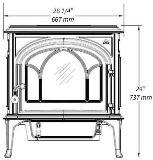
Fig. 1.2

1.1 Assembly Before Installation
The Jøtul F 445 is shipped with the flue collar attached in the top position and the front ash lip and combustor monitor (thermometer) inside the stove.
- Changing the Flue Collar to Rear Exit: While holding the M6 flange nuts on the inside of the flue collar to keep them from falling into the stove, use a 10 mm open end wrench or socket wrench to remove the two M6 bolts with M6 fender washers. Orient the flue collar to the rear and use the same hardware to re-attach it to the stove.
• Take out the front ash lip, which is inside the burn chamber. The ash lip is placed loosely on the base plate.
• See section 5.6 for combustor monitor installation. - INSTALL ACCESSORIES BEFORE LOCATING THE STOVE IN THE FINAL POSITION. Use the instructions provided with those kits.
Fig. 1.3 Rear exit center line hight.

Note: Use of the Short Leg Kit reduces the height of the rear exit by 2 1/4".
2. Chimney and Chimney Connector Requirements
2.1 Chimney Connector
The chimney connector is a single walled pipe used to connect the stove to the chimney. For use with the Jøtul F 445, the chimney connector must be 6" (152mm) in diameter, with a minimum thickness of 24 gauge black steel. Attach the flue collar to the chimney connection using 2 self-drilling screws found in the miscellaneous kit.
- Aluminum and Galvanized steel pipe is not acceptable for use with the Jøtul F 445. These materials cannot withstand the extreme temperatures of a wood fire and can give off toxic fumes when heated.
- Do not use the connector pipe as a chimney.
- Each chimney connector or stove pipe section must be installed to the stove flue collar and to each other with the male (crimped) end toward the stove. See figure 2.1. This prevents any amount of condensed or liquid creosote from running down the outside of the pipe or the stove top.
- All joints must be secured with three sheet metal screws.
- For the best performance the chimney connector should be as short and direct as possible, with no more than two 90^ elbows.
- The maximum horizontal run is 36" (915mm) and a recommended total length of stove pipe should not exceed 10 feet.
- Horizontal runs must slope upward 1/4" (6,35mm) per foot toward the chimney.
- Where passage through a wall or partition of combustible construction is desired, the installation must conform with NFPA 211 and is also addressed in this manual.
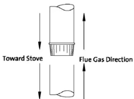
Fig. 2.1. Chimney connector assembly.
- No part of the chimney connector may pass through an attic or roof space, closet or other concealed space, or through a floor or ceiling.
- All sections of the chimney connectors must be accessible for cleaning.
- Where passage through a wall or partition of combustible construction is desired, the installation must conform with NFPA 211 and is also addressed in this manual.
- Do not connect this unit to a chimney flue servicing another appliance.
2.2 General Chimney Requirements
Canada Only: This fireplace insert must be installed with a continuous chimney liner of 6" diameter extending from the fireplace insert to the top of the chimney. The chimney liner must conform to the Class 3 requirements of CAN/ULC-S635, Standard for Lining Systems for Existing Masonry or Factory-Built Chimneys and Vents, or to the requirements of CAN/ULC-S640, Standard for Lining Systems for New Masonry Chimneys.
The F 445 is approved for use with:
- A code-approved masonry chimney and flue liner.
- A prefabricated chimney complying with the requirements for Type HT (2100°F) chimneys per UL 103.
An existing chimney system must pass a UL 1482 Level II inspection conducted by a qualified technician or building official.
The chimney flue size should not be less than the cross-sectional area of the stove flue collar, and not more than three times greater than the cross-sectional area of the flue collar.
NOTE: Consult your local code authority to determine what building and fire codes apply in your area before installing your new stove. Your local inspector has final authority in approving your installation.
Chimney Considerations
When choosing a chimney type and location in the house, keep this in mind: it is the chimney that makes the stove work, not the stove that makes the chimney work. The chimney allows the temperature difference between inside and outside air to create suction, called “draft”, which pulls air through the stove necessary to support combustion. Since draft is the force which moves air from the stove up through the chimney, its strength is critical to proper stove function. Besides air pressure differential, draft strength is affected other factors including:
• chimney condition and height
• surrounding construction, other buildings
* nearby trees, local geography
• wind conditions and climate
Any of the preceding conditions can adversely affect performance. Weak or erratic draft can cause “back puffing”- a condition when smoke leaks into the room through the stove or chimney connector joints. Poor draft will also make it difficult to maintain a steady, controlled burn and lead to creosote accumulation in the chimney or combustor.
A short, masonry chimney on the exterior of a house will promote poor performance. This is because it will be difficult to initiate and maintain temperatures warm enough to sustain adequate draft. In extremely cold northern areas, it may be necessary to reline the chimney or extend its height to help improve performance.
Conversely, a tall, masonry chimney inside the house will warm more quickly and retain heat longer.
On the other hand, overly strong draft can also cause a different set of issues such as excessive temperatures and short burn times
Ideally, whether masonry or prefabricated, the chimney should be centrally located inside the house where it will be least affected by exterior conditions and the stove's radiant heat can be most evenly dispersed.
The following guidelines give the necessary chimney requirements based on the national code, ANSI-NFPA 211. However, many local codes differ from the national code to take into account climate, altitude, or other factors.
Any chimney construction that penetrates the air barrier of a wall or ceiling/roof to the outside must be sealed in accordance to local building codes.
2.3 Masonry Chimneys
A masonry chimney must conform to the following guidelines:
- The chimney flue size should not be less than the cross-sectional area of the stove flue collar.
- The cross-sectional area of the flue of a chimney with no walls exposed to the outside below the roofline shall not be more than three times the cross-sectional area of the stove flue collar.
- The cross-sectional area of a chimney flue having one or more walls exposed to the outside below the roofline shall not be more than two times the cross-sectional area of the stove flue collar.
- Larger chimney flues should be relined with a listed or code approved liner.
- The masonry chimney must have a fireclay liner or equivalent, with a minimum thickness of 5/8" (16mm) and must be installed with refractory mortar. There must be at least 1/4" (6,35mm) air space between the flue liner and chimney wall.
- The fireclay flue liner must have a nominal size of 8" X 8", and should not be larger than 8" X 12". If a round fireclay liner is to be used it must have a minimum inside diameter of 6" (157mm) and not larger than 8" (208mm) in diameter.
- If a chimney with larger dimensions is to be used, it should be relined with an appropriate liner that is code approved.
- The masonry wall of the chimney, if brick or modular block, must be a minimum of 4"(106mm) nominal thickness. A mountain or rubble stone wall must be at least 12" (310mm) thick.
- A newly-built chimney must conform to local codes and in their absence must recognize national regulations. When using an existing chimney, it must be inspected by a licensed professional chimney sweep, fire official, or code officer, to ensure that the chimney is in proper working order.
- No other appliance can be vented into the same flue.
- An airtight clean-out door should be located at the base of the chimney.
This stove shall not be installed in a factory-built fireplace.
2.4 Prefabricated Chimneys
A prefabricated metal chimney must be tested and listed for use with solid fuel burning appliances to High Temperature (HT) Chimney Standard UL 103 for the U.S and ULC S629 in Canada.
The manufacturer's installation instructions must be followed precisely. Always maintain the proper clearance to combustibles as established by the pipe manufacturer. This clearance is usually a minimum of 2" (56mm), although it may vary by manufacturer or for certain chimney components.
2.5 Chimney Height
The minimum chimney height is 15 feet (4.57 m). The chimney must also be at least 3 feet higher than the highest point where it passes through the roof and at least 2 feet higher than the highest part of the roof or structure that is within 10 feet of the chimney, measured horizontally. See figure 2.2.
Chimneys shorter than 14 feet may not provide adequate draft. This could result in smoke spilling into the room from the stove when loading the stove, or when the door is open. In addition, inadequate draft can cause back puffing, which is a build up of gases inside the firebox.
Other times, chimney height can create excessive draft which can cause high stove temperatures and short burn times. Excessive drafts can be corrected by installing a butterfly damper. If you suspect you have a draft problem, consult your dealer.
Fig. 2.2. Chimney height; 3/2/10 Rule.

2.6 Wall Pass-throughs
When your installation unavoidably requires the chimney connector to pass through a combustible wall to reach the chimney, always consult your local building officials, and be sure any materials to be used have been tested and listed for wall pass-throughs.
In the U.S:
The National Fire Protection Association's publication, NFPA 211, Standard for Chimneys, Fireplaces, Vents and Solid Fuel Burning Appliances permits four methods for passing through a combustible wall. Before proceeding with any method be sure to consult with your local building officials to discuss any local code requirements.
Common Method:
- When passing through a combustible wall to a masonry chimney this method requires the removal of all combustible materials from at least 12" (310mm) around the chimney connectors proposed location. With a 6" (157mm)round liner the minimum area required would be 31" x 31" (792x792mm) square.
- The space is then filled with at least 12" (310mm) of brick around a fireclay liner. Remember, the liner must be ASTM C35 or equivalent, with a minimum wall thickness of 5/8" (16mm).
- It is important to remember to locate the pass-through at least 18"(457mm) from the ceiling for proper clearance to combustibles.
- It will be necessary to cut wall studs, install headers, and construct a sill frame to maintain the proper dimensions and to support the weight of the brick.
- The bricks must be solid brick with a minimum of 3 1/4 “ (83mm) thick 4” (106mm) nominal).
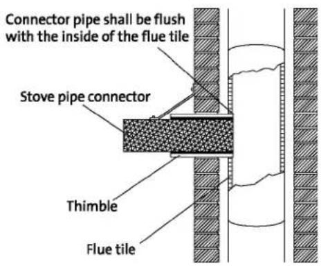
- Refractory mortar must be used at the junction of the chimney and the pass-through liner. The pass-through liner must not penetrate the chimney liner beyond the inner surface of the chimney liner. Use extreme care when constructing the hole in the chimney liner, the tiles can shatter easily. See figure 2.3.
Consult your local building inspector and authorized Jøtul Dealer for other approved wall pass-through methods.
3. Connecting to the Chimney
3.1 Masonry Chimney Thimble
In Canada:
The installation must conform to CAN/CSA-B365, Installation Code for Solid Fuel Burning Appliances and Equipment. Before proceeding be sure to consult your local building inspector. Common Method:
This method requires the removal of all combustible materials from at least 18" around the chimney connector's proposed location. A 6" round liner requires a minimum opening 43" x 43" square. Locate the pass-through at least 18" from combustible ceiling materials.
The space that is cleared of combustible materials must remain empty. Sheet metal panels can be used to cover the area. However, when using a panel on both sides of the wall, each cover must be installed on noncombustible spacers at least 1" from the wall. If one panel of sheet metal is to be used it may be installed flush to the wall. See section 5.3.1 and 5.3.2 of CSA - B365. Consult your local building inspector, authorized Jøtul Dealer, NFPA 211 in the U.S. or CSA-B635 in Canada for other approved wall pass-through methods.
When connecting the stove to a masonry chimney through a "thimble" (the opening through the chimney wall to the flue), the thimble must be lined with ceramic tile or metal and be securely cemented in place. See fig. 2.3.
- The chimney connector/stove pipe must slide completely inside the thimble to the inner surface or the flue liner. A slip-connector may be used to permit adjustability and ease maintenance / cleaning access. See fig. 3.1.
- The connector pipe or thimble sleeve must not protrude into the flue liner where it could restrict the free flow of exhaust gas and cause poor stove performance.
- The chimney connector should be sealed at the thimble with refractory cement and each connector joint must be secured with three sheet metal screws.
- Do not connect this stove to a chimney flue servicing another appliance of any kind.

Fig. 2.3. Masonry chimney penetration.
Fig.3.1. Chimney thimble components.
DO NOT INSTALL IN ANY FACTORY BUILT FIREPLACE.
3.2 Hearthmount Into a Masonry Fireplace
Consult your local building inspector for codes on fireplace installation. The Jøtul F 445 has a rear exit flue collar height of 28 1/4" (718 mm) when installed with standard legs. Substitution of Short Legs will lower the height by
2 1/4" to 26" (660 mm).
- The NFPA 211 standard (12.4.5.1) requires that a masonry flue serving a wood-burning appliance must be sealed off from room air. This can be accomplished by two methods:
1) Replace the fireplace damper with a fixed steel plate through which the connector pipe must extend from the stove to the chimney flue tile. See figure 3.2. Alternatively, the flue may be sealed off by installing a non-combustible plate at the fireplace opening. In either case, the block-off plate and connector pass-through must be sealed using high-temperature or other appropriate sealant. Jøtul recommends a block-off plate installed in any fireplace damper area for improved heat efficiency.
2) Install a full, listed chimney liner from the stove to a direct connection at a sealed chimney cap. Your Jøtul dealer can recommend an approved system.
• See Section 2.3 on page 7 for cross-sectional flue size requirements related to interior vs exterior chimneys.
- If the chimney liner is too large to accommodate the stove, a code-approved relining system must be installed to resize the flue.
- The fireplace installation must also conform to the tested clearances to surrounding trim and mantels. See clearance specifications on pages 14-15. In addition, a fireplace installation must also comply with the floor protection guidelines specified on page 11.
3.3 Prefabricated Chimneys
The Jøtul F 445 may be connected to a prefabricated metal chimney following the pipe manufacture's instructions.
Use all required components. Most manufacturers offer an adaptor that attaches to the bottom section of the metal chimney and permits the connector pipe to be secured to it using three sheet metal screws. See figure 3.3.
Fig. 3.3. Prefabricated chimney components.

Fig. 3.2. Fireplace chimney construction.
* Max Depth is 10" measured from the front of the front leg.

4. Clearances to Combustibles
4.1 Floor Protection Requirements
The F 445 requires a listed UL 1618 floor protection as specified below in any installation unless installed on concrete over earth.
* The supplied bottom heat shield must be installed on the stove.
• Floor protection under the stove must be composed of continuous, non-combustible materials for protection against sparks and embers.
* Individual sections of floor protection must be mortared or otherwise sealed together to prevent spark penetration to combustible floor materials. Any carpeting must be removed from under the floor protection.
- Alcove Installations: In addition to the Bottom Heat Shield, floor protection must include materials having a minimum R-value of 1.6. See section 4.2, to determine various material R-values.
In the U.S.:
The hearth protection surface must extend continuously in front of the stove:
• A minimum of 16".
- A minimum of 6" on each side (measured from the opening of the front door).
This will result in a minimum floor protection of
33"W X 40"D. See figure 4.1.
Fig. 4.1. F 445 Hearth Dimensions USA.

In Canada:
The hearth protection surface must extend continuously in front of the stove:
• A minimum of 18" (457mm)
- A minimum of 8" (200mm) on the side and back of the stove (measured from side and back panels).
This will result in a minimum floor protection of 41"W X 48"D (1041mm x 1219mm). See figure 4.2.
Fig. 4.2. F 445 Hearth Dimensions Canada.
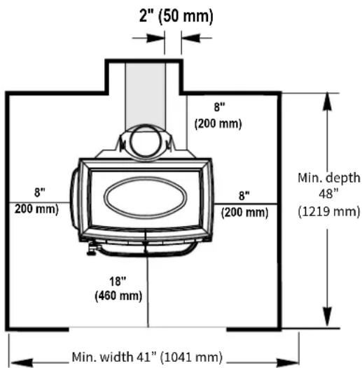
For a rear vent installation, the floor protection must also extend under the stove pipe a minimum of 2" (50mm) beyond either side of the pipe in both the U.S. and Canada. Figs. 4.1 and 4.2.
4.2 Alternate Floor Protection
All floor protection materials must be non-combustible ie. metal, brick, stone, mineral fiber boards). Any combustible material may not be used.
The easiest means of determining if a proposed alternate floor material meets requirements listed in this manual is to follow this procedure.
R-value = thermal resistance
k-value = thermal conductivity
C-value = thermal conductance
- Convert the specification to R-value;
a. If R-value is given, no conversion is needed.
b. If k-value is given with a required thickness (T) in inches: R=1/k×T.
c. If C-value is given: R=1/C.
- Determine the R-value of the proposed alternate floor protector.
a. Use the formula in Step 1 to convert values not expressed as "R".
b. For multiple layers, add R-values of each layer to determine overall R-value.
3. If the overall R-value of the system is greater than the R-value of the specified floor protector, the alternate is acceptable.
Example:
The specified floor protector should be 3/4" thick material with a k-factor of 0.84. The proposed alternate is 4" brick with a C-factor of 1.25 over 1/8" mineral board with a k-factor of 0.29.
Step A. Use formula above to convert specifications
to R-value. R=1/k X T=1/.84 X .75=.893
Step B. Calculate R of proposed system.
4" brick of C-1.25, therefore
R brick = 1/C = 1/1.25 = 0.80.
1/8" mineral board of k = 0.29 therefore
R mineral board = 1/.29 × 0.125 = 0.431
Total R = R brick + R mineral board=
0.8 + 0.431 = 1.231
Step C. Compare proposed system R = 1.231 to specified R of 0.893.
Since R is greater than required, the system is acceptable.
Definitions:
Thermal conductance =
$$ C = \quad \underline {{B t u}} \quad = \quad \underline {{W}} $$
$$ (h r) (f t ^ {2}) (F) \quad (m ^ {2}) (K) $$
Thermal conductivity =
$$ k = \underline {{\text { Btu }}} _ {(h r) (f t ^ {2}) (F)} = \underline {{\text { W }}} _ {(m ^ {2}) (K)} = \underline {{\text {(Btu)}}} _ {(h r) (f t) (F)} $$
Thermal resistance =
$$ R = \underline {{B t u}} = (\underline {{m ^ {2}}} (K) = (\underline {{B t u}}) (\text { inch }) $$
$$ (h r) (f t ^ {2}) (F) \quad W \quad (h r) (f t ^ {2}) (F) $$
Alcoves require use of a bottom heat shield and hearth protection having a minimum R-value of 1.6.
Note about Luxury Vinyl Flooring: Vinyl flooring and similar materials may be damaged if F 500 V3 is installed within 57" of the front of the stove. We recommend NO luxury vinyl
flooring within that space.
4.3 Clearances to Walls and Ceilings
The following clearances have been tested to UL and ULC standards and are the minimum clearances specifically established for the F 445.
The following diagrams give the required clearances you must maintain when installing the F 445 near combustible surfaces. See pages 14-15.
A combustible surface is anything that can burn (i.e. sheet rock, wall paper, wood, fabrics etc.). These surfaces are not limited to those that are visible and also include materials that are behind non-combustible materials.
If you are not sure of the combustible nature of a material, consult your local fire officials. Contact your local building officials about restrictions and installation requirements in your area.
"Fire Resistant" materials are considered combustible; they are difficult to ignite, but will burn. "Fire-rated" sheet rock is also considered combustible.
Ventilation and air circulation within the clearance space must be maintained. DO NOT BLOCK OFF AIRFLOW AROUND THE CLEARANCE SPACE!
4.4 Using Shields to Reduce Clearances
Pipe shields: When using listed pipe shields to reduce the connector clearance to combustibles, it must start 1"(25,4mm) above the lowest exposed point of the connect pipe and extend vertically a minimum of 25" (635mm) above the top surface of the stove.
Double wall pipe: Listed double wall pipe is an acceptable alternative to connector pipe heatshields.
Wall-Mounted Protection: When reducing clearances through the use of wall mounted protection:
Refer to NFPA 211, Standard for Chimneys, Fireplaces, Vents and Solid Fuel Burning Appliances, for acceptable materials, proper sizing and construction guidelines.
Jøtul F 445 Rear Heatshield Kit #158374
This shield is specifically approved for use to reduce clearances on this appliance only. No other heat shield may be used.
See pages 14-15 for complete clearance specifications and diagrams.
NOTE: Accessories approved for clearance reduction have been developed by many manufacturers. Be sure that any accessory you choose has been tested and listed by an independent laboratory and carries the laboratory's testing mark. Follow all of the manufacturer's instructions.
Always contact your local building inspector or fire officials about restriction and requirements in your area. Your local officials have final authority for installation approval.
4.5 Alcove Installation
This appliance may be installed in an alcove provided: (See figures 4.4 and 4.5.)
- The stove must be installed with listed, double-wall pipe.
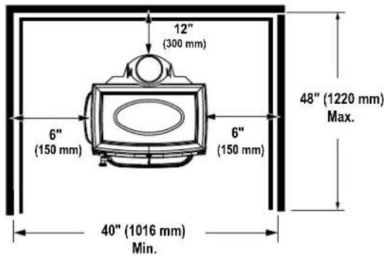
- In a protected alcove installation both side walls and rear wall must be protected per NFPA 211. The wall protection must be elevated 1" (24,5mm) from the floor and at least 1" (24,5mm) off the combustible wall to allow for cooling air-flow.
- The height of the wall protection including the bottom air space must be 48"(1219mm).
- Clearance specifications are designated between the stove plates and the combustible wall surface.
- The bottom heatshield is required in all Alcove installations. See figure 4.3, for installation instructions.
- Hearth protection material must consist of: a) a UL/ULC listed Type II Thermal Floor Protector or, b) material having a minimum r value of 1.6 (see section 4.2).
- Minimum ceiling height in an unprotected installation, off the top of the stove is 41"(1041 mm). The minimum ceiling height off the top of the stove in a protected ceiling installation is 15"(380mm).
Fig. 4.3. Bottom heat shield installation.

1) Bend the flattened heat shield on the perforations as shown, painted side down.
2) Use a 10 mm wrench to remove the two bolts from the bottom of the ash compartment.

natural_image
Two identical gray outdoor furniture or sinkware units with curved surfaces and legs, connected by a diagonal line (no text or symbols visible)3) Oriented as shown, use the two bolts to attach the heat shield to the stove bottom.
Fig. 4.4. Alcove unprotected wall clearances.

Fig. 4.5. Alcove protected wall clearances are designated between the stove surfaces and the combustible wall surface.
Jøtul F 445 Clearances
These clearance specifications result from safety testing by Intertek Testing Services, Inc. Use the table below together with the diagrams on the facing page to determine the clearances for your particular installation.
- Stove clearances result from tests that include the chimney connection in the system.
- Chimney connector clearances listed separately are from NFPA 211, independent of the stove position.
| Stove Clearance | Unprotected surface | Protected surface* | ||||
| Side | Rear | Corner | Side | Rear | Corner | |
| Stove - no heat shield | 14” A | 16” B | 13” C | 6” D | 12” E | 9” F |
| Single-wall pipe | 356mm | 406mm | 330mm | 152mm | 305mm | 230mm |
| Stove with rear heat shields and single-wall pipe | 14” A | 10” G | 9” F | 6” D | 10” G | 9” F |
| 356mm | 255mm | 230mm | 152mm | 255mm | 230mm | |
| Stove with rear heat shield and connector shields or double-wall pipe | 14” A | 6” D | 9” F | 6” D | 6” D | 6” D |
| 356mm | 152mm | 230mm | 152mm | 152mm | 152mm | |
Horizontal Connector Clearance (X)
| Unprotected surface | Protected surface* | ||
| Single-wall pipe | 18” | 457mm | 12” 300mm |
| Double-wall pipe | 6” | 152mm | 6” 152mm |
Fireplace Mantle and Trim Clearance
| Stove Side to Side Trim - 1" thick or less: | 12" | 305mm |
| Stove Top to Upper Trim - 1" thick or less: | 16" | 406mm |
| Stove Top to Mantle - 12" maximum depth: | 30" | 762mm |

natural_image
Pure technical line drawing of a mechanical assembly without any text, numbers, or symbolsMantel and Trim clearances may be reduced by 50% following protection construction methods specified by NFPA 211 Standards for Chimneys, Fireplaces, Vent and Solid Fuel Burning Appliances or similar local regulations.
UNPROTECTED WALLS
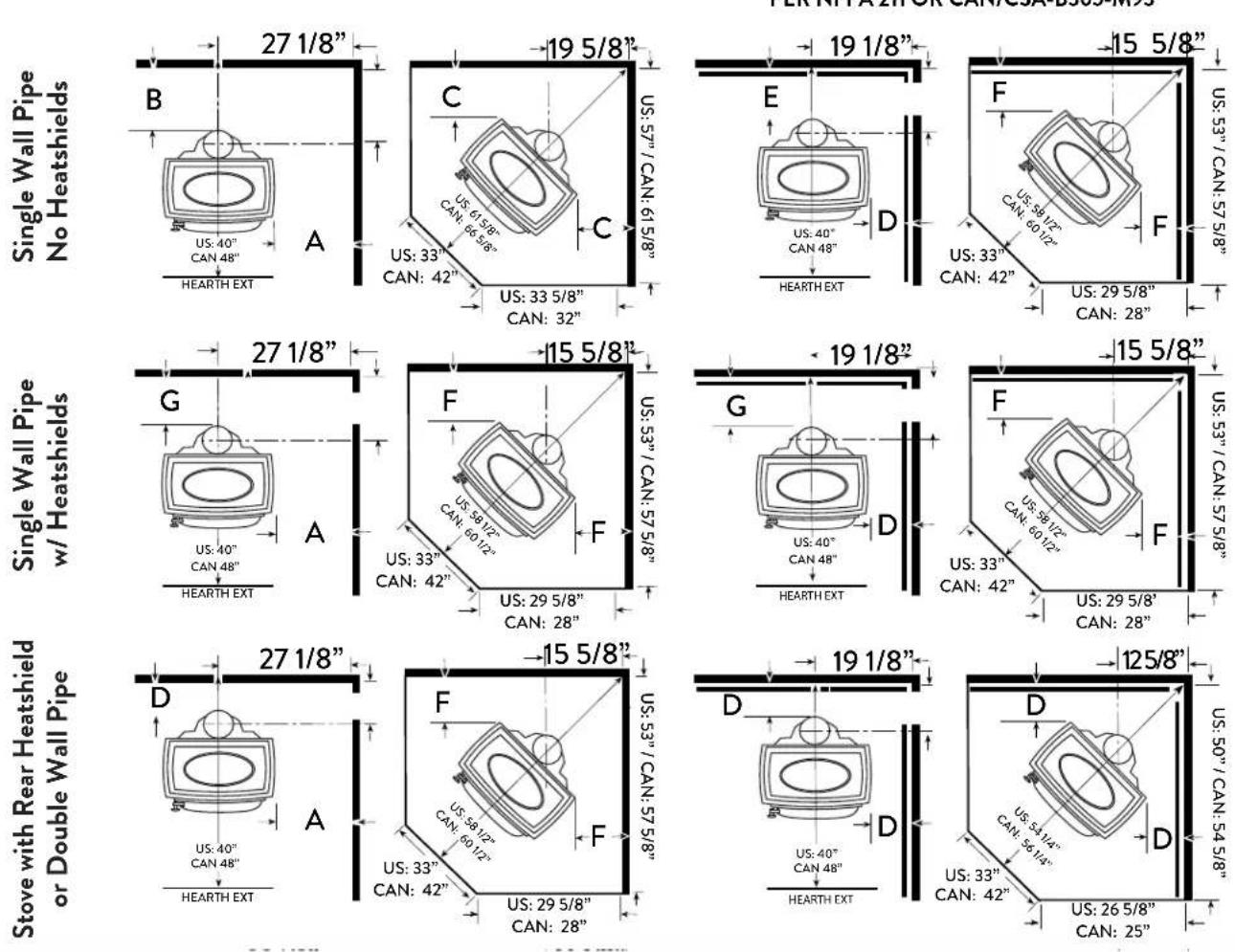
PROTECTED WALLS
PER NFPA 211 OR CAN/CSA-B365-M93
Important:
Connector heatshields and double wall pipe must be a listed product.
Always follow the manufacturer's instructions.
4.6 Mobile Home Installations
The F 445 has been approved for use in mobile homes in the U.S. and Canada provided:
- The stove is physically secured to the floor or the mobile home. Use Jotul Floor Mounting Kit #750304.
CAUTION: The structural integrity of the mobile home, floor wall and ceiling/roof must be maintained.
- All chimney components, including chimney sections, supports, spark arrestor, etc., shall comply with the Standard for Factory-built Chimneys for Residential Type and Building Heating Appliances, UL 103 Standard for 650°C Factory-built Chimneys.
- The chimney shall be attached directly to the stove and extend at least 3 ft. (0.9m) above the roof. Termination must be at least 2 ft. (0.6m) above the highest elevation of any part of the mobile home within 10 ft. (3m).
- In order to allow for transportation of the mobile home, the chimney termination shall be readily removed at or below an elevation of 13.5 ft. (4.1 m) above ground level and reinstalled without use of special tools or instructions.
- A spark arrester must be installed at the termination. The net free area of the arrester above the chimney outlet must not be less than four times the net area of the chimney outlet, and the vertical height of the arrester must not be less than one-half the diameter of the chimney flue. Openings shall not permit the passage of a sphere having a diameter larger than 1/2" (12.7 mm), and shall permit the passage of a sphere having a diameter of 3/8" (9.6 mm).
- Direct connection of the stove to an outside air source is required. Use Outside Air Kit #154335. Do not substitute any other connection method or device. See page 15 for more details. Duct termination must not be installed at a level that is higher than the air inlet located at the bottom of the stove.
- When the chimney exits the mobile home at a location other than through the roof, and exits at a point 7 ft. (2.1 m) or less above the ground level, a guard or other method of enclosing the chimney, must be provided at the point of exit for a height up to 7 ft. Openings of this chimney guard shall not permit penetration of a 3/4 in. (19.1 mm) diameter rod, or contact with the chimney by a 1/2 inch (12.7 mm) diameter rod inserted through the opening a distance of 4 inches (102 mm).
WARNING: DO NOT INSTALL THE STOVE IN A BEDROOM OR SLEEPING AREA.
Always consult your local building inspector or fire officials to determine other mobile home restrictions and requirements in your area prior to installing the stove.
Remove the chimney for transportation of the building.
5. Operation
Please read the following section completely before building a fire in your new Jøtul F 445.
DO NOT OVERFIRE THIS HEATER. THE MAXIMUM RECOMMENDED OPERATING TEMPERATURE OF THE COMBUSTOR IS 1600°F (870°C). DAMAGE CAN OCCUR TO THE COMBUSTOR IF IT EXCEEDS 1750°F (954°C) FOR EVEN BRIEF PERIODS OF TIME.
5.1 Combustion Efficiency
The Jøtul F 445 has an EPA test High Heating Value (HHV) efficiency rate of 72%. There are, however, aspects of efficiency that you should be aware of in order to get the most from your stove. Operation habits and fuel moisture can have a significant effect on efficiency. Poorly seasoned wood having a higher than optimum moisture content, can reduce the amount of energy transferred to the living area as a result of the energy expended to evaporate the excess fuel moisture in order for the wood to burn. Operational habits - such as not building a robust kindling fire to readily ignite the larger fuel pieces - can result in an inefficient, smoldering fire. Additionally, most modern wood heaters' optimum performance and efficiency are at the medium to medium-low burn rates.
The location of the stove can also have a significant effect on heating efficiency, primarily in regard to distribution of the heat. For example, a wood heater centrally located in an open living area, will likely provide better circulation of heat than will a stove located in a room adjacent to the larger living area.
WARNING: OPERATE THIS APPLIANCE ONLY WITH THE DOOR FULLY CLOSED. OPERATION WITH THE DOOR LEFT PARTIALLY OPEN MAY CAUSE OVERFIRING. Also, if doors are left partially open, combustion gas and flame may be drawn out of the stove, creating risks from both fire and smoke.
WARNING: Door glass is fragile. Take care to not strike the glass or slam the door during operation.
5.2 Minimize Carbon Monoxide Emissions
Testing the F 445 to CSA B415.1-10 resulted in a carbon monoxide emission rate of .60 grams per minute. There are properties related to CO generation that you should be aware of. Most means of combustion produce CO, including wood fire. You can greatly reduce CO levels by maintaining a well-established fire and avoiding operation that produces a smouldering, smoky fire. We highly recommend that a CO monitor (detector) be installed in the same room as the stove. The monitor should be located as far away as possible from the stove to avoid alerts when the doors are opened.
5.3 Wood Fuel and Performance
Use dry wood.
The F 445 is designed to burn natural wood only. Higher efficiencies and lower emissions generally result when burning air-dried, seasoned hardwoods, as opposed to softwoods, green or freshly cut hardwoods. Wood that has been air-dried for a period of 6 to 14 months will provide the cleanest, most efficient heat. Wood seasoned more than 2 years will burn too quickly to take advantage of the stove's low end efficiency strength.
A seasoned log will have many check marks (cracks) through the ends and be lighter than an unseasoned log which will show few or no check marks.
We recommend using a moisture meter that incorporates probes to determine the moisture content of your wood. Meters are available at your dealer or local hardware store. For purposes of home heating, your fuel should have a moisture content between 12 - 20% on the meter gauge. Wood with higher moisture content will burn, however, very inefficiently. Most of its heat value will be lost through evaporation, driving water out of the wood. Worse, that moisture will condense as creosote in the relatively cool chimney flue, increasing the potential for a chimney fire and weak draft strength. Use of unseasoned wood defeats the purpose of any modern wood-burning stove. Store your wood in a dry location outside of the combustible clearance area stated previously in this manual.
BURN UNTREATED WOOD ONLY. DO NOT BURN:
- Coal;
- Garbage;
- Synthetic fuel or logs;
- Material containing rubber, including tires;
• Material containing plastics; - Waste petroleum products, asphalt products, paints, paint thinners or solvents;
- Materials containing asbestos;
- Construction or demolition debris;
- Railroad ties or pressure-treated wood;
- Manure or animal remains;
- Lawn clippings or yard waste;
- Salt water driftwood or other previously salt-water; saturated materials;
- Unseasoned wood;
- Colored paper, or
- Paper products, junk mail, cardboard, plywood, or particle board. (The prohibition against burning these materials does not include the use of fire starters made from paper, cardboard, saw dust, wax or similar substances for the purpose of starting a fire.)
- Burning of any of the materials listed above can result in the release of toxic fumes including carbon monoxide, cause smoke, or render the heater ineffective. Carbon monoxide poisoning can cause headache, dizziness, loss of consciousness and death.
- IT IS AGAINST FEDERAL REGULATIONS TO OPERATE THIS WOOD HEATER IF THE CATALYTIC ELEMENT IS DEACTIVATED OR REMOVED.
- NEVER USE GASOLINE, GASOLINE-TYPE LANTERN FUEL, KEROSENE, CHARCOAL LIGHTER FLUID OR SIMILAR LIQUIDS TO START OR "FRESHEN-UP" THE FIRE. ALWAYS KEEP SUCH LIQUIDS AWAY FROM THE HEATER AT ALL TIMES.
- NOTE: Prevent logs from resting directly on the glass panel. Logs should be spaced off of the glass enough to promote unrestricted air flow within the firebox.
WARNING: Do not operate with broken glass.
WARNING: DO NOT OVER-FIRE THIS HEATER. IF ANY PART OF THE STOVE OR CHIMNEY CONNECTOR GLOWS, WITH THE EXCEPTION OF THE COMBUSTOR, YOU ARE OVER-FIRING. A HOUSE FIRE OR SERIOUS DAMAGE TO THE STOVE OR CHIMNEY COULD RESULT. ATTEMPTS TO ACHIEVE HEAT OUTPUT RATES THAT EXCEED HEATER DESIGN SPECIFICATIONS CAN RESULT IN PERMANENT DAMAGE AND VOID YOUR WARRANTY ON THE STOVE AND ITS COMPONENTS.
5.4 F 445 Control Functions
The F 445 is designed to support efficient combustion and optimal heat transfer by directing air to the fire through two separate channels; Primary and Secondary. See figure 5.1.
Primary Air is manually regulated by a lever-controlled valve located at the front center of the stove, directly below the door. See fig. 5.2. The lever position controls the volume of primary air entering the firebox and thereby affects fire intensity, heat output and burn time. Primary air is directed to the main body of the fire through air ports at the front of the stove. Separate manifolds at each side also deliver pre-heated primary air above the front doors and create an 'air-wash" to help keep the viewing glass clean.
Secondary air is automatically regulated to promote combustion of volatile gas that would otherwise be exhausted to the atmosphere unburned. The secondary air inlet is located at the back of the stove where a temperature-sensitive bimetal coil continuously varies the volume of air introduced to fire. This air is preheated as it passes over the back and top of the firebox, directed to the secondary combustion baffle and delivered to the catalytic combustor.
Fig. 5.2. Primary air lever settings
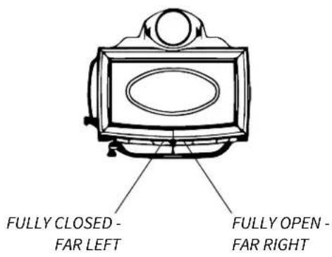
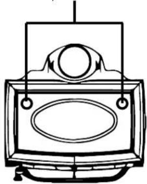
Fig. 5.3. Stove-top Thermometer locations
natural_image
Line drawing of a vintage television set with an antenna and ovals (no text or symbols)Fig. 5.1. F445 Combustion air flow.

The combustor maintains the high temperatures necessary to burn volatile gas that would otherwise pass unburned into the atmosphere. When the combustor is functioning, no smoke will be observed exiting the chimney. This is evidence that the stove is operating in the so-called "sweet-spot" wherein optimum efficiency is realized.
Secondary air is always available to the secondary combustion baffle and the catalytic combustor. The automatic control valve functions to provide the appropriate amount of secondary air relative to maintaining optimal clean combustion.
When first starting or reviving the fire: the primary control lever should be set to the far right position, which permits the maximum amount of air into the stove. The greater the amount of air entering the stove, the hotter and faster the fire will burn.
Moving the lever to the left reduces the airflow into the stove and thereby prolonging the fire at a lower heat output. See figure 5.2.
Control Settings and Performance
Use the table below as a guide to achieve the best performance from your stove.
Burn Rate Air Control Setting Blower Speed
Low Fully to the Left Minimum Med. Low 3/16" to the Right Minimum Med. High 3/8" to the Right Medium High Fully to the Right High
The valve lever should be set at Full Open (Right) for the first five minutes of the Low, Medium Low and Medium High burn rate.
5.5 Use of a Stove-top Thermometer
Determining the primary air setting for the best overall performance for your particular needs and installation will be established over time and experience. Each installation has unique characteristics that affect stove performance. You should use a stove-top thermometer to monitor the status of the fire. Place the thermometer on the stove top, in either rear corner. See figure 5.3. Generally speaking, once the stove temperature has reached 400^ F - 600^ F ( 204^ C - 316^ C), the air control may be set in a mid-range position to allow adequate oxygen to support efficient combustion throughout the burn cycle. Temperatures of 700-800 for short periods of time will not harm the stove, but prolonged periods of time in that temperature range can damage the stove. Use of the stove top thermometer is the best way to monitor how your stove is performing.
5.6 Using the Combustor Monitor
Each installation has unique physical and environmental characteristics that will affect stove performance. Other variables affecting combustion efficiency are cordwood species and moisture content. Taking those variables into consideration, you should use the integrated Combustor Monitor to maintain the fire in the most efficient manner tailored to your specific needs and installation configuration.
You can readily monitor combustion efficiency by noting the temperature indicated on the Combustor Monitor shown in figure 5.4. Follow this procedure to install the Combustor Monitor:
- Remove the lower set screw on the right side panel of stove using a 3mm hex key as shown in figure. 5.5. DO NOT REMOVE THE UPPER SET SCREW. It secures the top plate to the sides.
Fig. 5.4. Combustor Monitor, PN 226609

Fig. 5.5.
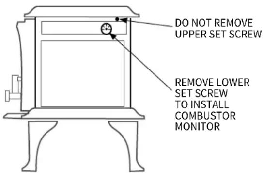
Fig. 5.6. Remove magnet from current orientation
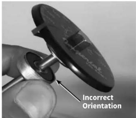
Fig. 5.7. Orient magnet

Fig. 5.8. Final position of magnet
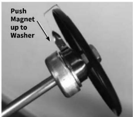
- Take the magnet off of Combustor Monitor and replace it in the correct orientation as shown in figures 5.6-5.8.
- Insert the Combustor Monitor fully into the hole with the magnet attaching to the cast iron side plate as shown in figure 5.5.
Seated within the right side directly behind the catalytic element, the Combustor Monitor accurately responds to combustion activity. Secondary combustion takes place at temperatures between 500°F (260°C) and 1200°F (260°C - 649°C).
The primary air valve should remain at the fully open setting, (to the Right), at least until the monitor registers 500^ F ( 260^ C). Maintain that temperature for 15-20 minutes before adjusting the primary air lever to Medium Low-Medium High settings. The optimum temperature range for most efficient combustion is between 500^ F and 800^ ( 260^ C -371°C). Chimney draft should be in the .05 - 1.0 w.c. range. The so-called “sweet spot” combustion zone is best maintained at those temperatures. However it is not uncommon for combustion temperatures to reach over 1,400^ F ( 760^ C).
Visual Monitoring
Evidence of efficient combustion can be observed in three distinct ways:
- At temperatures over 500^ F, look up through the door glass to the steel baffle and catalytic element at the top of the firebox. As exhaust gases ignite, jets of flame can be seen projecting from the baffle ports and the catalyst will glow vividly red.
- Little or no smoke will be seen flowing from the chimney flue outside of the house.
- If the stove has been properly operated, brushing the chimney flue will produce mostly fly ash. Little or no creosote accumulation will be evident.
5.7 Stove Break-In Procedure
The Jøtul F 445 is constructed of cast iron plates and sealed with stove furnace cement. Cast iron, while very durable, expands and contracts as it is heated and cooled. This type of construction requires the stove to be “broken-in” gradually so that thermal expansion does not occur too quickly. This process is accomplished by burning a short series of small-to-medium fires as described below.
-
Fully open the primary air valve. Light a small fire of newspaper and kindling. Only allow the stovetop thermometer to reach a surface temperature of 200^ F ( 93^ C). Maintain the fire at that level for approximately 1 hour and allow the stove to cool to room temperature.
-
Light a second fire, allowing the stove to reach a maximum surface temperature of 400^ F ( 204^ C) for 1 hour.
- Cool the stove to room temperature.
- Light a third fire and gradually allow the stove to reach and maintain a surface temperature of 500^ F ( 260^ C).
- Cool stove to room temperature. This completes the "break-in" procedure.
NOTE: Keep the stove under 400^ F ( 204^ C) surface temperature during any “break-in fire”, with the exception of the last “break-in” fire. If the temperature exceeds 400^ F, move the primary air control lever all the way to the left to minimize the air supply. It is normal for the stove top temperature will continue to climb until the fuel burns down somewhat. Once the fire is out and the stove has cooled to room temperature, continue the break-in procedure. Never attempt to reduce the temperature by removing burning logs from the fire.
5.8 Starting and Maintaining a Fire
Burn only solid wood directly on the bottom grate of the stove. Do not elevate the fire in any way.
WARNING: THE ASH PAN DOOR MUST ALWAYS BE SECURELY CLOSED WHEN THE STOVE IS BURNING. OPERATING THE STOVE WITH THE ASH DOOR OPEN WILL PROMOTE UNEVEN THERMAL EXPANSION AND CAN RESULT IN DAMAGE TO THE STOVE AND VOID YOUR WARRANTY.
Traditional Fire Building
- Set the primary air control lever in the full open position (to the right). Place several sheets of crumpled newspaper placed directly on the grate. On top of the newspaper, place several pieces of small dry kindling (approx. 1" in diameter) with two to three small logs (approx. 3" to 5" in diameter) on top.
- Light the fire and close the door, slowly building the fire by adding larger and larger logs. Be sure to follow the break-in procedure before creating a hot fire that could damage the stove.
- Once the stovetop thermometer has reached a temperature range of between 500° and 600°, (260°C -316°C), adjust the primary air control lever as necessary to generate the heat output and burn time desired.
Top-Down Fire Building - See figure 5.9.
As an alternative to the traditional "teepee" fire starter, the Top-Down method minimizes start-up smoke and more quickly establishes strong draft through the chimney.
- With the primary air control lever in the full open position (to the right), place two short 1/4-split logs on the firebox floor, perpendicular to the rear wall, about 6 inches apart.
- Place kindling across the base logs.
- Place one or two smaller logs on top of the kindling.
- Place newspaper between the two bottom logs under the kindling. Light the news paper and close the door. Continue to add kindling and small logs as necessary to build the fire. Keep the air control fully open until the fire is well-established.

natural_image
Illustration of stacked wooden logs with geometric cutouts (no text or symbols)Fig.5.9. Top-down fire-starting log tier.
5.9 Creosote and Soot Formation and the Need for Removal
When wood is burned slowly or when burning green wood, it produces tar and other organic vapors which combine with expelled moisture to form creosote. These creosote vapors condense in the relatively cool chimney flue of a slow burning fire. The creosote that accumulates in the flue is highly flammable and is the fuel of chimney fires. To prevent a chimney fire, the creosote needs to be removed by sweeping the chimney and flue connector.
The frequency of sweeping will depend on how you operate your stove. An accumulation of 1/4" or more on the sides of the flue or connector is considered hazardous and should be removed.
In the event that creosote in your chimney or flue connector ignites, the resulting fire is often accompanied by a roaring noise and a crackling sound as flakes of burned creosote break loose. If you suspect you are having a chimney fire, immediately close the primary air control and make sure the stove door is closed. Call the fire department and get everyone safely out of the house.
Do not attempt to extinguish the fire in the stove. Doing so can make the matter worse by supplying additional oxygen, which will accelerate the fire in the chimney. When the roaring and crackling has subsided, resist the temptation to open the door to check the fire. The fire may have suffocated, but could rekindle when you open the door. After a chimney fire, do not use your stove until the chimney and the flue connector has been cleaned and inspected to ensure that no damage has occurred.
5.10 Adding Fuel
Reload the stove while a bed of hot embers still exists, Follow this procedure:
• Always wear gloves when tending to the stove.
- Push the air control lever to the full open position (far right).
- To minimize any smoke spillage, open the door slightly before opening fully. This will allow air flow to stabilize within the firebox and chimney flue.
- Use a stove tool or poker to distribute the hot embers equally around the firebox and away from the air inlet ports at the front center of the firebox floor.
- Load the fuel, usually with smaller logs first.
- Close the door and secure the latch tightly.
- Wait 5 – 10 minutes before adjusting the primary air to the desired heat output setting. (If there remains at least a 2" thick ember bed when reloading, it may be possible to close the door and immediately adjust the air control setting).
- DO NOT over-load the stove. Do not load the wood higher than the holes on the air baffle. For safety and best appearance, maintain a traditional three log configuration.
- Remember that when burning the stove with the screen in place, heat efficiency is sacrificed for aesthetics and wood will be consumed at a much faster rate.
6. Maintenance
Regular maintenance will prolong the life of your stove and ensure satisfactory performance.
Warning: Use only Jøtul authorized parts. Do NOT use substitute glass.
6.1 Annual Stove Inspection
- Empty stove of all soot and ashes. Only use a vacuum for this job if the vacuum is specifically designed to handle ashes.
- Inspect the stove seams. Use a utility light to inspect the stove inside and out for cracks or leaks. Replace all cracked parts and repair any cement leaks with furnace cement. Always wear safety gloves when handling the ash pan.
- Inspect the Catalytic Combustor. See section 6.7.
6.2 Ash removal
Ash removal will be required periodically depending on how frequently the stove is used. Conveniently, the Jøtul F 445 is equipped with an ash pan for easy ash removal without the need to open the front door.
The ash pan door is located under the front ashlip of the stove. To open the ash door, rotate the door handle counterclockwise to unlatch the door and clockwise to latch the door. Always use stove gloves when handling the ash pan. Always close the ash door before leaving to dispose of the ashes when the stove is burning.
Ashes should be placed in a metal container equipped with a tight sealing lid. The container should be placed on a noncombustible floor or on the ground, well away from all combustible materials, pending final disposal. If the ashes are disposed of by burial in soil or otherwise locally dispersed, they should be retained in the closed container until all cinders have thoroughly cooled. Only use a vacuum for this job if the vacuum is specifically designed for ashes.
It is advisable to always keep a one inch bed of ashes on the firebox floor to help maintain a charcoal bed and insulate the bottom.
6.3 Chimney System
The Jøtul F 445 is designed to burn cleanly and efficiently when used according to the guidelines in this manual. In order to maintain proper performance, you should inspect the chimney and chimney connector at the beginning of each heating season and then every other month during the heating season.
Clean the chimney whenever creosote and fly ash accumulation exceeds 1/4 inch in any part of the system. Chimney brushes are available from your local Jøtul dealer or hardware supply store. Your dealer can also refer you to a reputable, professional chimney sweep who will have all the equipment to ensure a complete and proper job. Failure to keep the chimney system free of creosote and build-up could result in a serious chimney fire.
6.4 Enamel Care
- DO NOT ATTEMPT TO CLEAN HOT ENAMEL SURFACES. Clean only cold enamel surfaces with a soft damp cloth and polish with a clean dry cloth. Most stains can be removed with a solution of baking soda and vinegar. Let this solution sit on the stain for a minute or two before rubbing it dry with a damp cloth. Organic cleaning commercial cleaning solutions, such as Citra-Solv®, can also be effective.
- DO NOT USE SOAPY OR ABRASIVE SOLUTIONS. These can cause stains. Coffee, tea, and fruit juices will also cause stains.
- AVOID CONTACT WITH METAL OBJECTS. Trivets, kettles, or pots, can damage the enamel.
6.5 Glass Care
Cleaning
While the air wash and high temperatures of normal operation will combine to keep the glass free of heavy deposits, it will occasionally be necessary to clean carbon and fly ash off the glass. If allowed to remain for an extended period of time, these deposits can eventually cause the glass surface to become etched and cloudy.
- USE ONLY AMMONIA-FREE, NON-ABRASIVE STOVE GLASS CLEANER
• DO NOT ATTEMPT TO CLEAN HOT GLASS. - CLEAN GLASS ONLY AT ROOM TEMPERATURE.
Ceramic Glass Replacement 226852
Warning: Use only Jøtul authorized parts. Do NOT use substitute glass.
- Remove the doors from the stove and place on a flat surface.
- Carefully remove all of the glass clips from the inside of the door.
- Gently remove all pieces of the glass panel and gasket.
- Remove all remaining gasket remnants with a wire brush.
- Apply a small bead of gasket/stove cement and the new gasket. Do not overlap the ends of the gasket rope.
- Important: Gradually tighten the glass clips in an alternating pattern as you would tighten the lugs on an automobile wheel.
Fig. 6.1. Door glass components.

6.6 Gaskets
Check door and glass panel gaskets for tightness. To check the seal of the front door, close and latch the door on a dollar bill and slowly try to pull the dollar bill free. If it can be easily removed, the seal is too loose. Check several spots around the door, and repeat the procedure on the ash pan door as well.
Door Latch Adjustment
Over time, as the door gasket becomes compressed, it may be necessary to adjust the door latch in order to maintain the integrity of the door seal. To check the front door seal, close and latch the door on a dollar bill and slowly try to pull the bill free. You should feel resistance as you pull. If it can be easily removed, the seal is too loose. Follow this procedure to tighten the latch mechanism.
Tools Required:
- 4 mm hex key
- Remove the socket head screw and latch keeper from the stove. See fig. 6.2.
- Remove one of the shim plates from the latch cavity and re-install the latch keeper. Retain the shim plate(s) removed for future use.
- Test the seal integrity using the dollar bill.
The door gasket will compress over time. When the latch can no longer be tightened by shim removal, install a new gasket and replace the shim plates.
Gasket Replacement
Universal Wood Stove Gasket Kit #157050 is available from your dealer to replace all the gaskets in the F 445. Self-adhesive gaskets do not require cement for installation.
- Use pliers and a putty knife to remove the old gasket from the door.
- Thoroughly clean the channel with a wire brush.
- Apply a small bead of cement to the channel.
- Gently press the new gasket into the cement to seat it in the channel. Close and latch the door and then reopen. Wipe any excess cement squeezed out from around the gasket.
F 445 Gaskets
Description Size Length
| Top Cover | 3/8 in. 3.5 ft. |
| Top Plate | 3/8 in. 7 ft. |
| Smoke Outlet | 1/4 in. 3 ft. |
| Ash Housing | 3/8 in. 4 ft. |
| Ash Pan Door | 3/8 in. 4 ft. |
| Front Door | 3/8 in. 6 ft. |
| Glass | 3/8 in. 5 ft. |
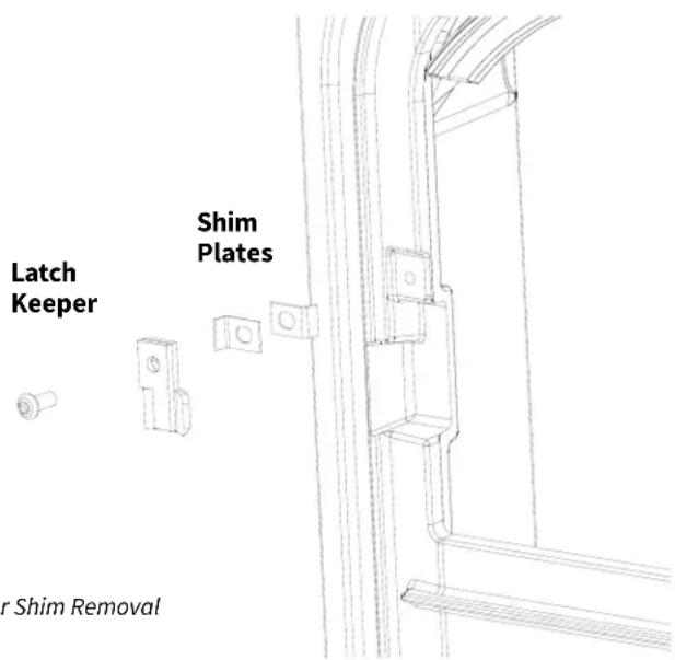
Fig. 6.2. Door Shim Removal
This page is intentionally left blank
6.7 Combustion System Maintenance
WARNING: BURNING JUNK MAIL OR COPIOUS AMOUNTS OF NEWSPRINT TO START THE FIRE CAN ACCELERATE FLY ASH COLLECTION ON THE COMBUSTOR AND NECESSITATE MORE FREQUENT CLEANING OF THE COMBUSTOR.
While catalytic combustor element is extremely durable, you can prolong its service life with routine inspections. The combustor itself is self-cleaning to an extent, however, fly ash will eventually accumulate within the element and upper combustion chamber. If you suspect combustor system performance is lagging, perform the following confirmation test.
- Burn the fire at medium to high settings for two or three hours at over 500°F to build a full bed of coals.
- Set primary air at medium to medium low.
- Confirm that monitor temperatures remain at 500^ F or higher. If the monitor temperature falls, the combustor may need to be cleaned or replaced.
- Repeat this test 2-3 times to confirm that the combustor is not functioning properly.
A non-functioning catalytic combustor must be replaced.
Regular Combustor Inspection
It is important to periodically monitor the operation of the catalytic combustor to ensure that it is functioning properly and to determine when it needs to be replaced. A non-functioning combustor will result in a loss of heating efficiency, and an increase in creosote and emissions.
Fig. 6.2. Use a soft brush to clean the combustor.

natural_image
Close-up of a perforated metal conveyor belt with a meshed metal sheet in the background (no text or symbols visible)Following is a list of items that should be checked on a periodic basis:
- The combustor should be visually inspected at least three times during the heating season to determine if physical degradation has occurred. The combustor can be visually inspected for damage and fly ash accumulation simply by opening the front door and looking up at the catalyst located above the secondary combustion baffle. Use a flashlight or head lamp to aid inspection.
- Use a soft brush to sweep any fly ash or other loose debris from the combustor cells. Figure 6.2.
- A shop vacuum may be used to carefully remove debris from within individual cell bodies. Use caution as the cell material is fragile.
- Inspect the combustor element for catalyst cell collapse and the insulation panels for surface degradation. Replace damaged components as they are critical to the proper functioning of the stove. Replacement parts are available from your authorized Jøtul dealer.
6.8 Combustor Replacement
Tools Required:
- 10 mm socket wrench with extension
- 3mm hex key
• Work gloves
The combustor components are accessed by removal of the top plate which is secured to the front plate by two M6 flange nuts with M6 fender washers, figure. 6.3, and two M6x40 set screws which are secured through the left and right sides.

natural_image
Close-up of a metal beam joint with two circular fasteners inserted, no visible text or symbolsFig. 6.3. Remove both top plate nuts located inside the front door opening.
Use the following instructions for combustor replacement:
- Use the 10mm socket wrench with extension to remove the two top plate M6 flange nuts with M6 fender washers located behind the front plate inside the stove as in figure 6.3.
- Use the 3mm hex key to remove the two M6x40 set screws on the left and right sides. See figure 6.4.
- Wearing gloves, grasp each side and lift the front of the top plate slightly off of the front and side plates. See figure 6.5.
- Wearing gloves, use both hands to carefully remove the Insulation Gasket (A) and large Insulation Panel(B) from the firebox. Figure 6.6.
- Simply lift the catalytic combustor to remove it from the compartment channel. Figure 6.7.
- Remove the Left and Right Side Refractory Members and Expansion Gasket from the combustion chamber. Figure 6.8.
- Reassemble the catalytic combustion components in the reverse order used to remove them.


Fig. 6.4. Remove M6x40 set screws from left and right sides.

natural_image
Person operating a portable stove or appliance on a platform (no visible text or symbols)Fig.6.5. Remove the top plate from stove.

Fig. 6.6. Insulation gasket (A) and Insulation panel (B).

natural_image
Interior view of a refrigerator with visible door, ventilation slots, and internal compartments (no text or symbols)Fig. 6.7. Lift combustor from the chamber.

Fig. 6.8. Left and Right Side insulation panel removal and replacement.
WARNING: DO NOT OPERATE WITH THE ASH DOOR OPEN. OPERATION WITH THE ASH DOOR OPEN CAN RESULT IN LARGE AMOUNTS OF FLY ASH AND CAN OVER-FIRE AND DAMAGE THE COMBUSTOR.
7. F 445
Illustrated Parts Breakdown
Purchase replacement parts only from a Jøtul Authorized dealer.

- Bolt, Hex Cap, M6x30, DIN 933 Blk .....9906
- Screw, Hex Hd Self-drill, #8 x .75" .....118405
- Gasket, LD2-250 129644
- Washer, Fender, M6 120004
- Nut, M6 Serrated Flange plain .....117968
- Screw, HWH SMA #8 x 1/2 SL Blk Ox ....117917
- Probe Retainer Cover, 22703792
- Bimetallic Coil Assembly, F 445 ......158178
- Washer, Flat M6 -.062 DIN 125A Plain ..117947
- Washer, Fender .250 x 1.500 dia. .....118029
- Sleeve, 10mm OD x 6mm ID x 10mm ...128934
- Probe Retainer .....226400
- Screw, Soc Set, cup pt, M6 X 10 .....04-117720
- Approval / Serial Number Plate .....n/a
- Bracket, Approval Plate, F 445 ......n/a
- Baffle Retainer .....227149
- Bolt, Hex Head Serr Flange M6x12 .....117130
- Bolt, M8x30, Serr Flange Hex ....117877
- Rear Air Riser, 105013
- Bolt, Hex Cap M6x60, DIN 933 8.8 .....99101
- Set Screw, M6 x 40 Hex Drive .....118288
- Bracket, Top/Side Pieces ......103713
- Screw, Socket Hd, M6x16, Blk Oxd .....9942
- Hinge pin, New Style, Black ......127075
- Wood Knob & Hardware .....151991
- Bolt M6x70 Cap 118420
- Spring, Door Handle ....126164
- Bolt, M8x45 Flange .....118421
- Washer, Door Handle 117587
- Gasket, Round, LD2-375, Graphite .....225695
- Insulation Blanket, Burn Plates .....227083
- Side Burn Plate 158387
- Bolt, M6x25 Flanged .....118019
- Bolt, M6 x 16, Serr. Hex Flange .....99625
- Inner Bottom, F 445 ......105031
- Ashpan 226966
- Gasket, LD2-250 ....129644
-
Ash House Ass'y 158380
-
Heat Shield, Bottom .....22703892
- Set Screw, M6 x 25 Hex Drive .....118070
- Latch Bolt 126228
- Handle, Complete, Ash Door .....155713
- Ash door Hinge Pin ....128408
- Door Catch with Dowel Pin ......22709392
- Screw, M6 x 14, Button Head.....118215
- Glass, Ceramic 5mm .....226852
- Latch Bolt, Front Door .....129208
- Gasket, Round, LD2-360 .....220748
- Front Door Handle, Curved .....10371292
- Glass Clip .....153620
- Screw, Cap, Low Socket Head, M6x8 ...118292
- Inner Front .....10503692
- Bolt, Hex Head, Serr Flange M6x20 .....117117
- Steel Spring U Nut, M6 118145
- E-Clip, 5 mm .....118272
72.. Air Control Lever 225625 - Bolt, Air Control Lever 118273
- Air Valve, 105016
- Inspection Cover 10385618
- Grate, F 445....105035
- Brick, Refractory, 9" x 3.375" x 1.25" ...220513
- Brick, Refractory, 9" x 4.50" x 1.25" .....129082
- Secondary Manifold .....105044
- Gasket, Secondary, Ledge ......226968
- Air Chamber Complete .....158386
- Gasket, Secondary, Base .....227064
- Insulation Blanket, Baffle Corner .....227088
- Gasket, Expansion ......226552
- Catalytic Combustor 158287
- Refractory member, Top ......226936
- Refractory member, Sides ......226935
- Insulation Strip 227084
- Gasket, Round, LD2-375 w/Adh. .....225696
- Side Clip / Hang Tab 128401
- Catalytic Combustor Monitor .....226609
- Gasket, Flat Self Adhesive 1/8 x 5/16 ...127215
- Shim, Door Catch 227168
8. Jøtul F 445 Holliday Woodburning Product Warranty
Effective January 1, 2019
This warranty policy applies to wood-burning products identified by Jøtul trade name, as set forth below.
A. LIMITED LIFETIME WARRANTY, parts only:
Jøtul North America Inc. (J∅TUL) warrants, to the original retail purchaser, that those baffle and air manifold components of the Jøtul Stove or Fireplace Insert specified above will be free of defects in material and workmanship for the life of the product. This warranty is subject to the terms, exclusions and limitations set forth below.
B. LIMITED FIVE YEAR WARRANTY - Cast Iron and Steel Components:
J∅TUL warrants, to the original retail purchaser, that those components of the Jøtul Stove or Fireplace Insert specified above will be free of defects in material and workmanship for a period of five (5) years from the date of purchase. This warranty is subject to the terms, exclusions and limitations set forth below.
C. LIMITED TWO YEAR WARRANTY - Enamel Finish:
J∅TUL warrants, to the original retail purchaser, the enamel finish on cast iron components of the Jøtul Stove or Fireplace Insert specified above against peeling or fading for a period of two (2) years from the date of purchase. This warranty is subject to the terms, exclusions and limitations set forth below.
D. LIMITED ONE YEAR WARRANTY - Electrical Components
(blowers, thermostatic switches, combustion monitor): J∅TUL warrants, to the original retail purchaser, that those components of the Jøtul Stove or Fireplace Insert specified above will be free of defects in material and workmanship for a period of one (1) year from the date of purchase. This warranty is subject to the terms, exclusions, and limitations set forth below:
J∅TUL will repair or replace (including parts & labor), at its option, any of the above components determined by J∅TUL to be covered by this warranty. You must, at your own expense, arrange to deliver or ship the component to an authorized Jøtul or Scan dealer and arrange for pickup or delivery of the component after repairs have been made. If, upon inspection, J∅TUL determines that the component is covered by this warranty, the repair or replacement will be made as set forth above. This warranty is not transferable and is extended only to, and is solely for the benefit of, the original retail purchaser of the Jøtul Stove or Fireplace Insert. This paragraph sets forth the sole remedy available under this warranty in the event of any defect in the Jøtul or Scan Stove or Fireplace.
The warranty period for any replaced component will be the remaining unexpired portion of the warranty period for the original component.
Please retain your dated sales receipt in your records as proof of purchase.
Exclusions and Limitations
Notice: This warranty is void if installation or service is performed by someone other than an authorized installer or service agency, or if installation is not in conformance with the installation and operating instructions contained in this owner's manual or local and/or national fire and building regulations. A listing of local authorized installers, service agencies and gas suppliers can be obtained from the National Fireplace Institute at http://www.nficertified.org/.
This warranty does not cover the following:
- Repair or replacement of parts that are subject to normal wear and tear during the warranty period or to parts that may require replacement in connection with normal maintenance. These parts include catalytic combustor*, paint, gaskets, burn plates, baffles, air manifolds, firebricks, fire grates, or glass (glass is only warranted against thermal breakage).
* The catalytic combustor is separately warranted by Jøtul North America, Inc. and secondarily by Applied Ceramics. See next page for warranty information and instructions. - Damage due to incorrect installations not in conformance with the installation instructions contained in this owner's manual or local and/or national fire and building regulations.
- Damage, including damage to enamel surfaces, caused by improper operation, over-firing, and/or misuse. Improper operation, such as burning the stove with the ash door open, can damage the stove. Over-firing occurs when any part of the stove glows red. Over-firing can also be identified by warped plates, rust-colored cast iron, paint pigment that has turned dusty white, or bubbling, cracking and discoloration of the enamel finish. Misuse includes, without limitation, use that is not in conformance with the operating instructions contained in this owner's manual.
- Damage due to service performed by an installer or service agency, unless otherwise agreed to in writing by J∅TUL.
- Damage caused by unauthorized modification, use or repair.
- Costs incurred by travel time and/or loss of service.
- Labor or other costs associated with the repair of components beyond the warranty period.
- Damage incurred while the Jøtul or Scan Stove or Fireplace is in transit.
IN NO EVENT SHALL J∅TUL, ITS PARENT COMPANY, SHAREHOLDERS, AFFILIATES, OFFICERS, EMPLOYEES, AGENTS OR REPRESENTATIVES BE LIABLE OR RESPONSIBLE TO YOU FOR ANY SPECIAL, INDIRECT, INCIDENTAL, CONSEQUENTIAL, PUNITIVE OR OTHER SIMILAR DAMAGES, INCLUDING, BUT NOT LIMITED TO, LOST PROFITS, LOST SALES, INJURY TO PERSON OR PROPERTY, OR DAMAGES TO A STRUCTURE OR ITS CONTENTS, ARISING UNDER ANY THEORY OF LAW WHATSOEVER. ALL IMPLIED WARRANTIES, INCLUDING THE IMPLIED WARRANTIES OF MERCHANTABILITY AND FITNESS FOR A PARTICULAR PURPOSE, OR OTHERWISE, ARE LIMITED IN DURATION TO THE LENGTH OF THIS WRITTEN WARRANTY. EXCEPT AS EXPRESSLY SET FORTH HEREIN, J∅TUL MAKES NO ORAL, WRITTEN OR OTHER WARRANTY WITH RESPECT TO J∅TUL OR SCAN STOVES OR FIREPLACES.
Some states do not allow the exclusion or limitation of incidental or consequential damages, or limitations on the length of implied warranties. Therefore, the above exclusions or limitations may not apply to you. This warranty gives you specific legal rights, and you may have other rights, which vary from state to state.
J∅TUL reserves the right to discontinue, modify or change the materials used to produce the Jøtul stove or fireplace. J∅TUL shall have the right to replace any defective component with substitute components determined by J∅TUL to be of substantially equal quality and price.
The dollar value of J∅TUL's liability for breach of this warranty shall be limited exclusively to the cost of furnishing a replacement component. J∅TUL shall not in any event be liable for the cost of labor expended by others in connection with any defective component. Any costs or expenses beyond those expressly assumed by J∅TUL under the terms of this warranty shall be the sole responsibility of the owner(s) of the Jøtul or stove or fireplace.
No dealer, distributor, or other person is authorized to modify, augment, or extend this limited warranty on behalf of J∅TUL. NO MODIFICATION OR CHANGE TO THIS WARRANTY WILL BE EFFECTIVE UNLESS IT IS MADE IN A WRITTEN DOCUMENT MANUALLY SIGNED BY AN AUTHORIZED OFFICER OF J∅TUL.
An authorized installer may have been provided with certain information related particularly to the Jøtul or stove or fireplace; however, no authorized installer or other person who may service the appliance is an agent of J∅TUL. No inference should be made that J∅TUL has tested, certified, or otherwise pronounced any person as qualified to install or service the appliance. J∅TUL shall not be liable or otherwise responsible for any error or omission by a person installing or servicing a Jøtul or stove or fireplace.
If you believe your Jøtul stove or fireplace is defective, you should contact your nearest authorized Jøtul dealer, who will process a warranty claim. IN ORDER TO QUALIFY FOR WARRANTY COVERAGE, J∅TUL MUST RECEIVE NOTICE OF A POSSIBLE DEFECT WITHIN SIXTY (60) DAYS OF THE DATE THE DEFECT IS FIRST DISCOVERED, OR REASONABLY COULD HAVE BEEN DISCOVERED.
This warranty is given by Jøtul North America, Inc., 55 Hutcherson Drive, Gorham, Maine 04038 USA
Jøtul High Flow TM Catalytic Combustor 10 – Year limited Warranty
Jøtul North America Inc. warrants to the consumer who purchases a Jøtul High Flow Combustor as a component in an EPA – Certified Jøtul solid fuel appliance, 100 % against defects in material and workmanship for a period of 10 years from the date of purchase.
Conditions and Exclusions:
- The Jøtul High Flow Combustor 10 Year Warranty is for the original purchaser of the Jøtul wood stove or wood insert and is non-transferable.
- The Jøtul High Flow Combustor 10 Year Warranty will be void if the combustor has been mechanically abused or if improper materials are burned in the stove or insert. See list below.
- The Jøtul High Flow Combustor 10 – Year Warranty does not apply to any other components of the Jøtul wood stove or wood insert.
- The Jøtul High Flow Combustor 10 – Year Warranty covers replacement of the original Jøtul High Flow Combustor due to defects in material and workmanship at no charge within the first 10 years.
-
If the Jøtul High Flow Combustor fails a second time within the 10 year period, the combustor will be covered for 50 % off the current retail.
-
Return the defective combustor to your local Jøtul Authorized Dealer who will submit a warranty claim on your behalf. All claims must be accompanied by proof of purchase showing the name of the selling dealer, date of purchase, Jøtul stove or insert model and the serial number of the unit, along with the consumer's name. All claims must be accompanied by clear photos of the damaged combustor.
- Related cost of replacement such as installation, travel, and shipping are excluded and the responsibility of the consumer.
- Return of the original Jøtul High Flow Combustor to Jøtul North America may be required.
- Any subsequent replacement combustor within the 10-year warranty, will be at the current retail price.
\*BURN UNTREATED WOOD ONLY. DO NOT BURN:
• Coal;
- Garbage;
- Synthetic fuel or logs;
- Material containing rubber, including tires;
• Material containing plastics;
- Waste petroleum products, asphalt products, paints, paint thinners or solvents;
- Materials containing asbestos;
- Construction or demolition debris;
- Railroad ties or pressure-treated wood;
- Manure or animal remains;
- Lawn clippings or yard waste;
- Salt water driftwood or other previously salt-water; saturated materials;
- Unseasoned wood;
- Colored paper, or
- Paper products, junk mail, cardboard, plywood, or particle board. (The prohibition against burning these materials does not include the use of fire starters made from paper, cardboard, saw dust, wax or similar substances for the purpose of starting a fire.)
- Burning of any of the materials listed above can result in the release of toxic fumes, cause smoke, or render the catalytic combustor permanently damaged and ineffective.
This page is intentionally left blank
This page is intentionally left blank
This page is intentionally left blank

Protect your investment! Don't miss out on the benefits of warranty coverage. Scan this QR code or visit jotul.com/warranty today to ensure peace of mind and timely support.
Jøtul pursues a policy of continuous product development. Products supplied may therefore differ in specification, color and type of accessories from those illustrated and described in this manual.

For Your Records...
Record the following information to help your dealer determine what you will need should your stove ever require parts or service.
The serial number and manufacturing date are indicated on the permanent label located on the back of the stove. You may also wish to attach your sales receipt to this manual for future reference.
Model: Jøtul F 445 Holliday
Serial Number:
Purchase Date:
Dealer:
Jøtul North America Inc.
55 Hutcherson Drive
Gorham, Maine 04038
USA
Jøtul AS
P.o. box 1411
N-1602 Fredrikstad,
Norway
www.jotul.us
130167-3
October 2024
Phone:
Installed by:
Date:
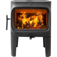
- Holliday
- Table of Contents
- Installation
- Chimney and Connector Requirements
- Connecting to the Chimney
- Clearances to Combustibles
- Operation
- Maintenance
- Parts Lists
- Accessories
- Rear Heatshield - 158374
- Blower Kit - 156431
- Outside Air Kit - 154335
- Floor Bracket Kit - 750304
- Stove-top Thermometer - 5002
- Leg Leveler Kit - 156096
- Universal Gasket Kit - 157050
- Replacement Catalyst - 158287
- Standards
- Check Building Codes
- Combustion Specifications
- Safety Notices
- DO NOT OVERFIRE THIS HEATER.
- WARNING:
- WARNING!
- Assembly Before Installation
- Chimney and Chimney Connector Requirements
- Chimney Connector
- General Chimney Requirements
- Chimney Considerations
- Masonry Chimneys
- Prefabricated Chimneys
- Chimney Height
- Wall Pass-throughs
- In the U.S:
- Common Method:
- Masonry Chimney Thimble
- In Canada:
- Hearthmount Into a Masonry Fireplace
- Prefabricated Chimneys
- Floor Protection Requirements
- The F 445 requires a listed UL 1618 floor protection as specified below in any installation unless installed on concrete over earth.
- In the U.S.:
- The hearth protection surface must extend continuously in front of the stove:
- Alternate Floor Protection
- Example:
- Clearances to Walls and Ceilings
- Using Shields to Reduce Clearances
- Alcove Installation
- Jøtul F 445 Clearances
- Mobile Home Installations
- CAUTION: The structural integrity of the mobile home, floor wall and ceiling/roof must be maintained.
- WARNING: DO NOT INSTALL THE STOVE IN A BEDROOM OR SLEEPING AREA.
- Combustion Efficiency
- Minimize Carbon Monoxide Emissions
- Wood Fuel and Performance
- Use dry wood.
- BURN UNTREATED WOOD ONLY. DO NOT BURN:
- F 445 Control Functions
- Control Settings and Performance
- Burn Rate Air Control Setting Blower Speed
- Use of a Stove-top Thermometer
- Using the Combustor Monitor
- Visual Monitoring
- Stove Break-In Procedure
- Starting and Maintaining a Fire
- Traditional Fire Building
- Top-Down Fire Building - See figure 5.9.
- Creosote and Soot Formation and the Need for Removal
- Adding Fuel
- Warning: Use only Jøtul authorized parts. Do NOT use substitute glass.
- Annual Stove Inspection
- Ash removal
- Chimney System
- Enamel Care
- Glass Care
- Cleaning
- Ceramic Glass Replacement 226852
- Gaskets
- Door Latch Adjustment
- Tools Required:
- Gasket Replacement
- F 445 Gaskets
- Combustion System Maintenance
- Regular Combustor Inspection
- Combustor Replacement
- F 445
- Illustrated Parts Breakdown
- Jøtul F 445 Holliday Woodburning Product Warranty
- LIMITED LIFETIME WARRANTY, parts only:
- LIMITED FIVE YEAR WARRANTY - Cast Iron and Steel Components:
- LIMITED TWO YEAR WARRANTY - Enamel Finish:
- LIMITED ONE YEAR WARRANTY - Electrical Components
- Exclusions and Limitations
- This warranty does not cover the following:
- Jøtul High Flow TM Catalytic Combustor 10 – Year limited Warranty
- Conditions and Exclusions:
- \*BURN UNTREATED WOOD ONLY. DO NOT BURN:
- For Your Records...
Brand : JOTUL
Model : F 445 Holliday CF
Category : Heating