
GI 550 DV - Wood stove JOTUL - Free user manual and instructions
Find the device manual for free GI 550 DV JOTUL in PDF.


| Product Type | Direct Vent Gas Fireplace Insert |
| Brand | Jøtul |
| Model | GI 550 DV |
| Fuel Types | Natural Gas (factory set) or Propane (with conversion kit) |
| Maximum Input (NG) | 38,000 BTU/hr |
| Minimum Input (NG) | 21,900 BTU/hr |
| Maximum Input (LP) | 30,000 BTU/hr |
| Minimum Input (LP) | 20,000 BTU/hr |
| Steady State Efficiency (NG) | 79% |
| Steady State Efficiency (LP) | 81.2% |
| AFUE Efficiency (NG) | 65.2% |
| AFUE Efficiency (LP) | 65.4% |
| Ignition | Standing Pilot with Piezo Ignitor |
| Venting System | Co-linear 3" flexible liners, vertical only (no horizontal runs) |
| Minimum Fireplace Opening Width | 34.5" (876 mm) without leveling brackets; 36" (914 mm) with |
| Minimum Fireplace Opening Height | 24" (610 mm) standard; up to 26" with Scan 70i riser |
| Minimum Fireplace Depth | 17" (432 mm) |
| Blower | Built-in, 122 CFM, heat-activated (snapstat) with manual/auto switch |
| Controls | On/Off/T-Stat switch, variable HI/LO regulator |
| Optional Accessories | Wall thermostat, remote control, brick panels, multiple surround kits |
| Warranty (Cast Iron & Steel) | 5 years |
| Warranty (Burner & Panels) | 2 years |
| Warranty (Gas & Electrical) | 1 year |
| Safety Certifications | ANSI Z21.88-2009, CSA 2.33-2009, CAN/CGA 2.7-M91, CSA P.4.-01 |
Frequently Asked Questions - GI 550 DV JOTUL
User questions about GI 550 DV JOTUL
0 question about this device. Answer the ones you know or ask your own.
Ask a new question about this device
Download the instructions for your Wood stove in PDF format for free! Find your manual GI 550 DV - JOTUL and take your electronic device back in hand. On this page are published all the documents necessary for the use of your device. GI 550 DV by JOTUL.
USER MANUAL GI 550 DV JOTUL
Installation and Operation Instructions
WARNING: If the information in these instructions is not followed exactly, a fire or explosion may result causing property damage, personal injury or loss of life.
- Do not store or use gasoline or other flammable vapors and liquids in the vicinity of this or any other appliance.
-
WHAT TO DO IF YOU SMELL GAS
-
Do not try to light any appliance.
- Do not touch any electrical switch; do not use any phone in your building.
- Immediately call your gas supplier from a neighbor's phone. Follow the gas supplier's instructions.
• If you cannot reach your gas supplier, call the fire department. - Installation and service must be performed by a qualified installer, service agency or the gas supplier.
- In the Commonwealth of Massachusetts, a carbon monoxide (CO) detector shall be installed in the same room as the appliance.
This appliance may be installed in an aftermarket, permanently located, manufactured home (USA only) or mobile home, where not prohibited by local codes.
This appliance is only for use with the types of gas indicated on the rating plate. A conversion kit is supplied with the appliance.
ATTENTION : CES INSTRUCTIONS DOIVENT DEMUERER AVEC LE PROPRIÉTERE D'UNE MAISON.
HOT GLASS WILL CAUSE BURNS.
DO NOT TOUCH GLASS UNTIL COOLED.
THIS OWNER'S MANUAL PROVIDES INFORMATION TO ENSURE SAFE INSTALLATION AND EFFICIENT, DEPENDABLE OPERATION OF YOUR FIREPLACE INSERT. PLEASE READ THESE INSTRUCTIONS IN THEIR ENTIRETY AND MAKE THEM AVAILABLE TO ANYONE USING OR SERVICING THIS GAS INSERT.
DO NOT ATTEMPT TO ALTER OR MODIFY THE CONSTRUCTION OF THIS APPLIANCE OR ITS COMPONENTS. ANY MODIFICATION OR ALTERATION WILL VOID THE WARRANTY, CERTIFICATION AND LISTING OF THIS APPLIANCE.
THIS HEATER MUST BE INSTALLED AND MAINTAINED BY A QUALIFIED SERVICE AGENCY.
Suggested Tools for Installation and Service
• External regulator (for Propanc only)
- Piping which complies with local code
- Manual shut off valve - T-Handle required in Massachusetts
- Sediment trap - if required by code
- Tee joint
- Pipe wrench
- Pipe scalant
• 10 mm open end wrench
• Work Gloves - Safety glasses
• Torx T-20 screwdriver - Tin snips
• 1/2',7/16' oper end wrench
• Phillips head screwdriver
- Flat head screwdriver
- 1/4" nut driver
Installation Requirements for the Commonwealth of Massachusetts
THIS PRODUCT MUST BE INSTALLED BY A LICENSED MASTER OR JOURNEYMAN PLUMBER OR GAS-FITTER WHEN INSTALLED IN THE COMMONWEALTH OF MASSACHUSETTS.
-
If there is not one already present, on each floor level where there are bedroom(s), a carbon monoxide detector and alarm shall be placed in the living area outside the bedroom(s). The carbon monoxide detector shall comply with NFPA 720 (2005 Edition).
-
A carbon monoxide detector shall: a) Be located in the room that houses the appliance or equipment; b) Be either hard-wired or battery powered or both; and c) Shall comply with NFPA 720 (2002 Edition).
-
A Product-approved vent terminal must be used, and if applicable, a Product-approved air intake must be used. Installation shall be in strict compliance with the manufacturer's instructions. A copy of the installation instructions must remain with the appliance or equipment at the completion of the installation.
NATIONAL
FIREPLACE
INSTITUTE

CERTIFIED
www.nfi:certified.org
We recommend that our gas products be installed and serviced by professionals who are certified in the U.S. by the National Fireplace Institute® (NFI) as NFI Gas Specialists.

Table of Contents
Installation & Service Tools ..... 2
Specifications....4
General Information....5
Safety Information 6
Installation
Fireplace Requirements 7
Hearth Protection 8
Clearances 8
Masonry Fireplaces ....10
Prefabricated Fireplaces.....11
Vent Requirements ....13
Fireplace Assembly
Gas Connection....14
Gas Pressure....15
Fuel Conversion....16
Wall Thermostat 18
Remote Control....18
Blower Power Requirement ..... 18
Optional Wall Panel Kits ....19
Log Set Installation 20
System Check....21
Surround Assembly....22
Operation
Burner Controls 23
Blower Controls 24
Maintenance
Annual Cleaning 24
Glass Replacement....25
Illustrated Part Breakdown ..... 26
Replacement Parts List....27
Appendix A: Remote Installation ....28
Service Log 30
Lighting Instructions 31
Unpacking the Fireplace
- A Miscellaneous Hardware Kit is packed within the right side compartment of the firebox. It contains:
• Installation / Operation manual
• Glass Frame Latch Release tool
• Fuel Conversion Kit, LP
• Leg Leveller Brackets, - left and right, 2 each -
1c x 1/2" Sheet metal screws for brackets, 8
- Rock Wool
- The Log Set is packaged separately from the firebox. Use the Latch Release tool to remove the fireplace glass frame in order to install the log set and any other accessories.
- See the cut-away view in fig. 7 below to locate the right and left spring latches on the underside of the firebox floor. Release each latch by engaging the tangs of the tool with the latch throat, pulling it forward and down.
- Pull the Glass Frame away from the Firebox and lift to disengage it from the retaining lip at the top of the Firebox. Set the glass out of the way.
- Do not unpack the log parts until you are ready to install them.

Figure 1. Pull each Spring Latch out and down to disengage it from the Glass Frame.
Jøtul GI 550 DV / Scan 70i Direct Vent Gas Fireplace Insert

Manufactured and Distributed by: Jotul North America Graham, Maine USA

Test Standards
This appliance complies with National Safety standards and is tested and listed by Intertek Testing Services of Middleton, Wisconsin.
In addition, the Jotul GI 550 DV gas fireplace insert has been listed and listed as a direct vent gas fireplace heater and listed to ANSI Z21.88-2009, CSA 2.33-2009, CAN/CGA 2.7-M91, and CSA P.4.-01.2 for Canada.

Specifications
Input Rates
Natural Gas
38,000 A.U/hr maximum input 21,900 BTU/hr minimum input
Propane
30,000 BTU/hr. maximum input 20,000 BTU/hr. minimum input
| Inlet Pressure: | MIN. | MAX. |
| Natural Gas: | 5.0 WC (1.24 kPa) | 7.0 WC (1.74 kPa) |
| Propane: | 12.0 WC (2.98 kPa) | 16.0 WC (3.98 kPa) |
Manifold Pressure: MIN MAX.
| Natural Gas: | 1.2 WC (0.29 kPa) | 3.B WC (0.93 kPa) |
| Propane: | 2.9 WC (0.72 kPa) | 11.0 WC (2.74 kPa) |
| Steady State Efficiency: 79% / NG | 81.2% / LP |
| A.F.U.E. Efficiency: 65.2% / NG | 65.4% / LP |
Piezo Ignitor / Standing Pilot
This fireplace is equipped to burn natural gas only. If propane gas is desired, the fireplace must be converted for use with propane. Install the LP Conversion Kit included with the fireplace according to the instructions in this manual.
Accessories
Basket Screen (for Cast Iron Double Doors) ..... #156426
Reversible Brick Panel Kit. Corduroy Bfk/Gry ....#156427
Reversible Brick Panel Kit Antique/Border....#156428
Fuel Conversion Kit - NO to LP 4156446
Fuel Conversion Kit - LP to NG, 0:50447
High Altitude Adjustment Kit - LP....#156451
High Altitude Adjustment Kit·NG....#:56452
Wall Thermostat. #75003
Remote Control \$129706
Cast Iron Surrounds
40" Wide x 3c" High. (32" w/ plinth option) Matte Black Paint....../../../../../../../../../../../../../../../../../../../../../../../../../../../../../../../../../../../../../../../../../../../../../../../../../../../../../../../../../../../../../../../../../../../../../../../../../../../../../../../../../../../../../../../../../../../../../../../../../../../../..
Cast Iron Double Doors
Matte Black ....#351057 Blue Black Enamel ....#351058 Jolul Iron ....#351059
Steel Surround Kits
Simple Surround, 44" × 32" ..... #15722B
Wide Surround Panel 46 1/2 46 Wide x 33" High, (35" w/ plintn extensions) Black Powder Coa: ..... #156429
Irimmable Surround, 46 1/2" x 33" Matte Black Paint ....\$157927
Grand Forge - 44" x 32" Charcoal Gray ....#156420 Natural Iron ....#156421 Black Powder Coat ....#175622
Cathedral Arch Doors & Surround w/ Screen, 44" x 32" Charcoal Gray ....#156423 Natural Iron ....#156424 Black Powder Cual ....#156425
Scan 70i Sliding Glass Panel & Surround, 44" x 31" for 1" Riser - includes Mantel Heat Shield Black Powder Coat .......#K:56443 Stainless Steel.......#K:56443
Scan 70: Sliding Glass Panel & Surround, 64" x 32" for 2" Riser - includes Mantel Heat Shield Black Powder Coat ....#K156462 Stainless Steel ....#K156463
* Custom: sizes available. See your dealer for details.
General Information
IMPORTANT: SAVE THESE INSTRUCTIONS.
-
The installation and repair of this appliance must be done by a qualified service person. Failure to properly install and maintain this heater could result in an unsafe or hazardous installation, which may result in a fire, explosion, property damage, personal injury or loss of life.
-
This appliance should be inspected before use and at least annually. More frequent cleaning may be required due to excessive lint from carpeting, bedding material, etc. It is imperative that control compartments, burners and circulating air passageways of the appliance be kept clean.
- This appliance may be installed in an aftermarket permanently located, manufactured (mobile) home, where not prohibited by local codes.
This appliance is only for use with the type(s) of gas indicated on the rating plate. This appliance is not convertible for use with other gases, unless a certified kit is used.
- The installation must conform to local codes. Your local Jotul authorized dealer can assist you in determining what is required in your area for a safe and legal installation. Some areas require a permit to install a gas burning appliance. Always consult your local building inspector or authority having jurisdiction to determine what regulations apply in your area.
In the absence of local codes, the installation requirements must comply with the current National codes. In the U.S., these requirements are established in the National Fuel Code, ANSI Z223.1 (NFPA 54). In Canada, the codes have been established in CAN/CGA B49 Fuel Installation Code.
- Do not operate this fireplace if any part of it has been under water. Immediately call a qualified service technician to inspect the heater and to replace any part of the control system and any gas control which has been under water.
- Do not operate the fireplace with the glass front removed, cracked or broken. Replacement of the glass should be done by a licensed or qualified service person. Orly remove glass for routine service. Always handle glass carefully.
7 Notify your insurance company before proceeding with installation of this fireplace.
Safety Information
■ Due to the high operating temperatures this appliance should be located out of traffic and away from furniture, draperies, etc. Maintain proper clearance to combustible mantels and fireplace trim.
Children and adults should be alerted to the hazards of high surface temperatures and should stay away to avoid burns or clothing ignition.
■ Young children should be supervised while they are in the same room as the appliance. Toddlers, young children and others may be susceptible to accidental contact burns. A physical barrier, such as a child guard, is recommended to be used if there are at-risk individuals in the house. To restrict access to a fireplace or stove, install an adjustable safety gate to keep toddlers, young children and other at-risk individuals out of the room and away from hot surfaces.
■ Any safety screen or guard removed for servicing an appliance must be replaced prior to operating the appliance.
Clothing or other flammable materials should not be placed on or near the fireplace.
■ Be aware of electrical wiring locations when cutting holes in walls and ceilings for termination.
■ The blower must be electrically grounded in accordance with local codes or, in the absence of local codes, with the current ANSI/NFPA 70, National Electrical Code or CSA C22.1-Canadian Electrical Code.
■ The Blower is supplied with a three-prong (grounding) plug for protection against shock hazard and should be plugged directly into a properly grounded three-prong receptacle.
DO NOT CUT OR REMOVE THE GROUNDING PRONG FROM THE PLUG.
■ Always disconnect the power supply when performing routine service on the fireplace.
Installation Requirements
This insert can be installed in most: solid fuel burning fireplaces of either masonry construction or a prefabricated factory built fireplace.
Prior to any installation, the existing chimney exhaust flue must be thoroughly cleaned and completely inspected by a qualified chimney sweep or fireplace service person.
Do not install this insert into a chimney that is damaged. Any repairs must be made prior to installing the insert. If you are unsure of the condition of your fireplace and chimney, contact a professional fireplace technician or your local authorized Jotul dealer for professional assistance.
DO NOT REMOVE BRICKS OR MORTAR FROM THE FIREPLACE OR CHIMNEY STRUCTURE. However, masonry or steel may be removed from the smoke shelf and adjacent damper frame area to accommodate installation of a chimney liner, provided that their removal will not weaken the structure of the fireplace or chimney, and will not reduce protection for combustible materials.
If the fireplace has been modified to accommodate installation, use anchors or masonry rails to attach the metal Fireplace Conversion Notice Plate to the back wall of the masonry fireplace firebox where it will be readily seen should the insert be removed.
THIS APPLIANCE MUST NOT BE CONNECTED TO A CHIMNEY OR FLUE SERVING ANY OTHER APPLIANCE OF ANY KIND.
All venting components must be installed in accordance with the terms of their listing and manufacturer's instructions. Refer to the pipe manufacturer's instructions for proper pipe clearances.
This fireplace insert is specifically designed for use with 3" Type 3 vent pipe components or a Listed Flexible gas liner. See the Appendix on page 28 for a complete list of vent pipe manufacturers whose products are approved for use with this appliance.
Leg Leveler Bracket Note:
Two right and left brackets with mounting hardware are included in the Miscellaneous Kit. Installation of the brackets allows the insert to be raised up to 2 1/2" of" of the heart".
Note that use of the brackets will require a larger minimum tireplace width at both the front and rear as shown below. Also note that use of the levelling brackets will affect required minimum clearance to combustible top trim and mantle construction. See the figures and tables on pages 8 and 9.


Figure 2. Firebox dimensions.
Minimum Fireplace Requirements
This fireplace insert has been specifically designed to be installed into a solid fuel burning factory built fireplace or a code approved solid fuel burning masonry fireplace with a tile flue liner. An acceptable fireplace cavity must have the minimum dimensions specified in fig. 3.
Do not modify or alter the construction of the gas insert or any of its components to enable it to fit into a fireplace. Any modification of the insert will void the warranty, certifications and approvals of the unit and could be dangerous.
Install Leg Leveling Brackets
- Oriented as you face the insert, install the right and left mounting brackets to the sides of the insert using the #10 x /2" screws provided at the height appropriate to your installation requirements.
![graph TD A["A"] --> C["C"] C --> D["D"] D --> B["B"] B --> E["E"] E --> A style A fill:#f9f,stroke:#333 style B fill:#ccf,stroke:#333 style C fill:#cfc,stroke:#333 style D fill:#fcc,stroke:#333 style E fill:#cff,stroke:#333](/content/2026/05/957764/images/19f23bc447a1918c87fab23bad57deaa3aa961a86f5536573f3af83fa7adeeb6.jpg)
A: Opening Width = 341/2" (876 mm) with leveling brackets = 36" (914 mm)
B: Opening Height - 24" (610 mm)
w/ Scan 70i, 1" r set = 25" (635 mm)
w/ Scan 70i, 2" r set = 26" (660 mm)
C: Back Wall Width = 22" (559 mm) with leveling brackets = 23" (584 mm)
D: Back Wall! Height = 23" (584 mm)
w/ Scan 70i 1" riser = 24" (610 mm)
w/ Scan 70i 2" riser = 25" (635 mm)
C: Depth = 17" (432 mm)
Figure 3. Minimum fireplace dimensions - GI 550 DV.
Clearance to Combustible Materials
A combustible material is anything that can burn (i.e. sheet rock, wallpaper, wood, fabrics etc.). These surfaces are not limited to those that are visible and also include materials that may be behind non-combust bles.
If you are unsure of the combustible nature of a material, consult your local fire officials. "Fire Resis Lant" materials are considered combustible: they are difficult to ignite, but will burn. "Fire-rated" sheet rock is also considered combustible.
The following clearances and hoarts specifications are the minimum requirements for installation into a masonry or factory built fireplace. Mantel and wall clearances will vary, depending upon the fireplace facing and riser height, if needed. Use the tables and illustrations in figs. 4 and 5 to determine the minimum clearances for your installation.
Hearth Requirements
Hearth protection in front of the GI 550 DV must be composed of any noncombustible material extending a minimum 36" wide. Hearth protection must extend at least 16" forward of the firebox glass panel with the following exception:
Cast Iron surrounds without Flinth: the hearth protection must extend 36" x 18".
See Fig. 4, Table 1.

Figure 4. Hearth, Trim and Wall clearances.
Fireplace Facing Options
Jøtul Cast Iron Surround - 40" W x 30" P w/ Plinth - 40" W x 32" H w/ Optional Wide Surround Panel - 46 1/2" W x 33" H w/ Plinth Extensions - 46 1/2" W x 35" H
Steel Door Kits - includes Surround Panels 44"W x 32"H
SCAN 7ai Surround Assembly -with 2" Riser: 44"W x 31" H -with 2" Riser: 44"W x 32" H
| Surround Type | A | B | C | D | E |
| Jetul Cast Iron | 18" | 18" | 21" | 44" | 42" |
| Jetul Cast Iron w/ Plinth | 18" | 16" | Surrounds | 44" | 44" |
| Steel Double Doors | 18" | 16" | 21"24 3/4"w/ Wide | ||
| Scan 70i w/ Mantel Heat Shield | 18" | 16" | 22" | 46" | 44" |
| 23" | 46" | 44":1"Riser45":2"Riser | |||
| Scan 70i without Mantel Heat Shield | 18" | 16" | Use noncombustible materials only. | 46" | Use noncombustible materials only. |
Table 1. Hearth, Trim and Wall clearances.
A: Hearth Protection Width - 18" from center line.
B: Hearth Protection Depth: 18" for Cast Iron Surround without Phinth 16" for all other configurations
C: Side trim Clearance, up to 6" thick. Shown measured from fireplace center line = 1" from Cast Iron Surround and o" (zero clearance) from Steel Surrounds.
D: Side Room Wall Clearance shown measured from the fireplace center line = 24" from Surround.
Γ: Top Trim Clearance = Same as 3.5" deep mantel-See fig. 5.
Mantel Clearance Requirements
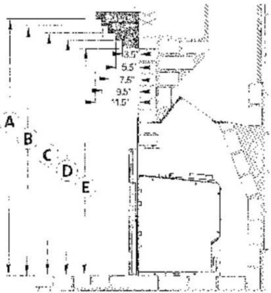
Figure 5. Minimum Mantel Clearances shown measured from the nearth surface to the mantel surface.
| Surround Type | A | B | C | D | E |
| Jotul Cast Iron | 28" | 46 1/2" | 45" | 43 1/2" | 42" |
| Jotul Cast Iron w/ Plinls | 50" | 48 1/2" | 47" | 45 1/2" | 44" |
| Steel Double Doors | 50" | 48 1/2" | 47" | 45 1/2" | 44" |
| With 1" Riser | |||||
| Scan 70i w/ Mantel Heat Shield | 50" | 48 1/2" | 47" | 45 1/2" | 44" |
| With 2" Rise | |||||
| 51" | 49 1/2" | 48" | 45 1/2" | 45" | |
| Scan 70i without Manbel Heat Shield | Use noncombustible materials only. | ||||
Table z. Mantel clearances.
Vent Guidelines
- All vent components must be installed in accordance with the listing terms and manufacturer's instructions.
- Vent Height: Measured from the top of the insert to the top of the termination cap. Minimum: no less than 10' Maximum: no greater than 35'.
The minimum vent height above the roof or adjacent walls is specified by building codes. As a general guide, follow the Gas Vent Rule on page 12.
• HORIZONTAL RUNS ARE NOT PERMITTED ANY-WHERE IN THE VENTING SYSTEM.
- Venting liners used on this appliance may not be less than 5" in diameter or greater than 3" in diameter.
- Any unused flue or masonry enclosure can be used as a passageway for venting provided the flue is relined using §° Listed flexible gas liner.
- The remaining space around the liner in a masonry or zero-clearance flue CANNOT be used to vent any other appliance.
- Flexible liner components may not be exposed in any living space.
- Installation of any components not manufactured or approved by Jotul or failure to meet all clearance requirements will void all warranties and could result in property damage, bodily injury, or serious fire.
- Never modify any venting component, or use any damaged venting product.
- THE GAS APPLIANCE AND VENT SYSTEM MUST BE VENTED DIRECTLY TO THE OUTSIDE OF THE BUILDING, AND NEVER ATTACHED TO A CHIMNEY SERVING ANOTHER SOLID FUEL OR GAS-BURNING APPLIANCE.
- Use vent component supplied by one of the vent manufacturers listed on page 5 of this manual. Do not mix components from different manufacturers in a single installation.
Masonry Fireplaces
A solid-fuel fireplace chimney must be clean and in good working order. It must be constructed of no-combustible materials. Chimney clean-outs must fit properly.
When installing the Universal GI 550 DV gas insert into a masonry fireplace, the insert will be vented through dual 3" flexible gas aluminum liners.
This co-linear installation includes a pair of 3" flex ducts that run from the insert completely through the existing chimney to the termination cap.
One liner is attached to the Exhaust Outlet on the back of the unit and will carry the exhaust gases to the outside of the house. This exhaust liner must be directly connected to the unit and run the full length of the chimney. See fig. 6.
The other 3" liner will be attached to the Air Intake Collar on the back of the unit to provide fresh air for combustion. The Intake Collar is labeled for easy identification. The liner must extend a minimum of 6' off the back of the unit and extend through the camper area of the fireplace into the tile liner of the chimney. This liner can also extend the full length of the chimney and connect to the termination cap.
IMPORTANT
If the intake flex does not extend the full length of the chimney, forming a direct connection between the unit and the termination cap. A METAL BLOCK OFF PLATE MUST BE INSTALLED to seal the air intake from room air. Normally this sealing plate will be installed within the existing fireplace damper area. See fig. 6. The sealing plate is not necessary if a direct connection is made between the cap and the fireplace. WARNING! Avoid cross venting the insert. Before installation, label both ends of the exhaust flex pipe to ensure connection to the appropriate collars on the fireplace unit and vent termination cap.
Cutting of any sheet metal parts on a solid-fuel f replace is prohibited.
Smoke selves, shields, and baffles may be removed if attached with mechanical fasteners.
IMPORTANT NOTICE:
THE USE OF AN EXISTING CHIMNEY AS AN AIR INTAKE IS NOT COVERED UNDER THE ANSI Z21.88-1999-CSA 2.33-M99 TEST METHODS AND RESULTING ITS/WHI PRODUCT CERTIFICATION. THE CODE AUTHORITY HAVING JURISDICTION MUST BE CONSULTED PRIOR TO PROCEEDING WITH THIS INSTALLATION METHOD.
Masonry Fireplace Vent Installation
- Measure height of the chimney to fireplace operating. Determine if both the intake and exhaust will be extended to the top of the chimney.
- Use tin ships to cut the appropriate lengths of flex for both the intake and exhaust.
- Attach the appropriate ends of the flex to the chimney termination kit.
- Drop the liners down the chimney from the top and rest the termination kit atop the chimney.
- Seal the chimney termination kit to the top of the chimney flue with high temperature sealant.
- Secure the appropriate DIRECT VENT CAP to the termination k't
- Inside the fireplace, fully extend the flex liner pipe and cut off the excess so that the liners hang approximately 15" from the floor of the fireplace.
- If the Air Intake pipe will not be attached to the chimney termination kit: (See IMPORTANT NOTICE on this below.)
a. It will be necessary to install: a minimum length of 6 fl. flex pipe up into the flue.
b. A metal damper block off plate must be constructed and installed in the fire place damper area to completely seal off the flue from the room. Cut holes in the plate for both the intake and exhaust flex pipes.
c. A direct vent cap is required to bring fresh air into the chimney flue and Air Intake flex pipe.
a. Attach the Fireplace Conversion Notice to the back of the fireplace if appropriate.
CANADA REQUIREMENT: Both the intake and the Exhaust liners must extend the full length of the chimney and be securely connected to both the unit and the termination kit.
If the fireplace has been modified to accommodate it stallation, use anchors or masonry nails to attach the metal Fireplace Conversion Notice Plate supplied with this unit to the back wall of the masonry fireplace firebox where it will be readily seen should the insert be removed.

Figure C. Masonry Fireplace Venting Configuration.
WARNING:
FAILURE TO POSITION THE PARTS IN ACCORDANCE WITH THIS DIAGRAM OR FAILURE TO USE ONLY PARTS SPECIFICALLY APPROVED WITH THIS APPLIANCE MAY RESULT IN PROPERTY DAMAGE OR PERSONAL INJURY.
Prefabricated Fireplaces
A prefabricated fireplace chimney must be clean and in good working order. It must be constructed of noncombustible materials. Chimney clean-outs must fit properly.
A factory-built prefabricated fireplace will require a few modifications before installation of the fireplace insert.
Modification Steps:
- Remove any fuel grate or other components attached to the firebox. On most models the fire grate is attached to the unit with brackets which should be cut or pried off.
- Remove the damper assembly. This includes the damper blade, handle and any linkage. Two 3" liners must be able to pass through the damper area.
- Remove any fire screen or door assembly. This is usually done by removing a support rod on the inside of the fireplace frame. Smoke shelves, shields, and baffles can be removed if attached with mechanical fasteners.
- If there is a metal ash lip, it too should be removed to allow the unit to sit flat in the fireplace. Be sure to reinstall any screws removed.
IMPORTANT:
BEFORE STARTING THIS INSTALLATION, MAKE SURE THAT A GAS LINE CAN BE INSTALLED OR IS INSTALLED TO THE FIREBOX. THIS SHOULD ONLY BE DONE BY A QUALIFIED OR LICENSED PLUMBER OR GAS FITTER.
The GI 550 DV gas insert is specifically designed to be vented using a co-linear system.
Installation includes a pair of 3" flex ducts that run from the insert completely through the existing chimney to the termination cap. See Figure 7, page 12.
One liner is attached to the exhaust port on the back of the unit and will carry the exhaust gases to the outside of the house. This exhaust liner must be directly connected to the unit and run the full length of the ch mney.
IMPORTANT NOTICE:
THE USE OF AN EXISTING CHIMNEY AS AN AIR INTAKE IS NOT COVERED UNDER THE ANSI Z21.88-1999-CSA 2.33-Mgg TEST METHODS AND RESULTING ITS/WHI PRODUCT CERTIFICATION. THE CODE AUTHORITY HAVING JURISDICTION MUST BE CONSULTED PRIOR TO PROCEEDING WITH THIS INSTALLATION METHOD.
The other 3" liner will be attached to the intake port on the back of the unit and will provide fresh air for combustion to the unit. This liner must extend a minimum of 6 ft. off the back of the unit and extend through the damper area of the fireplace and into the first section of pipe. This liner can also extend the full length of the chimney and connect to the termination cap. See figure 7.
IMPORTANT:
If the intake flex does not extend the full length of the chimney and connect to the unit and the termination cap - THEN A METAL BLOCK OFF PLATE MUST BE CONSTRUCTED AND INSTALLED ABOVE THE UNIT PRIOR TO THE END OF THE INTAKE FLEX (normally at the damper area).
Cutting of any sheet metal parts on a solid-fuel fireplace is prohibited.
If the factory-built fireplace has no gas access hole(s) provided, an access hole 1.5" diameter or less may be drilled through the lower sides or bottom of the firebox in a proper workmanship-like manner. This access hole must be plugged with noncombustible insulation after the gas supply line has been installed.
CANADA REQUIREMENT: Both the Intake and the Exhaust liners must extend the full length of the chimney and be securely connected to both the unit and the termination kit.
If the fireplace has been modified to accommodate installation, use anchors or masonry nails to attach the metal Fireplace Conversion Notice Plate supplied with this unit to the back wall of the masonry fireplace firebox where it will be readily seen should the insert be removed.
The minimum vent height above the roof or adjacent walls is specified by major building codes. A general guide to follow is the Gas Vent Rule below.
GAS VENT RULE
| ROOT SLOPE Flat to 6/12 | Minimum Height From Roof | |
| 10" | 0.3M | |
| Over 7/12 to 9/12 | 2'0" | 0.6M |
| Over 10/12 to 12/12 | 4'0" | 5.2M |
| Over 12/12 to 16/12 | 6'0" | 1.8M |
| Over 7/12 to 21/12 | 8'0" | 2.4M |

Figure 7. Factory-built fireplace vent configuration with direct connection to chimney termination cap as required in Canada.
Prefabricated Fireplace Vent Installation
- Measure height of the chimney to fireplace opening. Determine if both the intake and exhaust will be extended to the top of the chimney
- Cut the appropriate lengths of flex for both the intake and exhaust.
- If the Intake flex will be attached to the chimney lernination kit: Attach the appropriate ends of the flex to the chimney lernination kit, Label the end of the exhaust pipe
- Drop the liners down the chimney from the top and rest the termination kit atop the chimney.
- Seal the chimney termination kit to the top of the chimney pipe with high temperature sealant.
- Secure the appropriate DIRECT VENT CAP to the termination kit.
- Inside the fireplace, fully extend the flex and cut off the excess flex so that the liners hang approximately 15" from the floor of the fireplace.
- If the intake flex is NOT attached to the chimney termination kit: See NOTICE on page 12.
A. It is necessary to install a minimum 6 foot length of flex pipe into the flue for the intake air.
B. A METAL damper block off plate must be constructed and installed in the damper area to completely seal off the flue from the room. Cut holes for both the intake and exhaust liners in the block off plate.
C. A direct vent cap is still required to allow fresh air into the chimney flue and ultimately into the intake flex and insert.
D. Attach the Fireplace Conversion Notice to the back of the fireplace if appropriate.
- Surround panels must not block or seal any ventilation openings on the prefabricated fireplace.

Figure 8. Remove the Flue Collar tool. Also, remove the Upper Deflector if a Cost Iron surround is to be installed.
Vent Connection
The Vent Collar Plate, located on top of the cabinet, is removable to ease connection of the vent liners in those cases where access within, the fireplace is restricted. Whether you are venting through a Maschay chimney or a prefabricated chimney, the flex liner is connected to the insert in the same way. Use the following procedure.
Wear Safety Gloves!
- Disengage the Vent Collar tool from the top of the fireplace cained by loosening the two retainer screws, then sliding the tool over and up as in fig. 8.
- Remove the retainer screw that attaches the Collar Plate to the cabinet top and slide the plate back off of the cabinet. Secure the flex lines to the appropriate collars on the Vent Collar Plate using sheet metal screws or hose clamps, as shown in fig. 9. Confirm that the liners are not cross-vented.
- Position the insert, without surround panels, halfway inside the fireplace and engage the Vent Collar Plate within the rails on the cabinet top enough to get it started. Engage one end of the tool over the tabs on the blue collar plate as in fig. 9. Use a striking motion to hammer the collar plate fully forward and secure it to the cabinet flange using the sheet metal screw previously removed.
- Store the Vent Adaptor tool beside the insert cabinet inside the fireplace for future use when servicing the unit.

Figure 9. Use the tool to pull the collar plate into place.
Final Positioning
1. Blower Power Cord:
Extend the blower power cord out forward of the fireplace, routing it to the nearest power source.
2. Level and Plumb the Cabinet:
With the fireplace cabinet in its final position, confirm that it is level and plumb.
Adjust the leg levelers at each corner as appropriate to fine-tune the level up to 2/2". If a greater height increase is required, the brackets can be lowered in 1/2" increments to raise the cabinet up to a maximum 21/2".
3. Insert Height Adjustment
- Plinth: If a Cast Iron or Wide Surround is being installed with the a plinth option, adjust the leg leveler brackets to raise the unit 2". - Scan 70i Fronts: Adjust the leg brackets 1" or 2", depending upon which size riser trim is being used.
NOTE: THE APPROPRIATE MANTEL CLEARANCES MUST BE MAINTAINED AS SPECIFIED ON PAGE 9. IF RAISING THE INSERT MORE THAN 1/2", INSTALL NONCOMBUSTIBLE SUPPORT MATERIALS, SUCH AS TILE OR PAVERS, UNDER THE CENTER OF THE CABINET.
4. Extend the Surround Bracket Tabs:
Use pliers to bend back the Surround Bracket Tabs, located on the forward edge of each cabinet side, as shown in fig. 10.
- Tabs 1 and 2 bend inboard - for use with all cast iron surrounds, steel door facings, and the Scan 701 facing. - Tabs 3 and 4 bend outboard - for use with optional Wide 50-round Panels only.
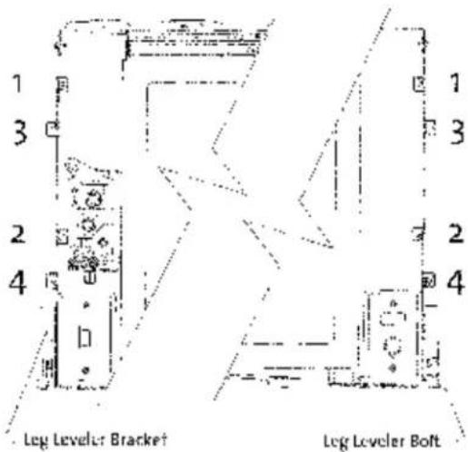
Figure 10. Surround bracket tab orientation.
Connecting the Gas Supply
Gas Supply Requirements
ALL INSTALLATIONS MUST COMPLY WITH LOCAL CODE OR IN THE ABSENCE OF LOCAL CODE, MUST COMPLY WITH THE MOST RECENT EDITION OF THE NATIONAL FUEL GAS CODE ANSI Z223.1/NFPA 54 OR CAN-B149.
THIS PRODUCT MUST BE INSTALLED BY A LICENSED MASTER OR JOURNEYMAN PLUMBER OR GAS-FITTER WHEN INSTALLED IN THE COMMONWEALTH OF MASSACHUSETTS.
Shut-off Valve
All codes require a gas Shut-off valve (gas cock) and union to be installed in the supply line and in the same room as the appliance. This allows for the disconnection of the fireplace for servicing and maintenance. See Fig. 11.
A T-HANDLE GAS SHUT-OFF VALVE IS REQUIRED IN MASSACHUSETTS IN COMPLIANCE WITH CODE 248CMR.
The fireplace and gas control valve must be disconnected from the gas supply piping during any pressure testing of the system at test pressures in excess of 1/2 psig. For pressures lowe. than 1/2 psig, isolate the gas supply by closing the manual shut-off valve.
Control Valve Connection
As mounted, the gas supply line connection is made to the upper end of the valve. The gas supply line should be a minimum 3/8" diameter, or the appropriate size to provide sufficient gas pressure to the valve regardless of the input setting.
The use of flexible gas appliance connectors is acceptable in many areas in the U.S. In Canada, methods vary depending on local code. If local codes permit, use flexible gas line for ease of installation and service. For those locales where flexible gas lines are not permitted, use the 3/8" Iron fitting to make the connection at the top side of the Control Valve. See fig. 11.
Secure all joints tightly using appropriate tools and sealing compounds (for propane units, be sure to use compounds that are propane resistant). Turn on gas supply and test for gas leaks using a 50/50 soapy water solution or a gas detector. Never use an open flame to check for leaks.
Soap Solution Leak Test
• Mix a 50-50 solution of water and dish soap.
- Light appliance- see lighting instructions on page 23 of this manual or on the fireplace's rating plate.
- Brush or spray all joints and connections with the soapy water solution.
- If bubbles appear at any connection or seam or a gas odor is detected, immediately turn gas control knob to the OFF position.
Tighten or 'econnect the leaking joint and retest for any gas leaks.

Figure n. Gas supply line fittings.
Gas Pressure
Proper gas pressure provides a consistent flow of gas to the appliance and is instrumental in checking for gas leaks. The gas control valve on the fireplace is equipped with pressure test points for gauge connections. The gauge connections are located on the front of the valve next to the On/Off/Pilot knob. Gauge connections are identified by:
E
A
• IN / E for inlet or supply pressure (the amount of gas coming to the valve.)
- OUT / A for manifold pressure (the amount of gas that is coming out of the valve to the burer.)
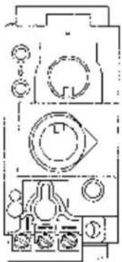
Figure 12. Pressure test points located on the front of the valve.
The appliance must be isolated from the gas supply line by closing its individual manual gas shut-off valve (gas cock) during any pressure testing of the gas supply piping system that is equal to or exceeds pressures of 1/2 psig (3.5 kPa).


ALWAYS TEST PRESSURE WITH VALVE CONTROL KNOB SET ON HIGH. Symptoms of incorrect gas pressure include:
Insufficient gas pressure:
- Small pilot flame which can result in insufficient millivolts.
- Little variation in flame picture between Hi and 10 settings.
- Insufficient gas to support more than one appliance causing nuisance outages or gas surges.
Excessive gas pressure:
- Permanent damage to valve causing complete appliance shut down.
- Too large a pilot flame resulting in overheating of the power generator and consequent snut down.
- Sooting due to impingement and/or incorrect fuel to air mix.
High Altitude Adjustment
Installations located at altitudes from 2000 - 4250 ft. (610 M - 1370 M) require adjustment for differences in pressure. Use letul High Altitude Adjustment Kit 156453 for propane or 156452 for natural gas adjustment.
Fuel Conversion
The Jotul Ct 550 Fireplace is designed to for use with either Natural gas or Propane. It is shipped from the factory configured to use Natural gas. A conversion kit is included for conversion to Propane use if desired. Check the identification label on the Control Valve to confirm that the correct fuel is used.
WARNING:
THE CONVERSION KIT IS TO BE INSTALLED BY AN AUTHORIZED J∅TUL SERVICE TECHNICIAN IN ACCORDANCE WITH THE MANUFACTURER'S INSTRUCTION AND ALL CODES AND REQUIREMENTS OF THE AUTHORITY HAVING JURISDICTION. FAILURE TO FOLLOW THESE INSTRUCTIONS COULD RESULT IN SERIOUS INJURY OR PROPERTY DAMAGE. THE QUALIFIED AGENCY PERFORMING THIS WORK ASSUMES RESPONSIBILITY FOR THIS CONVERSION.
IN CANADA:
THE CONVERSION SHALL BE CARRIED OUT IN ACCORDANCE WITH THE REQUIREMENTS OF THE PROVINCIAL AUTHORITIES HAVING JURISDICTION AND IN ACCORDANCE WITH THE REQUIREMENTS OF THE CAN1-B149.1 AND .2 INSTALLATION CODE.
Figure 13. Firebox component identification.
Conversion Kit Contents:
#156446 - LP #156447 - NG
• 1 Regulator Tower labeled for Propane
• 3 Regulator Tower Screws
• t Burger Orifice (#31 NG, 1.80 mm LP)
• Pilot Orifice (#30 for LF, #51 for NG)
- Label A - to be completed and applied to the control valve.
- Label B - apply to Live Fireplace Rating Plate as designated on the plate.
Tools required:
- 1/2" or 13 mm deep well socket and wrench
- Iorx 1-20 or small spade screwdriver
- 4 mm hex key, included in kit
CAUTION: Before proceeding with the gas conversion, the gas supply must be shut off prior to disconnecting electrical power.
Fuel Conversion Procedure
- Remove the Burner assembly:
- If you have not already done so, remove the fettle and log set from the firebox. CAUTION: THE LOGS ARE FRAGILE. Handle them with care and set aside out of the way. See fig. 13.
- Remove the Burner Skirt attached to the rear of the firebox by two sheet metal screws.
-
Loosen the wingnut on the Air Shutter Stem, located under the center of the firebox floor, and push the stem as far as it will go toward the back of the insert. Disengage the burner assembly from the Air Shutter by lifting it up and back, out of the firebox. Swing the Air Shutter out of the way to access the burner orifice. Fig. 14.
-
Change the Burner Orifice:
- Using a 13 mm deep well socket, remove the burner orifice and replace with the appropriate orifice, supplied in the kit. Tighten securely.
-
Change the Air Shutter position: Lift the Air Shutter tube up in its slots to turn the tube over, so that the appropriate fuel type indicator (LP or NG) is oriented facing you. See fig.15.
-
Change the Pilot Orifice:
- Disengage the Pilot Hood by releasing the retainer clip as shown in Fig. 16. Using a 4 mm hex key, unscrew the pilot orifice (counterclockwise). Replace with the orifice from the kit. Tighten new orifice securely into the base of the pilot assembly.
- Replace Pilot Hood by pushing it into the base.
-
Replace the Burner Assembly: Slide the venturi tube into the Air Shutter and engage the tube fully over the orifice. The burner should engage with the support brackets on the floor of the firebox. Properly located, the burner will be level and locked into correct alignment with the pilot assembly as in fig. 13.
-
Adjust the Air Shutter:
- Slide the shutter forward (toward yourself) to open the inlet. Slide it back to live rear to close. The shutter is set at the half way position at the factory. This is an optimum setting for most installations using natural gas. Propane use, however, may require a different setting.. See the section, Flame Appearance / Air Shutter Adjustment on page 22 for further details.
- Change the Regulator: See Fig. 7
- Using a Torx T-20 screwdriver or small spade screwdriver, remove the three specialty screws from the front of the valve regulator.
- Remove the regulator tower and gasket. BE SURE TO REMOVE THE BLACK RUBBER GASKET FROM THE VALVE.
• Install the new variable regulator lower with the new rubber gasket. I thoroughly tighten new regulator to valve body.
- Apply the Conversion Labels:
- Apply LABE: A to the cabinet floor so that it may be seen by anyone servicing the fireplace. - Apply LABE: 3 to the Rating Plate in the space provided.
- Reassemble the fireplace, apply gas to the system and check for gas leaks 'including all gas lines before and after the valve, NEVER USE AN OPEN FLAME TO CHECK FOR GAS LEAKS.
Use an electronic gas detector or 50/50 soapy water solution to check for leaks at all connection joints. The soap solution will actively bubble if a leak is present. Tighten connections until no leaks are detected.
IMPORTANT: Correct gas pressure is essential for efficient and safe operation. It is important that the correct gas pressure be established at the time of the installation. For more details, see the Gas Pressure section of this manual on page 15 and the Rating Plate.
WHEN LIGHTING THIS APPLIANCE, ALWAYS REFER TO THE LIGHTING INSTRUCTIONS ON THE INSIDE BACK COVER OF THIS MANUAL.

Figure 14. Mail: onifice location with burner skirt and burner assembly removed.

Figure 15. Changing the Air Shutter orientation.

Figure 16. Pilot Crifice replacement.

CAUTION: LABEL ALL WIRES PRIOR TO DISCONNECTION WHEN SERVICING THE CONTROLS. WIRING ERRORS CAN CAUSE IMPROPER AND DANGEROUS OPERATION. ALWAYS VERIFY PROPER OPERATION AFTER SERVICING THE APPLIANCE. ATTENTION: AU MOMENT DE L'ENTRETIENDES COMMANDES, ETIQUETEZ TOUS LES FILS AVANT LE DEBRANCHEMENT. DES ERREURS DE CABLAGE PEUVENT ENTRAIUN FONCTIONNEMENT INADEQUAT ET DAGEREUX.
Wall Thermostat Installation
Use Wall Thermostat #750003, or a 750 millivolt DC two-wire circuit thermostat, to automatically control your fireplace operation. The thermostat should be placed in the same room as the heater, typically 5' off the floor. Avoid drafty areas of any area that may effect the accuracy of the thermostat.
The thermostat should be connected to the insert using a minimum 16 gauge wire with a maximum length of 35 feet of wire.
- Remove the burner switch box to access the wire harness. Connect one of the thermostat leads to the orange pigtail lead extending from the wire harness.
- Connect the other thermostat lead to the 1H terminal on the valve. DO NOT DISCONNECT ANY WIRES. See fig. 18.
At the wall thermostat, the two wires should be connected to the two connection terminals on the thermostat base plate per the manufacturer's instructions.
For thermostatic function, place the rocker: switch in the T-STAT position. The pilot flame must be lit.

Figure 18. Wimmy Diagram for optional thermostat.
Remote Control
The optional Jetul Remote Control 129706 may be installed in place of the factory-installed manual Burner switch.
- Remove the switch box from the valve compartment. Remove the switch plate and disconnect the wires from the TH and TH/TP terminals under the valve.
- Install the Receiver switch/battery box assembly supplied with the remote control or to the front of the insert burner switch box. Attach the Receiver cover plate. See Appendix A, page 2B, for additional details.
3 Run the wires out the back of the switch box and connect the leads to the TH and TH/TP terminals on the valve. DO NOT DISCONNECT ANY WIRE FROM THE VALVE. - Re-install the switch box to the valve compartment floor using the same nut previously removed.
Blower Power Requirement
The blower is fully assembled and requires no adjustment.
Run the 10 ft. power cord out forward from the fire-place to the nearest grounded power outlet
The blower must be electrically grounded in accordance with local codes or, in the absence of local codes, with the current NFPA 70- National Electrical Code or CSA C22.1-Canadian Code.
A three-prong (grounding) power supply plug is included for protection against shock hazard and should be plugged directly into a properly grounded three-prong receptacle. DO NOT CUT OR REMOVE THE GROUNDING PRONG FROM THE PLUG.
■ ALWAYS DISCONNECT THE POWER SUPPLY BEFORE SERVICING THE BLOWER.

Figure 19. Blower Wiring Diagram
Optional Brick Panel Kit Assembly
CAUTION: THESE PANELS ARE EXTREMELY FRAGILE! SUPPORT EACH PIECH WITH BOTH HANDS AND HANDLE TENDERLY.
Install the optional Brick Panel Kits before installing the log set. No fasteners or tools are required. Brick panels are shown here, however, Corrugated panels install in the same way. Both style panels are reversible.

Figure 20. Align the Rear panel mortar joints with those in the side panels.
- Remove the Glass Frame, if you have not already done so. See fig. 1, pg. 3.
- Remove the Log Set. These parts are not fastened. Simply lift them out of the firebox.
- Install the Rear Panel. Orient the rear panel to align with the brick courses on the Side Panels as shown in fig. 20. Place the panel against the back wall of the firebox, resting on the log shelf as in fig. 21.
- Install the Side Panels. Orient the panel straight upright, with the leading edge on the support shelf, as shown in fig. 22a. Slide the pane. All the way back, keeping it sandwiched between the side wall and the end of the air deflector. See fig. 22b.
- Replace the Log Set, and Glass Assembly.

Figure 21. Install Rear Panel.

Figure 22a. Install Side Panel vertically.

Figure 22b. install the Side Panels taking care to clear the Air Deflector.
Log Set Assembly
Much time and effort has been devoted to attaining a lively, realistic flame picture while simultaneously achieving efficient fuel combustion and effective heat output under a variety of installation conditions. The flame picture you experience, however, will be affected by a number of variables peculiar to your installation such as venting configuration, environmental and weather conditions, and fuel type. Log placement is critical to the final flame picture. Pay particular attention to placing the log pieces as illustrated here. Carefully unpack and arrange the logs as outlined below. CAUTION: The logs are fragile. Please handle each piece with care.
Use safety gloves to handle the log parts as the ceramic fibers can initiate skin.
- Place the Rear Log on the burner skirt against the back of the firebox as shown in fig. 24.
- Set the Lower Left and Right logs in place on the burner plate pegs as shown in fig. 25.
- Set the three upper logs on the appropriate pegs as shown in fig. 26.
- Lightly scatter the Ember Stones, included in the Log Set package, over the burner plate. Place them directly on top of the burner base and around the log parts. DO NOT ALLOW EMBER STONES TO BLOCK THE PILOT ASSEMBLY AREA. The burner ports directly in front of the pilot must remain clear for proper burner ignition.
- Rep ace the Glass Panel Frame using the Latch Release tool to engage the latches with the frame. See fig. 1, page 3.

Figure 23. CI 550 DV Log Set 156450.

Figure 24 Place the rear log against the back wall.
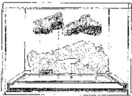
Figure 25. Place the base logs on the burner pegs.

Figure 26. Locate the upper lags on the appropriate pegs.
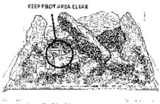
Figure 27. Assembled log set and embers.
System Check
-
PURGING THE GAS LINE: When lighting the appliance for the first time it will take a few moments to clear the gas line of air. Once this purge is complete, the appliance will operate as described in the lighting instructions located on the fireplace's rating plate and back cover of this manual.
-
PILOT FLAME: The pilot flame should be steady, not lifting or floating. The flame should be blue in color around the pilot hood, with traces of yellow toward the outer edges. It is imperative that the pilot flame engulf the top 3/8" of the thermopile (power generator) and the top 1/8" of the quick drop-out thermocouple. The pilot flame should project out of the pilot hood 1" at all three ports, extending to reach the burner plate ports. See fig. 28.
Pilot Shutter Adjustment
The Pilot Stutter, located directly behind the pilot assembly, is set fully-open at the factory. Those installations which include a long, external vent run may be susceptible to draft conditions that can affect pilot stability and cause the valve to shut off automatically. In such cases, adjusting the shutter to a closed, or partially-closed position, will help improve pilot stability.
- BURNER ADJUSTMENT: Your gas fireplace is equipped with a variable gas control valve. This valve provides easy adjustment of the flame height appearance and heat output. To adjust the flame between the HI and LO setting, rotate the HI/LO knob, located in the center of the valve face. Flame height will adjust approximately 50% between the HI and LO settings
NO SMOKE OR SOOT SHOULD BE PRESENT. CHECK LOG PLACEMENT IF ANY SOOT OR SMOKE IS APPAR-ENT. IF SOOT OR SMOKE PERSISTS, THE AIR SHUTTER MAY NEED TO BE ADJUSTED.
CAUTION:
DO NOT ATTEMPT TO ALTER THE FLAME APPEARANCE BY PLACING THE GAS CONTROL IN ANY POSITION OTHER THAN THE FULL "ON" POSITION.
Flame Appearance / Air Shutter Adjustment
THIS FIREPLACE IS SHIPPED FROM THE FACTORY EQUIPPED TO USE NATURAL GAS. IF THE BURNER HAS BEEN CONVERTED FOR USE WITH PROPANE, IT MAY BE NECESSARY TO ADJUST THE AIR SHUTTER TO ACHIEVE AN IDEAL AIR-TO-GAS RATIO. See page 22.
WARNING:
AIR SHUTTER ADJUSTMENTS SHOULD ONLY BE PER- FORMED BY A QUALIFIED, PROFESSIONAL SERVICE TECHNICIAN.
The air shutter adjustment can also help achieve the desired flame appearance. Generally, flame appearance is a matter of indiv dua: preference, however a warm yellowish flame is most common.
Closing the air shutter - in extreme cases may generate very long yellow flames resulting in soot. Sooting produces black deposits on the logs, on the inside walls of the appliance, and potentially on the exterior termination cap. Sooting is caused by incomplete combustion in the flames and lack of combustion air entering the air shutter opening.
Opening the air shutter - will generate a flame that is blue and transparent, or "anemic". This flame is generally more efficient, but not as attractive.
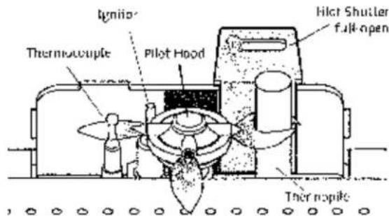
Figure 28. Correct Pilot flame pattern and Pilot Shutter location.

Figure 29. Correct flame pattern at maximum output. Adjust the air shutter if necessary to achieve desired flame pattern.
Air Shutter Adjustment
The Air Shutter is set half-open at the factory. This setting provides good combustion characteristics with either natural gas or propane in a variety of operating conditions. You may find, however, that your particular installation requires adjustment to allow for a greater or reduced air/fuel ratio. Follow this procedure to adjust the air shutter setting.
- Locate the Air Shutter adjustment stem extending down from the center of the firebox floor. You will not be able to see it, however, you will be able to feel it about 3 inches from the front of the glass frame. See fig. 29.
- Loosen the wing nut and pull the stem forward to open the air inlet to allow more air into the burner. Push it to the rear to reduce the air. Make adjustments in 1/8" (3 mm) increments.
Between adjustments, allow the fire to burn 15-20 minutes on the HIGH selling, observing the flame continuously.
- If the flames are azy, or sooty, move the shutter forward to increase oxygen. If the flame appears weak, jet-like, or blue, move the shutter back to decrease air. Repeat the process until the flame is as desired. Retighten the wing nut.
Surround Assembly
Each of the surround assemblies and front facings is completely assembled at the factory. No further assembly is required. All assemblies utilize hooved brackets (fig. 30) that simply hang onto the inboard tabs on the fireplace cabinet as shown in fig. 70 on page 14.
- Be certain the blower power cord is routed to the front of the insert.
- Hang the Wide Surround first, if appropriate, on the outboard tabs on the firebox assembly.
- Cast Iron Surround: Remove the upper deflector. See fig. 8, page 13. Lift the surround assembly by the upper panel to engage the hooks with: The Inboard fanger tabs on the firebox assembly.
- Steel Facings: Open the doors and lift the assembly by the upper panel to engage the hanger bracket hooks with the inboard hanger tabs.
Plinth
A plinth panel is incorporated into the Cast Iron Sur- rounds. If you choose not to use it, the panel can be removed simply by bending the panel back and forth to snap it off of the surround backing plate.
Rating Plate Location
The Lighting Instructions / Rating Plate is tethered to the Valve & Burner controls compartment on the left side of the fireplace insert. Simply pull it out to reference when operating the fireplace.
Cast Iron Surround Only: If you are installing a cast iron surround, relocate the rating plate underneath the firebox floor where it will be readily accessible after the surround is hung in place.

Figure 3c. All surround panels incorporate hanger brackets that engage with the hanger tabs on the firebox.
Operation
- Your fireplace can be operated manually using the On/Off/T-stal rocker switch or it can be automatically controlled using an optional wall-mounted thermostat or remote control device. A separate switch is provided for the built-in forced air blower. Familiarize yourself with the location and function of the controls. Gas Valve and Burner controls are located in the left compartment. Blower controls are in the right hand compartment. See figs. 31 - 34. Piezo Ignitor - Push button pilot light ignition.
Gas Control - Used to control the pilot light and gas flow from the supply line.
Regulator - Allows you to adjust heat output and flame intensity from maximum down to 50%.
ON/OFF/T'STAT Switch - Allows for manual or thermostatic control of the barrier.
Always follow the Lighting Instructions located on the inside Back Cover of this manual and also on the Rating Plate, located in the burner controls compartment.
-
For the first several hours of operation, it is common to detect some odor as the metal and manufacturing materials cure under heat. This condition is temporary and can be alleviated by allowing plenty of fresh air to circulate through the area.
-
Condensation may develop on the glass upon each lighting of the appliance. This "fog" will disappear as the glass heats.
-
Keep the controls and the area under the appliance free of debris; vacuum L this area frequently, especially if you have pets. Always keep the appliance area clear and free from combustible materials, gasoline and other flammable liquids.
When a vacuum is used on any service for the fireplace. ALWAYS be sure the fireplace is completely cold.
-
This fireplace utilizes a continuously burning pilot flame. Exercise caution when using household products containing combustible vapors.
-
CAUTION: DO NOT OPERATE THIS APPLIANCE WITH THE CLASS REMOVED, CRACKED OR BROKEN. REPLACEMENT OF THE CLASS SHOULD BE DONE BY A LICENSED OR QUALIFIED SERVICE PERSON. USE ONLY REPLACEMENT GLASS PROVIDED BY YOUR AUTHORIZED J∅TUL DEALER. NEVER USE ANY SUBSTITUTIVE MATERIALS.

Figure 31. The pilot assembly is located on the left side, under the rear log.
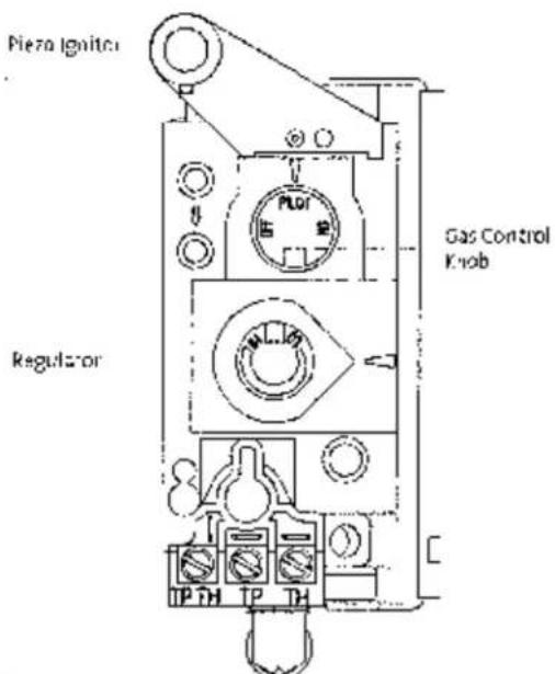
Figure 32. GI 550 DV Gas Valve and Regulator.
WARNING:
OBSERVE CAUTION NEAR THE GLASS PANEL. THE GLASS MAY SHATTER IF STRUCK BY AN OBJECT. ALWAYS HANDLE THE GLASS PANEL WITH CARE.
Figure 33.
GI 550
DV Burner
Control
Switch.

Figure 34.
Glssu DV and
Blower Controls.
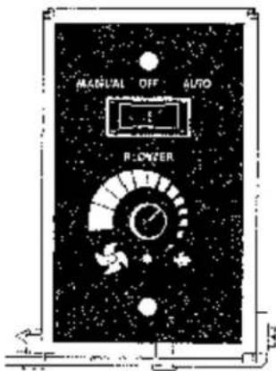
Blower Function
The blower's controlled by a heat-activated switch (snapstat) that will only function if the blower control switch is in either Live Manual or Automatic setting. In the Automatic setting, the blower will not operate until the sensor reaches 120°F. This will take about 10 minutes in most installations.
Converse y. once the burner is off, the blower will continue to operate until the snapstat cools down to no°F and shuts off power to the blower.
If the blower is not needed, place the blower control switch in the OFF position and the snapstat will not function.
CAUTION: ALWAYS DISCONNECT THE BLOWER UNIT FROM THE POWER SUPPLY WHEN PERFORMING ANY MAINTENANCE.
Maintenance
The GI 550 DV gas fireplace and its venting system should be inspected before use and at least annually by a qualified service technician.
IMPORTANT:
ALWAYS TURN OFF THE GAS SUPPLY TO THE FIREPLACE AND UNPLUG THE FORCED AIR BLOWER BEFORE ANY SERVICE WORK IS PERFORMED ON THE FIREPLACE.
Annual Cleaning
Vent System
The entire vent system, including the chimney, should be inspected and cleaned every year. If the intake and exhaust venting is disassembled for any reason, it should be reassembled and sealed according to the vent manufacturer's instructions provided at the initial installation.
Burner and Log Set
Periodically inspect: the Firebox, Valve Compartment, Blower Assembly and Convection Airways to BE CERTAIN THAT THE FLOW OF COMBUSTION AND VENTILATION AIR IS UNOBSTRUCTED.
The firebox should be vacuumed at least annually to remove any surface build up. Use a soft brush attachment and handle the logs carefully as they are fragile. Be sure to vacuum or wipe off the pilot assembly, burner orifice and burner tube.
Glass Care
Clean the glass as necessary. Wipe the surface with a clean, dampened, soft cloth. Follow with a dry, soft towel. Take care not to scratch the glass surface.
Scan 70i: Sliding Glass Panel Care
The black coating around the perimeter of the back of this glass is especially prone to fingerprinting when handled. Fingerprints may be wised clean with a soft cloth and any common window cleaning solution.
WARNING: DO NOT USE ABRASIVE CLEANERS ON THE GLASS. NEVER CLEAN THE GLASS WHEN IT IS HOT.
Gasket Inspection
It is important that the glass gasket be inspected at least annually. Examine the ribbon gasket for signs of deterioration and make sure the gasket has a positive seal. Replace the gasket if necessary. Refer to the replacement part's list on page 27.
Glass Panel or Gasket Removal
- Use the Latch Release Tool to disengage the latches from the glass frame. See Fig 1, pg. 3
- Swing the bottom of the glass frame out and lift to disengage it from the retaining lip at the top of the firebox, say the assembly on a flat surface, protecting the frame from scratches using a blanket or towel.
- The glass panel is held in place by four retainer clips. Use a screwdriver to carefully pry these up off the edge of the glass retaining walls. See fig. 35.
- Remove the old gasket material.
Glass Panel or Gasket Replacement
- Wrap the new gasket material evenly around the edge of the glass, peeling back the protective strip to expose the adhesive as you go. Press the adhesive side down onto the glass surface. Do not stretch the gasket. See fig. 36.
- Place the gasketed glass within the frame and press each of the retainer clips back into place on the retainer walls.
FOR REPLACEMENT, USE ONLY J∅TUL CERAMIC GLASS PANEL PART 156438. DO NOT USE ANY OTHER TYPE OF GLASS WITH THIS APPLIANCE.

Figure 35. Glass Retainer Clip locations.

Figure 36. Gasket Replacement

Figure 37. Part identification.
Universal CI 550 DV Part List
| No. | Description | Part Number |
| 1. | Screw, Pan Head 10-32 x 3/8 | 177911 |
| 2. | Wall, Inner Back | 221578 |
| 4. | Burner Skirt, Rear | 222210 |
| 5. | Cabinet Wall, Rear | 221398 |
| 6. | Bracket, Blower Mounting | 222414 |
| 7. | Blower TransFlow 122 CFM Replacement | 156455 |
| 8. | Heat Shield, Left | 221736 |
| 9. | Cabinet Wall, Left | 221397 |
| 10. | Wingnut, M6 | 177975 |
| 11. | Control Box Receptable | 221048 |
| 12. | Wire Strain Relief Heyco | 17851 |
| 13. | Switch, On/Off/T/Sut, Plain | 220703 |
| 14. | Rheostal, Long Lead >6" | 220970 |
| 15. | Cover Plate, Blower Switch Flow | 221394 |
| 16. | Rheostat Control Knob | 220709 |
| 17. | Air Deflector, Cabinet Top | 2225692 |
| 18. | Burner Switch Cover Place, S Ikscreened | 222272 |
| 19. | Ignitor Bracket | 3907576 |
| 20. | Screw, M4 x B PH Pan Head | 17920 |
| 21. | Piezo Ignitor Button | 3902573 |
| 22. | Valve, NG, High Torop, 50% TD | 222263 |
| 23. | Elbow, 90° Brass 3/8 NTP | 222297 |
| 24. | Latch Assembly | 221712 |
| 25. | Cabinet Base | 221584 |
| 40. | Leg Leveler Bracket, Rig | 222420 |
| Leg Leveler Bracket, Lef. | 222730 | |
| 21. | Solt, Leveling, M8 x 42 | 118047 |
| 28. | Nut, Flex, Plain M6 DIN 934 | 99320 |
| 29. | Screw, Pan Lead 10-32 x 3/8 | 17911 |
| 30. | Firebox Weldment | 221574 |
| 31. | Valve Bracket | 221885 |
| 32. | Screw, #8 x 3/4" | 179886 |
| 35. | Pilot Assembly | 129477 |
| 34. | Pilot Spacer | 222284 |
| 35. | Casket, Pilot Assembly | 129670 |
| 36. | Pilot Access Panel | 221399 |
| 37. | Gasket, Pilot Access Panel | 129153 |
| 38. | Vent Installation Tool | 222267 |
| 39. | Vent Pipe Adapter | 222205 |
| 40. | Cabinet Top | 221757 |
| 41. | Casket, Vent Adaptor | 222281 |
| 42. | Vent Connector Assembly | 222759 |
| 43. | Casket, 3" Adaptor | 129677 |
| 44. | Heat Shield, Top Firebox | 222415 |
| 45. | Rel e" Door | 222432 |
| 46. | Burner Top Plate | 221749 |
| 47. | Burner Air Defector | 222059 |
| 48. | Nut, Hex, Plair M6 DIN 934 | 9930 |
| 49. | Burner Gasket | 222283 |
| 50. | Bolt, M6 x 20 Srrc Farge Hex Hd | 17117 |
| 51. | Burner Base | 104762 |
| 52. | Ventur Tube | 221301 |
| 53. | Tube Holder | 103097 |
| 54. | Nut, M6 Scr. Flange | 117068 |
| No. | Description | Part Number |
| 40-54 | Burner Assembly, Replacement | 156454 |
| 55. | Primary Air Shutter | 221350 |
| 56. | Handle, Primary Air | 227389 |
| 57. | Gasket, 2.25 in. OD, x .125 in. | 220734 |
| 58. | Fender Washer, .350 in. x 2.250 in. | 118023 |
| 59. | Fettle, Blue Black Ensmel | 10432737 |
| 60. | Heat Shield, Right | 227051 |
| 61. | Capinee Wall, Right | 227971 |
| 62. | Snapstal, 120-no°F | 220617 |
| 63. | Snapstal Bracket | 220984 |
| 64. | Class Frame Handle | 222268 |
| 65. | Orifice, 4:1 - NG | 045026 |
| 66. | Casket, Drop-in, Orifice Holdz | 222280 |
| 67. | Orifice Holder, Drop-in Assembly | 222291 |
| 68. | Tinnerman U-Clip | 220042 |
| 69. | Glass Gasket, .250 x 1" No mole Hberglass | 129154 |
| 70. | Glass, Ceramic / 5 mm | 22778 |
| 68-70 | Replacement Glass Kit | 156438 |
| 71. | Replacement Class Frame, Matte, Black Replacement Glass-frame Jatul Iron | 156021 |
| '56790 | ||
| 72. | Log Sel, 6 pcs. Illustrated on pg. 30. | 156450 |
| 73. | Blower Kit* | 156455 |
| 74. | kheostat K"* | 156456 |
| 75. | Blower Switch Box Kit, complete | 156459 |
| 76. | Vent Adaptor Assembly, inc. gaskets | 156464 |
| 77. | Pilot Shutter | 222498 |
- Eaffle
* not illustrated
| Use only genuine IoTul Replacement Parts available from your local Authorized IoTul Dealers or by contact ing: |
| Iptul North, America35 Hutcherson Dr.Gouhain, ME 04038 |
| 207591-0601 |
Appendix A
Remote Control Installation
The optional Jocul Remote Control 129706 may be installed in place of the factory-installed manual burner switch. Follow this procedure:
: Remove the Burner Switch Box from the valve compartment. Remove the switch cover plate and disconnect the wires from the TH and TH/TP terminals under the valve.
2. Remove the Receiver from the plastic Fireplace Mounting Plate.
a) Pry off the slide switch cap.
b) Press down, then release the battery box to disengage it from the receiver box.
c) Slide the receiver box out from the plastic fireplace mounting plate. See fig. 38.
d) Replace the battery box into the receiver.
- With the battery box oriented to the right, attach the Receiver assembly onto the front of the insert Burner switch box using the two sheet metal screws previously removed from the original coverplate. See fig. 59.
4 Attach the Receiver Cover plate to the Receiver using the two small screws supplied in the kit. Replace the battery box and slide switch cap. Place the switch in the OFF position. - Run the receiver wires cut the back of the switch box and connect the leads to the TH and TH/TP terminals on the valve. DO NOT DISCONNECT ANY WIRES FROM THE VALVE.
- Reinstall the switch box to the valve compartment floor using the same nut previously removed.
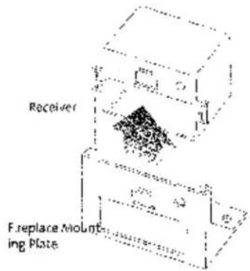
Figure 38. Remove the Receiver from the fireplace mounting plate.

Figure 39. Install Remote Receiver into the burner switch box.
Approved Vent Manufacturers
The Jøtul GI 550 DV fireplace insert is approved for installation with direct vent chimney components supplied by the following manufacturers:
Simpson Dura-Vent, Inc.
P.C. Box:570
Varaville, CA 95696-1510 800-835-4479
Selkirk Corporation
1307 W. President George Bush Hwy, Suite 330
Richardson, TX 75080-1139 800-952-8368
American Metal Products (Amerivent)
8601 Hacks Cross Rd.
Olive Branch, MS 38654 800-423-4270
Security Chimneys International Limited 2125 Monterey, Laval, Québec
Canada, H7L3T6 450-973-9999
Metal-Fab, Inc.
P.O. Box 113B
Wichita, KS 67201 315-943-2351
Industrial Chimney Corp.
Excel Direct Vent
400 J-F Kennedy
Sl. Jctoine, (Quebec)
Canada, J7Y 4B7 450-565-6336
Jøtul Group Gas Product Limited Warranty
This warranty policy applies to gas products identified by Iptul, Scan, and Atra trade names, as set forth below.
A. Cast Iron, Steel Doors, Surround Components, Firebox:
Jøtul North America Inc. (J∅TUL) warrants, to the original retail purchaser, that those components of the Jøtul, Scan, or Atra Gas Stove or Fireplace specified above will be free of defects in material and workmanship for a period of five (5) years from the date of purchase. This warranty is subject to the terms, exclusions and limitations set forth in the following text.
B. Burner, Burner Treatments, Firebox Panels:
J∅TUL warrants, to the original retail purchaser, that those components of the Jøtul, Scan, or Atra Gas Stove or Fireplace specified above will be free of defects in material and workmanship for a period of two (2) years from the date of purchase. This warranty is subject to the terms, exclusions, and limitations set forth in the following text
C. Gas & Electrical Components (controls, plumbing, valve, blower):
J∅TUL warrants, to the original retail purchaser, that those components of the Jøtul, Scan, or Atra Gas Stove or Fireplace specified above will be free of defects in material and workmanship for a period of one (1) year from the date of purchase. This warranty is subject to the terms, exclusions, and limitations set forth in the following text.
JQTUL will repair or replace (including parts & labor), at its option, any of the above components determined by JQTUL to be covered by this warranty. You must, at your own expense, arrange to deliver or ship the component to an authorized Jptul, Scan, or Atra dealer and arrange for pickup or delivery of the component after repairs have been made. If, upon inspection, JQTUL determines that the component is covered by this warranty, the repair or replacement will be made as set forth above. This warranty is not transferable and is extended only to, and is solely for the benefit of, the original retail purchaser of the Jptul, Scan, or Atra Gas Stove or Fireplace. This paragraph sets forth the sole remedy available under this warranty in the event of any defect in the Jptul, Scan, or Atra Gas Stove or Fireplace.
The warranty period for any replaced component will be the remaining unexpired portion of the warranty period for the original component
Please retain your dated sales receipt in your records as proof of purchase. EXCLUSIONS AND LIMITATIONS
NOTICE: This warranty is void if installation or service is performed by someone other than an authorized installer, service agency or gas suppliers; or if installation is not in conformance with the installation and operating instructions contained in this owner's manual or local and/or national fire and building regulations. A listing of local authorized installers, service agencies and gas suppliers can be obtained from the National Fireplace Institute at http://www.nificertified.org/.
This warranty does not cover the following:
1) Repair or replacement of parts that are subject to normal wear and tear during the warranty period or to parts that may require replacement in connection with normal maintenance. These parts include gaskets and glass (except to the extent such parts suffer damage from thermal stress).
2) Damage due to incorrect installations not in conformance with the installation instructions contained in this owner's manual or local and/or national fire and building regulations.
138727_Rev_E 4/26/17
3 Damage due to service performed by an installer, service agency or gas supplier, unless otherwise agreed to in writing by J∅TUE.
4) Labor or other costs associated with the repair of gas controls, plumbing, burners, log sel, or sheet metal firebox beyond the warranty period.
5) Damage caused by unauthorized modification, use or repair.
6) Damage to enameled surfaces caused by improper operation or misuse, including use that is not in conformance with the operating instructions contained in this owner's manual. Such damage can typically be identified by bubbling, cracking, or discoloration of the enamel finish.
7) Costs incurred by travel time and/or loss of service
8) Damage incurred while the Jatul, Scan, or Africa Gas Stove or Fireplace is in transit.
IN NO EVENT SHALL JOTUL, ITS PARENT COMPANY, SHAREHOLDERS, AFFILIATES, OFFICERS, EMPLOYEES, AGENTS OR REPRESENTATIVES BE LIABLE OR RESPONSIBLE TO YOU FOR ANY SPECIAL INDIRECT, INCIDENTAL, CONSEQUENTIAL, PUNITIVE OR OTHER SIMILAR DAMAGES, INCLUDING, BUT NOT LIMITED TO, LOST PROFITS, LOST SALES, INJURY TO PERSON OR PROPERTY, OR DAMAGES TO A STRUCTURE OR ITS CONTENTS, ARISING UNDER ANY THEORY OF LAW WHATSOEVER. ALL IMPLIED WARRANTIES, INCLUDING THE IMPLIED WARRANTIES OF MERCHANTABILITY AND FITNESS FOR A PARTICULAR PURPOSE, OR OTHERWISE, ARE LIMITED IN DURATION TO THE LENGTH OF THIS WRITTEN WARRANTY. EXCEPT AS EXPRESSLY SET FORTH HERFIN, JOTUL MAKES NO ORAL, WRITTEN OR OTHER WARRANTY WITH RESPECT TO JOTUL, SCAN OR ATRA GAS STOVES OR FIREPLACES.
Some states do not allow the exclusion or limitation of incidental or consequential damages, or limitations on the length of implied warranties. Therefore, the above exclusions or limitations may not apply to you. This warranty gives you specific legal rights, and you may have other rights, which vary from state to state.
JOTUL reserves the right to discontinue, modify or change the materials used to produce the Jetul, Scan, or Atra Gas Stove or Fireplace. JOTUL shall have the right to replace any defective component with substitute components determined by JOTUL to be of substantially equal quality and price.
The dollar value of J∅TUL's liability for breach of this warranty shall be limited exclusively to the cost of furnishing a replacement component. J∅TUL shall not in any event be liable for the cost of labor expended by others in connection with any defective component. Any costs or expenses beyond those expressly assumed by J∅TUL under the terms of this warranty shall be the sole responsibility of the owner(s) of the Jptul, Scan, or Altra Gas Stove or Fireplace.
No dealer, distributor, or other person is authorized to modify, augment, or extend this limited warranty on behalf of J∅TUL. NO MODIFICATION OR CHANGE TO THIS WARRANTY WILL BE EFFECTIVE UNLESS IT IS MADE IN A WRITTEN DOCUMENT MANUALLY SIGNED BY AN AUTHORIZED OFFICER OF J∅TUL.
An authorized installer may have been provided with certain information related particularly to the Jøtul, Scan, or Atra Gas Stove or Fireplace; however, no authorized installer or other person who may service the appliance is an agent of J∅TUL. No inference should be made that J∅TUL has tested, certified, or otherwise pronounced any person as qualified to install or service the appliance. J∅TUL shall not be liable or otherwise responsible for any error or omission by a person installing or servicing a Jøtul, Scan, or Atra Gas Stove or Fireplace.
If you believe your Jotul, Scan, or Atra Gas Stove or Fireplace is defective, you should contact your nearest authorized Jotul, Scan, or Atra dealer, who will process a warranty claim. IN ORDER TO QUALIFY FOR WARRANTY COVERAGE, JOTUL MUST RECEIVE NOTICE OF A POSSIBLE DEFECT WITHIN SIXTY (60) DAYS OF THE DATE THE DEFECT IS FIRST DISCOVERED, OR REASONABLY COULD HAVE BEEN DISCOVERED.
This warranty is given by Jotul North America, Inc., 55 Hutcherson Drive, Gorham, Maine 04038 USA
Your fireplace insert has a unique serial number slamped on the rating plate which is located in the valve compartment. Please record the serial number in the space below. You may also wish to attach your purchase receipt to this page for future reference.
MODEL NAME: Jøtul GI 550 DV Gas Fireplace Insert
SERIAL NUMBER:
DATE OF PURCHASE:
AUTHORIZED DEALER:
ADDRESS
PHONE: ____
INSTALLER:
FUEL TYPE.
FUEL CONVERSION: NO YES
NOTES:
SERVICE LOG:
Name of technician
Company Name ____
Date of service
Work Performed
SERVICE LOG:
Name of Technician
Company Name ____
Date of service
Work Performed
SERVICE LOG:
Name of Technician ____
Company Name ____
Date of service
Work Performed
LIGHTING INSTRUCTIONS
FOR YOUR SAFETY, READ BEFORE LIGHTING.
WARNING:
IF YOU DO NOT FOLLOW THESE INSTRUCTIONS EXACTLY, A FIRE OR EXPLOSION MAY RESULT CAUSING PROPERTY DAMAGE, PERSONAL INJURY, OR LOSS OF LIFE.
A. This appliance has a pilot which must be sit by hard. When lighting the pilot, follow these instructions exactly.
B. BEFORE LIGHTING, smell all around the appliance area for gas. Be sure to smell next to the floor because some gas is heavier than air and will settle to the floor.
WHAT TO DO IF YOU SMEL. GAS:
- Extinguish any open flame.
- Open windows.
- Do not light any appliance.
• Do not touch any electrical switches. -
Do not use any phone in your building.
• Ir immediately call your gas supplier from a neighbor's phone. -
If your gas supplier cannot be reached, call the fire department.
C. Use only your hand to push in or turn the gas control knob. Never use tools. If the knob will not push in or turn by hand, do not try to repair it. Call a qualified technician. Force or attempted repair may result in a fire or explosion.
D. Do not use this appliance if any part has been under water. Immediately call a qualified service technician to inspect the appliance and to replace any part of the control system and any gas control which has been under water.
LIGHTING INSTRUCTIONS
- STOP! Read the safety information above.
- Access the valve controls in the left side compartment.
- Turn the Burner ON/OFF switch to "OFF", or set the thermostat to the lowest setting (if used).
- Confirm that the gas supply line shut-off valve is open.
- Push in gas control knob slightly and turn clockwise to "OFF".

NOTE: Knob cannot be turned from "PILOT" to "OFF" unless the knob is pushed in slightly. Do not force
-
Wait five (5) minutes to clear out any gas. If you then smell gas, STOP! Follow "3" in the safety information above on this page. If you do not smell gas, go to the next step.
-
Push in gas control knob slightly and turn counterclockwise ▲ to "PILOT".
-
Push in control knob all the way and hold in. Immediately light the pilot by triggering the spark
ignitor (push the red button repeatedly) until pilot lights. Continue to hold the control knob in for about one minute after the pilot lights. Release knob and it should spring back. The pilot should re-

Pilot Assembly
main lit. If it goes out, repeat Steps 5 through 8.
- If knob does not return when released, stop and immediately call your service technician or gas supplier.
-
If pilot will not stay lit after several attempts, turn the control knob to OFF and call your service technician or gas supplier.
-
fum gas control knob counterclockwise ▲ to "ON".
-
Set the Burner switch to "ON" to light the burner. If using a thermostat, set Burner switch to "T-SIAI" and set the thermostat to the desired temperature.
TO TURN OFF GAS TO THE APPLIANCE:
- Turn ON/OFF switch to "OFF". The pilot will remain lit for normal service.
-
For complete shutdown, turn ON/OFF switch to "OFF".
-
Access the lower controls.
- Depress gas control knob slightly and turn clockwise to "OFF". Do not force.
April, 2011 138727-E
This appliance must be installed in conformance with local and national building regulations. Before beginning the installation, it is important that the these instructions be carefully read and understood. Jotul maintains a policy of continual product development. Consequently, products may differ in specification, color or type of accessories from those illustrated or described in various publications,
- INSTALLATION AND OPERATION INSTRUCTIONS
- SUGGESTED TOOLS FOR INSTALLATION AND SERVICE
- INSTALLATION REQUIREMENTS FOR THE COMMONWEALTH OF MASSACHUSETTS
- TABLE OF CONTENTS
- UNPACKING THE FIREPLACE
- 1C X 1/2" SHEET METAL SCREWS FOR BRACKETS, 8
- JØTUL GI 550 DV / SCAN 70I DIRECT VENT GAS FIREPLACE INSERT
- TEST STANDARDS
- SPECIFICATIONS
- INPUT RATES
- NATURAL GAS
- PROPANE
- MANIFOLD PRESSURE: MIN MAX
- ACCESSORIES
- CAST IRON SURROUNDS
- CAST IRON DOUBLE DOORS
- STEEL SURROUND KITS
- GENERAL INFORMATION
- IMPORTANT: SAVE THESE INSTRUCTIONS
- SAFETY INFORMATION
- INSTALLATION REQUIREMENTS
- LEG LEVELER BRACKET NOTE
- MINIMUM FIREPLACE REQUIREMENTS
- INSTALL LEG LEVELING BRACKETS
- CLEARANCE TO COMBUSTIBLE MATERIALS
- HEARTH REQUIREMENTS
- FIREPLACE FACING OPTIONS
- VENT GUIDELINES
- MASONRY FIREPLACES
- IMPORTANT
- IMPORTANT NOTICE
- MASONRY FIREPLACE VENT INSTALLATION
- WARNING
- PREFABRICATED FIREPLACES
- MODIFICATION STEPS
- PREFABRICATED FIREPLACE VENT INSTALLATION
- VENT CONNECTION
- WEAR SAFETY GLOVES
- FINAL POSITIONING
- BLOWER POWER CORD
- LEVEL AND PLUMB THE CABINET
- INSERT HEIGHT ADJUSTMENT
- EXTEND THE SURROUND BRACKET TABS
- CONNECTING THE GAS SUPPLY
- GAS SUPPLY REQUIREMENTS
- SHUT-OFF VALVE
- CONTROL VALVE CONNECTION
- SOAP SOLUTION LEAK TEST
- GAS PRESSURE
- HIGH ALTITUDE ADJUSTMENT
- FUEL CONVERSION
- IN CANADA
- CONVERSION KIT CONTENTS
- 156446 - LP #156447 - NG
- TOOLS REQUIRED
- FUEL CONVERSION PROCEDURE
- WALL THERMOSTAT INSTALLATION
- REMOTE CONTROL
- BLOWER POWER REQUIREMENT
- OPTIONAL BRICK PANEL KIT ASSEMBLY
- LOG SET ASSEMBLY
- SYSTEM CHECK
- CAUTION
- FLAME APPEARANCE / AIR SHUTTER ADJUSTMENT
- AIR SHUTTER ADJUSTMENT
- SURROUND ASSEMBLY
- PLINTH
- RATING PLATE LOCATION
- OPERATION
- BLOWER FUNCTION
- MAINTENANCE
- ANNUAL CLEANING
- VENT SYSTEM
- BURNER AND LOG SET
- GLASS CARE
- SCAN 70I: SLIDING GLASS PANEL CARE
- GASKET INSPECTION
- GLASS PANEL OR GASKET REMOVAL
- GLASS PANEL OR GASKET REPLACEMENT
- APPENDIX A
- REMOTE CONTROL INSTALLATION
- APPROVED VENT MANUFACTURERS
- JØTUL GROUP GAS PRODUCT LIMITED WARRANTY
- SERVICE LOG
- LIGHTING INSTRUCTIONS
- FOR YOUR SAFETY, READ BEFORE LIGHTING
- IF YOU DO NOT FOLLOW THESE INSTRUCTIONS EXACTLY, A FIRE OR EXPLOSION MAY RESULT CAUSING PROPERTY DAMAGE, PERSONAL INJURY, OR LOSS OF LIFE
- TO TURN OFF GAS TO THE APPLIANCE
Brand : JOTUL
Model : GI 550 DV
Category : Wood stove