
602 B-C - Wood stove JOTUL - Free user manual and instructions
Find the device manual for free 602 B-C JOTUL in PDF.


| Product Type | Wood Stove |
| Brand | Jøtul |
| Model | 602 B-C |
| Material | Cast Iron |
| Dimensions (H x W x D) | 27 x 20 x 17 inches (approx.) |
| Weight | approx. 140 lbs (63.5 kg) |
| Fuel Type | Wood logs |
| Heating Output | Up to 60,000 BTU/hr |
| Efficiency | Up to 78% |
| Flue Outlet Diameter | 6 inches (150 mm) |
| Door Type | Single door with self-cleaning glass |
| Glass Type | Ceramic glass |
| Air Control | Primary and secondary air controls |
| Ash Pan | Removable ash pan included |
| Log Length | Up to 18 inches (45 cm) |
| Cleaning | Regular ash removal and chimney sweeping |
| Safety Certifications | EPA Certified, UL Listed |
| Spare Parts Availability | Authorized dealers and online retailers |
| Warranty | Limited lifetime warranty |
Frequently Asked Questions - 602 B-C JOTUL
User questions about 602 B-C JOTUL
0 question about this device. Answer the ones you know or ask your own.
Ask a new question about this device
Download the instructions for your Wood stove in PDF format for free! Find your manual 602 B-C - JOTUL and take your electronic device back in hand. On this page are published all the documents necessary for the use of your device. 602 B-C by JOTUL.
USER MANUAL 602 B-C JOTUL
Installation and operating instruction for the Jøtul boxstove no. 602 B-C
This installation and operating instruction is divided in five parts:
- General information
- Hazards connected to the use of closed fireplaces
- Installation
- Operation of the stove
- Sweeping and maintenance

THIS SYMBOL ON THE NAMEPLATE OF THE PRODUCT MEANS IT IS LISTED BY UNDERWRITERS LABORATORIES INC. ONLY THOSE PRODUCTS BEARING THIS LISTING MARK ARE CONSIDERED AS COVERED BY UL'S LISTING AND FOLLOW-UP SERVICE.
SAFETY NOTICE
IF THIS FIREPLACE STOVE IS NOT PROPERLY INSTALLED, A HOUSE FIRE MAY RESULT. FOR YOUR SAFETY, FOLLOW THE INSTALLATION DIRECTIONS. CONTACT LOCAL BUILDING OR FIRE OFFICIALS ABOUT RESTRICTIONS AND INSTALLATION INSPECTION REQUIREMENTS IN YOUR AREA.

OF NORWAY
- GENERAL INFORMATION:
1.1. Jetul's boxstove 602 is a cast iron heater, designed to use wood as fuel. Logs up to a length of approximately 40 cm (16 in.) can be utilized and has the capacity to hold 11 pounds of wood.
1.2. Jøtul's woodstove 602 is a front combustion design, i.e. the wood is ignited in the front and burns slowly towards the rear as a cigar would, allowing the wood to burn longer and the heater to radiate an even heat.
1.3. When installing, operating and maintaining this heater, please follow the guide-lines given in these instructions. Save these instructions and keep them so that they are always available for everyone using the heater.
- HAZARDS CONNECTED TO THE USE OF CLOSED ROOM HEATERS:
2.1. Any use of fire, also in connection with closed room heaters represents a certain danger.
2.2. With intense firing the temperature of the cast iron can exceed 500°C (932°F). The following factors must always be considered.
a. The heater should not be installed in parts of the room where there is a lot of traffic.
b. Loose inflammable material must be kept at a safe distance from the heater, i.e. minimum 90 cm (36").
c. Children must be taught that the heater is hot and must not be touched.
d. Clothes must not be dried over the heater. They can fall down and be ignited.
e. The heater must be installed in accordance with the local regulations, and according to the instructions given by Jøtul, U.S.A. Inc.
- The heater must be used and maintained in accordance with these instructions.
2.3. Never use the heater if there are combustible gases in the room.
2.4. Poisonous gases can come out into the room if, for example, ventilation systems create a low pressure in the room where the heater is placed.
2.5. Make sure that sparks and embers don't get out of the heater when the door is opened.
2.6. Be aware that even if the ashes look cold, there may be some burning embers left. Do not place ashes close to any combustible materials before you are positive that all burning embers are out. Always place the ashes in a metal container with at tight fitting lid for storage and place on a noncombustible surface before disposal.
2.7 Do not use the heater with the door open. The heater can be overheated.
2.8. Do not use grates or any other means of raising the wood fuel from the floor of the firechamber.
2.9 Creosote - Formation and Need for Removal.
When wood is burned slowly, it produces tar and other organic vapors, which combine with expelled moisture to form creosote. The creosote vapors condense in the relatively cool chimney flue of a slow burning fire. As a result creosote residue accumulates on the flue lining. When ignited, this creosote makes an extremely not flare.
The Chimney connector and chimney should be inspected at least twice monthly during the heating season to determine a creosote buildup has occurred.
Website has accumulated it should be removed to reduce the risk of a chimney fire.
2.10. Utilize wood as the only fuel, and never liquid fuels. Liquid fuels utilized in a heater for solid fuel can re-in an explosion and fire. “Never use gasoline, gasoline-type lantern fuel, hose, charcoal lighter fluid, or similar liquids to state freshen up” a fire in this heater. Keep all such fire well away from the heater while it is in use. Never use or store flammable liquids, especially gasoline, in the vicinity of the heater.
FOR YOUR SAFETY. Follow these installation instructions. If this stove is not properly installed, a house fire may result.
- INSTALLATION:
FOR YOUR SAFETY. Follow these installation instructions. If this stove is not properly installed, a house fire may result.
3.1. Check the local regulations.
All installations of Jøtul's boxstove no. 602 must be according to the local regulations and as stated in these instructions. Also refer to the National Fire Protection Association publication no. 211 for Chimneys, Fireplaces and Vents, 1980.
For further information on using your heater safely, obtain a copy of the National Fire Protection Association publication, "Using Coal and Wood Stoves Safely". NFPA no. HS-8-1978. The address of the NFPA is: National Fire Protection Association Battery March Park, Quincy, MA 02269.
3.2. Inspect your chimney. DO NOT CONNECT THIS UNIT TO A CHIMNEY FLUE SERVING ANOTHER APPLIANCE.
The heater can be connected to masonry chimney, residential type appliances, or Underwriters Laboratories, Inc. listed metal chimney for residential type and building heating appliances. Single wall metal chimneys shall not be used inside 1 and 2 family dwellings. The inside dimension of a square masonry chimney should be minimum 6 by 6 inch. For a circular listed insulated chimney a diameter of 6 inches is recommended. The minimum height of the chimney should be 10 feet.
3.3. Determine where you want to install the heater.
The heater can be installed in different ways, but the installation must be in accordance with the UL-listing. Fig. 1 shows the listed installations and the clearances that can be used.
3.4. Make a floor protector.
The heater shall be placed on a floor protector not less than the equivalent of asbestos millboard two layers of 3/8" thick and covered with a 22 gauge galvanized sheet metal. See figure 1 for the dimensions of the floor protector.
The floor protector shall extend at least 16 inches in front, and at least 8 inches to each side of and beyond the back of the heater. See figure 1.
If the floor projection of the chimney connector extends beyond the sides of the heater, the floor protector should be expanded in that direction in its full width to cover the floor at least 2 inches beyond the projected area.
If possible, the floor protector should cover the I/o this direction just up to the wall.
The floor protector may be placed on the sup or finish flooring, whether the flooring is combustible or not. The floor protector shall be readily distinguished from the surrounding floor.
0.3. Assepture the heater.
Put the legs on with screws and washers which are delivered with the unit. One leg attaches to each corner of the unit.
Check that the baffleplate and burnplates are in position. Screw on the knob to the door.
Place your heater on the floor protector according to the clearances given in the previous section.
3.6. Install the chimney connector.
With the heater in place you can now determine the path of the chimney connector. The connector shall be used to connect the heater to the chimney.
The chimney connector shall be a minimum of 24 gauge black or blued steel 6 inches in diameter.
A connector shall be as short and straight as possible. A 6 inch chimney connector should be used. The heater is delivered with a 5 to 6 inch adapter which is to be attached to the smoke outlet.
The adapter is secured to the smoke outlet by two 6 mm screws which are delivered with the heater.
A connector to a masonry chimney shall extend through the wall to the inner face or liner, but not beyond, and shall be firmly cemented to masonry. A thimble must be used to facilitate removal of the chimney connector for cleaning, in which case the thimble shall be permanently cemented in place with high-temperature cement.
A chimney connector shall not pass through any floor or ceiling, nor through a fire wall or fire partition.
3.7. Before building a fire.
With the chimney connector properly secured to the smoke outlet, your Jøtul heater no. 602 is ready for use. Please read the following section carefully before using the heater.
For your safety, follow these installation instructions. If the stove is not properly installed, a house fire may result.
- 4.1. Use wood only as fuel. The wood should be air dried for at least 4-6 months, preferably one year.
Kindle som sticks at the front of the heater, then put in some full-length logs. At the beginning see that the draft is sufficient, and then regulate it down towards the combustion desired.
The fire will now slowly spread inwards. When the wood has reached a glowing state, the air intake should be reduced.
In place of constant rekindling, the heater should be kept burning continuously day and night on larger pieces of wood. When the wood charge has almost completely burned and only the necessary coals remain for continued burning, these hot coals are then pulled to the front of the heater using a poker or rake. The heater is then refilled. The draft increased and setting adjusted to the combustion and temperature level desired once the fire has reestablished itself well.
- 2. Enamelled heaters must not be fired to the extent that they assume a red glow. The enamel may then be damaged.
During the first few times you use a heater, the heater may become somewhat damp. In order to prevent this densate from running down the face of the heater. The door slightly during the first firing. As soon as "er is warm, this condensate will evaporate and may be closed.
'ed teaters, this condensate should be MEDIATELY, with a damp cloth as it can by hair to sit the surface.
- SWEEPING AND MAINTENANCE:
5.1. When wood burns, scot and creosote may develop and can together with other incombustible particles settle in the chimney and the chimney connector. The chimney connector and chimney should be inspected at least twice monthly during the heating season to determine if a creosote buildup has occurred and clean if necessary.
If the chimney and the chimney connector is not swept regularly, a chimney fire may develop. If a fire should erupt, the chimney should be inspected by professionals before the chimney is used again.
For your safety, follow these installation instructions. If this stove is not properly installed, a house fire may result.
5.2. The room heater may burn "continuously" (day and night), even on small loads. A good preventive maintenance procedure to use in reducing the size and frequency of the creosote deposits is to fire the heater intensely for short periods at the beginning of each loading cycle (5-10 minutes).
ALWAYS INSPECT THE CHIMNEY AND CHIMNEY CONNECTOR TWICE MONTHLY DURING THE HEATING SEASON AND CLEAN IF NECESSARY.
5.3. To give the maximum amount of heat, the heater and the chimney connector should be swept regularly. Fig. 2 illustrates how the heater should be swept. By removing the top lid, sweeping can easily be carried out everywhere in the heater.
When sweeping the chimney connector it may be convenient to disconnect the heater. The full length of the chimney connector must be cleaned to assure the safe removal of all soot and creosote which have condensed on the inner surface.
After sweeping it is important to assure that the baffle and the burnplates are replaced properly as shown in figure 2. The burnplates increase the temperature during combustion and protect the side plates.
The baffle guides the hot gases in such a way that maximum heat dissipation is attained. A bottle of black Senotherm is enclosed for unenamelled heaters. It may be used for touching up possible scratches in the painted surface.
Be sure to install the chimney connector properly after sweeping and secure it with the two 6 mm screws.
5.4. Disposal of ashes.
Ashes should be placed in a metal container with a tight fitting lid. The closed container of ashes should be placed on a noncombustible floor or on the ground, well away from all combustible materials, pending final disposal. If the ashes are disposed of by burial in soil or otherwise locally dispersed, they should be retained in the closed container until all cinders have thoroughly cooled.
5.5. Maintenance
We recommend that you inspect your heater whenever sweeping is performed. Check all visible surfaces for cracks. Inspect the joints for visible leaks and check the gasket in the door and on the top lid. Loose gaskets may be fixed by applying some water glass (Sodium Silicate) in the slot.
If mechanical failure is disclosed, please contact your local dealer or Jotul U.S.A., Inc.
| J∅TUL WOOD STOVE NO. 602B | |||||
| CLEARANCES: | |||||
| FROM | |||||
| TO |  | 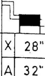 |  | 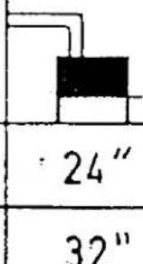 | 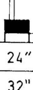 |
| FROM |  |  |  | 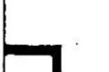 |  |
| TO | 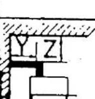 | 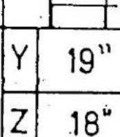 |  |  | 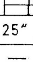 |
| SIZE OF HEARTH EXTENSION | |||||
| The hearth extension should be made of 3⁄4"asbestos millboard or equivalent | |||||
| L1 | 8" | 8" | 8" | 8" | |
| L2 | 8" | 8" | 8" | 8" | |
| L3 | 16" | 16" | 16" | 16" | |
| L4 | to wall | 2" | to wall | 8" | |
| Total width | 28" | 28" | 28" | 28" | |
| Total length | Min.63" | 46" | Min.63" | 43" | |
SIZE OF HEARTH EXTENSION
| The hearth extension should be made of 3/4"asbestos millboard or equivalent |  |  |  |  | |
| L_1 | 8" | 8" | 8" | 8" | |
| L_2 | 8" | 8" | 8" | 8" | |
| L_3 | 16" | 16" | 16" | 16" | |
| L_4 | to wall | 2" | to wall | 8" | |
| Total width | 28" | 28" | 28" | 28" | |
| Total length | Min.63" | 46" | Min.63" | 43" | |
Fig.1 Clearances and Hearth Extension Size
602
602


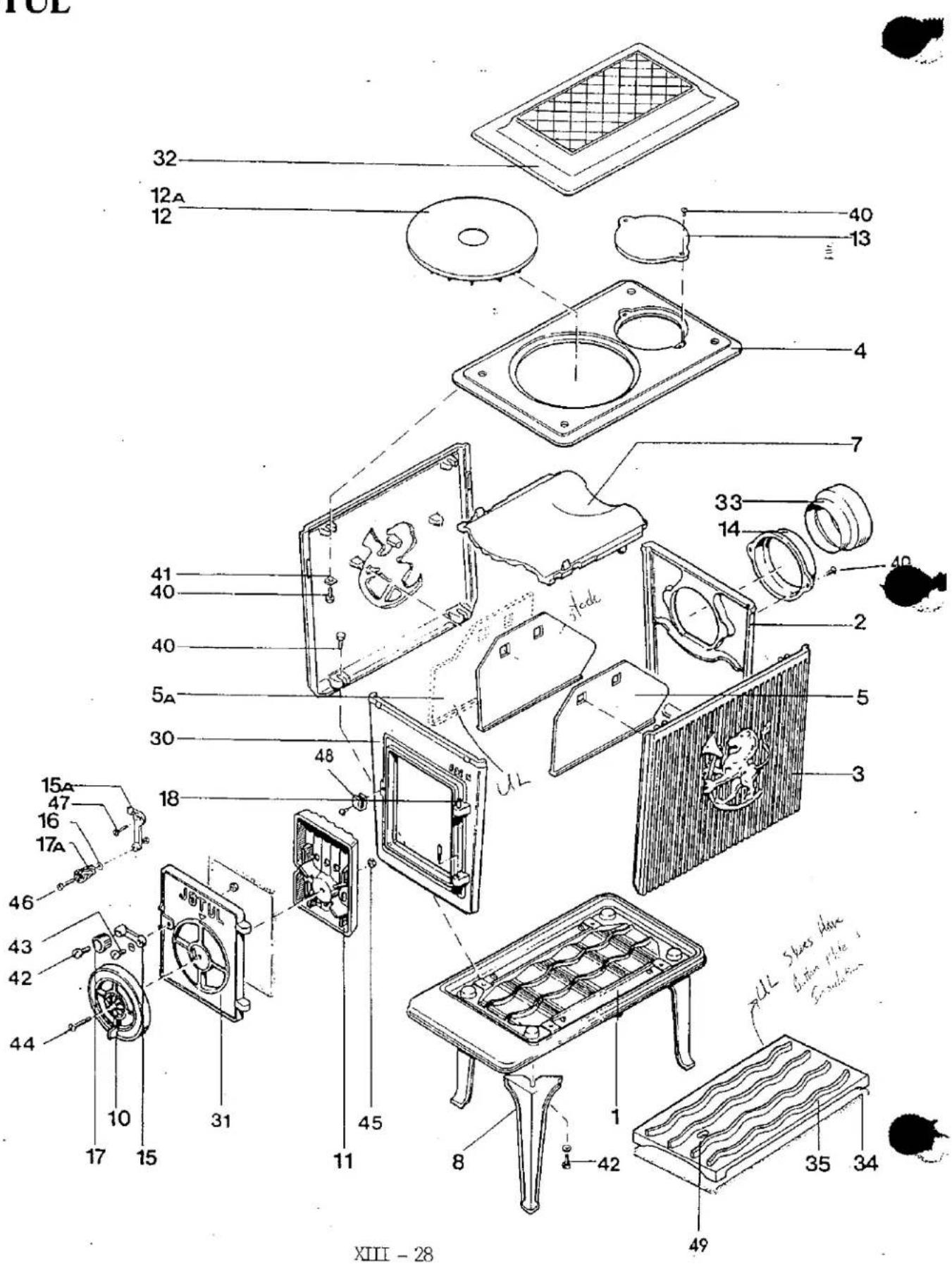
| SCH# DESCRIPTION | COLOR | UL | PART # | |
| 01 | Bottom plate | Blk | 101226 | |
| Blk-B | UL | 101547 | ||
| Blk-C | UL | 101686 | ||
| Grn | 100391 | |||
| Grn-B | UL | 101550 | ||
| Red-C | UL | 101732 | ||
| 02 | Back Plate | Blk | 101227 UCT H### | |
| Blk-C | UL | 101688 | ||
| Grn | 100392 U6 P## | |||
| Red-C | UL | 101733 | ||
| 03 | Side plate | Blk | 101228 NO | |
| Blk-C | UL | 101669 | ||
| Grn | 100393 | |||
| Red-C | UL | 101734 | ||
| 04 | Top plate | Blk | 101536 | |
| Blk-B | UL | 101539 | ||
| Blk-C | UL | 101690 | ||
| Grn | 101556 | |||
| Grn-B | UL | 101656 | ||
| Red-C | UL | 101735 | ||
| 05 | Side burn plate | 100330 10422012 | ||
| 05A | Side burn plate | UL | 101585 Not available | |
| 07 | Top baffle plate | 100396 10C39L | ||
| 08 | Leg | Blk B/C | 100817 | |
| Grn-B | 100382 | |||
| Red-C | UL | 101727 | ||
| 10 | Draft regulator | Blk B/C | 100608 | |
| Grn-B | 100387 | |||
| Red-C | UL | 101725 | ||
| 11 | Air flow plate | 100336 | ||
| 12 | Cookplate | 100898 | ||
| 12A | Cookplate | UL | 101557 | |
| 13 | Smoke hole cover | Blk | 100338 | |
| Blk-B | UL | 101540 | ||
| Blk-C | UL | 101700 | ||
| Grn | 100385 | |||
| Grn-B | UL | 101567 | ||
| Red-C | UL | 101730 | ||
Gram 320071 Matt 320073
| SCH# DESCRIPTION | COLOR | UL | PART # | |
| 14 - Smoke outlet | Blk | 100646 | ||
| Blk B/C | UL | 101559 | ||
| Gln | 100386 | |||
| Grn-B | UL | 101550 | ||
| Red-C | UL | 101729 | ||
| 15 | Cast iron door handle | 101085 | ||
| 15A | Cast iron door handle | UL | 101601 | |
| 16 | Insulated washer | UL | 124853 | |
| 17 | Bakelite knob | 120015 | ||
| 17A | Wooden knob | 124852 | ||
| 18 | Door pin | 120002 | ||
| 30 | Front complete w/ hook | Blk | 150806 | |
| Blk-B | 151185 | |||
| Blk-C | 151300 | |||
| Grn | 150393 | |||
| Grn-B | UL | 151186 | ||
| Red-C | UL | 151359 | ||
| 31 | Door | Blk | 101199 | |
| Grn | 100383 | |||
| Red | 101737 | |||
| 32 | Decorative top | Blk | 320009 | |
| Grn | 320006 | |||
| Red | 320042 | |||
| 33 | 125 mm to 6" adaptor | UL | 124817 | |
| 35 | Bottom burn plate | UL | 101519 | |
| 40 | M6 x 16 flat head screw | 9942 | ||
| 41 | M6 washer | 9975 | ||
| 42 | M6 x 25 cheese head screw | 9982 | ||
| 43 | M8 x 20 cheese head screw | 9989 | ||
| 44 | M8 x 25 flat head screw | 9948 | ||
| 45 | M8 hex nut | 9931 | ||
| 46 | M8 x 80 cheese head screw | 9996 | ||
| 47 | M8 x 25 cheese head screw | 9990 | ||
| 48 | Hook for handle | 120013 | ||
| 49 | M6 x 40 hex head screw | 9907 | ||

Brand : JOTUL
Model : 602 B-C
Category : Wood stove