Smith QuickSelect - Fitness Equipment INSPIRE - Free user manual and instructions
Find the device manual for free Smith QuickSelect INSPIRE in PDF.


| Product Type | Commercial Smith Machine |
| Brand | Inspire |
| Model | Smith QuickSelect |
| Total Weight Stack | 400 lbs (2 x 200 lbs) |
| Number of Weight Plates | 40 plates (10 lbs each) |
| Guide Rod Length | 2100 mm (approx 82.7 in) |
| Frame Dimensions (L x W x H) | Approx 86" x 30" x 84" |
| Minimum Floor Space Required | 20" clearance behind and sides |
| Assembly Required | Yes (2 people recommended) |
| Maintenance | Wipe with damp cloth and mild detergent; no solvents |
| Warranty | See inspirefitness.com/support |
| Safety | Consult physician before use; keep children away |
| Special Features | QuickSelect weight stack, counterbalanced bar, adjustable track bar |
| Parts List | Included in manual |
| Serial Number Location | Record on first page |
Frequently Asked Questions - Smith QuickSelect INSPIRE
User questions about Smith QuickSelect INSPIRE
0 question about this device. Answer the ones you know or ask your own.
Ask a new question about this device
Download the instructions for your Fitness Equipment in PDF format for free! Find your manual Smith QuickSelect - INSPIRE and take your electronic device back in hand. On this page are published all the documents necessary for the use of your device. Smith QuickSelect by INSPIRE.
USER MANUAL Smith QuickSelect INSPIRE
natural_image
Technical line drawing of two industrial lifting cabinets (no text or symbols visible)Record Serial Number Here
Centr LLC
80009-V2024-04-17
CONGRATULATIONS
Welcome to the Inspire Fitness Family. You've just taken the first step to a healthier and stronger body. This CSM, Commercial Smith Machine by Inspire Fitness offers the key to unlocking your body's potential. Regular weight training has been shown to deliver a host of benefits including: increased muscle tone, decreased body fat, improved energy levels, and a reduction in stress. Congratulations, you are on your way to improving your self image, overall health, and quality of life.
BEFORE ASSEMBLING YOUR CSM
IMPORTANT: Read this entire manual before attempting to build or use this machine. This manual contains step by step instructions for proper assembly.
Use the parts list included in this manual to verify that all parts are accounted for before assembly. If any parts are missing, contact Inspire Fitness Support for replacement parts through email, by phone or through chat.
This Inspire Fitness Smith Machine is intended for Commercial use. Rust can form on certain parts in a humid environment, resulting in impaired function.
CONTACT US FOR HELP
Service of your Commercail Smith Machine should only be performed by an Inspire Fitness Authorized Servicer. Service performed by anyone else can result in loss of warranty. If you need help finding an Inspire Fitness Authorized Servicer, please contact us directly:

Hello@centr.com

Phone
+1 877-738-1729 (US Only)
+1 714-738-1729 (Global)
Mon-Fri 8am-5pm PT - UTC-7h/8h
*Support is provided in English and Spanish*
TABLE OF CONTENTS
IMPORTANT SAFETY NOTICE....6
IMPORTANT SAFETY INSTRUCTIONS....7
GROUND ANCHORING....7
WARNING AND SERIAL NUMBER LABELS......8
ASSEMBLY HARDWARE KIT....9
ASSEMBLY INSTRUCTIONS....12
EXPLODED VIEW....23
PARTS LIST....24
PRODUCT WARRANTY....25
IMPORTANT SAFETY NOTICE
PRECAUTIONS
This exercise machine is built for optimum safety. However, certain precautions apply whenever you operate a piece of exercise equipment. Be sure to read the entire manual before you assemble or operate your machine. Please note the following safety precautions:
- Consult your physician before beginning any exercise program
- Always keep children and pets away from the machine. DO NOT leave children unattended in the same room with the machine. The linkages on this machine can cause serious injury or death if used improperly.
- Never place your hands or feet in the path of the linkages because injury may occur to you or damage may occur to the equipment. Never allow children to come near or approach the moving linkages while in use.
- If the user experiences dizziness, nausea, chest pain, or any other abnormal symptoms, STOP the workout at once. CONSULT A PHYSICIAN IMMEDIATELY.
- Position the machine on an open and level surface.
- DO NOT use the machine outdoors or near water.
- Keep hands away from all moving parts.
- Always wear appropriate workout clothing when exercising. DO NOT wear robes or other clothing that could become caught in the machine. Running or training shoes are also required when using the machine.
- Use the machine only for its intended use as described in this manual. DO NOT use attachments not recommended by the manufacturer.
- DO NOT place any sharp objects around the machine.
- Disabled persons should not use the machine without a qualified person or physician in attendance.
- Before using the machine to exercise, perform stretching exercises to properly warm up.
Care and Maintenance
- Keep moving parts clean.
- DO NOT use or store equipment outdoors
- Inspect and tighten all parts before using the machine.
- The frame can be cleaned using a damp cloth and mild non abrasive detergent. DO NOT use solvents.
WARNING: BEFORE BEGINNING ANY EXERCISE PROGRAM, CONSULT YOUR PHYSICIAN. THIS IS ESPECIALLY IMPORTANT FOR INDIVIDUALS OVER THE AGE OF 35 OR PERSONS WITH PRE-EXISTING HEALTH PROBLEMS. READ ALL INSTRUCTIONS BEFORE USING ANY FITNESS EQUIPMENT. Health In Motion, LLC. DOES NOT ASSUME ANY RESPONSIBILITY FOR PERSONAL INJURY OR PROPERTY DAMAGE SUSTAINED BY OR THROUGH THE USE OF THIS PRODUCT.
IMPORTANT SAFETY INSTRUCTIONS
WARNING: BEFORE BEGINNING ANY EXERCISE PROGRAM, CONSULT YOUR PHYSICIAN. THIS IS ESPECIALLY IMPORTANT FOR INDIVIDUALS OVER THE AGE OF 35 OR PERSONS WITH PRE-EXISTING HEALTH PROBLEMS. READ ALL INSTRUCTIONS BEFORE USING ANY FITNESS EQUIPMENT. Centr LLC. DOES NOT ASSUME ANY RESPONSIBILITY FOR PERSONAL INJURY OR PROPERTY DAMAGE SUSTAINED BY OR THROUGH THE USE OF THIS PRODUCT. THIS MACHINE REQUIRES 2 PEOPLE FOR ASSEMBLY.
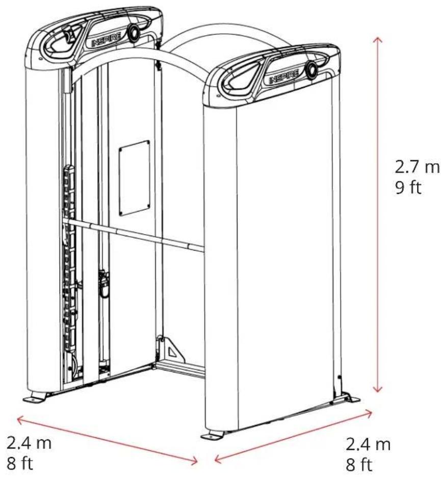
SPACE REQUIREMENTS
This Commercial Smith Machine requires a minimum amount of floor space and ceiling height to safely operate. Keep a minimum open area of 20" (0.5m) behind, and 20" (0.5m) on both sides.
GROUND ANCHORING
This Commercial Smith Machine SHOULD be bolted to the ground to avoid moving or creeping of the machine while in use with a heavy load.
LIVE AREA
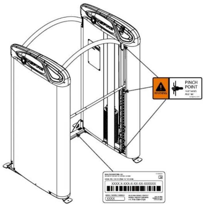
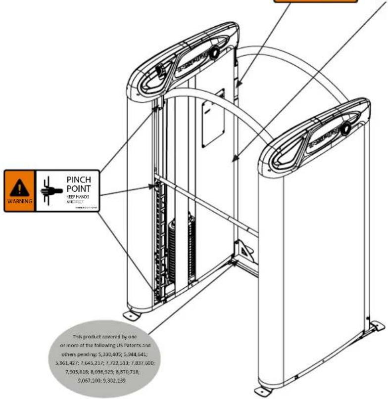
WARNING AND SERIAL NUMBER LABELS
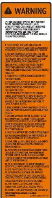
| NOTICE | ||||
| CONSUMMER MOUNTIDANCE | IN US$ | VEGET | EXPANSO | S&P 500 |
| Import: Global Public Health, National Health, and Family | × | |||
| Home Technology | × | |||
| Import: Japan and Other Holdings | × | |||
| Import: Technology & Services | × | |||
| Import: Anniversary and Benefits | × | |||
| Import: All Goods | × | |||
| Import: Oil and Gas, Transportation, Retail, and Insurance | × | |||
| Import: Oil and Gas, Water | × | |||
| Commercial Goods, Apparel, and Home Goods, and Food | × | |||
| Laboratory Care, General, and Medical Services | × | |||
| Consumer Goods, Office, and Media | × | |||
| Retail, 2-3 Stores, Home, and Commercial, etc. | × | |||
ASSEMBLY HARDWARE KIT
CSM-2 103444
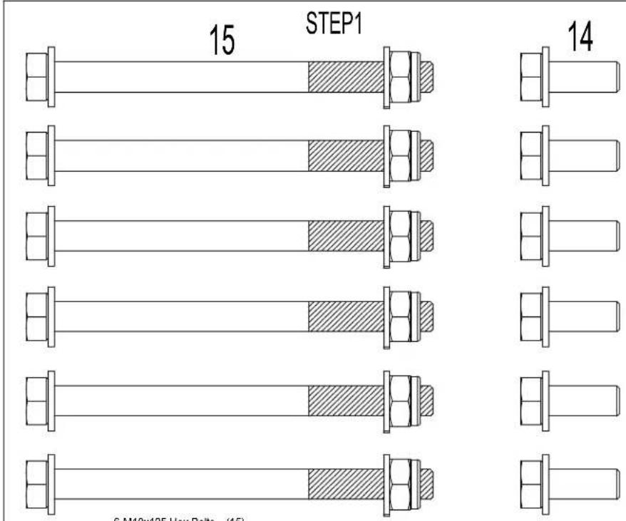
6-M10x125 Hex Bolts - (15)
8-M10x25 Hex Bolts - (14)
20-M10 Flat Washers - (12)
6-M10 Locknuts - (13)
STEP2
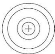
4- Countersunk Flat Cushion -(16)
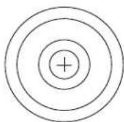
4-M8x20 Flat Head Screws - (17)
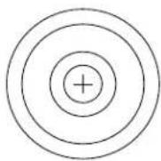
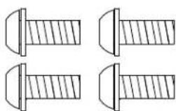
4 - M8 x 20 Button Head Bolts -(52)
4 - M8 Flat Washers -(31)
16
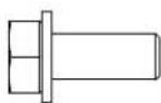
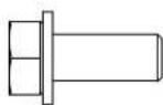
17
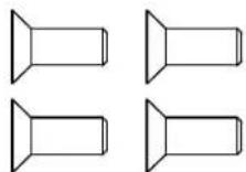
52
natural_image
Four technical line drawings of screw fasteners with no text or symbolsHARDWARE PACK (NOT TO SCALE)
ASSEMBLY HARDWARE KIT
CSM-2 103445
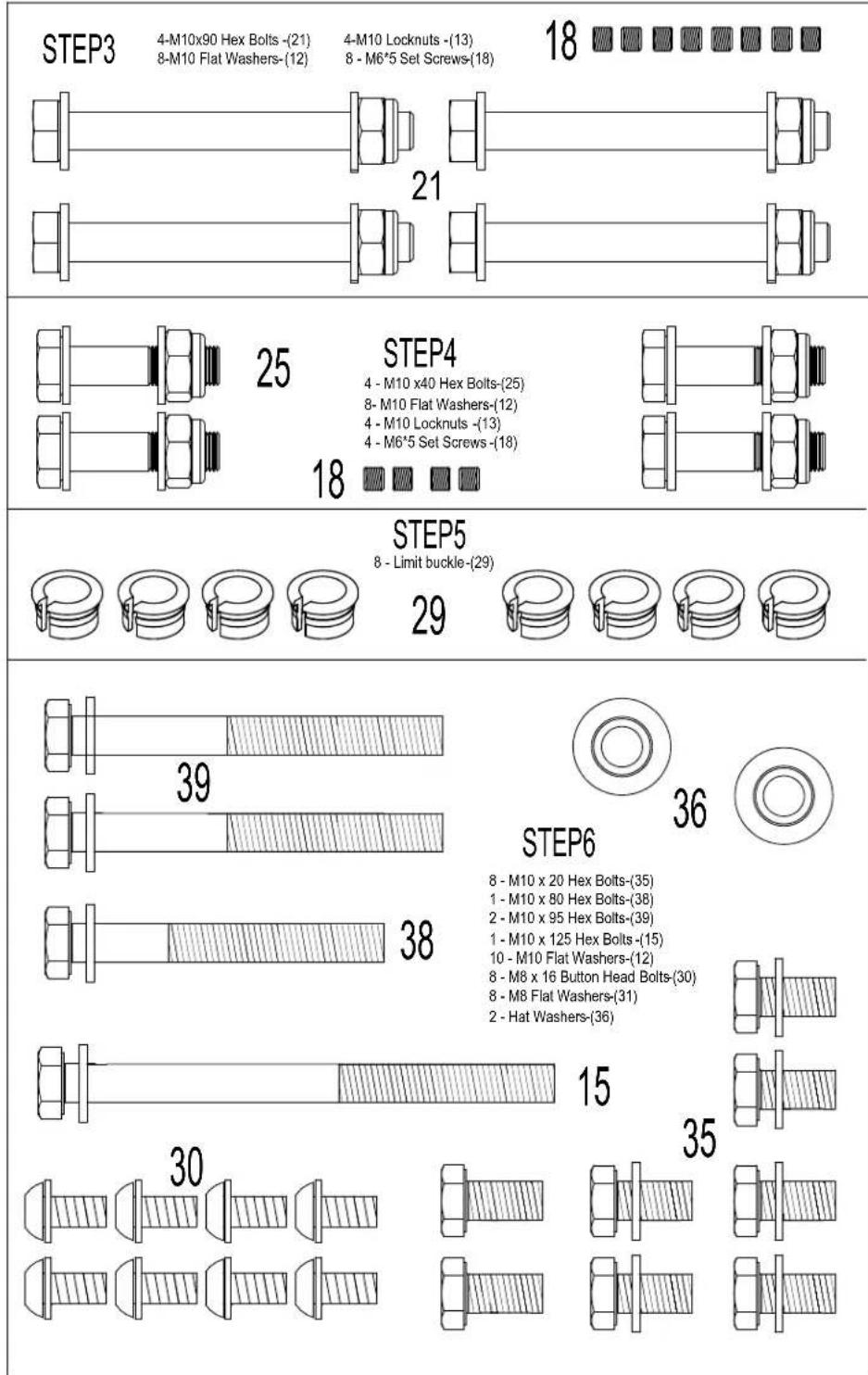
HARDWARE PACK CONTINUED (NOT TO SCALE SCALE)
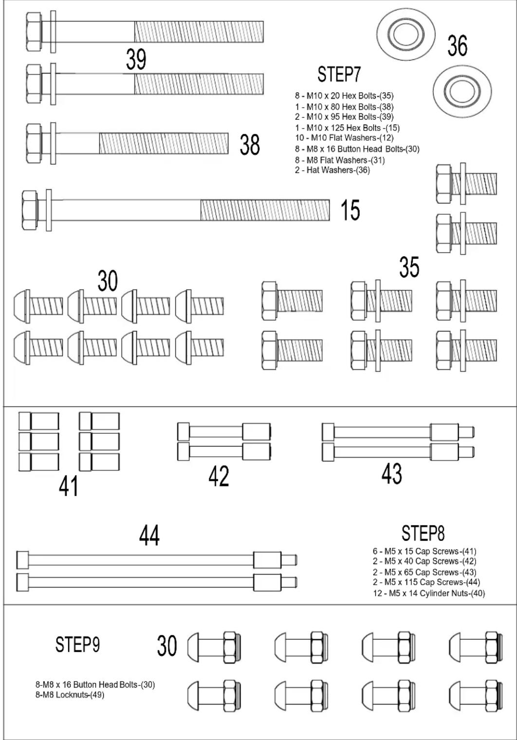
ASSEMBLY HARDWARE KIT
CSM-2 103446
other
| Step | Number of Bolts | Washers | |------|-----------------|---------| | 1 | 39 | | | 2 | 38 | | | 3 | 15 | | | 4 | 30 | | | 5 | 35 | | | 6 | 41 | | | 7 | 42 | | | 8 | 43 | | | 9 | 44 | | | 10 | | | | 11 | | | | 12 | | | | 13 | | | | 14 | | | | 15 | | | | 16 | | | | 17 | | | | 18 | | | | 19 | | | | 20 | | | | 21 | | | | 22 | | | | 23 | | | | 24 | | | | 25 | | | | 26 | | | | 27 | | | | 28 | | | | 29 | | | | 30 | | | | 31 | | | | 32 | | | | 33 | | | | 34 | | | | 35 | | | | 36 | | | Step7: M10 x 20 Hex Bolts-(35) M10 x 80 Hex Bolts-(38) M10 x 95 Hex Bolts-(39) M10 x 125 Hex Bolts-(15) M10 Flat Washers-(12) M8 x 16 Button Head Bolts-(30) M8 Flat Washers-(31) Hat Washers-(36) STEP8: M5 x 15 Cap Screws-(41) M5 x 40 Cap Screws-(42) M5 x 65 Cap Screws-(43) M5 x 115 Cap Screws-(44) M5 x 14 Cylinder Nuts-(40)HARDWARE PACK CONTINUED (NOT TO SCALE)
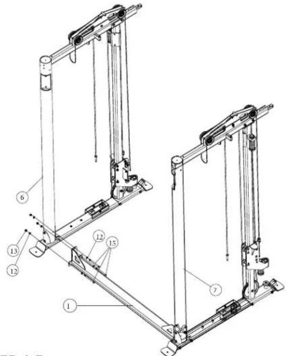
FRAME ASSEMBLY
STEP 1-A Assemble Lower Cross Brace (1) to Main Frame Left (7), secure with Bolt (15), Washer (12) and Nut (13). DO NOT FULLY TIGHTEN YET.
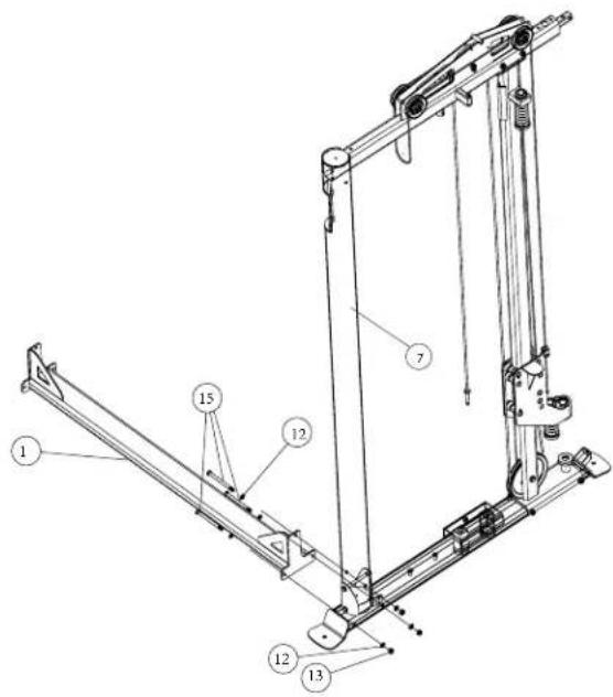
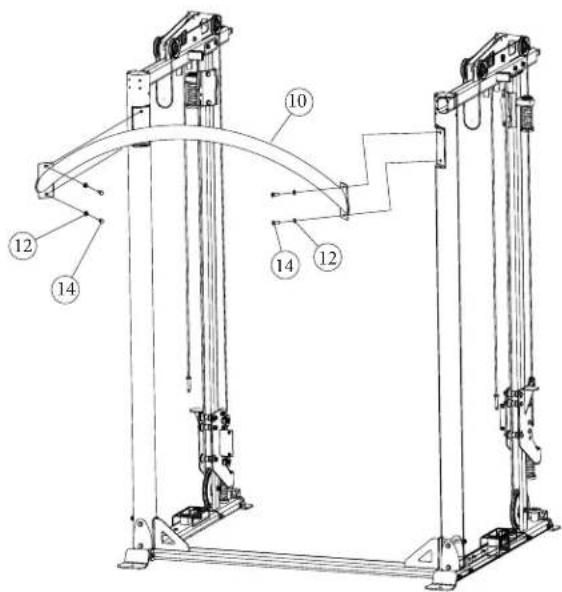
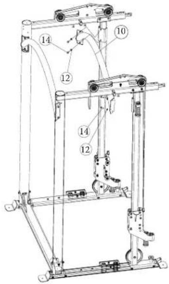
STEP 1-C. Install Upper CrossBar (10) to the Upright frame on Rear side, Secure with Bolt (14), Washer (12). DO NOT FULLY TIGHTEN YET.
STEP 1-B Assemble Lower Cross Brace (1) to Main Frame Right (6), secure with Bolt (15), Washer (12) and Nut (13). DO NOT FULLY TIGHTEN YET.
STEP 1-D Install Upper CrossBar (10) to the Upright frame on Front side, Secure with Bolt (14), Washer (12). FULLY TIGHTEN all hardware at this point.
TRACK BAR INSTALLATION
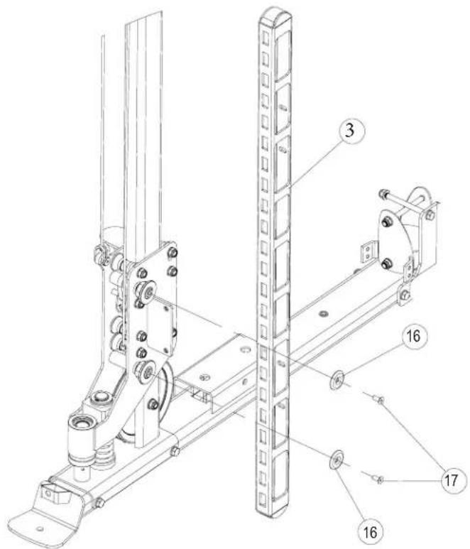
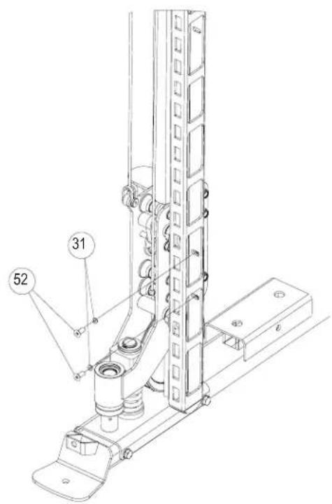
STEP 2-A Install TUBULAR Rack (3) to Sliders Left and right side, secure with Bolt (17), Washer (16). Secure in place.
STEP 2-B Install Bolt (52), Washer (31) To Secure in place.
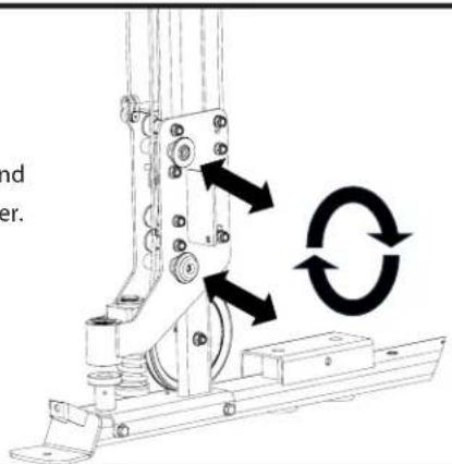
If needed.
The trackbar can be adjusted in and out by turning the threaded spacer.
GUIDE ROD AND SMITH BAR INSTALLATION
INSTALL SET SCREWS TOP
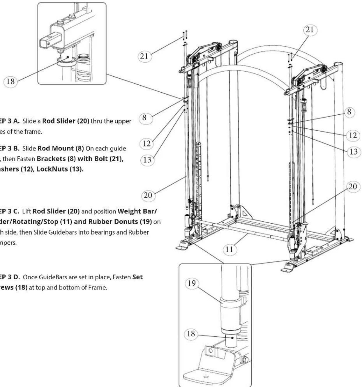
INSTALL SET SCREWS BOTTOM
INSTALL WEIGHT PLATES
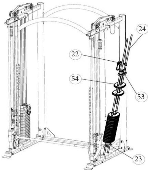
STEP 4 A. Insert the Guide Rods (24) through the holes in the bottom of the frame. Be sure the ends of the rods with the holes are facing Up.
STEP 4 B. Slide a Rubber Bumper (23) on each of the Guide Rods (24). let them rest at bottom of Guide Rod.
STEP 4 C. Let the Guide Rods (24) rest at an angle in the frame. Using the provided lubricant, spread the liquid up and down the guide rods. Then slide on 20 Weight Plates (54) with the sticker cut out facing towards the inside of the machine and the protruding pads on the weights facing downward.
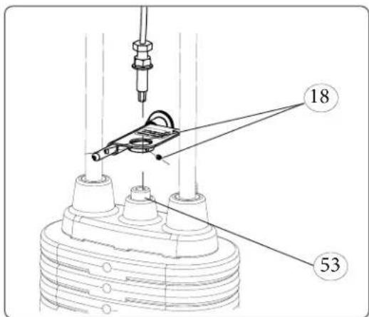
STEP 4 D Next slide on the Top Weight/Selector Stem (53). then place Weight Stack Pin (22) on top
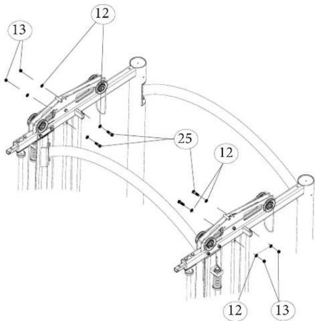
STEP 4 E. Align GuideRods with top holes on the frame, and secure in place with Bolt (25) Washer(12, Nut (13))
STEP 4 F. Secure Weight Stack Pin (22) to Top Weight/Selector Stem (53) by threading in the cable end in place. Fasten Screws (18) to Weight Stack Pin (22) and Top Weight/Selector Stem (53)
REPEAT FOR OPPOSITE SIDE.
COUNTER WEIGHTS INSTALLATION
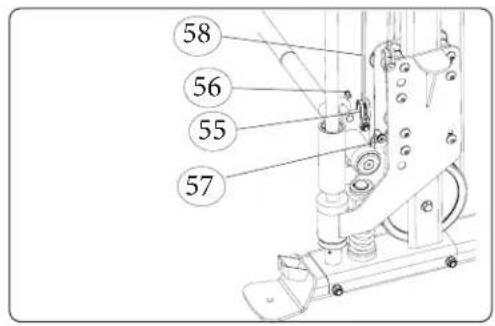
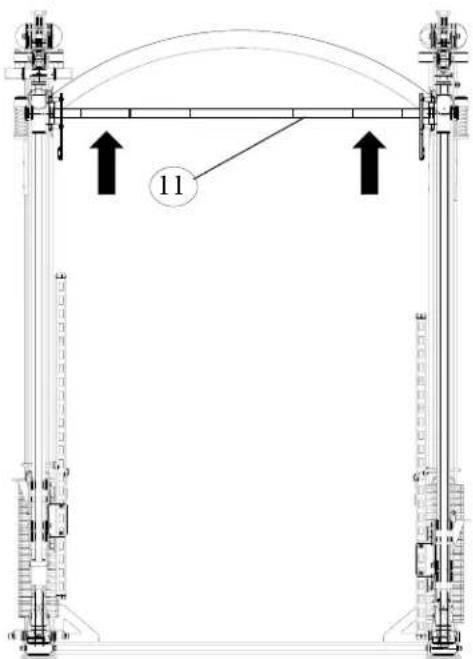
STEP 5 A. Install Counterweight cable (58) to Weight bar (11) with U Braclet(55), Bolt (56) and Bolt (57). Then move Weight Bar (11) to its highest position.
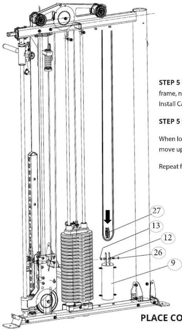
STEP 5 B. Set Counter Balance Weight (9) At bottom of the frame, next to the weightstack. Pull cable to its lowest position, then Install Cable and pulley to counter weight.
STEP 5 C. Fasten with Bolt (26), Washer (12), and Nut (13).
When lowering the Weight bar, the counter balance weight should move up.
Repeat for opposite side.
PLACE COUNTER WEIGHT AT BOTTOM OF FRAME
REPEAT FOR OPPOSITE SIDE.
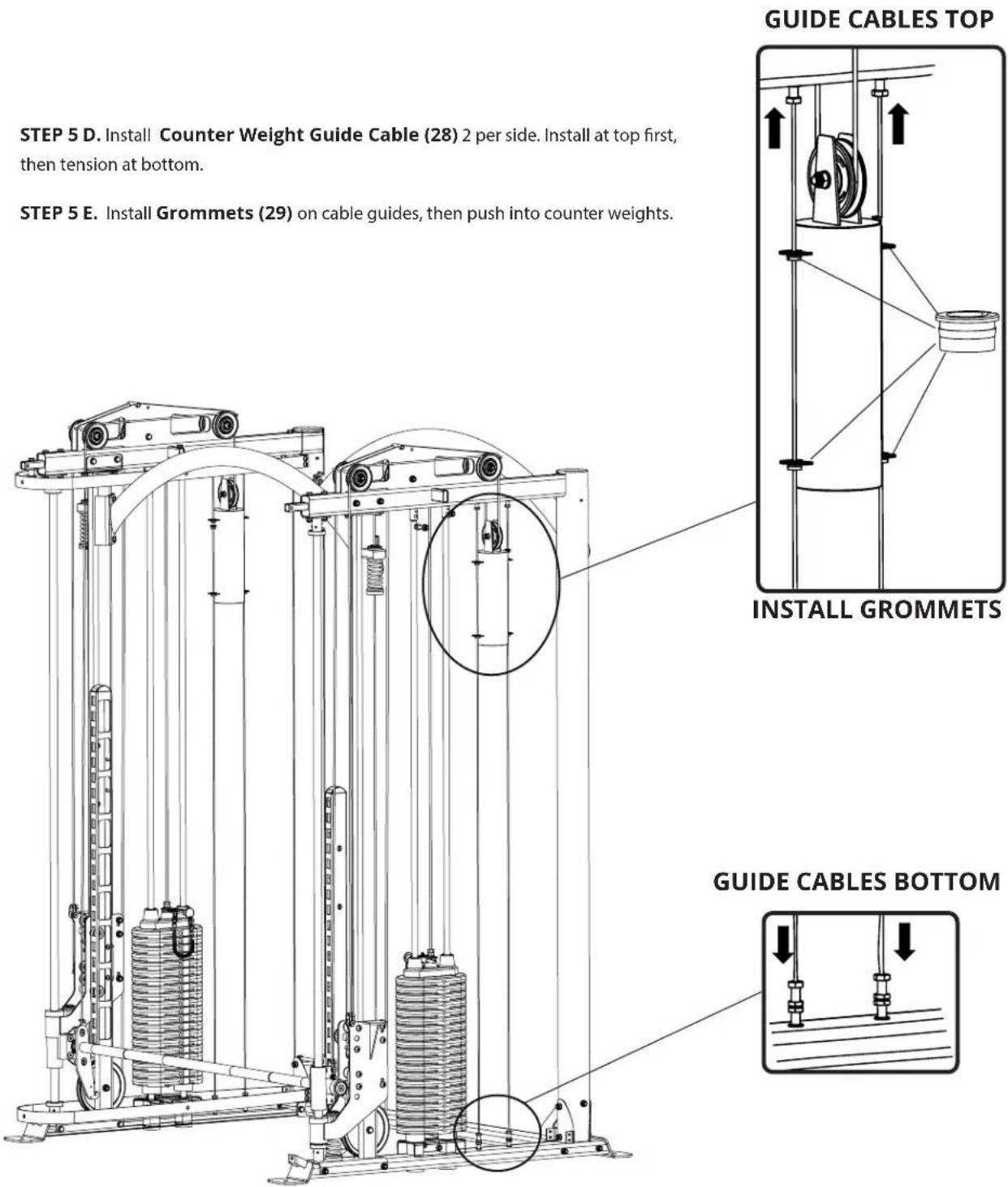
STEP 5 D. Install Counter Weight Guide Cable (28) 2 per side. Install at top first, then tension at bottom.
STEP 5 E. Install Grommets (29) on cable guides, then push into counter weights.
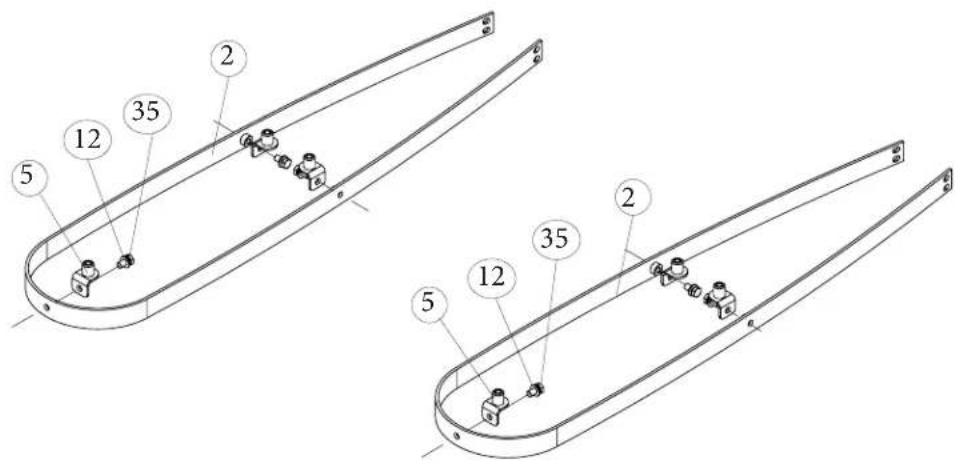
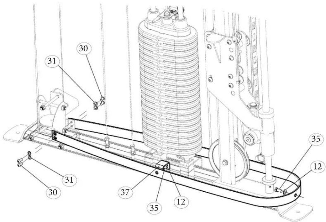
STEP 6-A Install 3 Upper Leveling Brackets (5) Bolts (35) Washer (12) to build Shroud Mount Loop (2) for top. 1 for left side, 1 for right side. Hand tighten bolts.
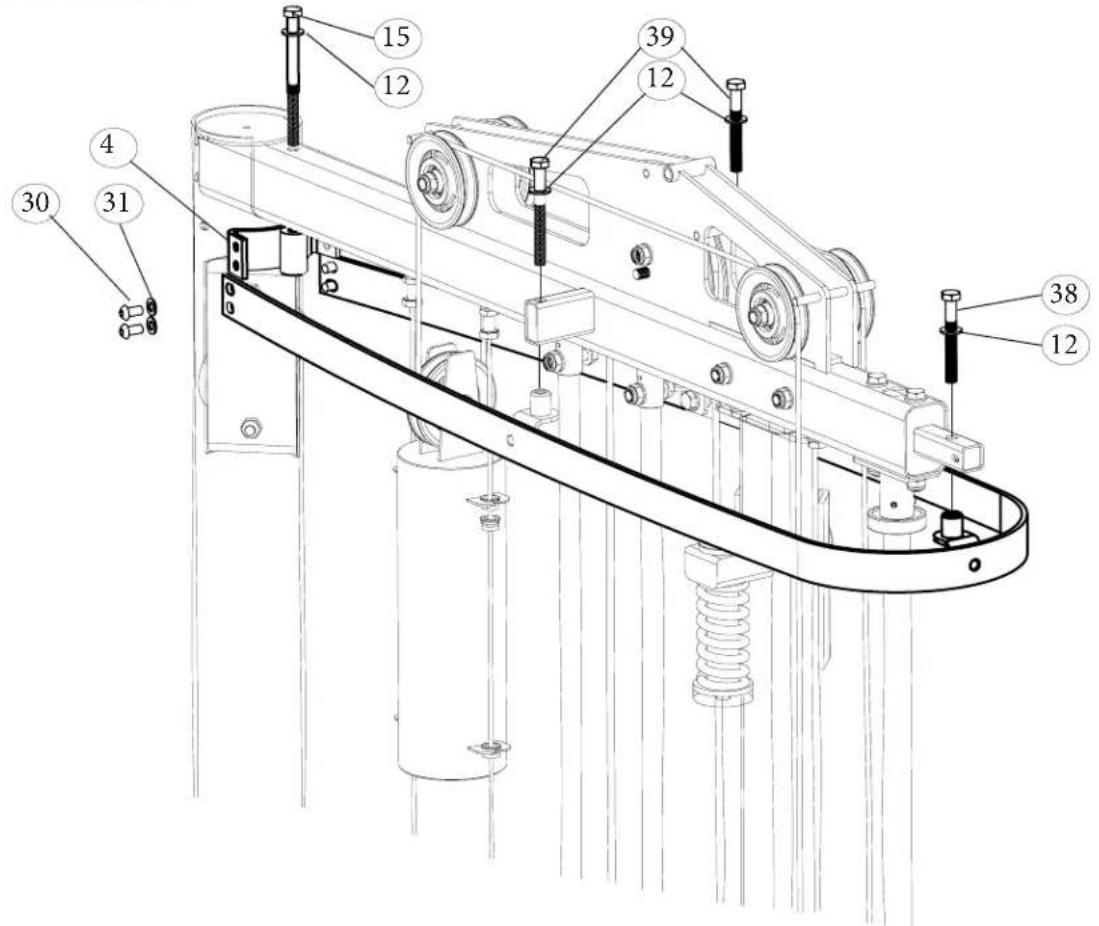
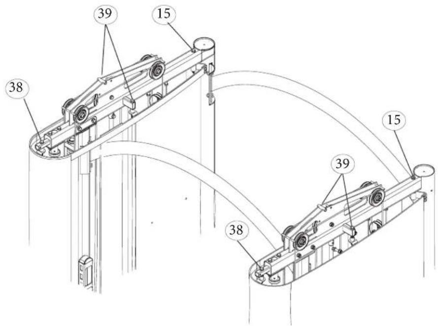
STEP 6-B Install Rear Upper Shroud Mount brackets (4) (LEFT AND RIGHT SIDE) to the Upright Frames with Bolt (15), Screw the Upper Leveling Brackets with the Bolts (30) and the Washers (31). Install 2 Bolts (39), 1 Bolt (38) with the Washers (12) to the frame and the brackets. Leave the Bolts (15)(38)(39) loose, they will be tensioned after shroud installation.
STEP 6-C Install 2 Bolts (35) with Spacers (36) to build Shroud Loop (2) for Lower frame. 1 for left side, 1 for right side. Hand tighten bolts.
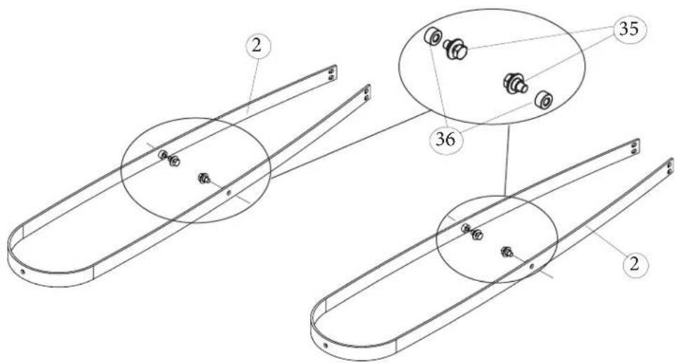
STEP 6-D Install Lower Shroud Mount brackets (37) to the Upright Frames with Bolts (35) and Washers (12) on two sides. Make sure side Bolts (35) and Spacers (36) are located correctly on the Bracket. Fasten Bolts (35) Washer (12), Side Bolts (30) Washer (31) to the Main Frame. 1 for left side, 1 for right side. Hand tighten bolts.
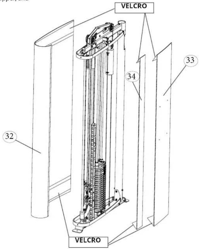
STEP 7 A Install Main Shroud(32) Wraps on the OUTSIDE
of the frame. Open the velcro and wrap around upper, and then Lower Bracket.
STEP 7 B Install Rear Shroud(33)
Wraps on the INSIDE of the frame. From the Right of the weightstack to the back
STEP 7 C Install Middle Shroud(34) This is the shortest piece. Wraps on the inside from the left of the weightstack towards the front of the frame.
STEP 7 D With all Shrouds in place, tension covers by turning bolts (15)(38)(39) at top of the frame.
TOP COVER INSTALLATION
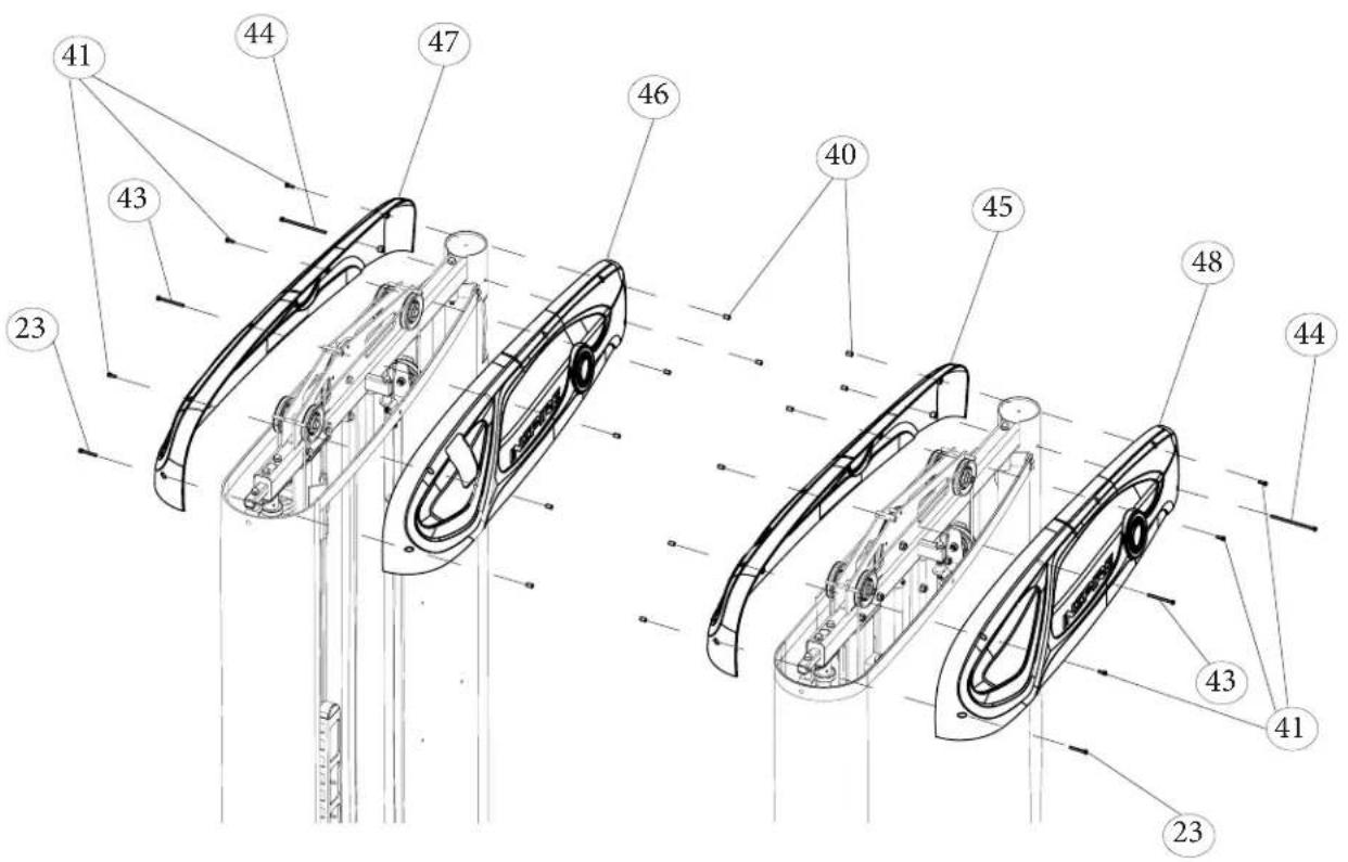
STEP 8 A Install Inner Right Top Cover (46) and Outer RightTop Cover(47). Locate where the 2 pieces will go, secure using Bolts (41)(43)(44)(47)(23), and Threaded Cylinders (40) on opposite side, as illustrated below.
STEP 8 B Repeat installation process for opposite side for Inner Left Top Covers (45) and Outer Left Top Cover (48).
PLACARDS INSTALLATION
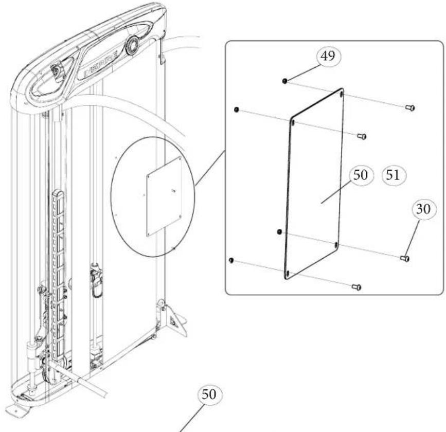
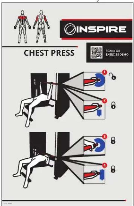
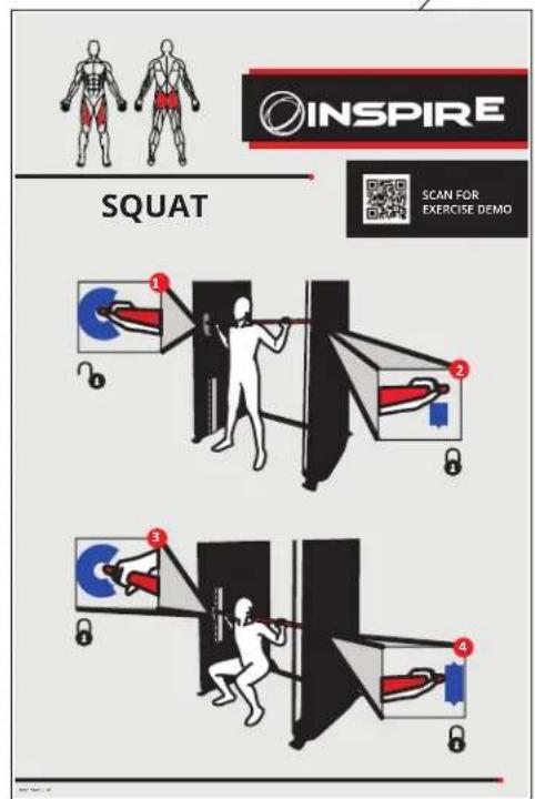
STEP 9 Install Placards (50) and (51) to right and left inner part of shroud. Use Bolt 30, LockNut (49) to secure in place. There are 2 different placards, one for Left side, one for Right side.
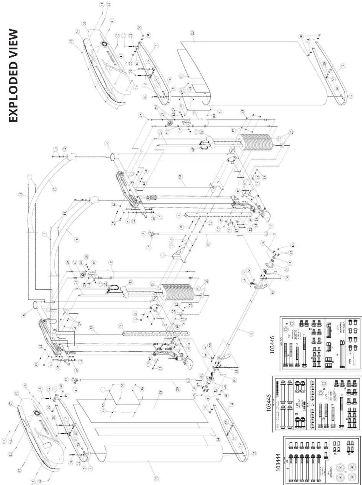
| No. | Description Part Number Qty | ||
| 1 | WLDMT, LOWER CROSS BRACE 102451 1 | ||
| 2 | WLDMT, SHROUD LOOP, CSM2 102593 4 | ||
| 3 | TUBE, TUBULAR RACK 102550 2 | ||
| 4 | WLDMT, REAR UPPER SHROUD BRACKET, CSM2 102598 2 | ||
| 5 | UPPER LEVELING BRACKET, CSM2 102601 6 | ||
| 6 | ASSY, MAIN FRAME, RH 102455 1 | ||
| 7 | ASSY, MAIN FRAME, LH | 102538 1 | |
| 8 | ASSY, SLIDE ROD MOUNT, CSM2 | 102576 2 | |
| 9 | WLDMT, COUNTER BALANCE WEIGHT, CSM2 | 102584 2 | |
| 10 | WLDMT, UPPER CROSSBAR | 102547 2 | |
| 11 | ASSY, SMITH WEIGHT BAR | 102554 1 | |
| 12 | WASHER, FLAT, 10.5 X 20 X 2, BZ | 102390 | 62 |
| 13 | NUT, M10 X 1.5 X 10, LOCK, CL8, BZ 102391 | 14 | |
| 14 | BOLT, M10 X 1.5 X 25, HH, CL 8.8, BZ | 102660 8 | |
| 15 | BOLT, M10 X 1.5 X125, HH, CL 8.8, BZ 102650 8 | ||
| 16 | WASHER, TUBULAR RACK | 102551 4 | |
| 17 | BOLT, M8 X 1.25 X 20, FH, CL 10.9, BZ | 102552 4 | |
| 18 | SCREW, M6 X 1.0 X 5, SET, CUP, BZ | 102520 4 | |
| 19 | RUBBER DONUT, 25 ID | 102580 2 | |
| 20 | ROD, SLIDER, 25 OD X 2080L | 102575 2 | |
| 21 | BOLT, M10 X 1.5 X 90, HH, CL 8.8, BZ | 102651 | 4 |
| 22 | ASSY, WEIGHT STACK PIN-LANYARD 102620 2 | ||
| 23 | RUBBER DONUT, 60 X 20 X 28 | 102582 4 | |
| 24 | GUIDE ROD, 2100MM, CSM2 | 102581 4 | |
| 25 | BOLT, M10 X 1.5 X 40, HH, CL 8.8, BZ | 102661 4 | |
| 26 | BOLT, M10 X 1.5 X 50, HH, CL 8.8, BZ | 102652 2 | |
| 27 | ASSY, 3" CABLE PULLEY | 102535 6 | |
| 28 | ASSY, GUIDE CABLE, 2156, CSM2 | 102589 4 | |
| 29 | GROMMET, 16 OD | 102588 8 | |
| 30 | BOLT, M8 X 1.25 X 16, BH, CL 10.9, BZ | 102665 | 24 |
| 31 | WASHER, FLAT, 8.5 X 16 X 1.6, BZ 102593 | 20 | |
| 32 | SHROUD, MAIN, CSM2 | 102604 2 | |
| 33 | SHROUD, REAR, CSM2 102606 2 | ||
| 34 | SHROUD, MIDDLE, CSM2 | 102605 2 | |
| 35 | BOLT, M10 X 1.5 X 20, HH, CL 8.8, BZ | 102666 | 16 |
| 36 | SPACER, STEP, SHROUD, CSM2 | 102597 4 | |
| 37 | BRACKET, LOWER SHROUD MOUNTING, CSM2 | 102596 4 | |
| 38 | BOLT, M10 X 1.25 X 80, HH, CL 8.8, BZ | 103368 2 | |
| 39 | BOLT, M10 X 1.5 X 95, HH, CL 8.8, BZ | 103369 4 | |
| 40 | NUT, SOCKET, M5 X 0.8 X 11, BZ | 102670 | 12 |
| 41 | BOLT, M5 X 0.8 X 15, SH, CL 12.9, BZ | 102671 | 6 |
| 42 | BOLT, M5 X 0.8 X 40, SH, CL 12.9, BZ | 102672 | 2 |
| 43 | BOLT, M5 X 0.8 X 65, SH, CL 12.9, BZ | 102673 | 2 |
| 44 | BOLT, M5 X 0.8 X 115, SH, CL 12.9, BZ | 103374 | 2 |
| 45 | ASSY, INNER TOP COVER, LH, CSM2 | 102615 | 1 |
| 46 | ASSY, INNER TOP COVER (W/CUTOUT), RH, CSM2 | 102611 | 1 |
| 47 | ASSY, OUTER TOP COVER, RH, CSM2 | 102607 | 1 |
| 48 | ASSY, OUTER TOP COVER, LH, CSM2 | 102613 | 1 |
| 49 | NUT, M8 X 12.5 X 8, LOCK, CL 8, BZ | 103128 | 8 |
| 50 | PLACARD, SQUAT, INSPIRE, CSM2 | 80024 | 1 |
| 51 | PLACARD, CHEST PRESS, INSPIRE, CSM2 | 80025 | 1 |
| 52 | BOLT, M8 X 1.25 X 20, BH, CL 10.9, BZ | 102392 | 4 |
| 53 | ASSY, TOP WEIGHT/SELECTOR STEM | 102621 | 2 |
| 54 | WEIGHT, PLATE, 10LBS | 102626 | 40 |
| 55 | BRACKET, U, CABLE END | 102656 2 | |
| 56 | BOLT, M6 X 1.0 X 12, BH, CL 10.9 | 102659 2 | |
| 57 | BOLT, INTERNAL THREAD, M10 X 22 | 102657 2 | |
| 58 | CABLE, COUNTER BALANCE, 5560 102537 2 | ||
| 59 | ASSY, SMITH LINEAR BEARING | 102558 2 | |
| 60 | ASSY, ROTATING/STOP PIN | 102564 2 | |
| 61 | HARDWARE CARD 1, CSM2 | 103444 1 | |
| 62 | HARDWARE CARD 2, CSM2 | 103445 1 | |
| 63 | HARDWARE CARD 3, CSM2 | 103446 1 | |
| 64 | WEIGHT BAR END CAP | 102571 2 | |
| 65 | BOLT, M10 X 1.5 X 20, FH, CL 10.9, BZ | 102572 4 | |
| 66 | BOLT, M10 X 1.5 X 30, FH, CL 10.9, BZ | 102573 6 | |
| 67 | NUT, M10 X 1.5 X 10, LOCK, CL 8, BZ | 102391 6 |
PRODUCT WARRANTY
To view full warranty details, or to register your product for warranty, visit inspirefitness.com/support
AUSTRALIA
Our goods come with guarantees that cannot be excluded under the Australian Consumer. You are entitled to a replacement or refund for a major failure and for compensation for any other reasonably foreseeable loss or damage. You are also entitled to have the goods repaired or replaced if the goods fail to be of acceptable quality and the failure does not amount to a major failure.
Our goods and services come with guarantees that cannot be excluded under the Australian Consumer Law. For major failures with the service, you are entitled:
• to cancel your service contract with us; and
- to a refund for the unused portion, or to compensation for its reduced value.
You are also entitled to choose a refund or replacement for major failures with goods. If a failure with the goods or a service does not amount to a major failure, you are entitled to have the failure rectified in a reasonable time. If this is not done you are entitled to a refund for the goods and to cancel the contract for the service and obtain a refund of any unused portion. You are also entitled to be compensated for any other reasonably foreseeable loss or damage from a failure in the goods or service.

INSPIRE BY CENTR
www.inspirefitness.com
- CONGRATULATIONS
- BEFORE ASSEMBLING YOUR CSM
- CONTACT US FOR HELP
- Phone
- TABLE OF CONTENTS
- IMPORTANT SAFETY NOTICE
- PRECAUTIONS
- Care and Maintenance
- IMPORTANT SAFETY INSTRUCTIONS
- SPACE REQUIREMENTS
- GROUND ANCHORING
- LIVE AREA
- WARNING AND SERIAL NUMBER LABELS
- ASSEMBLY HARDWARE KIT
- STEP2
- FRAME ASSEMBLY
- TRACK BAR INSTALLATION
- If needed.
- GUIDE ROD AND SMITH BAR INSTALLATION
- INSTALL WEIGHT PLATES
- REPEAT FOR OPPOSITE SIDE.
- COUNTER WEIGHTS INSTALLATION
- STEP 7 A Install Main Shroud(32) Wraps on the OUTSIDE
- STEP 7 B Install Rear Shroud(33)
- TOP COVER INSTALLATION
- PLACARDS INSTALLATION
- PRODUCT WARRANTY
- AUSTRALIA
- INSPIRE BY CENTR
Brand : INSPIRE
Model : Smith QuickSelect
Category : Fitness Equipment