
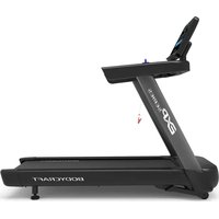
T800 - Treadmills BodyCraft - Free user manual and instructions
Find the device manual for free T800 BodyCraft in PDF.


| Product Type | Treadmill |
| Brand | BodyCraft |
| Model | T800 |
| Motor Power | 3.0 CHP, quiet drive system |
| Speed Range | 0.5 - 12 mph (0.8 - 19.3 km/h) |
| Incline Range | 0% - 15% powered incline |
| Running Surface | 22" x 60" (56 x 152 cm) |
| Display | 7.5" blue backlit LCD with feedback: time, distance, speed, incline, heart rate, calories, pulse |
| Heart Rate Monitoring | Wireless chest strap compatible (Polar) + hand pulse sensors |
| Programs | 21 pre-set programs, 3 user-custom, 2 heart rate control |
| Folding Design | Yes, with Easy Assist folding system |
| Dimensions (Assembled) | 79" L x 36" W x 57" H (201 x 91 x 145 cm) |
| Weight | 319 lbs (145 kg) |
| User Weight Capacity | 400 lbs (181 kg) |
| Power Requirements | 120V, 15A, dedicated circuit |
| Warranty | Frame: lifetime, motor: 5 years, electronics: 2 years, labor: 1 year |
| Roller Diameter | 2.5" precision machined crown rollers |
| Deck Type | Premium orthopedic, 4-layer reversible |
| Cushioning | Advanced cushioning system with impact zones |
| Safety Features | Safety key tether, emergency stop, child lock |
Frequently Asked Questions - T800 BodyCraft
User questions about T800 BodyCraft
0 question about this device. Answer the ones you know or ask your own.
Ask a new question about this device
Download the instructions for your Treadmills in PDF format for free! Find your manual T800 - BodyCraft and take your electronic device back in hand. On this page are published all the documents necessary for the use of your device. T800 by BodyCraft.
USER MANUAL T800 BodyCraft

To see in FULL COLOR & additional information, scan this QR code.

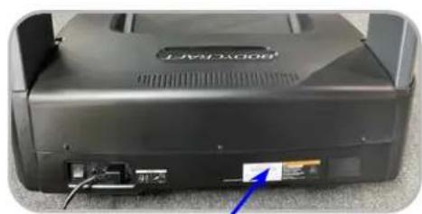
Base Serial Number: T802
Console Serial Number: ____
Purchased Date: ____ / ____ / ____
Dealer's Name:
Please register your products at:
https://www.bodycraft.com/product-registration/
natural_image
Close-up of a black electronic device with visible ports and a blue arrow pointing to a small component (no readable text or symbols)Base Serial Number
Owner's Manual
T802_v1.7

WWW.BODYCRAFT.COM

800-990-5556

SERVICE@BODYCRAFT.COM
This page intentionally left blank
Congratulations and Welcome to the BODYCRAFT Family
Thank you for selecting BODYCRAFT. Your choice reflects a wise investment in you and your facility. We hope you use it for many healthy years!
BODYCRAFT offers a complete array of high-quality fitness equipment. Please refer to our website at www.bodycraft.com to view more ways to enhance your lifestyle.
Your BODYCRAFT machine has all the quality and design elements to make your workout extremely efficient and comfortable. Your new unit is a serious cardio machine that will keep you motivated, challenged and within reach of your fitness goals. Strength & cardiovascular training is vital for all ages which will provide an effective workout, producing results that will encourage you to reach your fitness goals and maintain the body you have always wanted.
Spending 15 to 30 minutes a day, three times a week, is all you need to start seeing the benefits of a regular exercise program.
As a premium exercise equipment manufacturer, we are committed to your complete satisfaction. If you have questions, suggestions or find missing or damaged parts, we guarantee your complete satisfaction through our authorized dealer network or by contacting us directly. Please call your local dealer or BODYCRAFT.
BODYCRAFT (a division of Recreation Supply, Inc.)
7699 Green Meadows Dr.
Lewis Center, OH 43035
Phone: 800-990-5556 9 am - 5 pm EST Email: service@bodycraft.com
Proof of purchase must be supplied to validate warranty and the product must have been registered with BODYCRAFT via online at www.bodycraft.com or by calling 800-990-5556 or 740-965-2442 M-F 9 a.m. - 5 p.m. EST.
For parts orders, owner's manuals, software update files, exercise guides and contact information scan this QR code.
Or go to:
https://www.bodycraft.com/customer-support


Table of Contents

NOTE: When you have downloaded the Owner's Manual into a PDF reader, go directly to the desired page by touching any BLUE line in this Table of Contents.
Page
Product Safety Information
FCC Information 5
Product Safety 6 - 7
Power & Grounding Requirements
Grounding Instructions 8
Power Requirements 8
Product Overview
Product Overview Components & Tools for Assembly 9
Product Specifications ....10
Shipping Boxes and Pre-Assembly TIP 11
Assembly Parts & Hardware 12
How Assemble the Treadmill
Product Assembly Instructions ....13-24
How to Setup the Treadmill
Wall Outlet, Breaker and Extension Cords 24
Spacing Requirements 25
Leveling the Treadmill (Making it stable) 25
Running Belt Tension & Alignment 26
Installation Checklist 27
Operation Instructions
Console Options....28
Console Operating Instruction 29
Safety Key Clip & Tether 29

Energy
Energy Saving function: These treadmill consoles are equipped with a power saving function. This means after 10 minutes of inactivity, the treadmill will automatically power off. Press any key on the dashboard to wake up the console from power save mode.
Table of Contents

NOTE: When you have downloaded the Owner's Manual into a PDF reader, go directly to the desired page by touching any BLUE line in this Table of Contents.
Maintenance & Repairs
Cleaning your Treadmill 30
Preventive Maintenance....31
Troubleshooting & Error Codes on AC Motor Treadmill 32 - 33
Circuit Diagram 34
Detailed Parts Lists & Label Placements 35 - 36
Detailed Parts Exploded Views 37 - 41
Required Info BEFORE Initiating a Service Case ....42
Warranty & Contact Information
Product Warranty 43
Product Warranty Registration 44
Contact Us Information 45
FCC Information
Caution: Please note that changes or modifications not expressly approved by the party responsible for compliance could void the user's authority to operate the equipment.
This device complies with Part 15 of the FCC Rules. Operation is subject to the following two conditions:
(1) This device may not cause harmful interference, and (2) this device must accept any interference received, including interference that may cause undesired operation.
NOTE: This equipment has been tested and found to comply with the limits for a Class B digital device, pursuant to Part 15 of the FCC Rules. These limits are designed to provide reasonable protection against harmful interference in a residential installation. This equipment generates, uses and can radiate radio frequency energy and, if not installed and used in accordance with the instructions, may cause harmful interference to radio communications. However, there is no guarantee that interference will not occur in a particular installation. If this equipment does cause harmful interference to radio or television reception, which can be determined by turning the equipment off and on, the user is encouraged to try to correct the interference by one or more of the following measures:
Reorient or relocate the receiving antenna.
Increase the separation between the equipment and receiver.
Connect the equipment into an outlet on a circuit different from that to which the receiver is connected.
Consult the dealer or an experienced radio/TV technician for help.
FCC CAUTION: Changes or modifications not expressly approved by the party responsible for compliance could void the user's authority to operate this equipment.

There is a risk assumed by individuals who use this type of equipment. A moment's lack of attention can result in an accident, as can failure to observe certain simple safety precautions.
Read, study and understand the Assembly Instructions and all the warning labels on this product. Furthermore, it is recommended to familiarize yourself and others with the proper operation and workout recommendations for this BODYCRAFT product prior to use.
- Keep children under the age of 13 and pets away from the equipment at all times. Do not allow children and pets to use or play on the equipment. Keep children and pets away when it is in use.
- The treadmill is not intended for use by persons with reduced physical, sensory, or mental capabilities or lack of experience and knowledge, unless they have been given supervision or instruction concerning use of the treadmill by someone responsible for their safety.
- Wear the safety cord and clip all times while using the treadmill. Always stand on the side rails before the treadmill starts.
- Before beginning any exercise program on the treadmill, it is important to consult with your physician if you have any of the following: history of heart disease, high blood pressure, diabetes, chronic respiratory diseases, elevated cholesterol, if you smoke cigarettes or if you experience any other chronic diseases or physical complaints.
- If over the age of 35 or overweight or pregnant, consult with your physician before beginning any exercise program.
- If you experience dizziness, nausea, chest pains or other abnormal symptoms during exercise, stop the exercise session immediately. Consult your physician before continuing.
- Drink fluids if you exercise for twenty or more minutes on the treadmill.
- Always follow the console instructions for proper operation.
- Never operate your treadmill if it has a damaged cord or plug, or if it is not working properly. Contact your authorized BODYCRAFT fitness dealer for service and repair.
- Keep the power cord away from heated surfaces.
- Never insert any objects or body parts into openings.
- Keep hands and feet away from all moving parts.
- Use the handrails when getting on and off your treadmill.
- Check the power requirement for your unit to see if it matches your local power outlet.
- Do not operate the heart rate monitor transmitter together with an electrical heart pacemaker. The transmitter may cause electrical disturbances.
- Inspect this treadmill prior to exercising to ensure it is working properly. Always make sure all components are fastened securely.
- This treadmill is intended for indoor use. Do not place the unit outdoors or any damp or wet locations.

- Keep the treadmill away from walls to allow proper ventilation. Air should be able to circulate freely around the unit. Keep all air openings free of dirt and dust.
- Place the treadmill in an area that will meet minimum clearance requirements: Front 12" (.3m), Sides: 20" (.5m) & Back 79" (2m) and from any obstruction object while using the machine.
- Wear proper exercise clothing and shoes for your workout and avoid loose clothing. Never exercise in bare feet or socks; always wear correct footwear, such as running, walking, or cross-training shoes.
- Higher speed and higher incline is not for everyone. It is designed for occasional use of a skilled runner and may exceed many users' capabilities. Stop right away if you feel any discomfort. Never walk or jog or run backwards on the treadmill.
- Place your treadmill on a solid, level surface when it is in use. Adjust the levelers at the rear of the treadmill if necessary.
- Be careful to maintain your balance while using, mounting, dismounting, or assembling the equipment. Loss of balance may result in a fall and serious bodily injury. Use care when getting on or off the treadmill. When stepping on the running belt, always grasp the handrail and keep the initial speed at or below 1 mile per hour (mph).
- Make sure the running belt is at a complete stop before exiting the machine.
- Never leave the treadmill unattended when plugged in. Unplug from outlet when not in use, before putting on or taking off parts. When the treadmill is not in use, disconnect the treadmill by turning the power switch to the Off position, and then remove the power plug from the electrical outlet.
- Always attach the Safety key securely to your clothing when using the treadmill.
- Do not pull the treadmill by the power cord or use cord as a handle. Always use two hands to lift the treadmill and roll it on its front wheels.
- Keep the power cord away from heated surfaces.
- Keep the top side of the moving surface clean and dry or potential injury will occur.
- Read, understand, and test the emergency stop procedures before use.
- To ensure proper function of your treadmill, do not install attachments or accessories not provided or recommended by BODYCRAFT.
- This T800 Treadmill is intended for home use and light commercial, rental, or institutional setting. Use only for its intended purpose described in this manual.
- The T800 Treadmill user's weight is not to exceed 425 lbs (193 kgs).
Safety and Warning for a Treadmill - Grounding Instructions
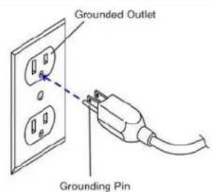
This product must be grounded. If the treadmill's electrical system should malfunction or breakdown, grounding provides a path of least resistance for electric current, reducing the risk of electric shock. This product is equipped with a cord having an equipment-grounding plug. The plug must be plugged into an appropriate outlet that is properly installed and grounded in accordance with all local codes and ordinances.

DANGER - Improper connection of the equipment-grounding conductor can result in a risk of electric shock. Check with a qualified electrician or serviceman if you are in doubt as to whether the product is properly grounded. Do not modify the plug provided with the product if it will not fit the outlet; have a proper outlet installed by a qualified electrician.
This product is for use on a nominal 120 volt wall circuit, and has a grounding plug that looks like the plug illustrated in the figure. Make sure that the product is connected to an outlet having the same configuration as the plug. No adapter should be used with this product.
Safety and Warning for a Treadmill - Power Requirements T800 (T801 & T802)
It is recommended that your treadmill be plugged into a Dedicated 120V/15A for home use (120V/20A for light applications). The treadmill must be connected to a grounded receptacle having the same configuration as the plug. Do not modify the plug provided with this product. If it will not fit the outlet, have a proper outlet installed by a qualified electrician.

natural_image
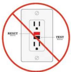
Electrical wiring setup with wires and components, no visible text or symbolsNOTE: DO NOT USE an GFCI wall outlet. A treadmill uses the ground on the outlet to disperse static electricity generated by it's belt, deck and motor design. Highly likely if using an GFCI outlet, it will trip the breaker and shut down the treadmill, potentially causing the treadmill's electronics failure or serious injury to the user.

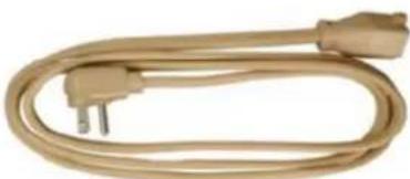
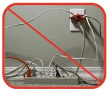
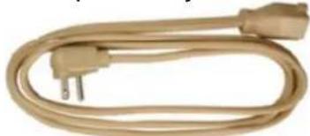
A power strip should never be used. Extension cords should be avoided, but we realize that in some cases an extension cord is needed. In this case, Appliance Grade extension cords are available at most hardware stores. Buy only the minimum length required; avoid anything longer than 6 feet. Try to find one made with 12 gauge wire (3-wire is required). Do not use an adapter with your treadmill.
To reduce the risk of electric shock, always unplug the treadmill from the electrical outlet before cleaning or lightning storms.
natural_image
Coiled beige electrical plug with two terminal connectors (no text or symbols visible)Product Overview Components and Tools for Assembly - T800 (T802)

THE FOLLOWING TOOLS ARE RECOMMENDED FOR EASIER ASSEMBLY:

ALLEN WRENCHES SET
(4mm to 10mm)

PHILLIPS SCREWDRIVER #2
w/ Magnetic TIP
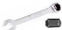
WRENCH & SOCKET
13mm 13mm
natural_image
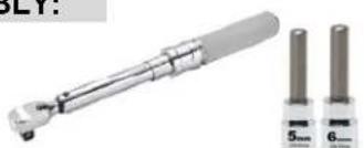
Two metallic tools with sizes labeled 5mm and 6mm, shown side by side (no text or symbols on the tools themselves)TORQUE WRENCH 3/8 DRIVE w/ 5mm & 6mm ALLENS
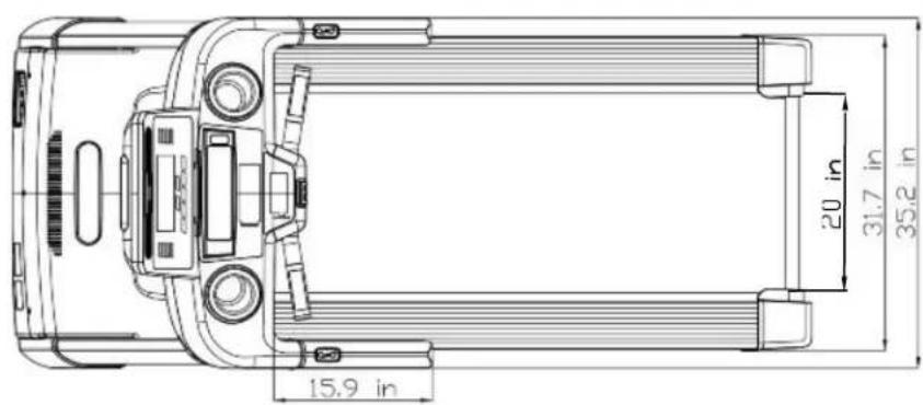
Product Specifications - T800 (T802)
RUNNING BELT: 20" W x 61" L x 2.0mm T
RUNNING DECK: 1" Thick Reversible Deck
HANDRAILS: 12.50" Custom Molded Soft Touch
DIMENSIONS: 80" L x 35" W x 59" H
WEIGHT: 280 lbs (Assembled)
MAX USER WEIGHT: 425 lbs

natural_image
Line drawing of a treadmill with control panel and display screen, showing measurement dimension (35.1 in) at bottom (no text or symbols on the device itself)

Shipping Boxes and Pre-Assembly Tip - T800 (T801 & T802)

Small Box 2 of 2
1 each @ 9 lbs
(T9LCD/T10TS)
or
1 each @ 10 lbs (T16TS)
19" × 6.25" × 5"
(Includes the console model that was ordered)

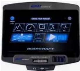
Note: Shown above with the upgraded 16TS console
Pre-Assembly TIP: Place all parts from the boxes in a cleared area and position them on the floor in front of you. Remove all packing materials from your area and place them back into the box. Do not dispose of the packing materials until assembly is completed.
Read each step carefully before beginning.
BODYCRAFT reserves the right to make improvements at any time which may affect color, parts, materials, size, weight, or any other aspect.

NOTE: Many images shown are GENERIC for the EXP Series Treadmills T1000 / T800 / T400 on multiple assembly STEPS.
STEP 1 - Upright Post-Right Wiring Connection
a. Lay the Upright Post - Right (050) next to the treadmill's Base Assembly (001-ASM) on its right side. See example pic. on Fig. 1.
b. Then connect the following cables from the Upright Tube - Right (050) to the Base Assembly (001-ASM):
i. Cable - Mid (#056 w/6pin) <<< --- >>> Cable - Lower (#032 w/6pin)
ii. Grounding Cable (#164 w/1pin) <<< --- >>> Grounding Cable (#165 w/1pin)

Fig. 1

NOTE: Confirm connections have no bent pins (Fig. 2) and are securely locked (Fig. 3) with a gentle

natural_image
Close-up of a damaged mechanical component with a red X mark overlay (no text or symbols on the object itself)Fig. 2
pull after connected.

natural_image
Close-up of a black plastic electronic component with multicolored wires, partially enclosed in a rounded square frame (no visible text or symbols)Fig. 3

Only loosely tighten ALL BOLTS until STEP 8
STEP 2 - Install Upright Post - Right
a. Attach the Upright Post -
Right (050) to the Base
Assembly (001-ASM) using
the following hardware:
i. Two Allen Head Bolts,
ii. Two Hex Head Bolts,
$$ \mathrm{M} 8 \times 7 0 \mathrm{mmL} (0 5 1) $$
$$ \mathrm{M} 8 \times 1 5 \mathrm{mmL(052)} $$
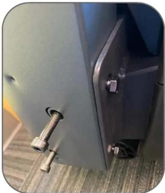
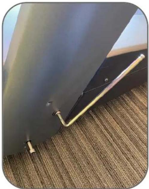
Note: See CAD image on right and both Fig 4 and Fig 5 for examples.
Recommended Tools:
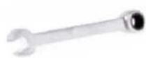
WRENCH
13mm

ALLEN WRENCH
6mm
natural_image
Close-up of a mechanical component with metallic pins and bolts, mounted on a textured floor (no visible text or symbols)Fig. 4 Fig. 5

CAUTION
Pinch Point
Keep hands clear of edges

TIP: Easier if installing first, the long Allen Head Bolts lightly by hand, then the Hex Head Bolts will line up better.
Then loosely thread in the rest of the way with the 6mm Allen Wrench and the 13mm Wrench.
natural_image
Close-up of a black metal hinge attached to a textured carpet, with a yellow metal rod inserted (no text or symbols visible)
Only loosely tighten ALL BOLTS until STEP 8
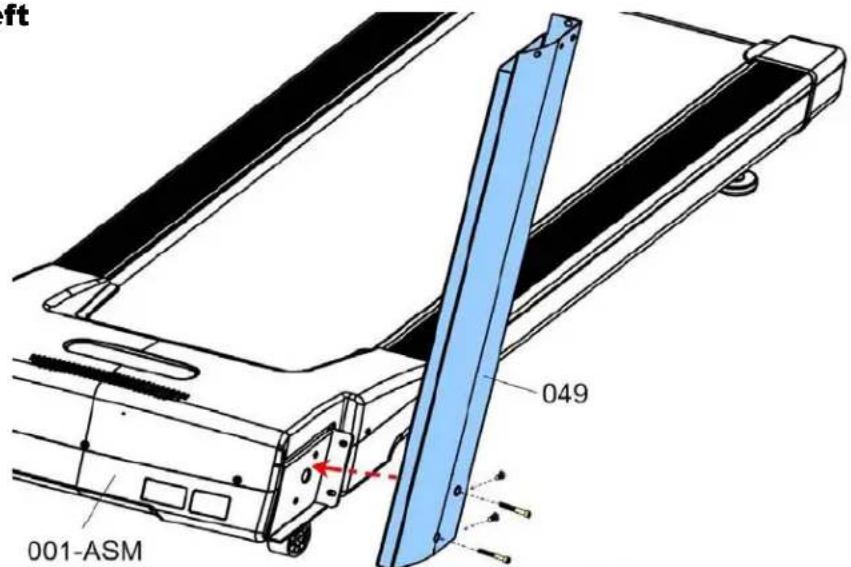
STEP 3 - Install Upright Post - Left
a. Attach the Upright Post - Left (049) to the Base Assembly (001-ASM) using the following hardware:
i. Two Allen Head Bolts, M8 x 70mm L (051)
ii. Two Hex Head Bolts, M8 x 15mm L (052)
Recommended Tools:

WRENCH
13mm
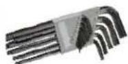
ALLEN WRENCH
6mm


STEP 4 – Prepare for the Dashboard Assembly
a. Confirm the two Cables are hanging out of the top of Upright Post - Right (050).
b. Confirm both Upright Posts - Left (049) and Right (050) have movement and the bolts ARE NOT fully tightened.
c. This slight movement is necessary for STEP 5 - STEP 8 assembly.
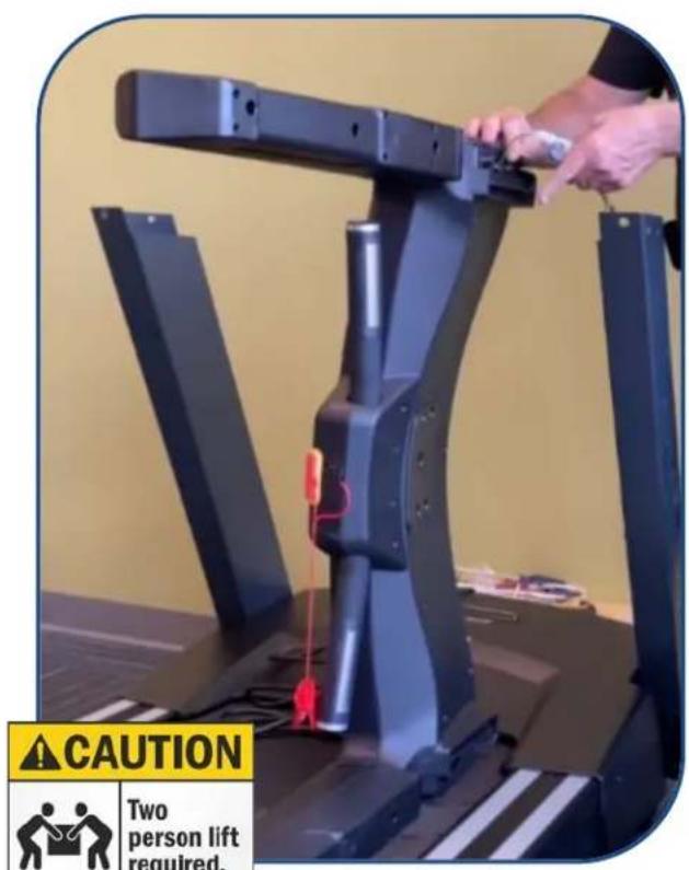
Fig. 6
c. After both cables are connected, confirm they are fully locked together. Then lift up the Dashboard Assembly and GENTLY slide into both the Right & Left Sides of the Upright Tubes. See pic on Fig. 7.
NOTE: Easier & SAFER for two people to perform this task. Pinched or severed cables during assembly is not covered under warranty.
Fig. 7

CAUTION
Pinch Point Keep hands clear of edges
STEP 5 – Installing the Dashboard Assembly
a. Gently lay the Left Side of the Dashboard Assembly (090-ASM) on the running belt area. See example pic. on Fig. 6.
b. Then connect the following cables from the Dashboard Assembly (090-ASM) - Right Side to the Upright Post - Right (050):
i. Cable - Upper (#132 w/6pin) <<< -- -- >>> Cable - Mid (#056 w/6pin) ii. Grounding Cable (#167 w/1pin) <<< -- -- >>> Grounding Cable (#164 w/1pin)


Only loosely tighten ALL BOLTS until STEP 8
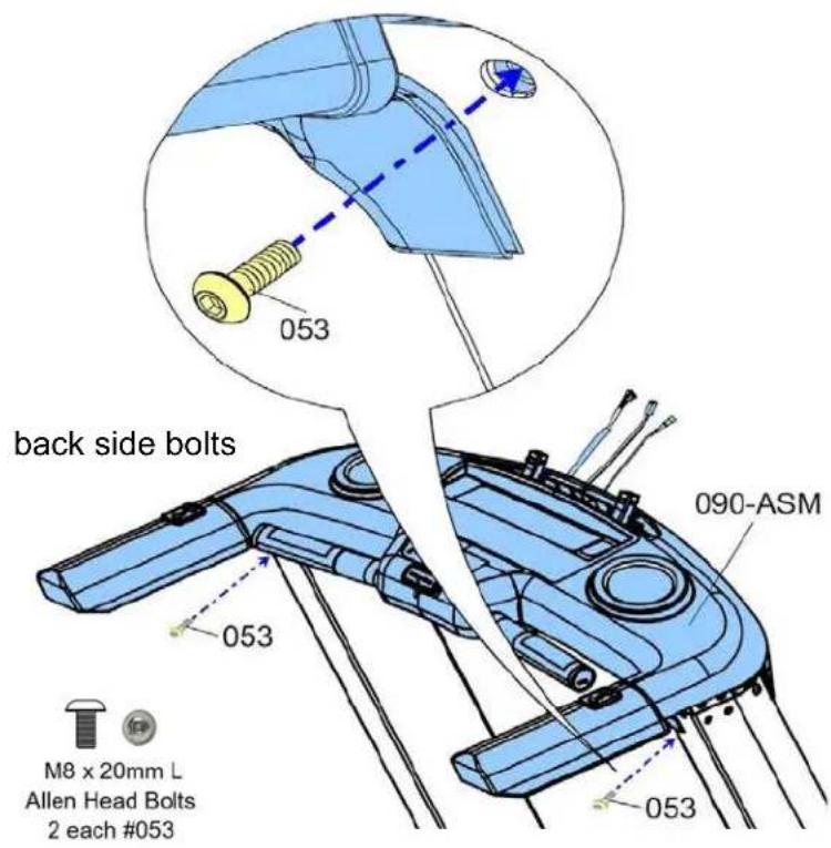
STEP 6 – Installing the Dashboard Assembly to the Upright Posts

natural_image
Close-up of hands using a screwdriver to adjust or install a mechanical component (no visible text or symbols)Fig. 8
TIP: Easier to line up the front and back bolts to the holes for STEP 6a thru STEP 6b, when using an #2 Phillips Screwdriver in the side holes to push up or down for alignments.
See Fig. 8 above.

a. Attach the Dashboard Assembly (090-ASM) to the Upright Posts (049 Left and 050 Right) using the following hardware:
i. Two Allen Head Bolts, M8 x 20mm L (053), back side ii. Two Allen Head Bolts, M8 x 20mm L (053), front side
Recommended Tool:

ALLEN WRENCH
6mm

Only loosely tighten ALL BOLTS until STEP 8
STEP 7 – Preparing to Fully Tighten the Upright Posts
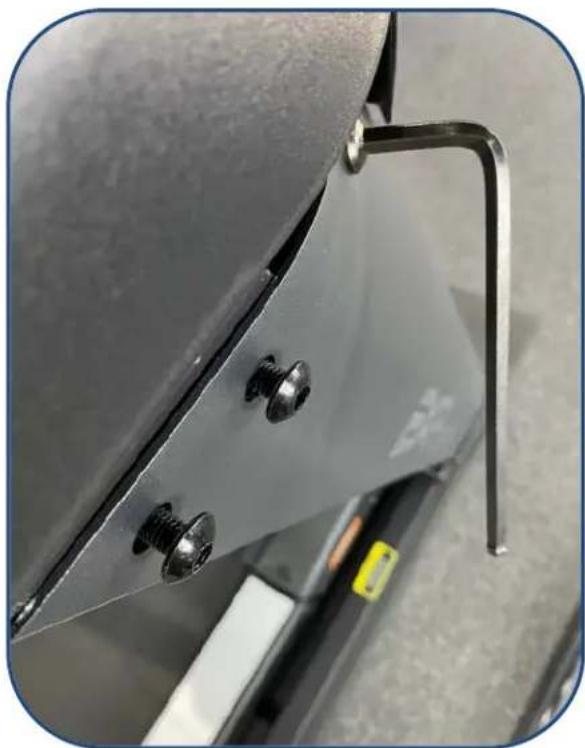
a. Before fully tightening to Torque Specs in STEP 8, gently hand screw in half-way, all 4 Allen Head Bolts, M8 x 20mm on both sides of the Upright Posts to the Base Frame Assembly (001-ASM) and the Dashboard Assembly (090-ASM), See Fig. 9 image.
b. Snug up both front and rear bolts with the 6mm Allen Wrench. This will ensure during the tightening to Torque Specs on the other bolts, the hole alignment to bolts will not go off when installing the plastic Handle Bar Covers both #055 & #054 during STEP 9a and Step 9b.
Note: Cross threaded bolts and/or stripping out the pre-threaded holes M8mm x 1.25p will not be covered under warranty due to installation alignments.
natural_image
Close-up of a metallic bracket with screws and a metal hinge, no visible text or symbolsFig. 9
natural_image
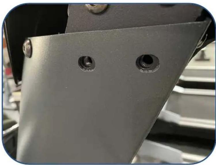
Close-up of a metallic mechanical component with two circular holes, no visible text or symbolsFig. 10
c. Then unscrew out the 2 each side bolts from Upright Post - Right (050) and 2 each side bolts from Upright Post - Left (049) before continuing to STEP 8. Double confirm the outer opening holes leave room for the bolt threads to line up with the inner threaded holes. See pic on Fig. 10.
Product Assembly

STEP 8 - "Torque Time"
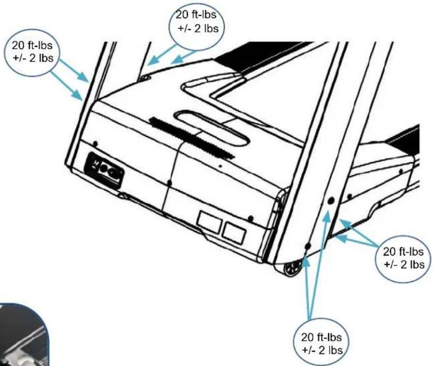
Tighten all Hex Bolts and Allen Head Bolts to the Recommended Torque Specs of 20 ft-lbs (+/- 2 lbs). These are from STEP 2 to STEP 7. See Fig. 11 as an example.
Recommended Tools:



natural_image
Close-up of a motorcycle leg with a digital pressure gauge and a 20.7 mm scale indicator (no visible text or symbols on the device itself)Fig. 11

Tighten Bolts at this time to the Recommended Torque Specs
Product Assembly
STEP 9 - Installing the Handlebar Covers - Right & Left
a. Attach the Handlebar Cover - Right (055) and the Handlebar Cover - Left (054) to the Dashboard Assembly (090-ASM) using the following hardware:
i. Two Allen Head Bolts, M8 x 20mm L (053), Right Cover
ii. Two Allen Head Bolts, M8 x 20mm L (053), Left Cover
Recommended Tool:

ALLEN WRENCH
6mm

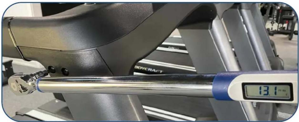
STEP 10 – “Torque Time” Tighten the Allen Head Bolts to the Recommended Torque Specs of 13 ft-lbs (+/- 1 lbs). See Fig. 12 as an example.
Fig. 12
natural_image
Close-up of a Body Gymnastics machine with a digital pressure gauge showing 13.1°F, no visible text or symbols on the device itself.STEP 11 – Installing the Upright Post Covers - Right & Left
a. Attach the Upright Post Cover - Right (048) to the Upright Post - Right (050) using the following hardware:
i. Two Screws M5 x 12mm L (028)
b. Then attach the Upright Post Cover - Left (047) to the Upright Post - Left (049) using the following hardware:
i. Two Screws M5 x 12mm L (028)


natural_image
Technical diagram of a curved mechanical component with dimension annotations (028), no readable text or symbols present.Recommended Tool:

PHILLIPS SCREWDRIVERS #2
w/ Magnetic TIP
NOTE: Double confirm the Screws are tightened down to withstand vigorous usage.
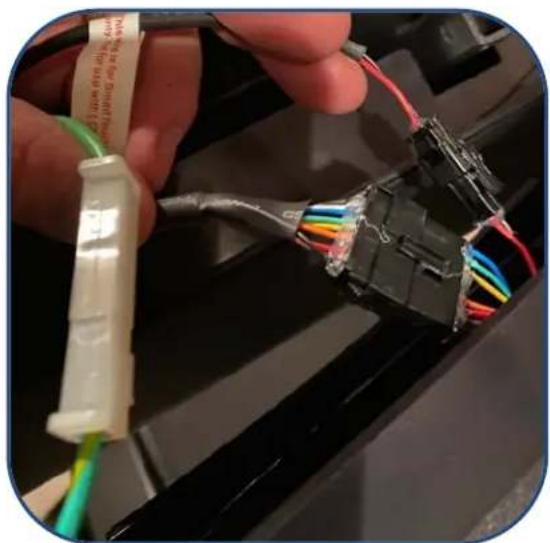
STEP 15 - Console Wiring to the Dashboard Assembly.
a. Connect the following cables from the Console (146) to the Dashboard Assembly (090-ASM):
i. 1st Cable - Break-Out Board to Console - Lower (#142 w/9pin) <<< --- >>> Cable - Main Console (#220 w/9pin)
ii. 2nd Cable - Break-Out Board to Console - Lower (#128 w/2pin) <<< --- >>> Cable - Power Console (#221 w/2pin)
NOTE: 2nd Cable is ONLY USED with Touch 16" & 10". NOT to be used with the 9" LCD consoles.
iii. 3rd Cable/Wire Grounding Cable (#166 w/ 1pin) <<< --- >>> Grounding Cable Console (#207 w/1pin)

natural_image
Close-up of a hand holding a black connector with multicolored wires, attached to a device (no visible text or symbols)Fig. 13
b. After all cables are connected, confirm they are fully locked together. Then GENTLY slide the console onto the U-Shaped tubes without damaging any cable or connections. See pic on Fig. 13.
NOTE: Easier & SAFER for two people to perform this task. Pinched or severed cables during assembly is not covered under warranty.
STEP 16 - Secure the Console to the Dashboard Assembly.
a. Attach the Console (146) to the Dashboard Assembly (090-ASM) using the following hardware:
i. Two Allen Head Bolts, M6 x 35mm L (114)
Recommended Tool:

ALLEN WRENCH
5mm

M6 x 35mm L
Allen Head Bolts
2 each # 114


natural_image
Close-up of a hand using a tool to adjust or install a body-crank exercise machine (no visible text or symbols)Fig. 14
b. Confirm the Console is completed seated down onto the Dashboard Assembly with all plastics flush against each other.
NOTE: This might take a bit of wiggling and double checking for any crushed cable in the way.
c. "Torque Time" - Tighten the two Allen Head Bolts to the Recommended Torque Specs of 13 ft-lbs (+/- 1 lbs).
See Fig. 14 on the left.

natural_image
Two laboratory tools: a vertical scale ruler and a horizontal tool with a handle, shown without any text or symbols.Product Assembly

STEP 17 - Power Cord
a. Confirm the Power Cord (156) is attached to the Base Assembly (001-ASM). See CAD image to left.
b. This should be secured from the Locking Screw-in Clip (144) to the AC Socket/Input Power (150). See Fig. 20 below using the pre-installed hardware:
i. Screw M4 x 12mm L (095)
Fig. 20

natural_image
Close-up of a black electronic device with a switch and cable (no visible text or symbols)Product Setup - Wall Outlet, Breaker and Extension Cords
It is recommended that your treadmill be plugged into a Dedicated 120V/15A for home use (120V/20A for light applications). The treadmill must be connected to a grounded receptacle having the same configuration as the plug. Do not modify the plug provided with this product. If it will not fit the outlet, have a proper outlet installed by a qualified electrician.
natural_image
Electrical wiring setup with wires and connectors, no visible text or symbolsNOTE: DO NOT USE an GFCI wall outlet. A treadmill uses the ground on the outlet to disperse static electricity generated by it's belt, deck and motor design. Highly likely if using an GFCI outlet, it will trip the breaker and shut down the treadmill, potentially causing the treadmill's electronics failure or serious injury to the user.


A power strip should never be used. Extension cords should be avoided, but we realize that in some cases an extension cord is needed. In this case, Appliance Grade extension cords are available at most hardware stores. Buy only the minimum length required; avoid anything longer than 6 feet. Try to find one made with 12 gauge wire (3-wire is required). Do not use an adapter with your treadmill.
To reduce the risk of electric shock, always unplug the treadmill from the electrical outlet before cleaning or lightning storms.
natural_image
Coiled beige electrical plug with two terminal leads (no text or symbols visible)Product Setup - Spacing Requirements
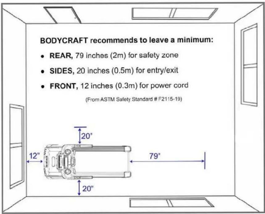
U.S. and other regions: The ASTM International (ASTM) F2115-19 Standard recommends the dimensions to be 1.64 ft. (.5 m) on each side of the treadmill and 6.5 ft. (2 m) behind the reward most portion of the usable moving surface or 6.5 ft. (2 m) behind the furthest rearward obstruction to emergency egress from the treadmill.
EU: The European EN ISO 20957 Safety Standard requires a 6.5 ft. (2m) minimum from the rear of the treadmill to any object or surface and at least as wide as the treadmill.
Product Setup - Leveling the Treadmill
Sometimes floor surfaces are not level or even. Once your treadmill is in the desired location, take the time to ensure that it is stable. All four contact points should make contact with the floor (2 wheels at the front and 2 adjustable rear stabilizers). If necessary, adjust the height of the rear stabilizers by turning it clockwise or counterclockwise to either lower or raise the machine. Test by walking or running the machine to ensure that the treadmill is not rocking on your floor. It must be level and stable to operate properly and eliminate any undue wear and tear on the treadmill or your floor.

In some cases you may need to purchase an optional mat that will also help level all 4 contact points. Mats will also help reduce noise and can help to protect most types of flooring. If you wish to purchase a mat, contact the dealer you purchased the treadmill from or contact BODYCRAFT.
Product Setup - Leveling, Running Belt Tension & Alignment

Follow these steps after the assembly STEPS to ensure proper function of your treadmill!
- If you are not comfortable performing these STEPS, please contact your local BODYCRAFT dealer or our customer support department to arrange a qualified technician to come to your home or commercial location.
T800 SERIES
STEP 1: Level the treadmill. Refer to the "Leveling the treadmill" procedure from earlier Product Setup pages for more details.

STEP 2: Next, adjust for Running Belt Tension. Stomp Test method: While straddling the Running Belt, with your feet on the Side Rails, start the treadmill to 2.5 mph / 4 kmh, then while holding on to the handrails, use your stronger foot only, stomp your foot down & forward to see if the Running Belt slips. If the belt does not slip, continue to STEP 3. If the belt slips, the adjustment screws must be tightened evenly both right & left sides in order to adjust the belt properly. The adjustment screws are located at the rear of the treadmill in the end caps (see figure below).
- Both rear roller adjustment screws should be tightened in a clockwise direction with a 6mm Hex Wrench.
- After each adjustment check the running belt for slipping after each adjustment. If the belt continues to slip, repeat this process until the belt stops slipping. Make sure to ONLY turn both adjustment screws 1/2 turn each time until the slipping stops. This will ensure that you do not over-tighten the rollers.
Over-tightening the rollers may cause serious damage to the treadmill
Once you have adjusted the tension, you need to do an Running Belt Alignment procedure in STEP 3.

STEP 3: Next, adjust for Running Belt Alignment. The Running Belt needs to be centered between the Side Rails with the same amount of space from both Left & Right edges of the Running Belt to each Side Rail.
○ Start the treadmill and run it at 5 mph / 8 km h for 1 to 2 minutes to insure the belt will stay in the center.
- If the Running Belt is not centered, loosen the adjustment screw on the opposite side (where it has more space), turning it counterclockwise 1/4 turn. Wait 1 min to confirm the Running Belt is now centered.
- Repeat the procedure if necessary ONLY doing a 1/4 turn per adjustment.

Watch STEP 3 on YouTube

STEP 4: Double confirm the Running Belt tension is still correct by simulating a Max Weight User. Simply start walking on the treadmill at 3 mph . Then hold on the front handrails (with BOTH HANDS) and apply as much downward and forward pressure with your feet while walking. Your feet should be moved back with the motion of the Running Belt without any slipping. If there is any slipping, then go back to STEP 2.
v1.2
Installation Checklist
Assembly and Set-Up
Confirmed
| Confirm all parts are assembled |
| Confirm there are no pinched console/upright wires |
| Confirm all hardware is tightened down |
| Check Base Assembly is level (no movement) |
| Check if Running Belt is tensioned (no slipping) |
| Check if Running Belt is centered |
Confirm space requirements are met:
| - 2 ft. front and sides of treadmill |
| - 6 1/2 ft. rear of treadmill (emergency exit) |
| Confirm power requirements are met: |
| - 120v/15amp dedicated per TM (home unit) |
| - 120v/20amp dedicated per TM (com. unit) |
| - Any extension cords max 6' long w/ 12 gauge wire |
| - Electrical outlet is non-GFCI w/ confirmed ground |
| Confirm Power Cord location is protected from damage |
Calibration:
Confirmed
| Calibration was completed & confirmed good |
Console:
| Console has newest software updates |
| Touch Screen 10", 16" or 19" has updated Apps |
Final Checks:
| Treadmill has been tested & fully functioning |
| Gave Owner's Manual to the customer |
| Answered any & all customer's questions |
Service Policy:
| How to contact Customer Support |
| Warranty length & coverage |
| What warranty does not cover |
| How to find the serial number |
| How to find an error code (if applicable) |
Important Safety Information:
| NOTE: Never leave unattended children around a treadmill when plugged into the Wall Outlet & the Safety Key Inserted. |
BODYCRAFT
Recommended Maintenance (refer to owner's manual)*
Confirmed
| Cleaning products for use on Base & Upright Assembly |
| Cleaning products for use on Dashboard Assembly |
| Cleaning products for use on Console |
| Running Belt and Deck is cleaned & lubricated as needed |
| Under Treadmill & Side Rails are cleaned as needed |
| Under Motor Hood is cleaned as needed: |
| - All dirt is vacuumed and surfaces cleaned |
| - Motor vents and electronics are cleaned |
| - DC Motor brushes and commutator are cleaned (T400/T800) |
* Maintenance must be performed when needed, to maintain warranty
BODYCRAFT
| 7699 Green Meadows Dr North |
| Lewis Center, OH 43035 |
| Product Support - Treadmills: 1-800-990-5556 x 406 |
| Email questions or parts ordering: service@bodycraft.com |
Customer's Name:
| (Point of Contact for Commercial Facility): | ||
| Address: | ||
| Address Line 2: | ||
| City: | ||
| State: | Zip: | P |
Email:
| Type of Facility: |
| Location of Equipment: |
Dealer Name:
| Point of Contact: | ||
| Address: | ||
| Address Line 2: | ||
| City: | ||
| State: | Zip: | Phone: |
| Email: | ||
Model & Serial Numbers Installed:
| Model # | Serial # |
| Model # | Serial # |
| Model # | Serial # |
| Installer's Name: | Notes: | |
| Installer's Signature: | Date: | |
| Customer's Signature: | Date: | |
EXP SERIES TREADMILLS
v1.6
Console Options
16" SmartTouch Console 10" Smart Touch Console 9" LCD Console
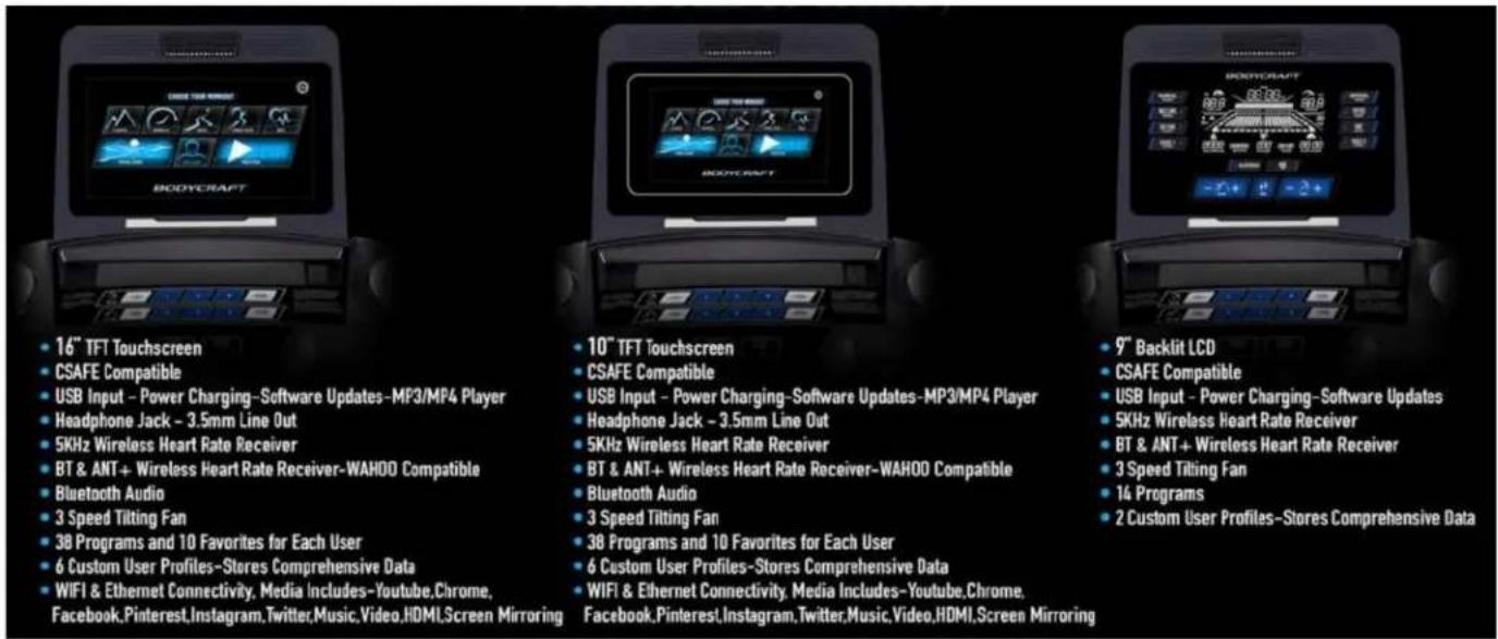
• 16" TFT Touchscreen
• CSAFE Compatible
USB Input - Power Charging-Software Updates-MP3/MP4 Player
Headphone Jack - 3.5mm Line Out
- 5KHz Wireless Heart Rate Receiver
BT & ANT+ Wireless Heart Rate Receiver-WAHOO Compatible
Bluetooth Audio
3 Speed Tilting Fan
38 Programs and 10 Favorites for Each User
6 Custom User Profiles-Stores Comprehensive Data
- WIFI & Ethernet Connectivity, Media Includes-Youtube,Chrome, Facebook,Pinterest,Instagram,Twitter,Music,Video,HDMI,Screen Mirroring
- 10" TFT Touchscreen
CSAFE Compatible
USB Input - Power Charging-Software Updates-MP3/MP4 Player
Headphone Jack - 3.5mm Line Out
- 5KHz Wireless Heart Rate Receiver
BT & ANT+ Wireless Heart Rate Receiver-WAHOO Compatible
Bluetooth Audio
3 Speed Tilting Fan
38 Programs and 10 Favorites for Each User
6 Custom User Profiles-Stores Comprehensive Data
WIFI & Ethernet Connectivity. Media Includes-Youtube,Chrome,
Facebook, Pinterest, Instagram, Twitter, Music, Video, HDMI, Screen Mirroring
9" Backlit LCD
CSAFE Compatible
USB Input - Power Charging-Software Updates
5KHz Wireless Heart Rate Receiver
BT & ANT+ Wireless Heart Rate Receiver
3 Speed Tilting Fan
14 Programs
2 Custom User Profiles-Stores Comprehensive Data
www.bodycraft.com/16TS-qr.html

www.bodycraft.com/10TS-qr.html

www.bodycraft.com/9LCD-qr.html


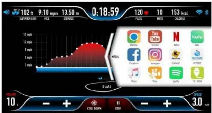
line
| Time | Value | |---|---| | 0:18:59 | 120 | | 1:00:00 | 10 | | 1:30:00 | 153 | | 2:00:00 | 153 kcal | | 3:00:00 | 153 kcal | | 4:00:00 | 153 kcal | | 5:00:00 | 153 kcal | | 6:00:00 | 153 kcal | | 7:00:00 | 153 kcal | | 8:00:00 | 153 kcal | | 9:00:00 | 153 kcal | | 10:00:00 | 153 kcal | | 11:00:00 | 153 kcal | | 12:00:00 | 153 kcal | | 13:00:00 | 153 kcal | | 14:00:00 | 153 kcal | | 15:00:00 | 153 kcal | | 16:00:00 | 153 kcal | | 17:00:00 | 153 kcal | | 18:00:00 | 153 kcal | | 19:00:00 | 153 kcal | | 20:00:00 | 153 kcal | | 21:00:00 | 153 kcal | | 22:00:00 | 153 kcal | | 23:00:00 | 153 kcal | | 24:00:00 | 153 kcal |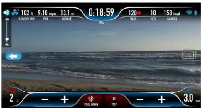
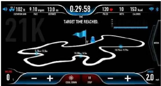
Console Operations Instructions - T800 (T801 & T802)
Please read the console operational instructions thoroughly and get familiar with the console layout.
Practice using this console before you start to get a better understanding of the functions. Below are the console layout and detailed operational instructions.
To power up the treadmill, locate the power cord attached to the front of the treadmill and plug it into a Dedicated 120V/15A for home use (120V/20A for Light Commercial applications) with a grounded wall outlet. Turn on the power switch to wake up the treadmill and go into the idle mode.
Always turn off the treadmill after hours or when not in use.
At Installation: The console needs to be paired with the treadmill product model correctly to ensure smooth operation. When the console is powered on the first time, it needs to be calibrated. Please follow the message window prompts to calibrate before use.

Safety Key Clip & Tether
Your treadmill will not start unless the safety key is placed on the proper location of treadmill console.
Attach the safety key clip properly onto your clothes before operating treadmill. In case of an emergency, pull the safety key off the treadmill, it will cut off the power to the console and stop the treadmill immediately. Place the safety key back in place, and the treadmill will resume back to idle mode. Contact your dealer for a safety key replacement if you do not have one.
CAUTION: Do not use any acidic cleaners. Doing so will discolor the plastics, painted surfaces and powder coatings. Never pour water or spray liquids on any part of the item.
- Turn off and unplug the treadmill power cord from the wall before using any cleaning product.
- ONLY APPLY CLEANER ON A CLOTH then use cloth to clean the unit.
- DO NOT spray cleaner directly on any surface of the Treadmill.
- We recommend that you clean the treadmill after each exercise session. To remove sweat, dust and dirt, wipe all exposed surfaces with slightly damp soft cloth only, never use solvents.
- Clean with mild soap and water based cleaners only.
- Always keep console and electrical parts clean and dry.
- Wipe or vacuum dust or other objects that may have accumulated underneath the treadmill.
- Never apply cleaning solution under running belt.
- Confirm running belt & siderails are dry from any accidental fluids spilling or overspray.
• DO NOT USE ABRASIVE CLEANING SCRUBBING PADS.
• DO NOT USE AMMONIA CLEANERS.
• DO NOT USE CITRUS CLEANERS
A. Only use a CLEAN & DRY Microfiber Cloth
B. If that is not enough, dampen the Microfiber Cloth with filtered water.
C. If heavy cleaning is required, use equal parts white vinegar and filtered water, applying ONLY onto a Microfiber Cloth. Be careful, too strong a solution can damage the screen.
D. Finish with a CLEAN and DRY MicroFiber Cloth.

natural_image
Close-up of a slice of black gelatin on a white plate with yellow topping, no text or symbols visibleThe following is RECOMMENDED for cleaning supplies:

MILD CLEANING
SOLUTION

natural_image
Two white fabric or towel sheets, folded together (no text or symbols visible)100% COTTON CLEANING CLOTHS
TIP ON FRAME ONLY: For extra protection from fingerprints, sweat stains or just plain dirt, apply an automotive grade cleaner wax at Installation and bi-annually. Also makes future cleaning easier.

(Do Not Use on Running Belt, Side Rails, Handlebar, HR Grips, any Plastic or Console Glass)
Preventive Maintenance - T800 (T801- T802)
Preventive Maintenance is the responsibility of the owner and not covered under warranty.
(Example of changing oil and rotating tires on new car.)
To maximize the life of your treadmill, and minimize downtime, all BODYCRAFT equipment requires regular cleaning and maintenance performed on a scheduled basis. Always unplug the power cord from the wall before servicing near potential moving parts or under the hood. ONLY qualified service professionals or BODYCRAFT dealers should remove the motor hood.
Daily Maintenance Items
- Check the Emergency Stop Key and tether cord for proper operation. Replace or repair if damaged.
- Check that the Power Cord is free from under the treadmill and shows no signs of damage. Inspect the Wall Plug End, especially the grounding pin. Replace if showing any signs of damage.
Weekly Maintenance Items
- Clean entire machine using water and mild detergent (cleaning agents should be alcohol and ammonia free), including console, handlebar / grip area and running belt.

natural_image
Yellow and black industrial vacuum cleaner with red handle and paintbrush (no visible text or symbols)Monthly Maintenance Items
• Vacuum under treadmill and wipe off all dirt around rollers & belt/deck areas.
- Inspect hand grip areas, Emergency Stop tether cord and all keypads for operation.
- Check running belt for proper tension, adjust if needed. It is especially important to check the running belt for tension after the first 30 days of usage. All new belts stretch and slippage can occur.
- Check the console for the software update/app update. Then Power Cycling (turning the power off at the treadmill switch, waiting 1 min then turning back on) is critical to the health of the console allowing to reset and refresh.
Quarterly / Semi-Annual Maintenance Items
- Unplug the power cord from the wall, then remove the front plastic cover, vacuum entire inside area of the machine focusing on the motor vents, motor control fan & electronics. NOTE: Be careful around any wires & all connections.
- Check drive belt for visible wear, i.e., cracking, tears, etc. The belt should be replaced if there are any visible signs of damage. Proper alignment of the pulley needs to be confirmed.
- Unplug the power cord from the wall, clean between belt and deck with a large towel.
- Due to running belts wearing differently in various environments, perform an amp draw test while running at 5 mph. If average is higher than 9 amps, lube deck with BODYCRAFT Silicone Lubricant 8-10 mL per side, then retest.
NOTE: Older version Silver Side Step Rails in image below

natural_image
Person standing on a treadmill with legs extended, wearing athletic shoes (no visible text or symbols)Annual Maintenance Items
- Unplug the power cord from the wall, inspect the underside of the running belt for damage - checking /cracking, glazed surface.
- If the running belt has damage or excessive wear verified by BODYCRAFT Service Department, then replace at the same time the running deck (if both sides have been used) with a Genuine BODYCRAFT replacement part.
- During normal operating conditions, after inspection & cleaning has been done on a routine basis (based on usage), the running belt and deck replacement should be done ONLY after higher Amp reading have been verified from a dedicated wall outlet and BodyCraft approved service provider.
- Lubricate incline motor screw (Recommend using a Super Lube branded grease with PTFE {Teflon} additive). Start the unit and raise Incline settings to maximum height. Turn power switch off at front of the machine to prevent it from lowering accidentally. 31
Troubleshooting & Error Codes on DC Motor Treadmill - Basics 1 of 2
This troubleshooting guide is intended to assist diagnostics only and is not all inclusive. Technical specifications, error codes and programming are subject to change without notice.
BODYCRAFT accepts no liability for any damage or loss suffered by persons who rely wholly or in part on any description or statement contained within this manual.
For any questions or additional help, contact the BODYCRAFT Customer Support at 800-990-5556 9 am - 5 pm EST or Email: service@bodycraft.com for assistance with troubleshooting and diagnostics.
| Malfunction | Possible Cause | Corrective Action |
| No Power | Unit turned off. | Verify the On/Off switch is at the ON position. |
| Damaged power cord. | Replace power cord. | |
| Power cord not fully seated in socket or wall outlet. | Inspect power connection at the unit and outlet. | |
| No power at outlet. | Using a voltmeter verify power 120v at the wall outlet. | |
| Tripped circuit breaker or GFCI. | The location of the circuit breaker is next to the On/Off switch.Verify the circuit breaker is not open. If the breaker is open, reset.- Confirm breaker is a non-GFCI circuit. A treadmill motor's frequency Does Not Work properly on GFCI protected circuits.Newer AFCI/GFCI wall circuits have the additional needed frequency protection to work with home treadmills. | |
| Unit resets or pauses randomly | Damaged power cord. | Replace the power cord. |
| Power cord not fully seated in socket. | Inspect power connection at the unit and wall outlet. | |
| Safety e-stop key not fully engaged. | Re-engage the safety/e-stop key to the console. | |
| Insufficient power. | Verify output voltage from Dedicated 120v/15amp (20amp commercial use) wall outlet with a voltmeter. | |
| Error code is displayed on the console. | Contact BODYCRAFT Customer Support 800-990-55569 am - 5 pm EST or Email: service@bodycraft.com | |
| Pinched or loose main communication cable. | ||
| Walking belt is off center | Uneven floor. | - Adjust treadmill with rear leveling feet.Go to: Running Belt Alignment page for detailed instructions. |
| Adjust belt tracking. | Go to: Centering the Running Belt page for detailed instructions. | |
| Walking belt hesitates or slips when stepping | Adjust belt tension. | Go to: Tensioning the Running Belt page for detailed instructions. |
| Lubricate running belt. | Go to: Treadmill Lubrication page for detailed instructions. | |
| Rubbing sound from treadmill when in operation | Walking belt is rubbing a straddle cover. | Adjust belt tracking go to page 17: Belt Tension and Alignment Adjustment. |
| Foreign objects may be stuck under the walking belt. | Inspect under the unit. Remove any object that may be under the unit. | |
| Foreign object may be stuck in motor compartment. | Contact BODYCRAFT Customer Support 800-990-55569 am - 5 pm EST or Email: service@bodycraft.com | |
| Roller bearings may be damaged | ||
| Drive motor may be damaged. | ||
| Drive belt may be misaligned. |
Troubleshooting & Error Codes on DC Motor Treadmill - Basics 2 of 2
| Malfunction | Possible Cause | Corrective Action |
| Heart rate is displaying erratically or not displaying | Transmitter belt contacts are not Making good contact with the skin. | Re-adjust the transmitter belt so that it is in full contact with the skin. |
| Contacts on the transmitter belt are not moist. | Moisten the contacts on the transmitter belt. | |
| Transmitter belt is not within 3feet (1 meter) of the heart rate receiver. | Adjust your position on the belt so that you are within 3foot (1 meter) of the console. | |
| The battery inside the transmitter belt is low or bad. | Replace the transmitter belt with a compatible transmitter belt. | |
| Another user wearing a compatible transmitter strap is within 3 foot (1 meter) of the unit. | Move the units so that there is more space in-between units. | |
| Environmental interference from high voltage power lines. | Move the unit to another position within the room or move the cause of the interference until heartrate reading are stable. If the probable source of interference is plugged into the same outlet move the suspect source to another outlet. | |
| Environmental interference from computers. | ||
| Environmental interference from motor driven appliances. | ||
| Environmental interference from cell or cordless phones. | ||
| Environmental interference from Wi-Fi router. |
| Error Code for DC Motor Treadmill | Definition | Possible Cause | Corrective Action |
| E-1 | Current Overload / Overheating / Protection | Belt and deck may require lubricant or Belt and deck may be worn excessively | - Go to: Treadmill Lubrication- If not fixed after lubrication procedure, then Contact BODYCRAFT Customer Support |
| E-2 | No Speed Signal (During Calibration Mode ONLY) | Controller is not receiving the speed signal | - Check wire harness for damage or completely connected at each connection point then recalibrate. - If continues then contact BODYCRAFT Customer Support |
| E-5 | Low AC Voltage | - Unstable Voltage input.- Too many machines on one circuit | - Turn off all machines in the same room.- Run one treadmill for 5-10 mins while heavy running.- Confirm no extension cords & Dedicated 120v/15amp (20amp commercial use) circuit per treadmill. |
| E-6 | High AC Voltage | ||
| E-10 | Incline Error | - Bad connection with wire harness at connections.- Need recalibration. | - Check wire harness for damage or completely connected at each connection point.- Recalibration procedure needed. |
| E-11 | |||
| E-22 | No communication between Breakout Board and Inverter | - Cable connection on fully connected or damaged cable.- The Breakout Board has malfunctioned. | - Double check all connections for bent pins or not fully clipped.- Check for damaged cable during installation and replace if necessary.- Replace Breakout Board if other actions are taken. |
| E-23 | |||
| E-88 | Console EEPROM failure | Console display has malfunctioned. | Turn off & wait 5 mins. Turn back on- If still E-21, replace the console. |
Lube icon: When the lube icon comes on, means the treadmill is due for lubrication maintenance. Please follow the owner's manual lubrication procedure to lubricate the tread/deck. AFTER the lubrication procedure is complete:
- 9" LCD: Press & hold "STOP" key during idle mode for a few seconds to turn the LUBE icon off for the.
- 16" & 10" Touch Screen: Follow the Reset prompts on the console.
Treadmill Circuit Diagram
T800 (T801 & T802)

flowchart
graph TD
    subgraph Upper_Trafficial_Uptress
        A["CONSOLE #146"] --> B["9 PIN"]
        A --> C["2 PIN"]
        A --> D["1 PIN"]
        E["GROUND WIRE - #167, 1 PIN (600mm L)"] --> F["1 PIN"]
        G["CABLE-UPPER (12 VDC) #132, 6 PIN @ 600 mm L"] --> H["6 PIN"]
        I["Break-OUT BOARD AC00410 #141"] --> J["JK5"]
        K["WIRELESS-5K HEART-RATE RECEIVER #143"] --> L["3 PIN"]
        M["SPEED KEY in RT ARM #160"] --> N["INCLINE KEY in LT ARM #100"]
        O["START/STOP KEYS #134"] --> P["QUICK KEYS SPEED/INCLINE #138"]
        Q["SAFETY KEY #115"] --> R["INTISTATIC BOARD #162"]
        S["MINISTER #107"] --> T["HANDORIP HEART-RATE SENSOR (Rt Side)"]
    end

    subgraph Base_Traffic_Autress
        U["A"] --> V["JK1"]
        U --> W["JK2"]
        U --> X["JK3"]
        Y["B"] --> Z["JK4"]
        Y --> AA["JK5"]
        AB["K"] --> AC["JK6"]
        AD["K"] --> AE["JK7"]
        AF["K"] --> AG["JK8"]
        AH["K"] --> AI["JK9"]
        AJ["K"] --> AK["JK10"]
        AL["K"] --> AM["JK11"]
        AN["K"] --> AO["K12"]
        AP["K"] --> AQ["K13"]
        AR["K"] --> AS["K14"]
        AT["K"] --> AU["K15"]
        AV["K"] --> AW["K16"]
        AX["K"] --> AY["K17"]
        AZ["K"] --> BA["K18"]
        BB["K"] --> BC["K19"]
        BD["K"] --> BE["K20"]
        BF["K"] --> BG["K21"]
        BH["K"] --> BI["K22"]
        BJ["K"] --> BK["K23"]
        BL["K"] --> BLA["K24"]
        BM["K"] --> BN["K25"]
        BO["K"] --> BP["K26"]
        BQ["K"] --> BQ1["K27"]
        CA["K"] --> CA1["K28"]
        CB["K"] --> CB1["K29"]
        CC["K"] --> CC1["K30"]
        DD["K"] --> DD1["K31"]
        DE["K"] --> DE1["K32"]
        DF["K"] --> DF1["K33"]
        DG["K"] --> DG1["K34"]
        DH["K"] --> DH1["K35"]
    end

    subgraph Bottom_Bridge_Drivering
        BI["SHORT STOP KEY #134"] --> BJ["SHORT STOP KEY #134"]
        BK["QUICK KEYS SPEED/INCLINE #138"] --> BL["QUICK KEYS SPEED/INCLINE #138"]
        BM["SAFETY KEY #115"] --> BN["SAFETY KEY #115"]
    end

    subgraph Base_Control_Bridge_Drivering
        BS["Lower Control Board for DC Motor #35"] --> BT["RED WIRE (#154, 100mm L)"]
        BU["Line Filter (EMI) #37"] --> BV["Bus WIRE (10 LAC) UP, red wire, black wire, black wire, black wire, black wire, black wire, black wire, black wire, black wire, black wire, black wire, black wire, black wire, black wire, black wire, black wire, black wire, black wire, black wire, black wire, black wire, black wire, black wire, black wire, black wire, black wire, black wire, black wire, black wire, black wire, black wire, black wire, black wire, black wire, black wires, black wires, black wires, black wires, black wires, black wires, black wires, black wires, black wires, black wires, black wires, black wires, black wires, black wires, black wires, black wires, black wires, black wires, black wires, black wires, black wires, black wires, black wires, black wires, black wires, black wires, black wires, black wires, black wires, black wires, black wires, Black wires, black wires, black wires, black wires, black wires, black wires, Black wires, Black wires, Black wires, Black wires, Black wires, Black wires, Black wires, Black wires, Black wires, Black wires, Black wires, Black wires, Black wires, Black wires, Black wires, Black wires, Black wires, Black wires, Black wires, Black wires, Black wires, Black wires, Black wires, Black wires, Black wires, Black wires, Black wires, Black wires, Black wires, Black wires, Black wires, Black wires, Black wires, Black lines<br>    end<br><br>    subgraph Top_Bridge_Drivering<br>        PC[CABLE-MIDDLE (12 VDC) #56.6 PIN @ 1.200mm L"] --> PCB["CABLE-MIDDLE (12 VDC) #56.6 PIN @ 1.200mm L"]
    end

    subgraph Bottom_Control_Bridge_Drivering
        PCC["CABLE-UPPER (12 VDC) #132.6 PIN @ 600 mm L"] --> PCD["CABLE-UPPER (12 VDC) #132.6 PIN @ 600 mm L"]
    end

    subgraph Base_Control_Bridge_Drivering
        PCE["CABLE-UPPER (12 VDC) #143.3 PIN @ 500mm L"] --> PCF["CABLE-UPPER (12 VDC) #143.3 PIN @ 500mm L"]
    end

    subgraph Top_Light_Autress
        PCG["CABLE-LOWER (12 VDC) #32.6 PIN @ 450mm L"] --> PCH["CABLE-LOWER (12 VDC) #32.6 PIN @ 450mm L"]
    end

    subgraph Bottom_Light_Bridge_Autress
        PCI["CABLE-LOWER (12 VDC) #32.6 PIN @ 450mm L"] --> PCJ["CABLE-LOWER (12 VDC) #32.6 PIN @ 450mm L"]
    end

    subgraph Base_Control_Bridge_Bridge_Autress
        PCK["CABLE-LOWER (12 VDC) #32.6 PIN @ 450mm L"] --> PCL["CABLE-LOWER (12 VDC) #32.6 PIN @ 450mm L"]
    end

    subgraph Bottom_Control_Bridge_Bridge_Bridge_Autress
        PCM["CABLE-LOWER (12 VDC) #32.6 PIN @ 450mm L"] --> PCN["CABLE-LOWER (12 VDC) #32.6 PIN @ 450mm L"]
    end

    subgraph Base_Control_Bridge_Bridge_Bridge_Bridge_Autress
        PCO["CABLE-LOWER (12 VDC) #32.6 PIN @ 450mm L"] --> PCP["CABLE-LOWER (12 VDC) #32.6 PIN @ 450mm L"]
    end

    subgraph Bottom_Light_Autress
        PCQ["CABLE-LOWER (12 VDC) #32.6 PIN @ 450mm L"] --> PCR["CABLE-LOWER (12 VDC) #32.6 PIN @ 450mm L"]
    end

    subgraph Bottom_Light_Bridge_Bridge_Bridge_Bridge_Autress
        PCS["CABLE-LOWER (12 VDC) #32.6 PIN @ 450mm L"] --> PCT["CABLE-LOWER (12 VDC) #32.6 PIN @ 450mm L"]
    end

    subgraph Base_Control_Bridge_Bridge_Bridge_Bridge_Autress
        PCU["CABLE-LOWER (12 VDC) #32.6 PIN @ 450mm L"] --> PCV["CABLE-LOWER (12 VDC) #32.6 PIN @ 450mm L"]
    end

    subgraph Bottom_Light_Credit_Bridge_Bridge_Bridge_Bridge_Autress
        PCW["CABLE-LOWER (12 VDC) #32.6 PIN @ 450mm L"] --> PCX["CABLE-LOWER (12 VDC) #32.6 PIN @ 450mm L"]
    end

    subgraph Bottom_Light_Bridge_Bridge_Bridge_Bridge_Autress
        PCY["CABLE-LOWER (12 VDC) #32.6 PIN @ 450mm L"] --> PCZ["CABLE-LOWER (12 VDC) #32.6 PIN @ 450mm L"]
    end

    subgraph Base_Light_Credit_Bridge_Bridge_Bridge_Bridge_Autress
        PCWCC["CABLE-LOWER (12 VDC) #32.6 PIN @ 450mm L"] --> PCXCC["CABLE-LOWER (12 VDC) #32.6 PIN @ 450mm L"]
    end

    subgraph Bottom_Light_Bridge_Bridge_Bridge_Bridge_Autress
        PCYCC["CABLE-LOWER (12 VDC) #32.6 PIN @ 450mm L"] --> PCXCC["CABLE-LOWER (12 VDC) #32.6 PIN @ 450mm L"]
    end

    subgraph Base_Light_Bridge_Bridge_Bridge_Bridge_Autress
        PCXCC["CABLE-LOWER (12 VDC) #32.6 PIN @ 450mm L"] --> PCXCC["CABLE-LOWER (12 VDC) #32.6 PIN @ 450mm L"]
    end

    subgraph Bottom_Light_Credit_Bridge_Bridge_Bridge_Bridge_Autress
        PCXCC["CABLE-LOWER (12 VDC) #32.6 PIN @ 450mm L"] --> PCXCC["CABLE-LOWER (12 VDC) #32.6 PIN @ 450mm L"]
    end

    subgraph Bottom_Light_Bridge_Bridge_Bridge_Bridge_Autress
        PCXCC["CABLE-LOWER (12 VDC) #32.6 PIN @ 450mm L"] --> PCXCC["CABLE-LOWER (12 VDC) #32.6 PIN @ 450mm L"]
    end

    subgraph Base_Light_Credit_Bridge_Bridge_Bridge_Bridge_Autress
        PCXCC["CABLE-LOWER (12 VDC) #32.6 PIN @ 450mm L"] --> PCXCC["CABLE-LOWER (12 VDC) #32.6 PIN @ 450mm L"]
    end

    subgraph Bottom_Light_Credit_Bridge_Bridge_Bridge_Bridge_Autress
        PCXCC["CABLE-LOWER(ECM)"]
        PCXCC["CABLE-BRACKER SWITCH"]
    end

    note right of note: NOTE: Objects in drawing are not to scale.

    Legend[Power Cord: AC SOCKET / INPUT POWER; AC SOCKET / INPUT POWER; AC SOCKET / INPUT POWER; AC SOCKET / INPUT POWER; AC SOCKET / INPUT POWER; AC SOCKET / INPUT POWER; AC SOCKET / INPUT POWER; AC SOCKET / INPUT POWER; AC SOCKET / INPUT POWER; AC SOCKET / INPUT POWER; AC SOCKET / INPUT POWER; AC SOCKET / INPUT POWER; AC SOCKET / INPUT POWER; AC SOCKET / INPUT POWER; AC SOCKET / INPUT POWER; AC SOCKET / INPUT POWER; AC SOCKET / INPUT POWER; AC SOCKET / Aluminum Power Input Power; AC SOCKET / Aluminum Power Output Power; AC SOCKET / Aluminum Power Output Power; AC SOCKET / Aluminum Power Output Power; AC SOCKET / Aluminum Power Output Power; AC SOCKET / Aluminum Power Output Power; AC SOCKET / Aluminum Power Output Power; AC SOCKET / Aluminum Power Output Power; AC SOCKET / Aluminum Power Output Power; AC SOCKET / Aluminum Power Output Power; AC SOCKET / Aluminum Power Output Power; AC SOCKET / Aluminum Power Output Power; AC SOCKET / Aluminum Power Output Power; AC SOCKET / Aluminum Power Output Power; AC SOCIPLINKATION POWER INPUT POWER
    end

    note right of note: Treadmill AC SOCKET (Female Connector Side)
    note left of note: POWER CORD #156
    note right of note: Wall Outlet AC POWER INPUT (Male Connector Side)
    note right of note: 120 VAC / 15 AMP (NEMA 5-15)
| Part # | Description Qty Part # Description Qty | |
| T802:001 | Main Base Frame (DIAMOND GRAY) 1 | |
| T802:002 | Elastomer Shock Absorbers - 1st Row - Front 2 | |
| T802:003 | Elastomer Shock Absorbers - 2nd & 3rd Rows - Mid 4 | |
| T802:004 | Elastomer Shock Absorbers - 4th Row - Rear 2 | |
| T802:005 | Running Deck - 699mm W x 1,384mm L x 25.4mm T 1 | |
| T802:006 | Bolt M6 x 3mm L 8 | |
| T802:007 | Side Step Rails - Support Locking Piece to Running Deck 6 | |
| T802:008 | Side Step Rails - Support Plate 6 | |
| T802:009 | Side Step Rails - Support Sleeves 6 | |
| T802:010 | Flat Washer M8 x 18mm x 2.0mm 10 | |
| T802:011 | Spring Flat Washer M8 | 12 |
| T802:012 | Bolt M8 x 123mm L | 6 |
| T802:013 | Foam Single Sided - Running Deck - Front | 2 |
| T802:014 | Bolt M8 x 50mm L | 8 |
| T802:015 | Side Step Rails - Support Locking Piece to Frame | 8 |
| T802:016 | Flat Washer 8mm x 16mm x 1.2mm | 8 |
| T802:017 | Nylon Locknut M8 | 11 |
| T802:018 | Stabilizer Feet - Self Leveling - Rear | 2 |
| T802:019 | Left Rear Cover Support Seat | 1 |
| T802:020 | Right Rear Cover Support Seat | 1 |
| T802:021 | Bolt M6 x 12mm L | 16 |
| T802:022 | Screw M5 x 10mm L | 5 |
| T802:023 | Speed Sensor Bracket | 1 |
| T802:024 | Snap Bushing SB-14 | 2 |
| T802:025 | Snap Bushing SB-25 | 1 |
| T802:026 | Motor Cover - Lower Left | 1 |
| T802:027 | Motor Cover - Lower Right | 1 |
| T802:028 | Screw M5 x 12mm L | 14 |
| T802:029 | Sensing Line 850mm L | 1 |
| T802:030 | Screw M4 x 12mm L | 4 |
| T802:031 | Sticker - Grounding Screw Location - Single Sided | 1 |
| T802:032 | Cable - Lower Control Board to Break-Out Board - Lower (6 PIN) | 1 |
| T802:033 | Screw M6 x 20mm L | 2 |
| T802:034 | Drive Motor Alignment Bushing | 2 |
| T802:035 | Lower Control Board #A512-170731012 (SR) 1 | |
| T802:036 | Screw M5 x 16mm L | 1 |
| T802:037 | Line Filter - EMI | 1 |
| T802:038 | Screw M4 x 8mm L | 2 |
| T802:039 | Power Supply Mounting Plate | 1 |
| T802:040 | Screw M4 x 12mm L | 5 |
| T802:041 | Pop-In Cover - Motor Cover Front | 1 |
| T802:042 | Motor Cover - Lower Front | 1 |
| T802:043 | Sticker - Electrical Labeling - Single Sided | 1 |
| T802:044 | Motor Cover - Top | 1 |
| T802:045 | Sticker - Model Number - Motor Cover - Top - Single Sided | 1 |
| T802:046 S | crew M5 x 25mm L | 7 |
| T802:047 U | pright Post - Left Cover - Upper | 1 |
| T802:048 U | pright Post - Right Cover - Upper | 1 |
| T802:049 U | pright Post - Left (DIAMOND GRAY) | 1 |
| T802:050 U | pright Post - Right (DIAMOND GRAY) | 1 |
| T802:051 B | olt M8 x 70mm L | 4 |
| T802:052 B | olt M8 x 15mm L | 4 |
| T802:053 B | olt M8 x 20mm L | 8 |
| T802:054 D | dashboard Base Cover - Left | 1 |
| T802:055 D | dashboard Base Cover - Right | 1 |
| T802:056 | Cable - Lower Control Board to Break-Out Board - Mid (6 PIN) | 1 |
| T802:057 D | drive Motor Pulley Belt - Ribbed 635J (HS) | 1 |
| T802:058 | Front Roller Assembly - 64mm D x 699mm L w/ 115mm Pulley | 1 |
| T802:059 D | rive Motor - DC 4.0hp (TR) | 1 |
| T802:060 B | olt M8 x 55mm L | 1 |
| T802:061 B | olt M10 x 30mm L | 4 |
| T802:062 F | flat Washer M10 x 25mm x 2.5mm | 4 |
| T802:063 N | ylon Locknut M10 | 6 |
| T802:064 R | running Belt - 508mm W x 3,230mm L x 2.0mm T (TF) | 1 |
| T802:065 R | rear Roller Assembly - 64mm D x 699mm L | 1 |
| T802:066 B | olt M8 x 70mm L | 3 |
| T802:067 S | ide Step Rail - Left | 1 |
| T802:068 S | ide Foot Rail - Right | 1 |
| T802:069 A | aluminum Rail - into Side Step Rails - Left & Right | 4 |
| T802:070 S | ticker - BODY CRAFT for Side Step Rail - Left & Right | 2 |
| T802:071 E | nd Cap - Foot Side Rail - Left Rear 1 | |
| T802:072 E | nd Cap - Foot Side Rail - Right Rear | 1 |
| T802:073 B | olt M8 x 16mm L | 6 |
| T802:074 In | cline Motor - J25A (JS) | 1 |
| T802:075 B | olt M10 x 50mm L | 1 |
| T802:076 F | lat Washer M10 x 21mm x 2.0mm | 6 |
| T802:077 B | olt M10 x 70mm L | 1 |
| T802:078 In | cline Lifting Frame (DIAMOND GRAY) | 1 |
| T802:079 F | lat Washer M8 x 28mm x 1.5mm | 2 |
| T802:080 T | transportation / Incline Wheel | 2 |
| T802:081 W | wave Washer M18.6 x 24mm x 0.3mm T | 4 |
| T802:082 B | olt M12 x 62mm L | 2 |
| T802:083 P | powder Metallurgy 25mm x 19mm x 11mm L (SAE | 2 |
| T802:084 In | cline Frame - Lock Shaft Bushing | 2 |
| T802:085 F | lat Washer M12 x 30mm x 3.0mm T | 2 |
| T802:086 N | ylon Locknut M12 | 2 |
| T802:087 D | dashboard Cover - Bottom | 1 |
| T802:088 S | crew M4 x 15mm L | 11 |
| T802:089 S | crew M5 x 12mm L | 6 |
| T802:090 D | dashboard Support & Front Handlebar 1 | |
| Part # | Description Qty Part # Description Qty | |
| T802:091 | Handrail - Left Arm w/ Quick Incline Control Mount 1 | |
| T802:092 | Handrail - Right Arm w/ Quick Speed Control Mount 1 | |
| T802:093 | Handrail Left Arm - Decoration Ring 1 | |
| T802:094 | Handrail Right Arm - Decoration Ring 1 | |
| T802:095 | Screw M4 x 12mm L 4 | |
| T802:096 | Handrail Left Arm - Quick Key/Incline Overlay - Single Sided 1 | |
| T802:097 | Handrail Right Arm - Quick Key/Speed Overlay - Single Sided 1 | |
| T802:098 | Screw M4 x 20mm L 2 | |
| T802:099 | Handrail Arms - Quick Key Button Shell - Left & Right 2 | |
| T802:100 | Handrail Arms - Quick Key Speed/Incline - Control Board w/ Buttons 2 | |
| T802:101 | Cable - Handrail Left Arm - Incline Control Board to Dashboard (3PIN) 1 | |
| T802:102 | Cable - Handrail Right Arm - Speed Control Board to Dashboard (3PIN) 1 | |
| T802:103 | Screw M2.3 x 6mm L | 4 |
| T802:104 | Bolt M6 x 35mm L 4 | |
| T802:105 | Bolt M8 x 6mm x 18.5mm L | 4 |
| T802:106 | Handlebar - Rubber Sleeve | 2 |
| T802:107 | Handgrip Heart-Rate - Sensor (Assembly) | 2 |
| T802:108 | Handlebar - Aluminum Ring | 2 |
| T802:109 | Handlebar - End Plug | 2 |
| T802:110 | Sticker - Handbar on End Plug - Single Sided | 2 |
| T802:111 | Handgrip Heart-Rate - Sensor Wire | 1 |
| T802:112 | Bolt M8 x 100mm L | 2 |
| T802:113 | Washer ΦM8 x Φ16mm | 4 |
| T802:114 | Bolt M6 x 35mm L 2 | |
| T802:115 | Safety Key | 1 |
| T802:116 | Safety Key - Top (Red) | 1 |
| T802:117 | Safety Key Board | 1 |
| T802:118 | Safety Key - Upper (Yellow) | 1 |
| T802:119 | Screw M2 x 5mm L | 4 |
| T802:120 | Safety key Clip + Cotton String | 1 |
| T802:121 | Mechanical Safe Key | 1 |
| T802:122 | Foam Double Sided - Safety Switch 2 | |
| T802:123 | Safety Key Rack | 1 |
| T802:124 | Screw M3 x 8mm L | 2 |
| T802:125 | Cable - Safety Key Limit Switch to Break-Out Board (3PIN) | 1 |
| T802:126 | Safety Key Limit Switch | 1 |
| T802:127 | Screw M3 x 16mm L 2 | |
| T802:128 | Cable - Break-Out Board to Console - Lower (2 PIN) | 1 |
| T802:129 | Cable - START/STOP Keys - Dashboard to Break-Out Board (3PIN) | 1 |
| T802:130 | Screw M2.6 x 8mm L | 20 |
| T802:131 | Cable - Quick Keys Speed/Incline - Dashboard to Break-Out Board (8PIN) | 1 |
| T802:132 | Cable - Lower Control Board to Break-Out Board - Upper (6 PIN) | 1 |
| T802:133 S | START/STOP Overlay - Dashboard - Single Sided | 1 |
| T802:134 S | START/STOP Control Board w/ Buttons - Dashboard | 1 |
| T802:135 S | sticker - Safety Key - Single Sided | 1 |
| T802:136 | Dashboard Cover - Top | 1 |
| T802:137 | Water Bottle Holder | 2 |
| T802:138 | Quick Keys Speed/Incline Control Board w/ Buttons - Dashboard | 1 |
| T802:139 | Accessory Tray - Anti-Slip Rubber Sticker - Dashboard - Single Sided | 1 |
| T802:140 | Quick Keys Speed/Incline Overlay - Dashboard - Single Sided 1 | |
| T802:141 | Break-Out Board #AC00410 | 1 |
| T802:142 | Cable - Break-Out Board to Console - Lower (9 PIN) | 1 |
| T802:143 | Wireless-5K Heart-Rate Receiver | 1 |
| T802:144 | Power Cord - Locking Screw-in Clip 1 | |
| T802:145 | Dashboard - Lower Maintenance Cover to Break-Out Board | 1 |
| T802:146 | Console | 1 |
| T802:147 | Sticker - Left Rail Cover - Rear - Single Sided | 1 |
| T802:148 | Sticker - Right Rail Cover - Rear - Single Sided | 1 |
| T802:149 | PVC Strip | 1 |
| T802:150 | AC Socket / Input Power - IEC 320 C14, Black, 15A 1 | |
| T802:151 | Circuit Breaker - Reset Switch (15 amp) | 1 |
| T802:152 | On/Off AC Rocker Switch | 1 |
| T802:153 | Wire - Power Input - Black 100mm | 2 |
| T802:154 | Wire - Switch to Filter/LCB - Red 180mm | 2 |
| T802:155 | Wire - Switch to Filter/LCB - Black 210mm | 2 |
| T802:156 | Power Cord - 120V/15A (NEMA 5-15) - IEC 320 C14 - 1,829mm L | 1 |
| T802:157 | Ground Wire - Power Input - Green 120mm | 1 |
| T802:158 | Wire - Power Input - Red 150mm | 1 |
| T802:159 | Ferrite Core - DC Motor Wires | 1 |
| T802:160 | Label - Warning - Single Sided | 1 |
| T802:161 | Ground Wire - Handgrip Heart-Rate - Green 250mm | 1 |
| T802:162 | Handgrip Heart-Rate - Antistatic Board | 1 |
| T802:163 | USB Cover - Dashboard Upper Cover | 1 |
| T802:164 | Ground Wire Female - Upright Post - Mid 1,200mm | 1 |
| T802:165 | Ground Wire Male - Lower 300mm | 1 |
| T802:166 | Ground Wire Female - Dashboard - Up 300mm | 1 |
| T802:167 | Ground Wire Female - Dashboard - Down 600mm | 1 |
| T802:168 | Sticker - EXP Series for Upright Post | 2 |
Product Parts Exploded View - Drive System - T800 (T801 & T802)

Product Parts Exploded View - Dashboard Assembly - T800 (T801 & T802)
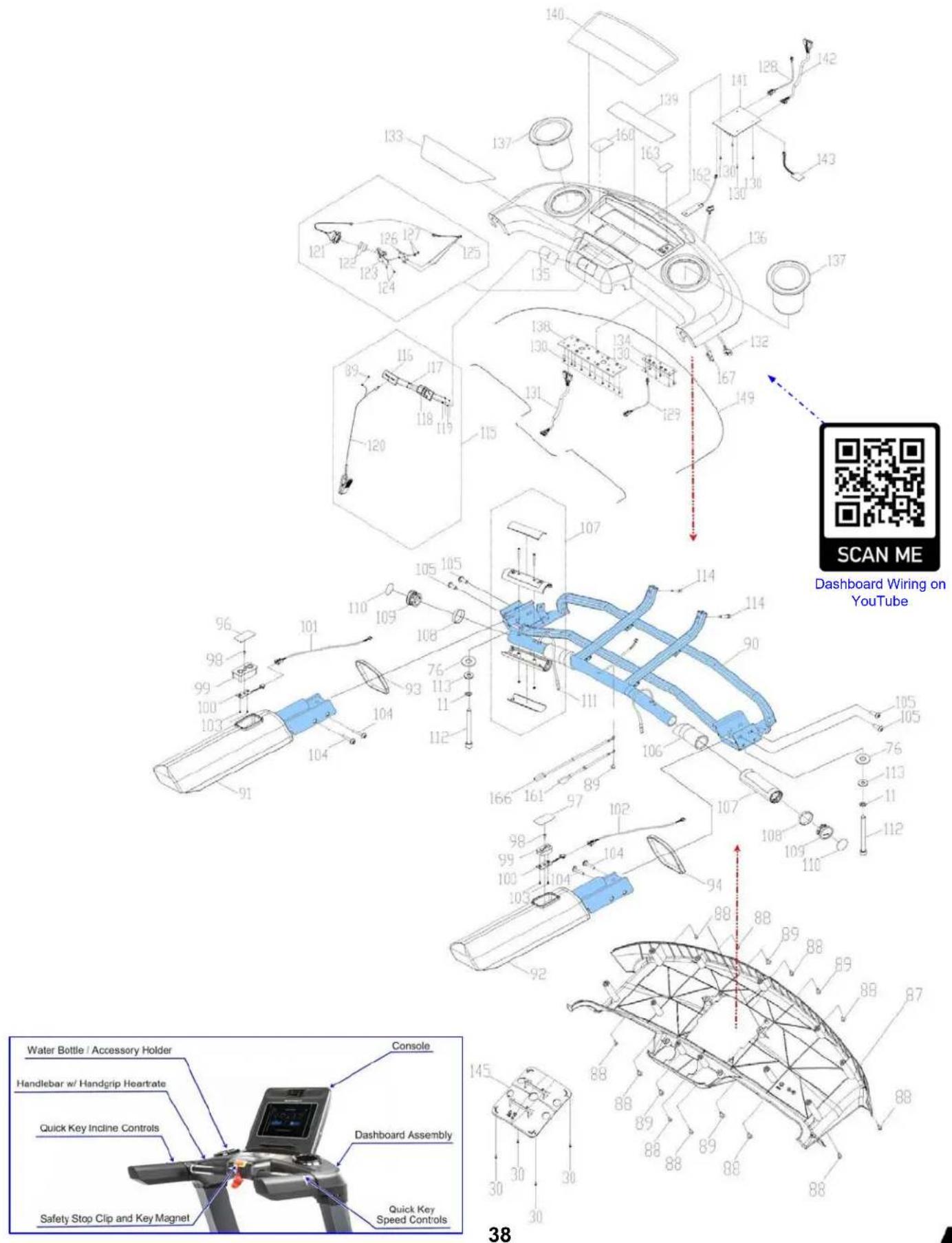
Product Parts Exploded View - Upright Posts Assembly - T800 (T801 & T802)

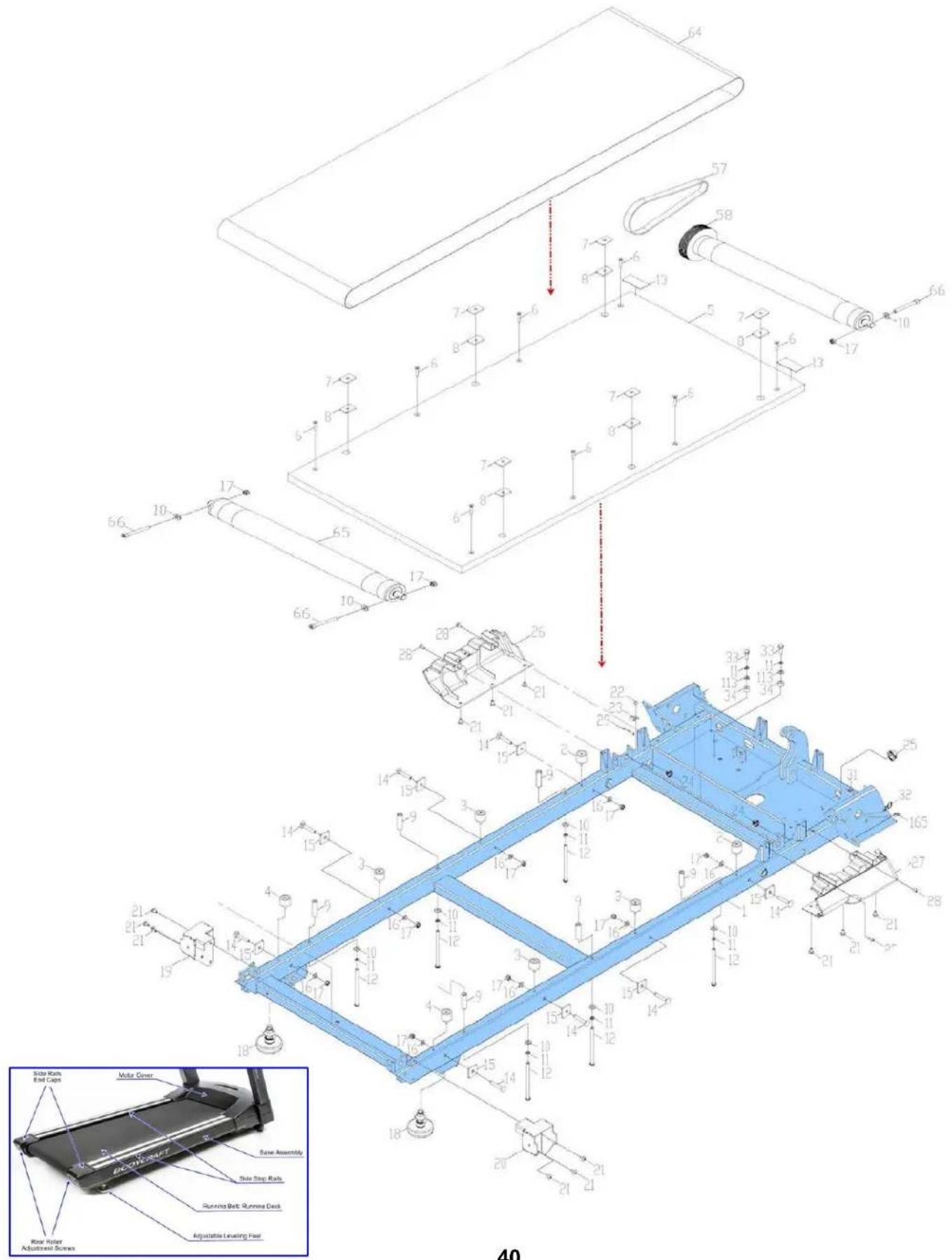
Product Parts Exploded View - Base Covers & Incline Frame - T800 (T801 & T802)

Required Information BEFORE Initiating a Service Case
The following information is needed to help expedite troubleshooting and to ensure the correct part(s) are sent if needed for a repair:
1) What product / model # do you have?
2) Unit serial number?
3) Installed by a dealer or direct sale?
4) Date of installation?
5) Date of service issue?
7) Has the software been updated?
8) What part(s) are being requested?
6) Complaint or problem, including any Error Codes?
9) Any picture or video will help with troubleshooting or exact part(s) needed.
Product Warranty, EXP SERIES - Treadmills T800 (T802) & T400 (T402)
VALID FOR USA AND CANADA ONLY
(Please consult with your local distributor for warranty info specific to your region).
BODYCRAFT warrants its products to be free of defects in materials and workmanship for the time stated below to the original purchaser.
Register your product within 30 days of purchase at www.bodycraft.com or call 800-990-5556
This warranty is valid only in accordance with the following conditions:
The warranty begins on the original purchase date at retail and ends when the original owner disposes of it, either through sale, gift, or otherwise. This warranty is not transferable and is only valid to the original purchaser.
This warranty is available only for purchases made within and the original purchaser currently residing in the USA and Canada. Please consult with your local distributor for warranty information specific to your region. The product must have been registered within 30 days of the original purchase date or supply proof of purchase to validate warranty (original sales invoice).
This warranty does not extend to any losses or damages due to accident, misuse, abuse, neglect, negligence, unauthorized modification or alteration, use beyond rated capacity, unsuitable power sources or environmental conditions, water, tampering, cosmetic damages, or improper installation, handling, repair, maintenance, or application, or lack of proper maintenance.
If the item exhibits such a defect, BODYCRAFT will, at its option, repair or replace it without cost for parts. Shipping and handling charges may apply. (BODYCRAFT may require return of the part(s) or photographic evidence of the damaged part(s) prior to replacement.) Serial number is required.
Parts repaired or replaced will be warranted for the remainder of the original warranty period only.
Residential Warranty :
Frame: Lifetime, Parts: 10 years, Console: 3 years, Labor: 2 years
Headphone Jack, HDMI, CSAFE, ETHERNET & USB Port: 90 days and Labor: None
Commercial Warranty:
Frame: 10 years, Parts: 5 years, Console: 3 years, and Labor: 2 year.
Headphone Jack, HDMI, CSAFE, ETHERNET & USB Port: 90 days and Labor: None
Prisons & Correctional Facilities Warranty:
* No Warranty for all Commercial DC Drive Treadmills installed in any prisons & correctional facilities.
This warranty excludes the following:
- The warranty does not cover normal maintenance or labor charges unless labor terms are listed above.
- Normal cosmetic wear on parts such as paint, seat coverings, foot rails, labels and logos.
- Consumables such as batteries and heart rate belts that do not have a replaceable battery.
- Eprom/Software version upgrades unless determined as necessary.
- Any accessories not included in the original packaging.
* This warranty is in lieu of all warranties, expressed or implied, and/or all other obligations or liabilities on our part, and we neither assume nor authorize any person to assume for us any other obligation or liability in connection with the sale of your BODYCRAFT product. Under no circumstances shall we be liable by virtue of this warranty or otherwise for damage to any person or property whatsoever for any special, indirect, incidental, secondary or consequential damage of any nature whatsoever arising out of the use or inability to use the BODYCRAFT product.
Register your product's warranty at www.bodycraft.com/product-registration.html
Warranty Registration - Cardio
Thank you for purchasing a BODYCRAFT product. To validate the product warranty the fast and easy way, please go on-line now to https://www.bodycraft.com/product-registration.html and register your product. The information you provide will never be distributed to any other individuals or agencies for any purpose. If you prefer to mail your warranty card, have the owner of the product complete the information below and return it to BODYCRAFT within 30 days from the date of equipment installation.
Please Note: Failure to register this product will result in no servicing or authorization of parts to be shipped.
To mail your warranty information, please fill in the information below and mail to: Service Dept., BODYCRAFT, 7699 Green Meadows Dr. Lewis Center, Ohio 43035 (or save postage and register online at https://www.bodycraft.com/product-registration.html)
Warranty Registration
PLEASE PROVIDE BOTH SERIAL NUMBERS BELOW. REQUIRED FOR WARRANTY REGISTRATION:
BASE UNIT SERIAL NUMBER:
CONSOLE SERIAL NUMBER:
Model Type: ____
Date of Purchase
Your Company Name ____
Contact First Name
Contact Last Name
Address
City____State____ZIP____
Email Address____Website____
Phone____Fax____
- Where did you first learn about BODYCRAFT?
a. Dealer b. Website c. Advertisement d. Referral e. Current Customer f. Other
- Why did you purchase a BODYCRAFT product?
a. Design/Appearance b. Dealer Suggestion c. Price/Value d. Quality Construction e. Performance f. BODYCRAFT Reputation g. Other:
- Please indicate your type of facility:
a. Apartment/Condo b. Corporate Fitness Center c. Municipality d. Health Club/Gym/Spa e. Hotel/Resort f. Military Base g. Student Rec Center h. Home
- What other types of equipment does your company or home currently own?
a. Treadmill Brand
b. Elliptical Brand
c. Bike/Indoor Cycle Brand
d. Free Weights/Gym Brand
-
How many people use your facility on a daily basis? _ a. <25 _ b. 25-75 _ c. 76-150 _ d. 150+
-
Do you plan to purchase more fitness equipment in the next 6-12 months?
Yes No
- If you answered "yes" to question 6, what type do you plan to purchase?
a. Treadmill b. Elliptical c. Bike/Indoor Cycle d. Free Weights e. Gym f. Other
- Would you recommend BODYCRAFT to other club or home owners?
____Yes____No
- You are a valued BODYCRAFT customer and your suggestions allow us to continually improve your experience. Is there anything else you would like us to know? Please explain:

natural_image
Simple black-and-white icon of a telephone handset inside a circle (no text or symbols)800.990.5556
SERVICE@BODYCRAFT.COM
WWW.BODYCRAFT.COM
BODYCRAFT
7699 GREEN MEADOWS DR.
LEWIS CENTER, OHIO 43035

- Owner's Manual
- Congratulations and Welcome to the BODYCRAFT Family
- Spending 15 to 30 minutes a day, three times a week, is all you need to start seeing the benefits of a regular exercise program.
- Table of Contents
- Product Safety Information
- Power & Grounding Requirements
- Product Overview
- How Assemble the Treadmill
- How to Setup the Treadmill
- Operation Instructions
- Maintenance & Repairs
- Warranty & Contact Information
- FCC Information
- Safety and Warning for a Treadmill - Grounding Instructions
- Safety and Warning for a Treadmill - Power Requirements T800 (T801 & T802)
- Product Specifications - T800 (T802)
- Small Box 2 of 2
- STEP 1 - Upright Post-Right Wiring Connection
- Only loosely tighten ALL BOLTS until STEP 8
- STEP 2 - Install Upright Post - Right
- STEP 3 - Install Upright Post - Left
- STEP 4 – Prepare for the Dashboard Assembly
- STEP 5 – Installing the Dashboard Assembly
- STEP 7 – Preparing to Fully Tighten the Upright Posts
- Product Assembly
- STEP 8 - "Torque Time"
- STEP 9 - Installing the Handlebar Covers - Right & Left
- STEP 11 – Installing the Upright Post Covers - Right & Left
- STEP 15 - Console Wiring to the Dashboard Assembly.
- STEP 16 - Secure the Console to the Dashboard Assembly.
- STEP 17 - Power Cord
- Product Setup - Wall Outlet, Breaker and Extension Cords
- Product Setup - Spacing Requirements
- Product Setup - Leveling the Treadmill
- Product Setup - Leveling, Running Belt Tension & Alignment
- Follow these steps after the assembly STEPS to ensure proper function of your treadmill!
- T800 SERIES
- Installation Checklist
- BODYCRAFT
- Console Options
- Console Operations Instructions - T800 (T801 & T802)
- Always turn off the treadmill after hours or when not in use.
- Safety Key Clip & Tether
- The following is RECOMMENDED for cleaning supplies:
- Preventive Maintenance - T800 (T801- T802)
- Preventive Maintenance is the responsibility of the owner and not covered under warranty.
- (Example of changing oil and rotating tires on new car.)
- Daily Maintenance Items
- Weekly Maintenance Items
- Monthly Maintenance Items
- Quarterly / Semi-Annual Maintenance Items
- Annual Maintenance Items
- Troubleshooting & Error Codes on DC Motor Treadmill - Basics 1 of 2
- Required Information BEFORE Initiating a Service Case
- Product Warranty, EXP SERIES - Treadmills T800 (T802) & T400 (T402)
- VALID FOR USA AND CANADA ONLY
- This warranty is valid only in accordance with the following conditions:
- Residential Warranty :
- Commercial Warranty:
- Prisons & Correctional Facilities Warranty:
- This warranty excludes the following:
- Warranty Registration - Cardio
- Warranty Registration
Brand : BodyCraft
Model : T800
Category : Treadmills