
VR500 - Rowing Machine BodyCraft - Free user manual and instructions
Find the device manual for free VR500 BodyCraft in PDF.


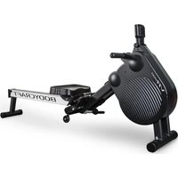
| Product Type | Rowing Machine |
| Brand | BodyCraft |
| Model | VR500 Pro Rower (VR500-RW55) |
| Weight | 46 kg (101 lbs) |
| Maximum User Weight | 350 lbs (150 kg) |
| Resistance System | Full auto-controlled air magnetic resistance |
| Resistance Levels | 32 levels |
| Programs | Manual, 12 Profiles, Race (5 presets + user), Interval (Time/Distance), Custom, HRC (4), Watts |
| Foldable | Yes, with safety pin |
| Transport Wheels | Yes, smooth roll transport wheels |
| Power Supply | AC adapter 6V DC, 1A (1000mA) |
| Display | LCD with time, distance, watts, pulse, SPM, strokes, calories, level, dot matrix profile |
| Heart Rate Compatible | Optional telemetry chest strap (5 kHz) |
| Computer | Advanced computer with quick start, pause, summary |
| Frame Material | Aluminum beam and steel main frame |
| Warranty (Residential) | Frame: Lifetime, Parts: 7 years, Labor: 2 years |
| Warranty (Light Commercial) | Frame: 10 years, Parts: 3 years, Labor: 1 year |
| Assembly Required | Yes, with included tools |
| Adjustable Footrest | Yes, heel rest with 6 positions and adjustable foot straps |
| Handlebar Remote | Yes, wireless remote for program control and resistance |
| Safety Features | Fold safety pin, precautionary safety check, child-proof lock |
Frequently Asked Questions - VR500 BodyCraft
User questions about VR500 BodyCraft
0 question about this device. Answer the ones you know or ask your own.
Ask a new question about this device
Download the instructions for your Rowing Machine in PDF format for free! Find your manual VR500 - BodyCraft and take your electronic device back in hand. On this page are published all the documents necessary for the use of your device. VR500 by BodyCraft.
USER MANUAL VR500 BodyCraft
natural_image
Abstract black geometric sculpture with a white banner (no text or symbols visible)OWNERS • MANUAL
201812

WWW.BODYCRAFT.COM

800-990-5556

SERVICE@BODYCRAFT.COM
VR500-RW55
INTRODUCTION
Congratulations!
Thank you for selecting the VR500 Pro Rower.
The VR500 Pro Rower is one of the finest and most comprehensive rowing machines available.
By choosing the VR500 Pro Rower you have made a decision that will improve the health, fitness and well being for you and your family. The VR500 Pro Rower will provide an efficient, low impact cardiovascular workout that will help improve your energy levels and your quality of life.
Cardiovascular training is vital for all ages and the VR500 Pro Rower will provide an effective workout, producing results that will encourage you to reach your fitness goals and maintain the body you have always wanted.
Spending 15 to 30 minutes a day, three times a week is all you need to start seeing the benefits of a regular exercise program.
We, at want you to enjoy the full benefits of your exercise program, so please take the time to read this manual thoroughly. By doing so you will:
- Save valuable exercise time in the long run.
• Exercise safely and more effectively. - Learn proper techniques.
- Be able to better define your fitness goals.
TABLE OF CONTENTS
INTRODUCTION page 2
TABLE OF CONTENTS page 2
IMPORTANT INFORMATION page 3
Medical / Safety page 3
Care and Maintenance page 3
General Information page 3
GENERAL PARTS IDENTIFICATION page 4
• USING/OPERATING YOUR Bodycraft VR500 Pro
Rower ...... page 5\~8
- Unfolding ...... page 5
- Getting on Safely ...... page 5
- Heel Rest Adjustment ...... page 6
- Foot Strap Adjustment ...... page 6
• Computer Angle Adjustment page 6
- Handle Bar Holder ...... page 7
- Handle Bar Remote ...... page 7
- Foot Strap Release ...... page 7
- Folding page 8
- Transportation and Storage ...... page 8
CORRECT ROWING GUIDE page 9\~10
ASSEMBLY INSTRUCTIONS page 11\~13
DETAILED PARTS LIST page 14
EXPLODED DRAWING page 15
STRETCHING page 16
COMPUTER MANUAL page 17\~31
WARRANTY back cover
IMPORTANT INFORMATION - PLEASE READ
Failure to read and follow the safety instructions below may result in injury.
Medical / Safety
Read this Owner's Manual safety instructions thoroughly to familiarize yourself with the VR500 Rower before using Pro it.
Before beginning any exercise program, consult your physician. He or she can help evaluate your present fitness level and determine the exercise program that is the most appropriate for your age and physical condition.
If you experience any pain or tightness in your chest, irregular heartbeat, shortness of breath, faintness, or unusual discomfort upon exercising, stop and consult a physician.
Adult supervision is required at all times when children are on or near the VR500 Rower. Unsupervised children Pro should keep away from the equipment at all times.
Keep fingers and limbs, loose clothing and hair away from moving parts.
Before each workout on your VR500 Rower we advise Pro that a Precautionary Safety Check is wise. All equipment should be Safety Checked for wear and damage. If you find any damage or defective components STOP using the VR500 Pro Rower IMMEDIATELY. Replace defective components immediately and/or keep the equipment out of use until repaired. For repair help - see General Information on this page.
Care should be taken when getting ON or OFF your VR500 Pro Rower. Please follow the instructions on page 4.
Wear comfortable, lightweight, well-ventilated clothing to help sweat evaporate. Make sure your shoes fit you properly and provide external and lateral stability support to prevent ankle and knee injuries. Wear cross-training, walking or running shoes.
It's very important not to become dehydrated. Your body needs water lost during exercise.
Don't forget to warm-up and cool-down. Limbering up "cold" muscles and cooling down after exercise are important injury-prevention measures.
Use only the accessory attachments recommended by the manufacturer. DO NOT attempt to modify or alter your VR500 Pro Rower as injury may result.
Care and Maintenance
Your VR500 Pro Rower is made of the highest quality materials. It is still important that you take care of your VR500 Pro Rower on a regular basis.
Your VR500 Pro Rower is for indoor use only and should NOT be used or stored in damp areas. Wipe all perspiration from your VR500 Pro Rower after each use.
For safety, inspect your VR500 Pro Rower on a regular basis. When used in a light commercial environment safety check and clean every day. When used in a domestic environment safety check and clean before use.
Components most Susceptible to Wear SEAT ROLLERS - ALUMINUM BEAM [part#001,118]
These parts are easily damaged by dust and dirt and should be cleaned regularly. The SEAT ROLLERS [118] are hidden so all you can do is clean the ALUMINUM BEAM [001]. Using a damp cloth wipe the top of the ALUMINUM BEAM [001]. Pay special attention to the outside edges. Check and remove any black spots.
DRIVE STRAP [part#709]
The DRIVE STRAP [709] is made of high quality nylon webbing which is extremely strong making it almost impossible to break. Even so it is important to check the DRIVE STRAP [709] for wear. Check for nicks or cuts and fraying that may weaken the integrity. Also check that the stitching at the handle bar end is intact. If any of these symptoms are found discontinue use immediately and contact your dealer for a replacement DRIVE STRAP [709].
FOOT REST Assembly
[part#016,027,143,147,314A,367,386A,710]
The FOOT REST Assembly has alot of moving parts. It is essential that these parts be in good condition at all times. Check that the FOOT STRAP BUCKLE firmly holds the FOOT STRAP. Check that the HEEL REST[143] HEEL REST HOLDER[147] self locking system is working correctly. Make sure that all Bolts are tight and firm. If any defects are found discontinue use immediately and contact your dealer for replacement parts.
All FASTENERS [Nuts, Bolts, and Screws]
Regularly inspect all Nuts, Bolts and Screws to insure they are tight and firm.
General Information
The VR500 Pro Rower is designed for Residential and Light commercial use ONLY and should not be used in a full commercial, therapeutic or medical environment.
The official maximum load is 350 lbs or 150kg.
The VR500 Pro Rower has been tested and certified according to EN 957-1 and EN 957-7, Class S.A.
In the unlikely event that your VR500 Pro Rower needs servicing, repairs or something is missing or broken then contact your dealer as soon as possible. They should be able to help you immediately with any and all problems you have. You can also contact us directly at 800-990-5556 or email us at service@bodycraft.com.
It is important to keep your purchase receipt!
You may be asked to produce it too authenticate your Warranty.
DO NOT attempt to modify or alter your VR500 Pro Rower as it will be considered tampering and will invalidate your warranty.
Please continue to read the Owner's Manual and all safety instructions thoroughly to familiarize yourself with the VR500 Pro Rower before using it.
DESIGNERS NOTE: The return spring on the VR500 Pro Rower has been designed with the lightest possible force. There is more than sufficient spring tension to recoil the DRIVE STRAP ASSEMBLY [709] regardless of the return speed of the handle to the start position.
This gives the user an improved level of exercise by increasing the benefit to the hamstring group of muscles at the rear of the thigh. This muscle group is called upon when the user moves the seat forward.
We have faithfully duplicated the "normal" rowing action one would get when rowing on water where the oar is not pulled forward.
FOR SERVICE: Please contact your local dealer or directly at 800-990-5556. You may also send an email to service@bodycraft.com.
VR500-RW55 Pro Rower GENERAL PARTS IDENTIFICATION
The VR500 Pro Rower represents over a decade of research and development and incorporates all the latest technology and long standing consumer requests.
• FULL AUTO CONTROLLED AIR MAGNETIC RESISTANCE SYSTEM
• ERGONOMICALLY CORRECT HANDLEBAR
• FULLY ADJUSTABLE FOOTREST
- SEAT TRAVEL FOR USERS UP TO ABOUT 6'6" (42" Inseam)
• STRONG, STABLE ENGINEERED FRAME
• BUILT-IN CHEST BAND RECEIVER
• BUILT TO EN-957 STANDARDS
• ADVANCED COMPUTER PROGRAMS
• ELEVATED FOR EASE OF ENTRY AND EXIT
• ADJUSTABLE COMPUTER ANGLE AND HEIGHT
• TRANSPORTATION WHEELS
• FOLDS FOR STORAGE

USING/OPERATING YOUR Bodycraft VR500 Pro Rower
Unfolding
Make enough space for the VR500 Pro Rower by clearing a workout area 3.3 x 8.5 feet before setting up your VR500 Pro Rower taking care to ensure the floor is solid and level.
NOTE: While inserted, the FOLD SAFETY PIN prevents the unit from being folded or unfolded. The #028 Fold Foot Lever will still move down when pressed, but the unit will not unlock to allow the unit to be folded or unfolded until you have removed the SAFETY PIN.

![hold down until the ALUMINUM BEAM [001] is vertical 028 ②](/content/2026/05/957668/images/1103d26095db2bd4889d70bf1bf97640e8f776c02b9d65858347491ff489393a.jpg)
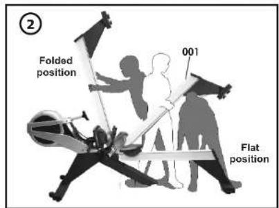

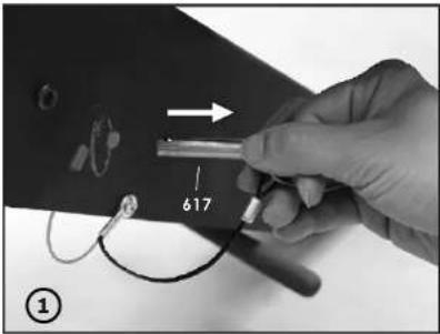
1) With the VR500 Pro Rower in the folded position, remove the FOLD SAFETYPIN [617].
2) With a firm grasp of the ALUMINUM BEAM [001] depress the FOLD - FOOT LEVER [028] down releasing the safety lock allowing the ALUMINUM BEAM [001] to be laid down flat.
3) With the VR500 Pro Rower in the flat position, reinsert the FOLD SAFETY PIN [617] to ensure young children CANNOT fold the rower.
WARNING: When unfolding and folding the VR500 Pro Rower, keep finger and hands away from folding hinge points to avoid serious injury.
Getting on Safely
Getting on safely is a simple procedure. Just be careful that the SEAT [119] is directly underneath you before sitting down.

natural_image
Person performing a row exercise using an equester machine (no text or symbols visible)
natural_image
Side profile of a person performing a rowing exercise on a bench, with a circular machine in the background (no text or symbols visible)1) Straddle the ALUMINUM BEAM [001].
2) Correctly position the SEAT [119] beneath you.
3) Sit down taking care that the SEAT [119] has not moved.
USING/OPERATING YOUR Bodycraft VR500 Pro Rower
Heel Rest Adjustment
There are six heel rest settings numbered 1\~5 and the 6th setting is the maximum setting that is not marked but there is a "STOP" to ensure you do not pull the Heel Rest completely out by mistake. We suggest that you memorize the correct Heel Rest Setting and adjust the Heel Rest before you place your feet.
natural_image
Person adjusting a mechanical component with a white strip, labeled '1st METHOD' and number '143' (no readable text or symbols on the main subject)
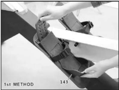
1) Lift the top of the HEEL REST [143] to release the locking mechanism.
2) Push the bottom of the HEEL REST [143] and slide to your desired position.
3) Release the HEEL REST [143] making sure that the two HEEL REST HOLES line up with the two pins securely locking the HEEL REST [143] in place.
Foot Strap Adjustment
A very common mistake is to place the FOOT STRAP [710] too high across your foot. This can cause pain and injury over the long-term and will loosen the FOOT STRAP [710] during exercise. It is important that the FOOT STRAP [710] crosses over the 'ball of your foot' just below your toes.

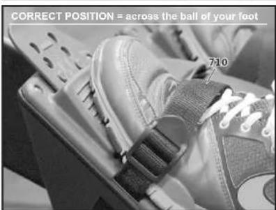
1) Slide your foot under the FOOT STRAP [710] then down fully into the HEEL REST [143].
2) Check to make sure the FOOT STRAP [710] is in the correct position across the ball of your foot.
3) Firmly pull the end of the FOOT STRAP [710] to ensure a light fit.
Computer Angle Adjustment
The COMPUTER [714] and COMPUTER ARM [015] are designed to rotate and pivot giving you adjustment to height and angle.
NOTE: For safety reasons, whilst exercising avoid the DRIVE STRAP [709] touching the COMPUTER [015].


1) Hold the COMPUTER [015] with both hands and rotate and pivot the COMPUTER [714] to the desired height and angle. NOTE: For safety reasons, whilst exercising avoid the DRIVE STRAP [709] touching the COMPUTER [015].
USING/OPERATING YOUR Bodycraft VR500 Pro Rower
Handlebar Holder
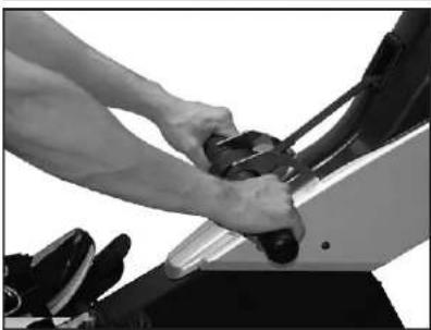
When you have finished your workout remember to store the HANDLE BAR into the HANDLE BAR HOLDER [030].

natural_image
Close-up of a person using a mechanical device on an exercise machine (no visible text or symbols)1) When you have finished your workout place the HANDLEBAR into the HANDLE BAR HOLDER [108] as shown in the diagrams above.
WARNING! Never let go of the Handlebar until it is resting in the HANDLEBAR HOLDER. Releasing it while it is retracted can damage the HANDLEBAR, HANDLEBAR REMOTE, and/or the HANDLEBAR HOLDER. Always carefully place it back into the HANDLEBAR HOLDER. Damage to these components as a result of improper use is considered abuse and will not be covered under warranty.
Handlebar Remote
The HANDLEBAR REMOTE is shipped with the plastic tab preventing the battery from supplying power to the remote to ensure good battery life out of the box. To engage the battery simply remote the PLASTIC TAB and discard.


1) Remove the PLASTIC TAB to engage the battery by pulling in the direction of the printed arrow.
2) You can use the remote to set up your program and to control resistance during exercise, please refer to the computer portion of the manual.
Foot Strap Release
The BodyCraft VR500 Pro Rower is equipped with a quick release FOOT STRAP BUCKLE.

natural_image
Close-up of a hand using a footstrap buckle to repair a dark fabric item (no text or symbols visible)
1) Using your thumb simply lift the tab of the FOOT STRAP BUCKLE up and away and the FOOT STRAP will easily slide through the FOOT STRAP BUCKLE.
USING/OPERATING YOUR Bodycraft VR500 Pro Rower
Folding
Make enough space for the VR500 Pro Rower by clearing a workout area 3.3 x 8.5 feet before setting up your VR500 Pro Rower taking care to ensure the floor is solid and level.
NOTE: While inserted, the FOLD SAFETY PIN prevents the unit from being folded or unfolded. The #028 Fold Foot Lever will still move down when pressed, but the unit will not unlock to allow the unit to be folded or unfolded until you have removed the SAFETY PIN.
![hold down until the ALUMINUM BEAM [001] is 30° degrees 028](/content/2026/05/957668/images/4cc74ac628f99b9990b7c03b4b072f050e87ab1df861f68d89e9a28e1a12623c.jpg)


1) With the VR500 Pro Rower in the flat position, remove the FOLD SAFETY PIN [617].
2) With a firm grasp of the ALUMINUM BEAM [001] depress the FOLD - FOOT LEVER [028] down releasing the safety lock allowing the ALUMINUM BEAM [001] to be lifted up.
3) With the VR500 Pro Rower in the folded position, reinsert the FOLD SAFETY PIN [617] to ensure young children CANNOT unfold the rower.
WARNING: When unfolding and folding the VR500 Pro Rower, keep finger and hands away from folding hinge points to avoid serious injury.
Transportation and Storage
The VR500 Pro Rower is fitted with TRANSPORTATION WHEELS making it fairly simple for one person to move it by themselves. The VR500 Pro Rower is a large rowing machine that weights 46kg (101lbs) so you may require help when moving it around depending on your size and strength.
natural_image
Black-and-white photo of a person performing a high kick with a basketball on their back (no text or symbols visible)
natural_image
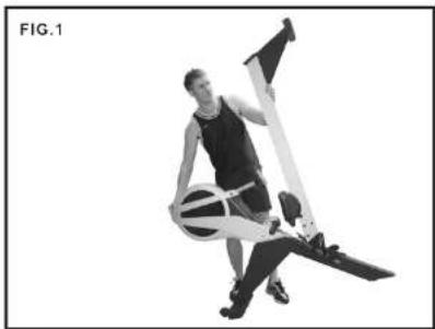
Man holding a white object next to a smooth bell transporter device, with an inset close-up of the device (no text or symbols visible)1) Position yourself as shown in "Fig. 1". Hold onto the rowing machine with both hands. Using your body weight, slowly tip the rowing machine towards the front while at the same time move around to the front of the machine to support the weight.
2) Once balanced (see Fig 2) wheeling the machine is made easy with the "Smooth Roll Transport Wheels".
3) When resting the rowing machine to the floor follow the reverse of step one (as shown in Fig. 1).
CORRECT ROWING GUIDE
Over Reaching
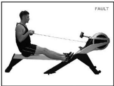
FAULT
The body stretches too far forward. The shins may be past vertical. The head and shoulders tend to drop towards the feet. The body is in a weak position for the stroke.

natural_image
Person performing a rowing exercise on an equestrian (no text or symbols visible)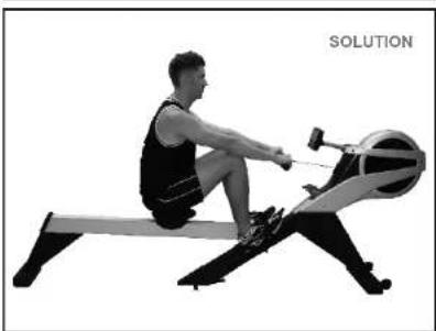
natural_image
Person performing a rowing exercise on an equestrian machine (no text or symbols visible)SOLUTION
The shins are vertical. The body is pressed up to the legs. The arms are fully extended and relaxed, body tilted slightly forward. This position should feel comfortable.
Rowing with Arms Bent
FAULT
The user starts the stroke by pulling with the arms rather than pushing with the legs.

natural_image
Person using a rowing machine in a stationary exercise (no text or symbols visible)
natural_image
Person performing a rowing machine on a circular apparatus (no text or symbols visible)SOLUTION
The user starts the stroke by pushing the legs and bracing the back with the arms fully extended and relaxed.
Bent Wrists
FAULT
The user bends their wrists at any time through the stroke.
natural_image
Person performing a rowing exercise on a stationary bike (no text or symbols visible)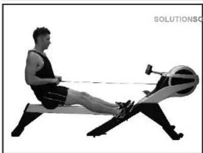
natural_image
Person performing a rowing exercise on a stationary bike (no text or symbols visible)SOLUTION
Always row with flat wrists through the entire stroke.
CORRECT ROWING GUIDE
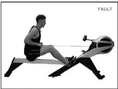
Pulling the Body to the Handle
FAULT
At the finish, the user, instead of pulling the handle to the body, pulls themselves forward to the handle.
natural_image
Person performing a rowing exercise on an equestrian (no text or symbols visible)
natural_image
Person performing a rowing exercise on a stationary bike (no text or symbols visible)SOLUTION
At the finish the user leans back slightly, holds the legs down and draws the handle to the body using the upper body as a firm platform.
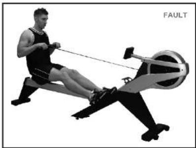
Flying Elbows
FAULT
The user's elbows are sticking out from the body at the finish and the handle is at chest level.
natural_image
Person performing a rowing machine on a circular apparatus (no text or symbols visible)
natural_image
Person performing a rowing machine with a resistance bar, labeled 'SOLUTION' in the corner (no other text or symbols)SOLUTION
Draw the handle to the body. The wrists are flat and the elbows pass close to the body. Elbows extend behind the body as the handle is drawn to the waist.
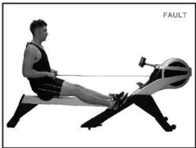
Locking the Knees
FAULT
At the end of the stroke the user locks the knees making the legs straight.
natural_image
Person performing a rowing exercise on a stationary bike (no text or symbols visible)
natural_image
Person performing a rowing exercise on a stationary bike (no text or symbols visible)SOLUTION
Always keep the legs slightly bend in the fully extended position..do not lock the knees.
VR500 ROWER ASSEMBLY INSTRUCTIONS
Introduction
Congratulations on your purchase of the VR500 Rower. This product has been designed and manufactured to meet the needs and requirements of domestic use.
Please carefully read the instructions prior to assembly and first use. Be sure to keep the instructions for reference and/or maintenance.
If you have any further questions, please contact us. We wish you lots of success and fun while training.
Where to find the serial number
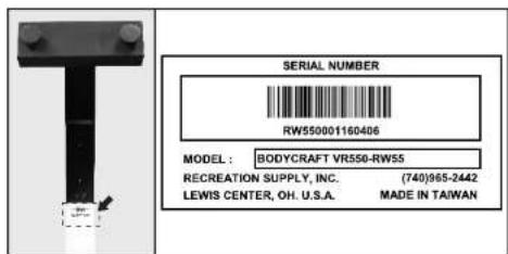
Check List IF ANY OF THESE PARTS ARE MISSING CONTACT YOUR DEALER IMMEDIATELY.

VR500 ROWER ASSEMBLY INSTRUCTIONS
STEP1
We recommend that you clear a 6.5' x 8.5" (2 x 2.5 Meter) area for working space before unpacking the Vr500 Rower.
STEP 2
Open the carton as shown in the diagram below. NOTE: To protect the VR500 Rower while assembling we suggest that you do not remove the Protective Packing Material until it is absolutely necessary.

natural_image
Isometric line drawing of two stacked rectangular compartments with internal structural components (no text or symbols)STEP 3
Assemble the STABILIZER FRONT [005] and SUPPORTER FRONT [020) with 2 x BOLTS (356A) and lighten firmly.
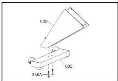
STEP 4
a) Place the MAIN FRAME [002] IN THE Carton Lid and poly foam as shown in the diagram below.
b) If pre-installed, remove the 4 bolts from the main frame with the provided tools ("Bolts may be located in a hardware bag).
c) Connect AC ADAPTOR CABLE [712] to AC CABLE [720]
d) Install the FRONT STABILIZER/SUPPORTER FRONT from STEP 3 using 4 × BOLTS [367] making sure to start all four bolts before tightening. WARNING! Be careful not to pinch [712] AC ADAPTER CABLE and [720] AC CABLE. Tighten Firmly.

STEP 5
a) Remove the ALUMINUM BEAM [001] from the carton and place it on top of the carton lid as shown in the diagram below.
b) Assemble REAR STABILIZER [006] with 2 x BOLT[367] + 2 NUT [213] and tighten firmly.
c) Assemble ALUMINUM BEAM END CAP [116] with 2 x BOLT [303A] and tighten firmly.
d) Remove the cable tie from the SEAT CARRIAGE [009].
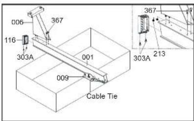
STEP 6
a) Remove the partky assembled rower from the carton lid and place it in the upright position as shown below. b) Remove the SAFETY PIN[617]. c) Step on the FOLD-FOOT LEVER[028] and lift PIVOT BRACKET [003] until you hear and feel it "LOCK" as shown below. d) Insert the FOLD SAFETY PIN [617]

STEP 7
a) Remove the SAFETY STRAP HOLDER and discard place the HANDLE BAR in it's HOLDER.
c) Remove 4 x BOLT [367] from PIVOT BRACKET [003] with the TOOL provided.
d) Loosely assemble the ALUMINUM BEAM [001] using 2 x BOLT [367] as shown below. DO NOT TIGHTEN UNTIL INSTRUCTED.

VR500 ROWER ASSEMBLY INSTRUCTIONS
STEP 8
a) If pre-installed*, remove the 4 bolts from the ALUMINUM BEAM [001] with the provided tools ('Bolts may be located in a hardware bag). b) Loosely assemble FOOT PEDAL-FRAME [016] with 4 x BOLT [367].
NOTE: You may have to reposition the ALUMINUM BEAM unfold the track to properly align the holes to get all bolts started (refer to the Using/Operating your Rower section). Once all of the bolts are started TIGHTEN all bolts firmly.

STEP 9
a) Remove 4 x BOLT [319] from SEAT [119] with the TOOL provided. b) Assemble the SEAT [119] with the same 4 x BOLT [319] and tighten firmly.

STEP 10
a) Remove 4 x BOLT [304] from SEAT CARRIAGE [009] with the TOOL provided. b) Assemble 2 x SEAT CARRIAGE COVER [117] with the same 4 x BOLT [304] and tighten firmly.

STEP 11
a) Connect the AC ADAPTOR [715] into the main power socket.

STEP 12
Remove all Protective Packing Material and discard.
ASSEMBLY COMPLETE
It is important to read the Owner's Manual and all safety instructions thoroughly to familiarize yourself with the VR500 Dual Mode Rower before using it.
VR500-RW55 DUAL MODE ROWER PARTS LIST
| PART No. | DESCRIPTION Q'TY | PART No. | DESCRIPTION Q'TY | PART No. | DESCRIPTION Q'TY | |||
| 001 | ALUMINUM BEAM | 1 | 139 | RETURN SPRING ASSEMBLY | 1 | 428 | WASHER-ø 10x16x2T | 2 |
| 002 | MAIN FRAME | 1 | 140 | FLYWHEEL FAN | 1 | 461 | WASHER PLATE | 2 |
| 003 | PIVOT BRACKET | 1 | 141 | SEAT STOPPER | 2 | 508A | SCREW-M4x8 | 12 |
| 005 | STABILIZER - FRONT | 1 | 142 | SPECIAL SEAT ROLLER | 2 | 514 | TAPPING SCREW-3/16"x1/2" | 6 |
| 006 | STABILIZER - REAR | 1 | 143 | HEEL REST | 2 | 515 | TAPPING SCREW-3/16"x5/8" | 4 |
| 007 | REAR BRACKET | 1 | 144 | FOOT LEVELING ADJUSTER | 4 | 538 | TAPPING SCREW-3/16"x1 1/4" | 4 |
| 008 | ALI HANDLE BAR | 1 | 145 | SPRING LOADED FOOT | 1 | 540 | TAPPING SCREW-M4x12mm | 8 |
| 009 | SEAT CARRIAGE | 2 | 147 | HEEL REST HOLDER | 2 | 541 | SCREW-M4x8mm | 4 |
| 010 | SEAT CARRIAGE SHAFT | 2 | 149 | BUSHING | 2 | 611 | RETAINING RING | 1 |
| 011 | ROLLER ADJUSTMENT BOLT | 4 | 151 | SENSOR CABLE ASSEMBLY | 1 | 612 | SPLIT PIN | 2 |
| 012 | ROLLER ADJUSTMENT PLATE | 4 | 152 | MAIN COVER JOINT POST | 1 | 617 | FOLD SAFETY PIN + RING & CABLE | 1 |
| 013 | FOLD-SLIDER | 1 | 155 | TRIM COVER | 1 | 619 | SPRING | 1 |
| 014 | FOLD-LEVER | 1 | 158 | CABLE PLUG | 1 | 620 | SPRING | 1 |
| 015 | COMPUTER ARM | 1 | 159 | BUSHING | 2 | 621 | SPRING | 1 |
| 016 | FOOT PEDAL-FRAME | 1 | 161-IR | POD ASSEMBLY (Bf200) | 1 | 700 | TENSION CABLE | 1 |
| 019 | ROLLER SPACER | 2 | 204 | NUT-M6xP1.0 | 2 | 701 | MOTOR | 1 |
| 020 | SUPPORTER-FRONT | 1 | 205 | NUT-M8xP1.25 | 2 | 703 | COMPUTER CABLE | 1 |
| 021 | SEAT STOPPER-BOLT | 1 | 207 | NUT-3/8"x26x6T | 2 | 704 | COMPUTER CABLE | 1 |
| 022 | BEARING BRACKET-B | 1 | 211 | NUT-M5x0.8 | 2 | 705 | COMPUTER CABLE | 1 |
| 023 | BEARING BRACKET-A | 1 | 212 | NUT-M6x1.0 | 8 | 706 | COMPUTER CABLE | 1 |
| 024 | FOOT PEDAL ASSY BACKING PLATE | 1 | 213 | NUT-M8xP1.25 | 10 | 707 | SENSOR CABLE "Y" connect | 1 |
| 025 | FOLD ROD ASSEMBLY | 1 | 214 | NUT-3/8" | 1 | 709 | DRIVE STRAP | 1 |
| 027 | STRAP HOLDER | 2 | 215 | NUT-3/8"x26x6T | 2 | 710 | FOOT STRAP | 2 |
| 028 | FOLD-FOOT LEVER | 1 | 225 | NUT | 1 | 711 | CHEST BAND RECEIVER | 1 |
| 030 | HANDLE BAR HOLDER | 2 | 303A | BOLT-M5xP0.8x8mm | 2 | 712 | AC ADAPTOR CABLE | 1 |
| 106 | COMPUTER CASE NUT COVER | 2 | 304 | BOLT-M5xP0.8x12mm | 5 | 714-BF | COMPUTER (Bf200) | 1 |
| 107 | COMPUTER ARM SPACER | 2 | 314A | BOLT-M4xP0.7x6mm | 8 | 715-BF | AC ADAPTOR 6V 1A (1000ma) | 1 |
| 110 | COVER-HUB | 2 | 319 | BOLT-M8xP0.7x16mm M8xP1.25x16mm | 4 | 720 | AC ADAPTOR CABLE | 1 |
| 111A | COVER MAIN RIGHT | 1 | 342A | BOLT-M8x30mm | 2 | 802 | BEARING 6000ZZ IJK | 2 |
| 111B | COVER MAIN LEFT | 1 | 349 | BOLT-M8x90L | 1 | 702 | Sensor | 2 |
| 113 | WHEEL | 2 | 356A | BOLT-3/8"X2 1/2" | 2 | |||
| 115 | STANDARD CAP | 4 | 359 | BOLT-M5xP0.8x20mm | 1 | |||
| 116 | ALUMINUM BEAM END CAP | 1 | 360 | BOLT-M6xP0.8x12mm | 6 | |||
| 117 | CARRIAGE COVER | 2 | 360C | BOLT-M6(∅9)xP1.0x10mm | 4 | |||
| 118 | SEAT CARRIAGE ROLLER | 4 | 367 | BOLT-M8xP1.25x16mm | 18 | |||
| 119 | SEAT | 1 | 370 | BOLT-M8xP1.25x40mm | 2 | |||
| 122 | PLUG | 2 | 378A | BOLT-3/8"X4 1/8" | 1 | |||
| 123A | FOAM GRIP | 2 | 384 | U-BOLT | 1 | |||
| 132 | STRAP SLOT TRIM | 1 | 386A | BOLT-M5xP0.8x8mm | 4 | |||
| 134 | POLY "V" DRIVE BELT | 1 | 403 | WASHER-M5x10x1T | 2 | |||
| 136 | CLUTCH ASSEMBLY | 1 | 412 | WASHER-M8x12x1.0T | 6 | |||
| 137 | RETURN SPRING - DRUM | 1 | 414 | WASHER-M8x16x2.0T | 6 | |||
VR500-RW55 PRO ROWER EXPLODED DRAWING

STRETCHING
Stretching should be included in both your warm up and cool down, and should be performed after 3-5 minutes of low intensity aerobic activity or calisthenic type exercise. Stretching Movements should be performed slowly and smoothly, with no bouncing or jerking. Move into the stretch until slight tension, not pain, is felt in the muscle and hold for 20-30 seconds. Breathing should be slow, rhythmical and under control, making sure never to hold your breath.

natural_image
Line drawing of a woman in athletic wear performing a stretching pose (no text or symbols)- Quadriceps Stretch
Reach behind body with one hand, grasp top of foot and pull heel toward buttocks while maintaining an erect and upright posture. Hold for 20-30 seconds and release. Repeat for opposite leg.
natural_image
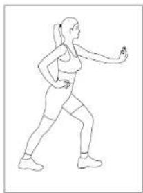
Line drawing of a person in a dynamic pose, possibly performing a martial arts or exercise pose (no text or symbols)- Calf, Achilles Stretch
Keeping back leg straight and foot flat on floor with toes pointed straight ahead, move hips forward by bending knee on front leg. Hold for 20-30 seconds and release. Repeat for opposite leg.

natural_image
Line drawing of a person performing a forward bend stretch (no text or symbols)- Back Stretch
With arms extended and hipsdirectly over feet, lower upper body below hand level by bending at the knees. Hold for 20 - 30 seconds and release.
natural_image
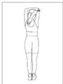
Line drawing of a person viewed from the side, showing a wide stance with no text or symbols- Rear Upper Arm Stretch
Grasp elbow and pull hand toward midline of the body while maintaining an erect and upright posture. Hold for 20 - 30 seconds and release. Repeat for opposite arm.

natural_image
Line drawing of a person performing a leg raise exercise (no text or symbols)- Hamstring, Lower Back Stretch
Holding thigh against upper body, extend leg toward ceiling. Hold for 20-30 seconds. Repeat for opposite leg.
- Buttocks, Hips, Abdominal Stretch
While keeping both shoulders in contact with the ground, gently pull knee toward the ground. Hold for 20-30 seconds and release. Repeat for opposite side.

natural_image
Line drawing of a person lying prone on their back (no text or symbols)
natural_image
Line drawing of a seated woman in profile view, no text or symbols present- Inner Thigh Stretch
With soles of feet together, lean forward from the waist while applying downward pressure to the inside of the knees. Hold for 20 - 30 seconds and release.

natural_image
Line drawing of a person performing a seated exercise with a foot and ankle (no text or symbols)- Chest, Shoulder, Upper Arm Stretch Move buttocks forward away from arms while keeping arms extended back and palms on ground. Hold for 20-30 seconds and release.
DISPLAY DESCRIPTION

TIME / 500M: Displays the calculated current pace per 500 Meters. The display changes with every stroke to provide immediate feedback.
METER: Displays calculated distance traveled in Meters. Or, if a distance goal is selected, the display will count down from preset distance to 0.
WATT: Displays the current user power output in watts.
PULSE: Displays the current user Heart Rate. This feature is only available with the optional Telemetry Heart Rate Chest Strap.
TIME: Displays the elapsed time during workout. Or, if a time goal is selected, the display will count down from present time to 0.
SPM: Displays current strokes per minute. The display changes with every stroke to provide immediate feedback.
STROKES: Displays # of strokes completed. The display changes with every stroke to provide immediate feedback.
CALORIES: Displays approximate calorie expenditure. Or, if user preset a calorie goal, this display will count down from preset calorie goal to 0.
LEVEL: Displays the current resistance level. There are 32 resistance levels; 2 levels per LCD row.
KEY FUNCTIONS


Press this key during workout to end the program and enter Cool down for 5 minutes. The default resistance is at level 1 and can be adjusted up to level 5. Press (STOP) button to end Cool Down and review summary.

Reverse back to main screen during Setup; Pause; Workout Summary and Engineering mode.

Press (BACK) button during program selection or Setup, it will go back to last setting. Press (STOP) button during program execution to end the program and enter summary review. Press and hold (STOP) button for 2 seconds to reset the display and return to main screen.

Confirm setting or selection.

Change selection or value Increase resistance level

Change selection or value Decrease resistance level
POWERING ON YOUR ROWER
Once your rower is fully assembled then you are ready to power on your rower for the first time. Insert the plug-in adapter into the front of rower and plug in the power supply into the wall. On the initial power up, the computer will automatically power up and all the LCD segments will briefly light up for about 2 seconds, then main screen will appear with message scrolling – START ROWING OR SELECT A PROGRAM. If not, check power connections and circuit breakers.
This computer is built with auto power save mode. When there is no activities detected for 4 minutes, the computer display will turn off automatically to save power. To wake up the display, simply press any key or row.
OPERATION
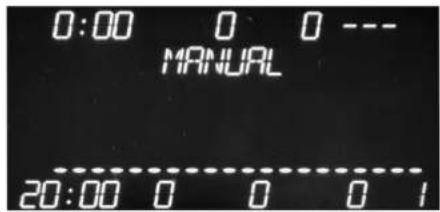
| Quick Start: | The quickest way to start a workout is to simply start rowing. This will initiate the Manual mode. In Quick Start mode, the Time will count up from zero, and display a flat profile. All workout data will start accrue and the workload may be adjusted manually by pressing (UP ▲/DOWN ▼). The dot matrix display will show only the bottom row lit at first. As you increase the workload, more rows will light up indicating a harder workout. There are 32 levels of resistance. Each of the 16 rows represents 2 resistance levels. The handlebar will get harder to pull as the rows increase. The dot matrix has 20 columns of lights and each column represents a distance traveled of 250 Meters (at default). At the end of the 20 column (or 5000 Meters) the display will wrap around and start at the first column. |
| Standard Operation: | Main Screen→Program Selection→User Setting→Goal Selection→Start Program→End Program→Review summary.In the main screen, press (UP ▲/DOWN ▼) button to toggle through a list of programs. When the desired program appears, press (OK) to confirm the program selection.Once a program is selected, the next step is to select a User. (See User Mode section for how to set up a user profile.) If User 0 is selected, all user data (ie. age, weight...) will appear one at a time for adjusting. Press (UP ▲/DOWN ▼) button to adjust the value and (OK) to confirm each setting. If User 1-4 profile is set up and selected, then it will bypass the user data setting and go to Goal options.There are TIME, DISTANCE & CALORIES 3 goal options to choose as the program goal. Once a goal is selected, the program setting is now completed and program will begin.This computer is equipped with the Program Quick Start function. You may row at anytime during program setting to bypass the remaining program settings (use default values) and jump start the program right away. |
OPERATION
| Pause Function: | The computer comes with a Pause function for a quick break after program has started. When User stops rowing, the computer will enter Pause mode with “PAUSED” display and stop data accumulating for a period of 4 minutes. To resume, simply row again. If the computer is paused more than 4 minutes, it will reset and turn off screen to save power. |
| Review Summary: | When the program goal is reached, the program timer will switch to count up instead. When (STOP) button is pressed during the program, the program will end and the workout summary will be displayed for review. If USER1-4 was selected before the workout, the options of saving the workout summary into USER's workout history as well as saving this workout as a custom program will appear during this time. The saving custom program function only works if it is a profile program, Manual or Interval. |
| User Mode: | There are 5 user modes, Users 0-4. User 0 is the guest user which means any data entered or collected will not be saved after workout. Users 1-4 contain memory banks to remembered personal data as well as workout history. To set up User's profile, select “USER DATA” during program selection and press (OK) button to confirm. Inside “USER DATA”, there are 3 options to select from: “USER EDIT” for editing user profile; “USER REVIEW” for workout history review and “USER DELETE” to delete user profile or workout history. |
MANUAL MODE

As the name implies, in Manual mode, you control the workload. You can simply start rowing as a Quick Start, or press (UP ▲/DOWN ▼) in main screen to select "MANUAL" and press (OK) button to confirm. Select a User 1-4 or 0 as the guest user to start. The appropriate settings will be prompted on the display following the User selection for the adjustment. Once setup is completed, the program will begin. You may press (UP ▲/DOWN ▼) button to adjust the resistance level during program.
PROFILE MODE
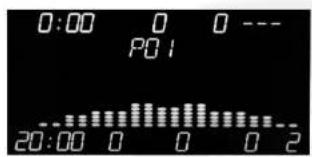
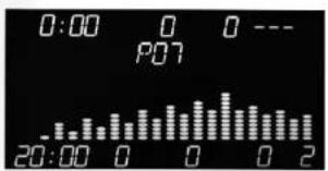
Press (UP ▲/DOWN ▼) in main screen to select "PROFILES" and press (OK) button to confirm. There are P1-P12 profiles to choose from. Pick the desired one and press (OK) to confirm the selection and proceed to user settings. You may press (UP ▲/DOWN ▼) button to adjust the resistance level during program.




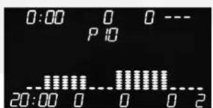

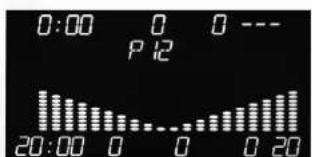
Press (UP ▲/DOWN ▼) in main screen to select "RACE" and press (OK) button to confirm.
There are 5 preset races to race against.
You can also pick USER 1-4 to race against if there is a saved user workout history inside.
If there is no saved data inside a User, the display will prompt with "NO USER DATA" and return back to 1 face selection.
| ○ Individual 500m (Default time goal is 3:00) | |
| ○ Beginner Track 1000m (Default time goal is 6:00) | |
| ○ Olympic Track 2000m (Default time goal is 12:00) | |
| ○ Long Track 5000m (Default time goal is 30:00) | |
| ○ Oxford Boat Race 6779m (Default time goal is 40:00) | |
| ○ USER 1-4 User average time/500m |
The dot matrix will display both User and PC's progress during program. When the target distance is reached, the race will end and winner will be displayed.


INTERVAL MODE
Press (UP ▲/DOWN ▼) in main screen to select "INTERVAL" and press (OK) button to confirm. There are "INTERVAL TIME" (displayed with INT TIME) and "INTERVAL DISTANCE" (displayed with INT DISTANCE) for selection.
If "INTERVAL TIME" is selected, you may adjust the WORK TIME (default of 1:00 minute) as well as REST TIME (default 0:30 seconds to max time allowed 5:00 minutes) to the desired time. You may also change the total number of INTERVALS (default 10 intervals). Afterwards, you may select the WORK LEVEL (default 12) for workout. Once the setting is completed, the program will begin and you can still adjust WORK LEVEL during WORK segments portion of the exercise. The computer will start with WORK segment and switch to REST segment once the WORK time is reached. It will alter between these two segments until the number of INTERVALS is reached.
The difference between INTERVAL TIME and INTERVAL DISTANCE is the WORK segment setting. One is set for Time and the other one is set for Distance. If "INTERVAL DISTANCE" is selected, you may adjust the WORK DISTANCE (default 100m to max 1000m). Everything else works the same way as INTERVAL TIME.

User Data mode is designed to store all your personal information so that you can get into your workout quickly without going through all the settings every time. It also track your workout history if you choose to do so. In main screen, press (UP ▲/DOWN ▼) to select "USER DATA" and press (OK) button to confirm. There are 4 User spaces to store your personal data. You have the options of "USER EDIT" to edit your personal profile; "USER REVIEW" to review your workout history and "USER DELETE" to delete either User Profile or Workout History.
The default User IDs are USER 1-4; however once you input your name into a User #, the User ID will switch to display the initial of your name you entered. Press (UP ▲/DOWN ▼) button to adjust and (OK) to confirm the adjustment. (To end a Name entry, press and hold ENTER button for a few seconds.) For time saving and better workout experience, it is recommended that you set up your user profile before the workout.
CUSTOM PROGRAM MODE
Custom programs are designed for users to store their favorite programs. There are two ways to build a custom program. User could save a workout program at the end of the workout. Or build a profile program one segment at a time using CUSTOM EDIT function.
Inside the CUSTOM PROGRAM mode, user have the options of "CUSTOM WORKOUT" to recall their favorite program and jump to exercise right away; "CUSTOM EDIT" to modify a saved program or build a brand new one and lastly "CUSTOM DELETE" to clear a saved program from the memory.
When you are building or modifying a program profile, each segment will blink and waiting for an input. Press (UP ▲/DOWN ▼) button to adjust and (OK) to confirm the adjustment and go to next segment. To finish the program building without going through all segments, just press and hold (OK) button for a few seconds and the program will be saved.
This program only works when you wear the optional Telemetry Chest Strap which provides steady heart rate signal. The HRC program is designed to keep your heart rate at the constant level you have selected. The computer will check your current heart rate and adjust the resistance when necessary.
There are 4 HRC programs built in: preset 60% MAX HR; 75% MAX HR; 85% MAX HR and set your own TARGET HR. press (UP ▲/DOWN ▼) Then select the desired HRC program to begin. Since the resistance is controlled by the computer, it can't be adjusted by the user manually during program.
NOTE: Your heart rate is an excellent indicator of the amount of stress placed on the cardiovascular system. Your target heart rate, the intensity needed to improve cardiovascular fitness, depends primarily on your age and not your state of fitness. It is calculated as a percentage of your maximum heart rate, estimated as 220 minus your age. In order to get the most accurate reading, it is recommended to enter your age before your workout. To select a target heart rate is optimal for you, refer to the TARGET HEART RATE CHART.
IMPORTANT: Always consult with your physician before beginning any HRC program. While increasing your heart rate is an important part of exercise, it is also critical that your heart rate is not too high. Start from lower target range and slowly increase your target as your fitness level improves.

This computer is equipped with a built-in receiver that uses the international standard 5 kHz bandwidth for your heart rate monitoring. Your heart rate signal will only register on the computer if you are wearing a compatible chest belt. Please follow the instructions with your optional chest belt for proper operation.
(Note: The transmitter may fluctuate erratically if you are too close to other heart rate monitoring equipment or there is other electronics nearby, such as TV, Radio...)

natural_image
Black athletic balance beam with 'RICHINI GOURF' branding (no additional text or symbols)(Chest Belt Sold Separately)
Calculating your Target Heart Rate (T.H.R.)
Your optimal heart rate range during exercise is referred to as your training zone. To achieve the most effective results you should perform your exercise within your training zone. Refer to the TARGET HEART RATE CHART to calculate your T.H.R at 60%,75%,85% of your suggested training zone. We suggest you begin your workout program at the 60% T.H.R level and increase your T.H.R % as your fitness level improves. The Target Heart Rate formula is: 220 - age x T.H.R % (e.g.:220 -30 years old x 60% = T.H.R 114)

line
| AGE | 85% Sprint | 75% Run | 60% Jog | | --- | --- | --- | --- | | 10 | 180 | 160 | 125 | | 15 | 175 | 155 | 120 | | 20 | 170 | 150 | 115 | | 25 | 165 | 145 | 110 | | 30 | 160 | 140 | 105 | | 35 | 155 | 135 | 100 | | 40 | 150 | 130 | 95 | | 45 | 145 | 125 | 90 | | 50 | 140 | 120 | 85 | | 55 | 135 | 115 | 80 | | 60 | 130 | 110 | 75 | | 65 | 125 | 105 | 70 | | 70 | 120 | 100 | 65 | | 75 | 115 | 95 | 60 | | 80 | 110 | 90 | 55 | | 85 | 105 | 85 | 50 | | 90 | 100 | 80 | 45 | | 95 | 95 | 75 | 40 | | 99 | 90 | 70 | 35 |
WATT MODE
This program is controlled by the WATT goal user inputted. The WATT calculation is based on speed and workload. The computer will adjust the workload related to your stroke per minute and maintain your target WATT goal. The faster the speed is, the less workload it will be and vice versa.
In main screen, press (UP ▲/DOWN ▼) to select "WATTS" and press (OK) button to confirm. After user settings, user may adjust the WATT CONTROL value (default 100W with 5W increment) to the desired one. Once the program goal is set, the program will begin. During program, you may change the WATT CONTROL goal by pressing (UP ▲/DOWN ▼) button to the new setting.

WIRELESS HANDLEBAR CONTROLLER PAIRING

natural_image
Black cylindrical device with a triangular button labeled 'OK' and plus, no visible text or symbols beyond the button indicators.The rower computer is paired with handlebar controller in the factory. The only time you need to pair it again is when you have two or more same rowers in the room. If that is the case, you will need to set up each rower controller with a different code in order to avoid controller interference.
To pair the handlebar controller with the computer correctly, please follow the steps below:
Step 1: In the main screen of the computer, press and hold both (UP ▲) & (DOWN ▼) buttons at the same time for a couple of seconds to enter "Engineering mode". The screen will show "ENGINEERING MODE".
Step 2: Press (UP ▲/DOWN ▼) button to get to "IFR CODE" selection and press (OK) to confirm. The screen will display current factory setting of "SET 255 CRV 255" (default code 255). At this time, the computer is ready to change the code.
Step 3: Now switch to use the handlebar controller keys. Press and hold (HOME) key while press (UP ▲) or (DOWN ▼) key at the same time to adjust the code up or down. The both numbers of "SET xxx CRV xxx" will be adjusted at the same time. Release the keys after adjustment. The available codes to use are 0 – 255.
Step 4: Once the desired code appears on the display, press the (OK) button on the computer to confirm the adjustment and the screen will display "IFR CODE SET" to indicate the new code is now activated. Press (HOME) button to go back to main screen and finish the pairing.
IMPORTANT! If you have two or more rowers are located in the room, you will need to adjust the pairing code to prevent controller interference. To change the code, refer to the WIRELESS HANDLEBAR CONTROLLER PAIRING section of the owners manual.
UNITS OF MEASUREMENT SETTING
Step 1: In the main screen, press (UP ▲/DOWN ▼) buttons at the same time for a couple of seconds to enter "Engineering mode". The screen will show "ENGINEERING MODE".
Step 2: Press (UP ▲/DOWN ▼) button to get to "UNITS SETTING" and press (OK) button to confirm. The default setting of "ENGLISH" system will be displayed.
Step 3: Press (UP ▲/DOWN ▼) button to change it to "METRIC" system and (OK) button to confirm the setting and a message of "UNITS CONFIRMED" will appear. Press (HOME) button to go back to main screen and finish the setting.
NOTE: The English/Metric settings are in reference to the users Body Weight only. Rowing distance will always be displayed in Meters.
INFRARED REMOTE CONTROL INSTRUCTIONS—REPLACING THE BATTERY
STEP 1
Push-and-hold the BATTERY HOLDER - LOCKING TAB, then pull out the BATTERY HOLDER.


STEP 2
a) Remove the old BATTERY and dispose responsibly.
b) Replace the BATTERY with preferably a lithium CR2025 Cell - Coin - Button BATTERY.

natural_image
Two circular electronic components: a black circular pot with 'CR2025 3 VOLT5' and a meshed surface (no text or symbols on the pot itself)c) Ensure you install the new BATTERY the correct way around with the correct polarity.
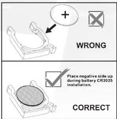
STEP 3
a) Carefully reinsert the BATTERY HOLDER (making sure the BATTERY HOLDER is the correct way around) until the BATTERY HOLDER - LOCKING TAB locks.


b) Check that the INFRARED REMOTE CONTROL is working correctly.
CONGRATULATIONS! And THANK YOU for selecting the BODYCRAFT VR500 Pro ROWER! Your choice reflects a wise investment in you and your family's health and wellness. We hope you use it for many healthy years!
For your safety and benefit, please read this entire manual. Please keep the manual in a convenient place for quick reference when needed. Bodycraft offers a complete array of high quality fitness equipment. Please refer to our web site at www.bodycraft.com to view more ways to enhance your lifestyle.
Your Bodycraft VR500 Pro ROWER has all the quality and design elements to make your workout extremely efficient and comfortable. Your new VR500 Pro ROWER is a serious cardio fitness machine that will keep you motivated, challenged and within reach of your fitness goals. The Bodycraft VR500 Pro ROWER will provide an efficient, low impact cardiovascular workout that will help improve energy levels and your quality of life. Cardiovascular training is vital for all ages and the Bodycraft VR500 Pro ROWER will provide an effective workout, producing results that will encourage you to reach your fitness goals and maintain the body you have always wanted. Spending 15 to 30 minutes a day, three times a week is all you needed to start seeing the benefits of a regular exercise program.
As a premium exercise equipment manufacturer we are committed to your complete satisfaction. If you have questions, suggestions or find missing or damaged parts, we guarantee your complete satisfaction through our authorized dealer network or by contacting us directly. Please call your local dealer or Bodycraft.
Phone: 800-990-5556 9am - 5pm EST Email: service@bodycraft.com
Recreation Supply, Inc.
7699 Green Meadows Dr.
Lewis Center, OH 43035
Purchaser's Reference Information:
IT IS IMPERATIVE THAT YOU FILL IN THE FOLLOWING INFORMATION AND REFER TO IT SHOULD THE NEED FOR SERVICE ARISE.
Product Name: VR500 Pro ROWER
Serial Number: RW ____

Proof of purchase must be supplied to validate warranty and the product must have been registered with Bodycraft via online at www.bodycraft.com or by calling 800-990-5556 or 740-965-2442 M-F 9 a.m-5 p.m EST.
The BodyCraft VR500 Pro Rower WARRANTY
BODYCRAFT warrants its products to be free of defects in material and workmanship for the time stated below to the original purchaser. This warranty is valid only in accordance with the following conditions:
• The warranty begins on the original date of purchase at retail and ends when the original owner disposes of it, either through sale, gift, or otherwise.
- This warranty is available only for purchases made within the USA and Canada, and currently residing in the USA or Canada.*
- In order for the warranty to be valid for the terms listed below, the product must be registered with BodyCraft within 30 days of purchase.
- The warranty is not transferable and does not cover normal maintenance.
- This warranty applies to Residential and Light Commercial use only and is void when used in a Full Commercial environment.
- This warranty does not cover damage resulting from accident, misuse, water, tampering, unreasonable use, unauthorized repairs, improper repairs, alterations or normal wear and tear.
- If the item exhibits such a defect, BODYCRAFT will, at its option, repair or replace it without cost for parts. Shipping and handling charges may apply. (BODYCRAFT may request a return of the part(s) or photographic evidence of the damaged part(s) prior to replacement at the owners expense).
- Proof of purchase must be supplied to validate warranty and the product must have been registered with BodyCraft via the included warranty card or online at www.bodycraft.com.
- This warranty is in lieu of all warranties, expressed or implied, and/or all other obligations or liabilities on our part and we neither assume nor authorize any person to assume for us any other obligation or liability in connection with the sale of the BodyCraft VR500 Pro Rower. Under no circumstances shall we be liable by virtue of this warranty or otherwise for damage to any person or property whatsoever for any special, indirect, incidental, secondary or consequential damage of any nature whatsoever arising out of the use or inability to use the BodyCraft VR500 Pro Rower.
• Residential: Frame: Lifetime, Parts: 7 Years, 2 Years Labor.
• Commercial (up to 5 hours a day) Frame: 10 Years, Parts: 3 years, Labor: 1 Year
* If you do not reside within the USA or Canada, please contact your local BODYCRAFT distributor for details specific to you.
** 5 hours or less of daily use.

- INTRODUCTION
- Congratulations!
- TABLE OF CONTENTS
- IMPORTANT INFORMATION - PLEASE READ
- Medical / Safety
- Care and Maintenance
- Components most Susceptible to Wear SEAT ROLLERS - ALUMINUM BEAM [part#001,118]
- DRIVE STRAP [part#709]
- FOOT REST Assembly
- [part#016,027,143,147,314A,367,386A,710]
- All FASTENERS [Nuts, Bolts, and Screws]
- General Information
- VR500-RW55 Pro Rower GENERAL PARTS IDENTIFICATION
- USING/OPERATING YOUR Bodycraft VR500 Pro Rower
- Unfolding
- Getting on Safely
- Heel Rest Adjustment
- Foot Strap Adjustment
- Computer Angle Adjustment
- Handlebar Holder
- Handlebar Remote
- Foot Strap Release
- Folding
- Transportation and Storage
- CORRECT ROWING GUIDE
- Over Reaching
- SOLUTION
- Rowing with Arms Bent
- Bent Wrists
- Pulling the Body to the Handle
- Flying Elbows
- Locking the Knees
- VR500 ROWER ASSEMBLY INSTRUCTIONS
- STEP1
- STEP 2
- STEP 3
- STEP 4
- STEP 5
- STEP 6
- STEP 7
- STEP 8
- STEP 9
- STEP 10
- STEP 11
- STEP 12
- ASSEMBLY COMPLETE
- STRETCHING
- DISPLAY DESCRIPTION
- KEY FUNCTIONS
- POWERING ON YOUR ROWER
- OPERATION
- MANUAL MODE
- PROFILE MODE
- INTERVAL MODE
- CUSTOM PROGRAM MODE
- WATT MODE
- WIRELESS HANDLEBAR CONTROLLER PAIRING
- UNITS OF MEASUREMENT SETTING
- INFRARED REMOTE CONTROL INSTRUCTIONS—REPLACING THE BATTERY
- CONGRATULATIONS! And THANK YOU for selecting the BODYCRAFT VR500 Pro ROWER! Your choice reflects a wise investment in you and your family's health and wellness. We hope you use it for many healthy years!
- Purchaser's Reference Information:
- The BodyCraft VR500 Pro Rower WARRANTY
Brand : BodyCraft
Model : VR500
Category : Rowing Machine