
ESD-CC1 - Clavier de contrôle CCTV Elmo - Free user manual and instructions
Find the device manual for free ESD-CC1 Elmo in PDF.


| Product Type | CCTV Control Keyboard |
| Brand | Elmo |
| Model | ESD-CC1 |
| Dimensions (W x H x D) | 300 mm x 65 mm x 175 mm |
| Power Supply Input Voltage | 12 VDC (-15% / +50%) |
| Power Consumption | 5 W |
| Communication Interfaces | RS485 (half-duplex), RS232 |
| Connectors | RJ-11 (6P6C) for RS485, 9-pin D-sub for RS232, DC jack |
| Maximum Devices Linked | 255 |
| Keyboard ID Range | 0, 240-254 |
| Password Protection | Yes, default password 0000 |
| Display | LCD panel with backlight |
| Control Functions | Speed Dome, OSD Camera, Zoom Lens, Multiplexer, Matrix (reserved) |
| Joystick | 7-speed variable speed control |
| Preset Points | Up to 128 per camera |
| Sequences | Up to 4 sequences, 32 steps each |
| Auto-Pan / Cruise | Yes, configurable |
| Alarm Input Support | 4 alarm inputs per dome, configurable |
| Software Upgrade | Via RS232 using PC |
| Safety Approvals | CE, FCC Class A |
| Operating Temperature | 0 °C to 40 °C |
| Storage Temperature | -10 °C to 60 °C |
| Humidity | 10% to 90% RH, non-condensing |
| Cleaning Instructions | Clean with a dry, soft cloth. Do not use liquids or aerosols. |
Frequently Asked Questions - ESD-CC1 Elmo
User questions about ESD-CC1 Elmo
0 question about this device. Answer the ones you know or ask your own.
Ask a new question about this device
Download the instructions for your Clavier de contrôle CCTV in PDF format for free! Find your manual ESD-CC1 - Elmo and take your electronic device back in hand. On this page are published all the documents necessary for the use of your device. ESD-CC1 by Elmo.
USER MANUAL ESD-CC1 Elmo
CCTV control keyboard
ESD-CC1
Users' Manual
Version 3.0
WARNING!
TO PREVENT FIRE OR ELECTRIC SHOCK, DO NOT EXPOSE THIS PRODUCT TO RAIN OR MOISTURE.

CAUTION! RISK OF ELECTRIC SHOCK DO NOT OPEN!


The lightning flash with the arrowhead symbol, within an equilateral triangle, is intended to alert the user to the presence of uninsulated "dangerous voltage" within the products enclosure that maybe of sufficient magnitude to constitute a risk of electric shock to persons.

The exclamation point, within an equilateral triangle, is intended to alert the user to the presence of important operating and maintenance (servicing) instructions in the literature accompanying the products.
WARNING!
This equipment generates, uses and can radiate radio frequency energy and if not installed and used in accordance with the instructions in this manual, may cause interference to radio communications. It has been tested and found to comply with the limits for a Class A computing device pursuant to subpart J of part 15 of FCC rules which are designed to provide reasonable protection against such interference when operated in a commercial environment. This equipment has also been tested and found to comply with the requirements for a CE Class A device safety standards.
Operation of this equipment in a residential area may cause interference, in which case the user is required to take all measures are necessary, at the user's expense, to correct the interference.
Table Of Contents
- General Introduction......4
- Front Panel & Real Panel....5
2.1 Front Panel....5
2.2 Rear Connector Panel....6
2.3 Switch setting on rear connector PCB 6
- Installation....7
3.1 RS485 cable....7
3.2 Cable connections....7
- Operations....8
4.1 Power On....8
4.2 Camera Control Mode....8
4.2.1 OSD Camera Setting....9
4.2.2 Joystick....9
4.2.3 Set Preset and Run Preset....9
4.2.4 Sequence setting and execution....9
4.2.5 Auto-Pan....10
4.2.6 Cruise....11
4.2.7 Zoom/Focus Lens Control....12
4.2.8 Camera settings (All camera settings)....12-15
4.3 System Setting Mode....15
4.3.1 System Linking....16
4.3.2 Set Keyboard ID....16
4.3.3 System Monitor Setting....16
4.3.4 RS-232 Baud Rate Setting....17
4.3.5 Date Setting....17
4.3.6 Time Setting....17
4.3.7 System Date/Time Correction....18
4.3.8 System Alarm List....18
4.3.9 Camera Type & Class....18
4.3.10 Key Press Beep....19
4.3.11 Alarm Reaction....19
4.3.12 Password Set....19
4.4 Multiplexer Control....19
4.5 The control and setting of Video Matrix Switcher....19
- Troubleshooting....20
Appendix A. RS485 Communication....21
A.1 Connector (RJ-11 6P6C)....21
A.2 ID Address Mapping....21
Appendix B. Technical Specifications....22
Appendix C. The Architecture of SuperMPX and SuperMMX....23-24
Appendix D. Commands Tree of Operating and Setting....25-26
Appendix E. Software upgrade....27
1. General Introduction
This control keyboard is 100% integrated with our full range CCTV series, or other products that are compatible with the DSCP protocol. Equipped with the most sophisticated control protocols, this high-tech keyboard will greatly enhance the efficiency of the overall CCTV system. It also effectively integrates our Triplex Multiplexer, High Speed Dome Camera and other CCTV devices into one powerful yet user-friendly solution.
Developed with the most advance data communication protocol-DSCP, this control keyboard is able to automatically detect peripheral devices for their model and capability. Together with advanced system integrating technology and user-friendly design, it provides real-time operating environment for monitoring and controlling in a multiple devices surveillance system.

flowchart
graph TD
    subgraph GROUP1
        A["Device 1"] --> B["MUX"]
        C["Device 2"] --> B
        D["Device 3"] --> B
        E["Device 4"] --> B
        F["Device 5"] --> B
        G["Device 6"] --> B
        H["Device 7"] --> B
        I["Device 8"] --> B
    end

    subgraph GROUP2
        J["Device 1"] --> K["MUX"]
        L["Device 2"] --> K
        M["Device 3"] --> K
        N["Device 4"] --> K
        O["Device 5"] --> K
        P["Device 6"] --> K
        Q["Device 7"] --> K
        R["Device 8"] --> K
    end

    subgraph GROUP14
        S["Device 1"] --> T["MUX"]
        U["Device 2"] --> T
        V["Device 3"] --> T
        W["Device 4"] --> T
        X["Device 5"] --> T
        Y["Device 6"] --> T
        Z["Device 7"] --> T
        AA["Device 8"] --> T
    end
2. Front Panel & Real Panel
2.1 Front panel

- Multiplexer mode.
- Matrix mode.(Reserved)
- Camera/Dome mode.
- System Setup key.
- Camera Function keys and Direction keys.
- Camera Menu key /Enter key: in Camera Control mode, press for 2 seconds will get OSD menu. In Camera Setup mode it functions as Enter key.
- LCD panel: display system status and set up dialogue. In power saving mode, the LCD backlight will be temporarily turned off (50% power saved). Simply press any key to exit power saving mode.
- Keyboard Lock (keep pressing for 3 seconds to lock/unlock the keyboard).
- Joystick
- Multiplexer or Matrix control keys.
- VCR remote keys with blue.
- Home key.
- Number keys and ENTER key.
- Function key. F1 is remote-reset function. F2 is lock/unlock device function. F3 is reserved currently. F4 is Dome speed test function.
- Lens control keys.
- Sequence setting keys including INS/DEL/ENDSEQ keys.
2.2 Rear connector panel

- RS-485 connector (please refer to Appendix A for detail definition).
- Power jack (12Vdc).
- RS232 9pin D-sub connector.
2.3 Switch setting on rear connector PCB
Warning! This operation is available for system installers only.
A. Release 4 screws on rear cover first.
B. Adjust switch S1, S2, S4 according to the application. As below:

S1 RS485 Setting H F Half-Duplex (Default, standard RS485)
H F Full-Duplex (Reserved, =RS422)
S2 RS232 Setting M □ S Slave mode (Default, used in download)
M ■ S Master mode (K.B control another device)
S4 RS232 Control N □ V Normal (Default, DTR/DSR function)
N □ V VCR control (RTS/CTS function)
3. Installation
3.1 RS485 cable
Cable Recommendation;
Connector: RJ-11 6P6C
Cable: Category 5
Max. Length: 1200 Meters
(Notice!! Detail Pin Definitions Please reference Appendix A.)

natural_image
Diagram of two Ethernet connectors with labeled pins (6 and 1), showing coiled cable structure without any text or symbols.3.2 Cable connections

flowchart
graph TD
    A["Video"] --> B["MUX"]
    C["Video"] --> B
    D["Video"] --> B
    E["RS485"] --> A
    F["RS485"] --> C
    G["RS485"] --> D
    H["Control keyboard"] --> I["Monitor"]
    J["1 2 3 4"] --> I
    K["5 6 7 8"] --> I
    L["9 10 11 12"] --> I
    M["13 14 15 16"] --> I
- Dome/Camera
Connect the RS-485 cables from cameras to keyboard. And connect the video cables to monitor or multiplexer.
(Caution! The ID address and video channel connection (of multiplexer) must follow the definition in Appendix A!)
• Video Multiplexer
Connect RS-485 to the keyboard directly or loop through the cameras.
4. Operations
4.1 Power On
After connecting all necessary cables, turn on the peripheral devices, and then connect DC12V adapter to the keyboard. The LCD will display the following message:
CCTV Controller
Version x.xx
Fig.4.1.1
Later, the keyboard will enter 'Stand By Mode'.
Stand By Mode:
CCTV Keyboard
2000/10/28 12:00:00
Fig.4.1.2
In the 'Stand By Mode', user can enter 'System Setting Mode' by pressing "SYS" key (section 3.4), or enter 'Camera Control Mode' by pressing Camera Select key (section 3.5), or enter 'Multiplexer Control Mode' by pressing Multiplexer Select key (section 3.6), or enter 'Matrix Control Mode' by pressing Matrix Select key MX (section 3.7).
4.2 Camera Control Mode
When the keyboard is in Stand By Mode, you can select any active camera by pressing Camera Select key, number key "1"\~"223" and then "ENTER" key or press # + 1(\~9) to choose the indexX camera of classX. The ID and device type of the selected camera will be displayed on LCD. P=Pan, T=Tilt, Z=Zoom, F=Focus, OSD=OSD available.
Camera Control Enter Camera No:xxx
Fig.4.2.1.1
Please input index for Class1 [01]
Fig.4.2.1.2
Now the keyboard is in Camera Control Mode, you can control all of the camera's functions in this mode.

Fig.4.2.2
The second row on the LCD allows users to input number 1\~255, it's used to specify preset point or the other camera parameters. Detail operation will be described in the following sections. Please refer to camera's manual to understand the function of each camera.
4.2.1 OSD camera setting
If the camera selected is equipped with OSD function, you can press “CAMERA MENU” key to get the OSD menu on the monitor. Then you can use the four direction keys to setup the parameters of the camera.
4.2.2 Joystick
The joystick is used to control Speed Dome Camera viewpoint (Pan/Tilt position). Normally, the Speed Dome Camera supports hemispheric viewpoints (Pan 360° and Tilt 90°). The speed of the dome movement depends on the angel of the Joystick, the more you push the Joystick, the faster the dome will move. The maximum speed when using Joystick is limited to get better control of the dome camera, there are 7 different speeds available.
4.2.3 Set Preset and Run Preset
Under the Camera Control Mode, you can key in a number (1\~128) and press “SET PRESET” key, the keyboard will ask the dome to store current position as a ‘Preset’. You may also key in the number and press “GO PRESET” key to ask the dome to move to that specific preset point.

Fig.4.2.3
4.2.4 Sequence setting and execution
The dome camera allows you to program up to four sequences, each sequence contains 32 steps. When the keyboard is under the Camera Control Mode, you may input number 1\~4, and press “RUN SEQ” key. The dome will start touring that sequence, and show the following message on the LCD for a few seconds:

Fig.4.2.4.1
You can also input number 1\~4 and press "SET SEQ" key to edit the sequence contents. You may use "▲"/"▼" keys to scroll through all 32 steps, and use "◀"/"▶" keys to move the cursor to the items you want to edit.
xxx. PST SPD DWELL [001] [10] [000] Fig.4.2.4.2
A. The first three digit (xxx) indicate the step number.
B. PST means 'Preset Point', it is the preset point used for this step, range from 1 to 128.
C. SPD means 'Speed', it defines how fast the dome will move from previous step to this step, the number range from 1 to 15.
D. DWELL means the dwell time of this step. The number range from 1 to 127, and the unit is second.
If you want to insert a step in the sequence, you can press “INS” key, then key in the parameters in current position. If you want to delete a step in the sequence, just press “DEL” key, current step will be erased immediately.
After sequence editing is finished, you may use “ESC” or "ENDSEQ" keys to exit. The difference between these two keys is: pressing “ENDSEQ” will delete the steps behind current step; pressing “ESC” will keep every step effective.
4.2.5 Auto-Pan
Under Camera Control Mode, you can press "AUTOPAN" key to enter Auto Pan mode, the LCD will display:
Auto Pan mode:
3.0 AutoPan select: 1. Run 2. Setting
Fig.4.2.5.1
Press "1", the dome start to pan automatically, and the LCD will display:
xxx P/T/Z/F/OSD Cam Running AutoPan...
Fig.4.2.5.2
Press "2" allows you to edit the route of auto-pan. You have to move the dome to the start point, and press "Enter" key to confirm.
3.1 AutoPan Setting Enter for Start Pos.
Fig.4.2.5.3
Then move the dome to the end point and press “Enter” key to confirm.
3.2 AutoPan Setting Enter for End Pos.
Fig.4.2.5.4
And then you have to decide the pan direction and the pan speed:
3.3 Pan Direction RIGHT/LEFT: LEFT
Fig.4.2.5.5
3.4 AutoPan Speed (1-4):
Fig.4.2.5.6
4.2.6 Cruise
Under Camera Control Mode, you can press "CRUISE" key to enter Cruise mode, the LCD will display:
Cruise mode:
4.0 Cruise select: 1. Run 2. Setting
Fig.4.2.6.1
Press "1", the dome starts to cruise automatically, and the LCD will display:
Group[xx]Device[xxx] Running Cruise...
Fig.4.2.6.2
Press "2" allows you to edit the route of cruise. You have to move the dome to the start point, and press "Select Device/Enter" key to confirm.
4.1 Cruise setting Enter for Start Pos.
Fig.4.2.6.3
Then move the dome to the end point and press "Select Device/ Enter" key to confirm.
4.2 Cruise setting Enter for End Pos.
Fig.4.2.6.4
And then you have to press "Select Device/ Enter" key to save it.
4.3 Cruise setting Enter for Saving.
Fig.4.2.6.5
4.2.7 Zoom/Focus Lens control
In the ‘Camera Control mode’, you can control the lens using the ‘Lens Control Keys’ on the right hand side of the keyboard. These function keys include Zoom Wide/Tele, Focus Near/Far and Iris Open/Close and Auto Focus hot key.
4.2.8 Camera setting
Pressing "SETUP" key in Camera Control Mode will enter Camera Setting Mode, you can setup many features of the camera here. You have to key in the password first:
Camera Setting Mode
2.0 Camera Setting Enter password[____]
Fig.4.2.8
After you key in the correct password, you can use the "▲"/"▼" keys to scroll through these setup pages, and use "◀"/"▶" keys to change the setting. Use "ESC" key to exit after the configuration is finished.
4.2.8.1 Auto Turn-Around
The Auto Turn-Around function is useful for following a person who passes directly beneath the camera, the dome rotates 180 degrees if you keep holding the joystick. Menu 2.1 allows you to enable or disable this function.
2.1 Auto Turn-Around [OFF] ON
Fig.4.2.8.1

flowchart
graph TD
    A["Initial Person"] --> B["Circular Object"]
    B --> C["Red Arrow"]
    C --> D["Two Business Figures"]
    D --> E["Final Product"]
4.2.8.2 Zoom speed setting
This item allows you to change the speed of zoom lens movement, use "◀"/"▶" keys to select Slow or Fast speed.
2.2 Zoom Speed
[SLOW] FAST
Fig.4.2.8.2
4.2.8.3 Digital Zoom ratio
This item allows you to change the digital zoom ratio from OFF (no digital magnify) to 8X (8 times digital magnify).
2.3 Digital Zoom X 2X
Fig.4.2.8.3
4.2.8.4 Alarm Setup
The dome camera is equipped with four alarm input connectors, Alarm1\~Alarm4. Once the alarm signal is detected, the dome camera will move to a preset viewpoint automatically. Menu 2.4 allows you to decide how the dome will react to the alarm inputs.
2.4 Alarm Setup Press Enter to Setup
Fig.4.2.8.4
Menu 2.4.1 decide how long the dome camera will stay in the alarm preset. This parameter is common for all the four alarm inputs.
2.4.1 Dwell Time: [010] sec
Fig.4.2.8.4.1
Menu 2.4.2 is the entry point for parameters related to Alarm1 input: ON/OFF (detect alarm signal or not), NC/NO (alarm signal type) and correspondent preset point for each Alarm input:

Fig.4.2.8.4.2

Fig.4.2.8.4.3

Fig.4.2.8.4.4
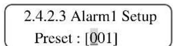
Fig.4.2.8.4.5
4.2.8.5 Speed by Zoom
When the lens is in Tele position, the pan/tilt speed is better slowed down to allow the user to trace the target smoothly. If you select ON here, the Pan/Tilt movement of the Dome will be proportional to the zoom ratio.

Fig.4.2.8.5
4.2.8.6 Set PAN bias

Fig.4.2.8.6
4.2.8.7 Set TILT bias
2.7 Set TILT bias [+1]
Fig.4.2.8.7
4.2.8.8 Check Camera Version
This item shows you the hardware and software version of the dome camera, it may be an useful information when you're checking with the installer for trouble shooting.
2.8 Camera Version H/W:Vx.x S/W:Vx.x
Fig.4.2.8.8
4.2.8.9 Auto Save Function.
The user can disable or specify the duration time of 1\~42 minutes to make a power-up default preset point for dome camera to go back after the operator stops moving the dome.
2.9 Auto Save Func. 01 Min.
Fig. 4.2.8.9
4.2.8.10 Line Lock Phase Adjust Function.
User should not use this function for detailed adjustment of camera module.
2.10 Llock Phase Adj. Press ◆ to - / +
Fig. 4.2.8.10
4.2.8.11 Receiver Auxiliary Switch Function.
Users can press 1 or 2 to select one of two receiver auxiliary switches and then press "◀" / "▶" key to turn on/off receiver auxiliary switch.
2.11 Receiver AUX Press 1/2 to setup
Fig. 4.2.8.11
2.11 Receiver AUX1 ON [OFF]
Fig. 4.2.8.12
4.3 System Setting Mode
If you press the "SYS" key and enter the correct password (default password is 0000), the keyboard will enter 'System Setting Mode'. Detail description of each item will be discussed in the following sections. Please use "▲" and "▼" keys to scroll through these setup pages.
![System Setting Mode: 1.0 System Setting Enter password [_______] Fig.4.3](/content/2026/05/957651/images/bfb764f96566a4216e9f8debf827fe95474cc69b57f3e6b0c22a3e1e18f3c89a.jpg)
4.3.1 System Linking
Menu 1.1 allow you to search for active cameras on the RS485 control bus again, press "◀" or "▶" key to start searching.
1.1 System Linking Press ◆▶ to search..
Fig.4.3.1
4.3.2 Set Keyboard ID
Menu 1.2 allow you to set up the ID number of this keyboard, use "◀" or "▶" key to change the number. The default ID is 000, if there are more than one keyboard in the same system, they must have different ID address to avoid communication conflict.
1.2 Set Keyboard ID (0 or 240-254):000
Fig.4.3.2
4.3.3 System monitor setting
When you use the keyboard to control devices, it needs Monitor to see the image to prevent wrong actions. There are four sources you can select, the first one is Multiplexer's main monitor output, the second one is Matrix's output, the third one is the SuperMPX mode, and the last one is SuperMMX mode.
When you select Item a.(as Fig.4.3.3.1), the image of camera will be displayed on Multiplexer's main monitor. On the other hand, when select Item b. (as Fig.4.3.3.2 and hit "ENTER"), please input the Output Channel/Monitor no. (as Fig.4.3.3.5) and hit "ENTER" key. The image of camera will be displayed on Matrix's monitor. Hit "ESC" to go back System mode.
Please refer Appendix C to see the architecture of SuperMPX and SuperMMX.

1.3 System Monitor a.MPX main monitor
1.3 System Monitor b.Matrix output
1.3 System Monitor c.SuperMPX mode
1.3 System Monitor d.SuperMMX mode
1.3.b Matrix output Monitor No.:[xxx]
Fig.4.3.3.5
4.3.4 RS-232 Baud rate setting
To select Item 4 (as Fig.4.3.4.1) and you can set RS232 Baud rate. The RS-232 protocol of keyboard is the standard 8,N,1. It provides three Baud rate setting (9600 (default), 4800 and 2400 bps). It can be set on your request (as Fig.4.3.4.1, 4.3.4.2, 4.3.4.3). Hit "◀"/"▶" key to select baud rate and hit "ENTER" key). Hit "ESC" to go back System mode.
1.4 RS232 Baud rate a. Baud rate 9600bps
Fig.4.3.4.1
1.4 RS232 Baud rate b. Baud rate 4800bps
Fig.4.3.4.2
1.4 RS232 Baud rate c. Baud rate 2400bps
Fig.3.4.4.3
4.3.5 Date Setting
Select Item 5(as Fig.4.3.5.1) and hit "ENTER" key (as Fig.4.3.5.2), then you can set the correct date of keyboard. Please hit "◀"/"▶" key to select items (year, month and date) and input the correct numbers. The default date is local. Hit "ESC" to go back System mode.
1.5 Date setting Press ENTER to setup
Fig.4.3.5.1
1.5.1 Date setting Yr:xx Mon:xx Day:xx
Fig.4.3.5.2
4.3.6 Time Setting
Select Item 5(as Fig.4.3.6.1) and hit "ENTER" key (as Fig.4.3.6.2), then you can set the correct time of keyboard. Please hit "◀"/"▶" key to select items (hour, minute and second) and input the correct numbers. The default date is local. Hit "ESC" to go back System mode.
1.6 Time setting Press ENTER to setup
Fig.4.3.6.1
1.6.1 Time setting HH:xx MM:xx SS:xx
Fig.4.3.6.2
4.3.7 System Date/Time Correction
Select Item 8(as Fig.4.3.7.1) and hit “ENTER” key (as Fig.4.3.7.2), then you can adjust all the devices at same time. Before you adjust the system date/time. Please check the date/time of this keyboard and make sure it’s correct. Hit “ESC” to go back System mode.
1.7 DateTime Correct Press ENTER to proc.
Fig.4.3.7.1
1.7 DateTime Correct Send to all devices?
Fig.4.3.7.2
4.3.8 System Alarm List
Record the latest 10 Alarm information of the system bus.
1.8 Alarm list Press ENTER to view
Fig.4.3.8.1
x.00/00/00 00:00:00 Alarm camera ID:xxx
Fig.4.3.8.2
4.3.9 Camera Type & Class
This item allows you to assign protocol type for each camera in current group number. Use "◀" or "▶" key to change the setting, "▲" or "▼" key to choose the index and "AUTOPAN" or "CRUISE" key to choose the class.
1.9 CameraType&Class Press 1:Type 2:Class
Fig.4.3.9.1
1.9.1 Camera ID #001 [DSCP] Pelco-D Pelco-P
Fig.4.3.9.2
1.9.2 Class1 Index01 Name:Class1 [001]
Fig.4.3.9.3
4.3.10 Key Press Beep
The built-in buzzer will beep when the user press any valid key, this item allows you to turn the beep on or off. Use "◀" or "▶" key to change the setting.
1.10 Key Press Beep
[OFF] ON
Fig.4.3.10
4.3.11 Alarm Reaction
When the alarm input of the dome camera is triggered, the camera will send an alarm message to the keyboard. The keyboard can be programmed to react to the message by: 1. Buzzer beep, 2. link to that camera automatically (so operator can control that camera immediately), 3. switch the multiplexer to that channel in full screen.
These reactions are disabled (OFF) by default. Menu 1.5 allows you to enable (ON) this function. Use "◀" or "▶" key to change the setting.
1.11 Alarm Reaction
[OFF] ON
Fig.4.3.11
4.3.12 Password Set
This item allows you to change the password, you have to enter the same number twice to confirm the change.
1.12.1 Password[****]
Fig.4.3.12.1
1.12.2 Password[****]
Confirm [ ]
Fig.4.3.12.2
4.4 Multiplexer Control
Under any mode, hit Multiplexer control key and input the Multiplexer's number then hit "ENTER" key (as Fig.4.4.1). Then, you can remotely control that particular Multiplexer. Please refer Multiplexer's manual to get the method of control and setting.
Multiplexer mode
Select MPX(1-16):xx
Fig.4.4.1
Select Camera CH:xx
Fig.4.4.2
4.5 The control and setting of Video Matrix Switcher
It is reserved now.
Under any mode, you can hit “Matrix” hot key to remote control the video matrix switcher. You can hit “ENTER” key to enter OSD control mode. You can hit “Direction”, “ENTER” and “ESC” keys to set all programs of Matrix. Please reference the Matrix’s manual to get the detail definition of Matrix.
5. Troubleshooting
When you get trouble with using the keyboard, please follow the procedures below to isolate the problem before call back to the installer.
A. Nothing or wrong text is displayed on LCD.
Possible causes and countermeasures:
a. No power or unstable power source: check the output of the DC12V adapter is correct or not.
b. Interference comes from peripheral devices: disconnect the RS-485/422 and RS-232 connectors and re-start the keyboard. If the keyboard works fine now, then we can conclude some of the other device cause the trouble, please connect the installer to solve the problem.
B. Device Link-up problem
Possible cause and treatment:
a. The keyboard RS-485 cable connection is not secure: please make sure the cable is firmly connected on both the keyboard side and device side.
b. Wrong start-up procedure: some peripheral devices (as P/T/Z/F dome cameras) need longer initial time after power on. They can not recognize the linking command during the initial time. Please make sure that all the peripheral devices have been powered-up before applying power on the keyboard.
c. RS-485 cable open or short: please separate each device and find out which segment of the communication you can connect single keyboard and device to confirm this possible cause. Please connect the concerning people and tell them this test result.
C. One or some devices lose control
Possible cause and treatment:
a. The bus does not connect to those peripheral devices: please check the RS-485 cables on those peripheral sides and make sure those cables are connected perfectly.
b. Malfunction of the peripheral devices: you can connect one keyboard to one device to confirm the proper functioning of the device.
c. One of the RS-485 cable segments open or short circuit: disconnect the cable segment and locate the failure segment. Please connect the installer for support.
Appendix A. RS485 Communication
A.1 Connector (RJ-11 6P6C)
| Pin No. | Definition | Direction |
| 1 | - | |
| 2 | +12V | in Power |
| 3 | GND | Power |
| 4 | DA | I/O |
| 5 | DB | I/O |
| 6 | - |

*pin 3,4,5 are basic connection, pin 2 is optional.
A.2 ID Address Mapping
A. System ID setting
| Item | ID address Device name | Remark | |
| 1 | 00H,0 Host controller Keyboard or computer | ||
| 2 | 01H–DFH, 1~223 Speed dome Total 223 Dome cameras | ||
| 3 | E0H–EFH, 224~239 Multiplexer | 224~239 ( Mpx1~Mpx16) | |
| 4 | F0H–FEH, 240~254 Control keyboard CCTV control keyboard | ||
| 5 | FFH, 255 | Matrix | |
B. Multiplexer (MPX) Channels and Camera ID Mapping
| MPX # | MPX ID | Camera ID | Remark |
| 1 E0H,224 | 01H – | 10H\ 1~16 Map to channel 1~16 of MPX | |
| 2 E1H,225 | 11H – | 20H\ 17~32 | |
| 3 E2H,226 | 21H – | 30H\ 33~48 | |
| 4 E3H,227 | 31H – | 40H\ 49~64 | |
| 5 E4H,228 | 41H – | 50H\ 65~80 | |
| 6 E5H,229 | 51H – | 60H\ 81~96 | |
| 7 E6H,230 | 61H – | 70H\ 97~112 | |
| 8 E7H,231 | 71H – | 80H\ 113~128 | |
| 9 E8H,232 | 81H – | 90H\ 129~144 | |
| 10 | E9H,233 | 91H – A0H\ 145~160 | |
| 11 | EAH,234 | A1H – B0H\ 161~176 | |
| 12 | EBH,235 | B1H – C0H\ 177~192 | |
| 13 | ECH,236 | C1H – D0H\ 193~208 | |
| 14 | EDH,237 | D0H – DFH\ 209~223 | Only 15 Dome can be connect |
| 15 | EEH,238 | None | Can connect to normal camera |
| 16 | EFH,239 | None | Can connect to normal camera |
Appendix B. Technical Specifications
The list is the specifications of CCTV control keyboard, our company reserve the right to modify the specifications.
| Item | Description | |
| System Control | Camera | Speed Dome Camera all function |
| OSD Camera all function | ||
| Zoom Lens Camera all function | ||
| Video Multiplexer All function | ||
| Video Matrix (reserved) | ||
| Linking capability 255 Devices(Maximum) | ||
| Signal | RS485(half-duplex), | |
| Power DC Jack, and terminal block Connectors | ||
| RS-485 RJ-11*2 (6P6C), and terminal block | ||
| RS-232 9pin D-sub, male | ||
| Power Supply | Input Voltage 12VDC(-15/+50%) | |
| Power Consumption 5W | ||
| Safety Approval CE,FCC | ||
| Dimension | Width | 300mm |
| Height | 65mm | |
| Depth | 175mm | |
| Environmental | Operation Temperature | 0°C ~ 40°C |
| Humidity 10%~90% RH, Non-condensation | ||
| Storage Temperature | -10°C~60°C | |
RS232
Appendix C. The Architecture of SuperMPX and SuperMMX
C.1 SuperMPX mode

flowchart
graph TD
    A["1 2 3 ...... 16 MPX#1 (ID=224)"] -->|MM| C["1 2 3 ...... 14 SuperMPX (ID=255)"]
    B["1 2 3 ...... 16 MPX#2 (ID=225)"] -->|...| C
    D["1 2 3 ...... 15 MPX#14 (ID=237)"] -->|MM| C
    E["#1 #2 #3 ...... #16"] --> A
    F["#17 #18 ...... #32"] --> B
    G["#208 ...... #223"] --> D
    C --> H["CCTV Monitor"]
    C --> I["..."]
    I --> C
C.2 SuperMMX mode

flowchart
graph TD
    A["1 2 3 ...... 16 MPX#1 (ID=224)"] -->|CM| C["1 2 3 ...... 14 SuperMMX (ID=255)"]
    B["1 2 3 ...... 16 MPX#2 (ID=225)"] -->|CM(Call Monitor)| C
    D["1 2 3 ...... 15 MPX#14 (ID=237)"] -->|CM| C
    E["CCTV Monitor"] -->|CM| C
    F["DOME ID"] --> A & B & C
    G["#1 #2 #3 .... #16"] --> A & B & C
    H["#17 #18 .... #32"] --> B & C
    I["#208 ...... #223"] --> D & C
Appendix D. Commands Tree of Operating and Setting
System
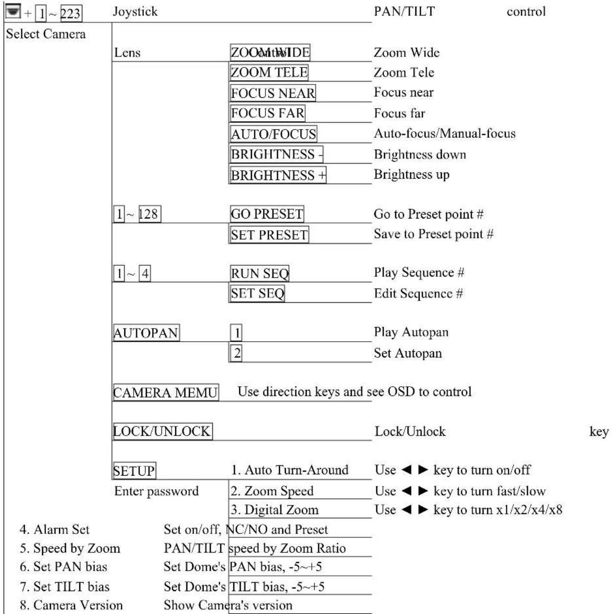

SYS
Enter password 1. System Linking Scan the exist device
System Setup 2. Set Keyboard ID Keyboard ID Setting 0,240-254
-
System Monitor MPX, MTX, SuperMPX, SuperMMX
-
RS232 Baud-rate set Use ◀▶ key to select 2400/4800/9600
-
Date setting Set Date: year, month, day
-
Time setting Set Time: hour, minute, second
-
System T/D correction System Time/Date correction
-
System Alarm List Record the latest 10 Alarm information
-
RS232/485 mode Use ◀▶ key to select RS232/485 mode
-
Key Press Beep Use ◀▶ key to turn on/off
-
Alarm Reaction Use ◀▶ key to turn on/off
-
Password Set new password
Appendix E. Software upgrade
The system installer can use a Personal Computer to download the upgrade software to the keyboard via RS-232 port. The download procedure is described below:
Warning! This operation is available for system installers only.
Step 1 Execute the Auto-unpack.exe on the computer
The program will create a sub-directory called “Keyboard” and unpack three files in the directory: Keyboard.exe, Keyboard.tsk and Readme.doc.
Please read the Readme.doc carefully before going on the download process.
Step 2 Connect the RS-232 cable
Please use a 9 pin one-by-one cable to connect the keyboard to the computer, and find out which communication port (COM1 or COM2) is used.
Step 3 Check S2 switch setting on the rear board
Refer to section 2.3 and make sure S2 (RS-232 setting) is on "S" (slave) position.
Step 4 Keep pressing "SETUP" key, and then power on the keyboard
The LCD will display “Ready to Download” message.
Step 5 Execute Keyboard.exe on the computer
The download process will start after you select the correct COM port number. It takes one or two minutes to finish. Please power off and on the keyboard after the download process is finished.
ELMO
1478 Old Country Road
Plainview, NY 11803
www.elmousa.com
- CCTV control keyboard
- ESD-CC1
- Users' Manual
- WARNING!
- Table Of Contents
- General Introduction
- Front Panel & Real Panel
- Front panel
- Rear connector panel
- Switch setting on rear connector PCB
- Installation
- RS485 cable
- Cable connections
- - Dome/Camera
- • Video Multiplexer
- Operations
- Power On
- Camera Control Mode
- OSD camera setting
- Joystick
- Set Preset and Run Preset
- Sequence setting and execution
- Auto-Pan
- Cruise
- Zoom/Focus Lens control
- Camera setting
- Auto Turn-Around
- Zoom speed setting
- Digital Zoom ratio
- Alarm Setup
- Speed by Zoom
- Set PAN bias
- Set TILT bias
- Check Camera Version
- Auto Save Function.
- Line Lock Phase Adjust Function.
- Receiver Auxiliary Switch Function.
- System Setting Mode
- System Linking
- Set Keyboard ID
- System monitor setting
- RS-232 Baud rate setting
- Date Setting
- Time Setting
- System Date/Time Correction
- System Alarm List
- Camera Type & Class
- Key Press Beep
- Alarm Reaction
- Password Set
- Multiplexer Control
- The control and setting of Video Matrix Switcher
- It is reserved now.
- Troubleshooting
- Appendix A. RS485 Communication
- A.2 ID Address Mapping
- Appendix B. Technical Specifications
- Appendix C. The Architecture of SuperMPX and SuperMMX
- C.1 SuperMPX mode
- Appendix D. Commands Tree of Operating and Setting
- Appendix E. Software upgrade
- Warning! This operation is available for system installers only.
- Please read the Readme.doc carefully before going on the download process.
- ELMO
Brand : Elmo
Model : ESD-CC1
Category : Clavier de contrôle CCTV