HD350-AP-161 - Sorbet maker Atosa - Free user manual and instructions
Find the device manual for free HD350-AP-161 Atosa in PDF.


| Product Type | Commercial Ice Maker (Cube Ice) |
| Model | HD350-AP-161 |
| Brand | Atosa |
| Ice Type | Cube Ice |
| Max Ice Production | 350 lbs/24hr (at 70°F ambient, 70°F water) |
| Dimensions (W x D x H) | 575 x 750 x 1780 mm |
| Weight | 123 kg |
| Power Supply | 110-120V / 60Hz, 870W |
| Minimum Circuit Ampacity | 10.3 A |
| Recommended Fuse/Breaker | 20 A |
| Refrigerant | R290 (150g) |
| Ambient Temperature Range | 50 – 110 °F (10 – 43 °C) |
| Water Temperature Range | 37 – 90 °F (3 – 32 °C) |
| Water Pressure Range | 15 – 70 psi |
| Clearance Requirements (air-cooled) | 5 cm left/right, 1 cm top |
| Condenser Cleaning | Monthly (air filter) |
| Cleaning/Sanitizing Frequency | Every 3 months |
| Ice Thickness Adjustment | Adjustable water probe (clockwise thicker, counterclockwise thinner) |
| Warranty | 2 years parts & labor, additional 3 years compressor |
| Accessories Included | User manual, water inlet hose, drain hose, obstruction panel, ice scoop |
Frequently Asked Questions - HD350-AP-161 Atosa
User questions about HD350-AP-161 Atosa
0 question about this device. Answer the ones you know or ask your own.
Ask a new question about this device
Download the instructions for your Sorbet maker in PDF format for free! Find your manual HD350-AP-161 - Atosa and take your electronic device back in hand. On this page are published all the documents necessary for the use of your device. HD350-AP-161 by Atosa.
USER MANUAL HD350-AP-161 Atosa
In order to provide the best service, ATOSA
Requests that please register your warranty online
At www.atosausa.com
For any service issues, please kindly contact us at
Email:service@atosausa.com
Or
Toll Free:1-855-855-0399
Please clean the filter frequently!
Please do not overload unit!
ICEMAKER END-USER MANUAL
Table of contents
- ICE MAKER....1
1.1. Safety Notices....1
1.2. Summary ...... 2
1.3. Installation......4
1.4. Operation....11
1.5. Maintenance....12
1.6. Service....16
- Ice Dispenser 19
2.1. General Information....19
2.2. Installation Instructions....19
2.3. Operation....22
2.4. Maintenance Disassembly 23
2.5. Customer Support....26
2.6. Commercial Ice Machine Warranty....28
1. ICE MAKER
1.1. Safety Notices
Please read this manual carefully before proceeding, otherwise, can result in death, serial injury or damage to the equipment.
□ Caution
Read this manual thoroughly before operating, installing or performing maintenance on the equipment. Failure to follow instructions in this manual can cause property damage, injury or death.
□ Notice
☐ The ice making machine is commercial equipment, which is only suitable for the proper location,
☐ The manufacturer shall not be liable for any loss caused by improper operation or usage.
☐ Installation and necessary shift work, must be handed over to have the corresponding knowledge workers in accordance with the local laws and regulations according to the manufacturer's instructi
☐ Proper installation, care and maintenance are essential for maximum performance and trouble free operation of your equipment.
□ Warning
This equipment contains high voltage electricity and refrigerant charge. Installation and repairs are to be performed by properly trained technicians aware of the dangers of dealing with high voltage elect and refrigerant under pressure. The technician must also be certified in proper refrigerant handling servicing procedures. All lockout and tag out procedures must be followed when working on this equipment.
☐ The ice maker is to be installed in accordance with the Safety Standard for Refrigeration Systems, ASHRAE 15 and shall not be installed in corridors or hallways of public buildings.
Component parts shall be replaced with like components and that servicing shall be done by factory authorized service personnel, so as to minimize the risk of possible ignition due to incorrect parts improper service.
1.2. Summary
The following data are for reference only
1.2.1. Model
| Model | YR140-AP-161 | YR280-AP-161 | YR450-AP-161 | YR800-AP-261 | HD-350 | AP-161 |
| Ice type | Half cube ice | Half cube ice | Half cube ice | Half cube ice | Cube ice | ice |
| Cooling style | Air Air Air Air | Air | ||||
| Power supply | 110-120V/ 60Hz | 110-120V/ 60Hz | 110-120V /60Hz | 220-240V /60Hz | 110-120V/ 60Hz | |
| Power(W) | 363 704 965 1700 | 870 | ||||
| Max Ice production(IBS/24hr) | 140lb | 280lb | 450lb | 800lb | 350 | |
| Dimension(mm) | 601*725*981 601 | *725*981 765*610 | *557 765*610*80 | 1 575*750*1780 | ||
| Weight(kg) | 65 | 70 | 57 | 90 | 123 | |
| Refrigerant | R290/90g | R290/90g | R290/150g | R404a/440g | R290/150g | |
| Using temp. range | 50-110 °F | 50-110 °F | 50-110 °F | 50-110 °F | 50-110 °F | |
| Water temp. range | 37-90 °F | 37-90 °F | 37-90 °F | 37-90 °F | 37-90 °F | |
| Water pressure range | 15~70Psi | 15~70Psi | 15~70Psi | 15~70Psi | 15~70Psi |
1.2.2. Ice production
YR140-AP-161 Ice production:
| AmbientTemp.WaterTemp. | Ice production(lbs/24hr) | ||
| 70F(21°C) 90 | F(32°C) 100F(38°C) | ||
| 70F(21°C) 142 | 105 90 | ||
YR280-AP-161 Ice production:
| AmbientTemp.WaterTemp. | Ice production(lbs/24hr) | ||
| 70F(21°C) 90 | F(32°C) 100F(38°C) | ||
| 70F(21°C) 283 225 201 | |||
YR450-AP-161 Ice production:
| Ambient Temp.WaterTemp. | Ice production(lbs/24hr) | ||
| 70F(21°C) 90 | F(32°C) 100F(38°C) | ||
| 70F(21°C) 460 415 385 | |||
YR800-AP-261 Ice production:
| AmbientTemp.WaterTemp. | Ice production(lbs/24hr) | ||
| 70F(21°C) | 90F(32°C) 100F(38°C) | ||
| 70F(21°C) | 810 650 550 | ||
HD350-AP-161 Ice production:
| AmbientTemp.WaterTemp. | Ice production(lbs/24hr) | ||
| 70F(21°C) | 90F(32°C) 100F(38°C) | ||
| 70F(21°C) | 350 250 220 | ||
1.3. Installation
Installation Check List
□ Is the Ice Machine level?
□ Have all the electrical and water connections been made correctly?
□ Has the supply voltage been tested and checked against the rating on the nameplate?
☐ Is there proper clearance around the ice machine for air circulation?
☐ Is the ice machine grounded and polarity, correct?
☐ Has the ice machine been installed where ambient temperatures will remain in the range of 50^ - 110^ F (10 - 43°C)?
□ Is there a separate drain for the potable water, bin, and water-cooled condenser?
☐ Are all electrical leads free from contact with refrigeration lines and moving equipment?
☐ Has the owner/operator been instructed regarding maintenance and the use of the specified Cleaner and Sanitizer?
□ Has the owner/operator completed the warranty registration card?
□ Has the ice machine and bin been sanitized?
☐ Is the ice thickness control set correctly? (Refer to Operational Checks to check/set the correct ice bridge thickness).
1.3.1. Power supply
| Warning |
| All wiring must comply with national and local laws and regulationsThe ice maker must be earthed properly |
All electrical operations involved must comply with the following:
1) the ice maker must be grounded;
2) each ice maker must be individually fitted with fuses or breaker;
3) a qualified electrician must be needed with the wires;
4) the ice maker starts with the maximum load and the maximum allowable voltage fluctuates by 10%;
5) check that the socket is securely fastened before starting.
Match fuse or breaker and machine circuit current
| Model YR1 | 40-AP-161 YR28 | 0-AP-161 YR450 | -AP-161 YR800 | -AP-261 HD350-AP-161 | |
| V/P/F 110V/1/60Hz 110V/1/60Hz 110V/1/60Hz 230V/1/60Hz | 110V/1/60Hz | ||||
| Fuse/breaker | 10A | 16A | 20A | 25A | 20A |
| Min circuit current | 3.5A | 6.8A | 9.7A | 9.8A | 10.3A |
1.3.2. Construction
Ice machine head outside view
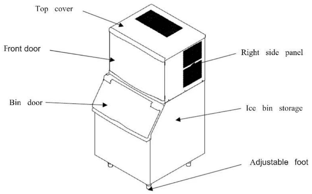
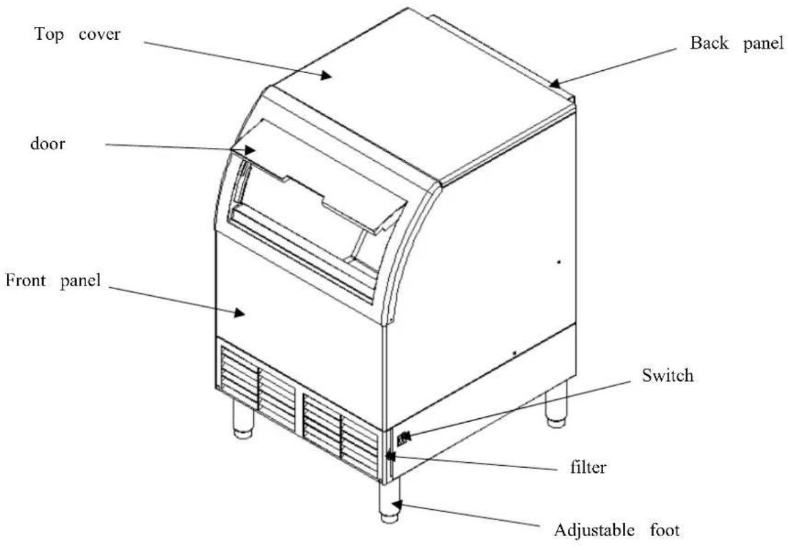
Self-contained ice machine construction
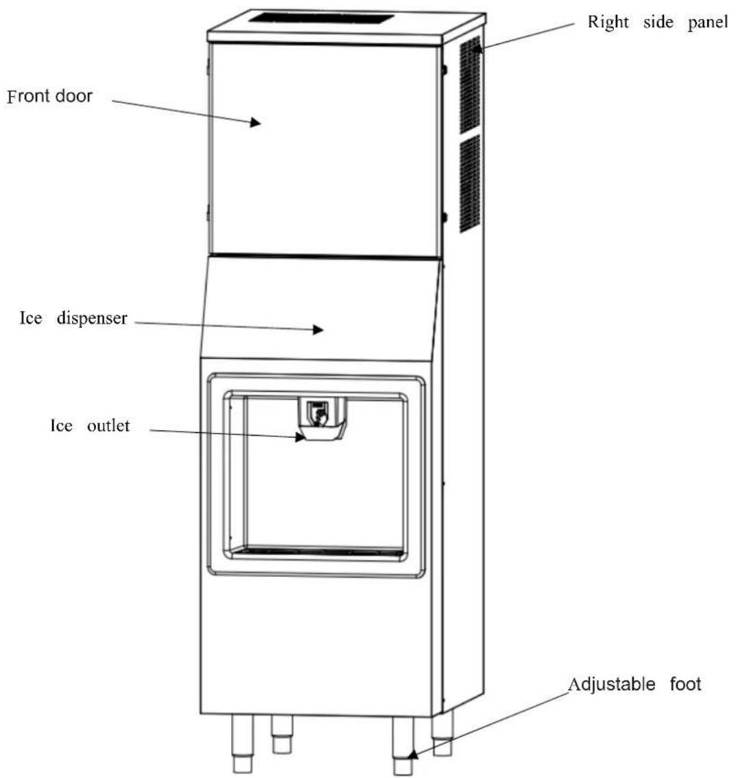
Ice maker with dispenser
1.3.3. Accessories
| Use manual 1 | |
| Water inlet hose 1 | |
| Drain hose 1 | |
| Obstruction panel 1 | |
| Ice scoop 1 |
User manual
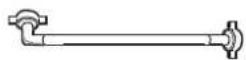
Water inlet hose

Drain hose
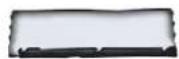
Air baffle (No in the self-contained machine)
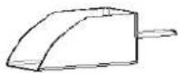
Ice scoop
1.3.4. Ice bin installation
□ Caution
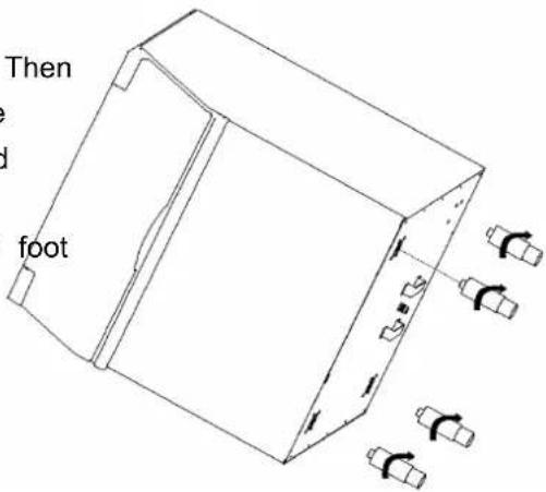
☐ Adjustive foot must be tightened; otherwise the ice machine will be instable.
1) carefully place the ice bin storage on the rear side. Then screw the four adjustable feet (accessories in the ice into the four holes at the bottom of the storage and screw them down hardly.
2) after the foot is installed, put it right, and adjust the foot slowly until the level.
1.3.5. Ice machine head installation
3) carefully remove the machine head paper packaging (do not upside down to prevent compressor damage), slowly lift the head, placed it on the ice bin storage.
4) slowly move the ice maker until it is in right place on the ice bin.
1.3.6. Obstruction panel installation (no in the self-contained machine)
□ Caution
☐ Air baffle must be installed, or affect heat reject.
1) Unscrew the two fixed screws;
2) put the air baffle as the picture shows;
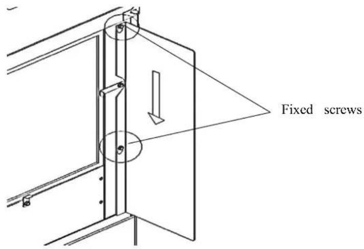
1.3.7. Connect the water inlet hose and drain hose
Ice machine head connection diagram
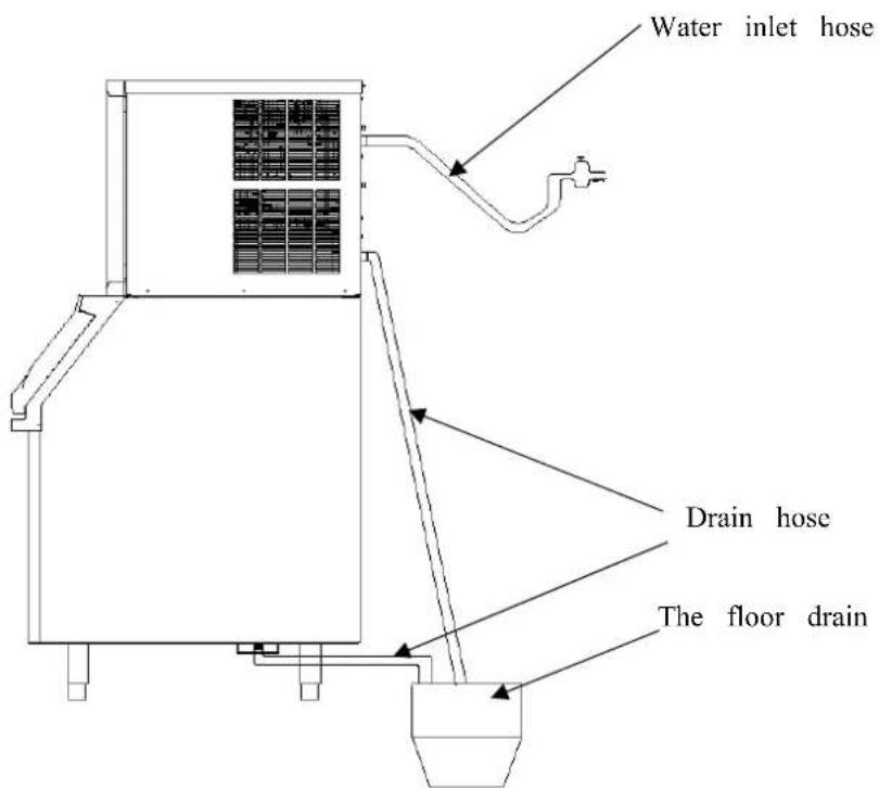
Self-contained machine water inlet hose installation
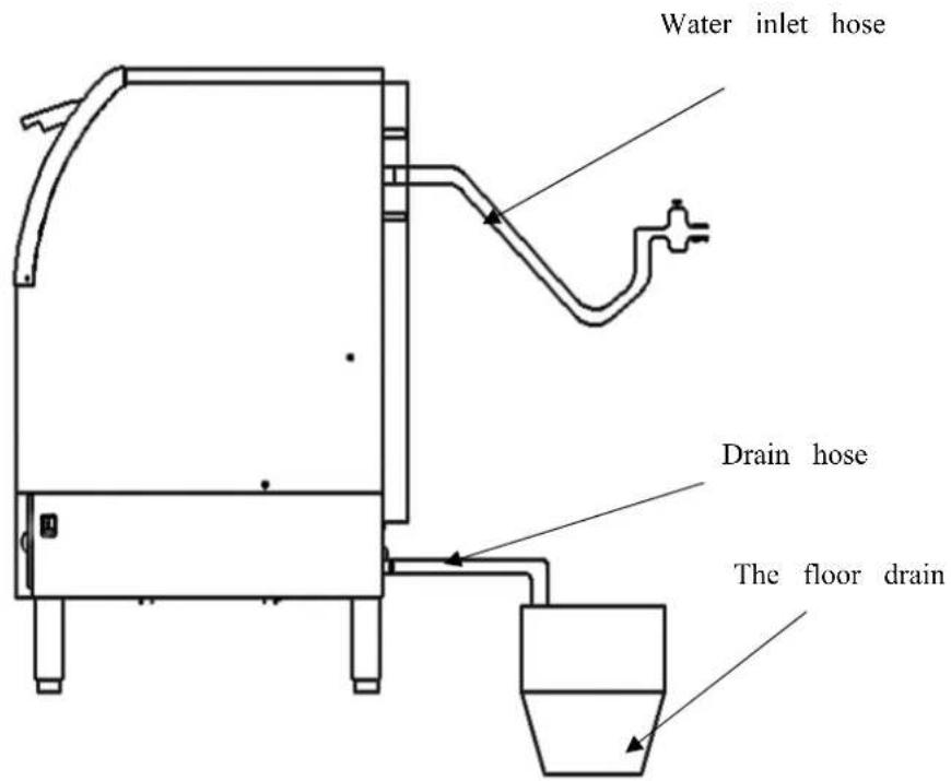
Notice
☐ The water entering the ice maker must meet the drinking water standard
1) if there is no water filter system, please connect the water inlet hose as diagram shows;
2) if the water pressure is greater than 80Psi, please install the relief valve
3) if the pressure is less than 20Psi, please install water pressurization;
Drain hose installation
| □ Notice |
| □ The water shall be prevented from flowing into the ice bin storage |
4) For the drain hose, each meter long going must have a drop of 2.5 cm.
5) The ice bin and the ice machine drains should be separated.
| Water inlet | Ambient | |
| Temperature. | 37-90 °F | 50-110 °F |
| Water pressure | 15-72Psi | |
1.3.8. Installation location
Notice
☐ Do not put things in the air inlet and outlet of the ice maker to prevent ventilation and heat reject.
☐ Do not install ice machine in direct sunlight.
1) the ice machine should be installed horizontally;
2) the ambient temperature should be 10\~43C(50—110F) and the water inlet temperature is 1\~32 C(33—90F);
3) For the self-contained ice maker:
Left and right side must have at least 5cm gap from the wall and the top has 1cm gap.
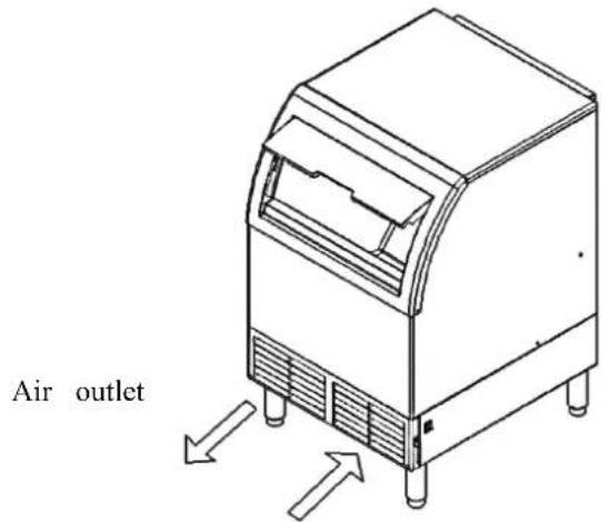
Air inlet
1.3.9. Water Filter Installation (Mandatory)
NOTICE
☐ To reduce the risk associated with property damage due to water leakage or flooding
Read and follow Use Instructions before installation and use of this system.
☐ Change the disposable filter cartridge at the recommended interval; the disposable filter cartridge must be replaced every 12 months or sooner.
☐ Failure to replace the disposable filter cartridge at recommended intervals may lead to reduced filter performance and failure of the filter, causing property damage from water leakage or flooding.
☐ Installation and use must comply with all state and local plumbing codes.
☐ Protect from freezing, remove filter cartridge when temperatures are expected to drop below 33^ F ( 4.4^ C).
☐ Do not install systems in areas where ambient temperatures may go above 110^ F ( 43.3^ C).
☐ Do not install on hot water supply lines. The maximum operating water temperature of this filter system is 100^ F ( 37.8^ C).
☐ Do not install if water pressure exceeds 125 psi (862 kPa). If your water pressure exceeds 80 psi (552 kPa), you must install a pressure limiting valve. Contact a plumbing professional if you are uncertain check your water pressure.
Do not install where water hammer conditions may occur. If water hammer conditions exist, you must install a water hammer arrester. Contact a plumbing professional if you are uncertain how to check it condition.
☐ Where a backflow prevention device is installed on a water system, a device for controlling pressure due to thermal expansion must be installed. Contact a plumbing professional if you are uncertain how to select/install/maintain a thermal expansion device.
☐ Where a booster pump is installed on a water system, you must maintain and inspect the attached
pressure switch regularly in accordance with the booster pump manufacturer's instructions. Contact a plumbing professional if you are uncertain how to maintain your booster pump system.
☐ Where a booster pump is installed on a water system, you must install an appropriate pressure relief valve. Pressure relief valve must be maintained and inspected every 6 months. Contact a plumbing professional if you are uncertain how select/install/maintain a pressure relief valve.
☐ Where a booster pump is installed on a water system, you must install an appropriate pressure regulating valve and regulate water pressure to 15-72Psi.
INSTALLATION
STEP 1 Remove system from the package and check parts NOTE: Be sure inlet water supply is turned off before installing.
STEP 2 Select the installation location. IMPORTANT: Allow a minimum of 3" (7.62 cm) of space below cartridge for change-outs.
STEP 3 Select fasteners (not included) and tools appropriate for the installation location (wood beam, concrete, etc.) IMPORTANT: The location and fasteners must support the weight of the system when full of water.
STEP 4 Draw a line using a level on the mounting surface.
STEP 5 Mark the locations for the fasteners either by measuring the distance between the bracket holes or by using the bracket itself.
STEP 6 Drill holes for the fasteners.
STEP 7 Allow 1/4"-3/8" (6-10 mm) of each fastener to protrude from the surface.
STEP 8 Install the head and bracket onto the fasteners.
STEP 9 Tighten fasteners.
STEP 10 (for systems using the NH3 head) Wrap male threads on nipple with PTFE tape (not included) and install into the inlet side of head (left). Install shut-off valve to nipple. IMPORTANT: Hexagonal sockets o head do not rotate.
STEP 11 Install inlet (left) and outlet (right) piping. Be sure to use PTFE tape. IMPORTANT: Hexagonal sockets on the head do not rotate.
STEP 12 Remove sanitary cap from cartridge. Install cartridge with a quarter turn to the right until the cartridge comes to a complete stop. (A "click" is heard on systems that use the NH3 head). Flush new cartridge as noted on the Flush Table on page 30.
STEP 13 (for systems using the NH3 head) Slowly turn on the inlet water supply. Be sure shut-off valve is in the "ON" position, and flush cartridges to remove any entrapped air and carbon fines from the cartridge. Refer to the Flush Table on page 30 for flush instructions. System is ready for use.
NOTE: Check system for leaks
1.4. Operation
1.4.1. Checklist before operation
a) Is ice machine level?
b) Are Water inlet and drain hose connected ok?
c) If there are not water lack with the ice machine?
d) Check the power voltage, if it matches the label on the machine?
1.4.2. operation
1) Freeze cycle
a) Power plug connection: the control board led is on.
b) startup: Toggle the switch to the on position, the green led will flash; the hot gas valve open for 10s, the compressor is energized,
c) ice melt: the hot gas valve still keep opening for 20s, then the water pump running to flush the evaporator for 20s, then close the hot gas valve and water pump and open the drain valve for 15s then close.
d) prechill (40s): the compressor is on, and the condenser fan and water inlet valve are energized, hot gas valve and water pump are closed, thus to prechill the evaporator.
e) Freeze: water pump is energized to make ice in the evaporator.
2) Harvest cycle
f) energy storage: when the harvest probe doesn't contact the water, condenser NTC probe test the liquid tube temperature and give the time to stop the condenser fan before harvest, to add of the refrigeration system. Increase the harvest effective.
g) Harvest cycle: hot gas valve is energized to heat the evaporator, when the surface of ice begin to melt, the ice will drop down by the gravity. And the ice put the water curtain outside and switch from close to open to close, harvest cycle ended to return the prechill cycle and star step.
h) Ice full: when the magnet switch opens beyond 30s in harvest cycle, the ice machine stops, mean the ice is full.
1.4.3. Ice weight per batch
| Modle YR140-AP-161 YR280- | AP-161 YR450- | AP-161 YR800- | AP-261 | |
| Ice Weight per batch(g) | 690—840 | 860—1050 | 1650--2000 | 3100--3750 |
1) When need to adjust the ice thickness, screws the water probe to change the water level position; the adjustable nut clockwise, increase the ice thickness; turn the adjustable nut counterclockwise, and reduce the ice thickness.
1.5. Maintenance
1.5.1. Clean and sanitize
Cleaning and Sanitizing GENERAL
You are responsible for maintaining the ice machine in accordance with the instructions in this manual. Maintenance procedures are not covered by the warranty. Clean and sanitize the ice machine every three for efficient operation. If the ice machine requires more frequent cleaning and sanitizing, consult a qualified service company to test the water quality and recommend appropriate water treatment. An extremely dirty ice machine must be taken apart for cleaning and sanitizing.
Warning
Wear rubber gloves and safety goggles (and/or face shield) when handling Ice Machine Cleaner or Saniti
CLEANING/SANITIZING PROCEDURE
This procedure must be performed a minimum of once every three months.
- The ice machine and bin must be disassembled cleaned and sanitized.
- All ice produced during the cleaning and sanitizing procedures must be discarded.
- Removes mineral deposits from areas or surfaces that are in direct contact with water. PREVENTATIVE MAINTENANCE CLEANING PROCEDURE
- This procedure cleans all components in the water flow path, and is used to clean the ice machine by cleaning/sanitizing procedure.
EXTERIOR CLEANING
Clean the area around the ice machine as often as necessary to maintain cleanliness and efficient operation. Wipe surfaces with a damp cloth rinsed in water to remove dust and dirt from the outside of the ice r greasy residue persists, use a damp cloth rinsed in a mild dish soap and water solution. Wipe dry with soft cloth.
The exterior panels have a clear coating that is stain resistant and easy to clean. Products containing a will damage the coating and scratch the panels.
- Never use steel wool or abrasive pads for cleaning.
- Never use chlorinated, citrus based or abrasive cleaners on exterior panels and plastic trim pieces.
Cleaning / Sanitizing Procedure
□ Warning
☐ Wear rubber gloves and safety goggles (and/or face shield) when handling Ice Machine Cleaner or Sanitizer.
Caution
☐ Do not mix Cleaner and Sanitizer solutions together. It is a violation of Federal law to use these solutions in a manner inconsistent with their labeling
□ Caution
☐ Never use anything to force ice from the evaporator. Damage may result.
Ice machine cleaner is used to remove lime scale and mineral deposits. Ice machine sanitizer disinfects removes algae and slime. For the cleaner and sanitizer, Ecolab company's products, Kay Delimer as the and kay5 as sanitizer are recommend.
NOTE: Although not required and dependant on your installation, removing the ice machine top cover ma easier access.
Step 1 Open the front door to access the evaporator compartment. Ice must not be on the evaporator during the clean/sanitize cycle. Follow one of the methods below:
- Toggle the switch on "off" position at the end of a harvest cycle after ice falls from the evaporator(s).
- Toggle the switch on "off" position and allow the ice to melt.
Step 2 Remove all ice from the bin/dispenser.
Step 3 Toggle the switch on "clean" position. Water will flow through the water dump valve and down the drain.
Wait until the water trough refills (approximately 1 minute), then add the proper amount of ice machine
| Model Amount of cleaner | |
| YR140-AP-161 2 pack | |
| YR280-AP-161 2 pack | |
| YR450-AP-161 4 packs | |
| YR800-AP-261 4 packs | |
| HD350-AP-161 4packs |
Step 4 Wait until the clean cycle is complete (approximately *30 minutes). Then disconnect power to the ice machine (and dispenser when used).
Step 5 Remove parts for cleaning. Please refer to the proper parts removal for your ice machine. Continue with step 6 when the parts have been removed.
Step 6 Mix the cleaner and lukewarm water. Depending upon the amount of mineral buildup, a larger quantity of solution may be required. Use the ratio in the table below to mix enough solution to thoroughly clean a
| water Mixed with cleaner | ||
| Cleaner solution rate 2L 4 packs | ||
Step 7 Use the cleaner/water mixture to clean all components. use a soft-bristle nylon brush, sponge or cloth (NOT a wire brush) to carefully clean the parts. Soak parts for 5 minutes (15 - 20 minutes for heavily Rinse all components with clean water.
Step 8 While components are soaking, use the cleaner/water solution to clean all foodzone surfaces of the ice machine and bin (or dispenser). Use a nylon brush or cloth to thoroughly clean the following ice.
- Side walls
- Base (area above water trough)
- Evaporator plastic parts - including top, bottom, and sides
- Bin or dispenser Rinse all areas thoroughly with clean water
SANITIZING PROCEDURE
Step 9 Mix a solution of sanitizer and lukewarm water
| water Mixed with sanitizer | ||
| Sanitizer solution rate 2L | 4 packs |
Step 10 Use the sanitizer/water solution to sanitize all removed components. Use a spray bottle to liberally apply the solution to all surfaces of the removed parts or soak the removed parts in the sanitizer/water solution
Step 11 Use the sanitizer/water solution to sanitize all foodzone surfaces of the ice machine and bin (or dispenser). Use a spray bottle to liberally apply the solution. When sanitizing, pay particular attention to the following areas:
- Side walls
- Base (area above water trough)
- Evaporator plastic parts - including top, bottom and sides
- Bin or dispense,
Step 12 Wait 20 minutes. Do rinse these surfaces with drinking water after sanitizing.
Step 13 Replace all removed components.
Step 14 Reapply power to the ice machine. Toggle the switch on "clean" position again. Water will flow through the water dump valve and down the drain. Wait until the water trough refills (approximately 1 minute), the proper amount of ice machine sanitizer
| Model | Amount of sanitizer |
| YR140-AP-161 | 1 pack |
| YR280-AP-161 1 pack | |
| YR450-AP-161 2 packs | |
| YR800-AP-261 2 packs | |
| HD350-AP-161 2 packs |
Use a measuring cup, put in 1L water with the correspondent sanitizer packs with the models, making t sanitizer solution to add the water trough.
Step 15 After when the sanitizing procedure finished, toggle the switch from clean to on position, close and secure the front door.
1.5.2. Parts Removal for Cleaning/Sanitizing
For Model YR450-AP-161, YR800-AP-261
1) Unscrew the front door
Unscrew the bottom two screws, get away the front door.
2) Remove the water dispense panel
3) Remove the water curtain
Unscrew the two thumb screws, remove the water curtain
4) Remove the water trough
For Model YR140-AP-161、YR280-AP-161
1) Remove the water curtain
2) Unscrew the two thumb screws, remove the water curtain
3) Remove the water dispense panel
4) Remove slides panel
5) Remove the water probe stand
6) Remove the water trough
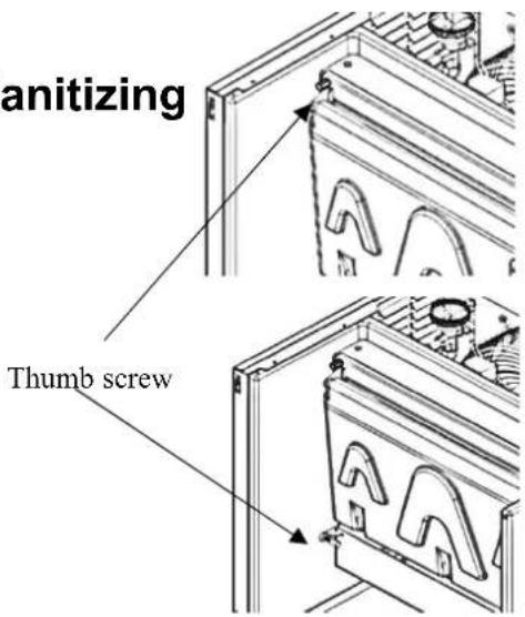
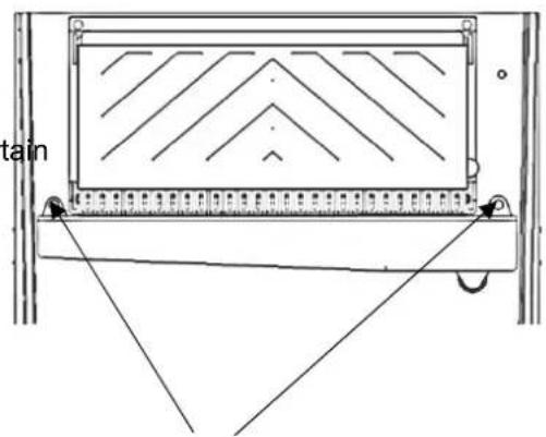
Thumb screw
1.5.3. Condenser air-filter wash
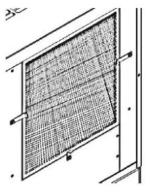
Remove the air-filter for cleaning.
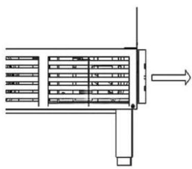
natural_image
Pure technical line drawing of a structural component with no text or symbolsYR140/YR280 YR450/YR800/HD350
natural_image
Technical line drawing of a grid-patterned panel mounted on a structural frame (no text or symbols)Notice
Clean air-filter once a month
1.6. Service
□ Important
Technicians must have the correlative certificate of service
1.6.1. Diagram
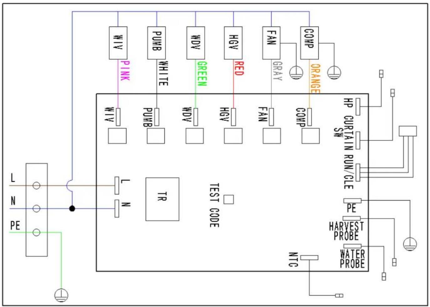
flowchart
graph TD
    A["PE"] --> B["L N PE"]
    B --> C["TR TEST CODE"]
    C --> D["PUMB PINK"]
    C --> E["PUMB WHITE"]
    C --> F["WDV GREEN"]
    C --> G["HGV RED"]
    C --> H["FAN GRAY"]
    C --> I["COMP ORANGE"]
    I --> J["HP CURTAIN RUN/CLE SW"]
    C --> K["PE HARVEST PROBE"]
    K --> L["WATER PROBE"]
    C --> M["NTC"]
    M --> N["Ground"]
    style A fill:#f9f,stroke:#333
    style B fill:#ccf,stroke:#333
    style C fill:#cfc,stroke:#333
    style D fill:#fcc,stroke:#333
    style E fill:#fcc,stroke:#333
    style F fill:#fcc,stroke:#333
    style G fill:#fcc,stroke:#333
    style H fill:#fcc,stroke:#333
    style I fill:#fcc,stroke:#333
    style J fill:#fff,stroke:#333
    style K fill:#fff,stroke:#333
    style L fill:#fff,stroke:#333
    style M fill:#fff,stroke:#333
1.6.2. Safety protection
1) E2: Long harvest cycle, harvest cycle reaches 4min for 100 times, stop.
2) E3: High pressure protection, discharge pressure reaches 450psi, stop.
3) E4: water lack protection, water probe can't touch water for 5min in freeze cycle, stop.
4) E5: condenser temperature alarm, condenser temperature beyond -20\~+80°C not stop, D10 (Led)flash fast.
1.6.3. LED indication
1) D7 green led: ice making indicator
D7 flash slow——1s on 1s off, ice making or ice full;
D7 flash fast—0.2s on 0.2soff, clean procedure end;
D7 Illuminate—clean procedure.
D7 off——switch on "off" position。
2) D8 blue led: water level indicator
D8 flash slow——1s on 1s off, E3, water lack protection.
D8 Illuminate—water probe touch the water
D8 off—water probe not touch the water
3) D9 red led: Harvest cycle indicator/ harvest probe
D9 flash fast—0.3s on 0.3s off, E1, long freeze protection
D9 flash slow—0.7s on 0.7s off, E2, long harvest protection
D9 Illuminate—harvest probe not touch the water
D9 off——harvest probe touch the water
4) D10 yellow led: water curtain switch indicator
D10 flash fast—0.3s on 0.3s off, E4, HP protection
D10 flash slow——1s on 1s off, E5, NTC temperature alarm
D10 Illuminate——water curtain switch close
D10 off——water curtain switch open
Failures analysis
1) Long freeze cycle:
a) High ambient temperature, high water inlet temperature;
b) Dirty condenser, clean the condenser
c) Harvest probe issue (short circuit)
d) Refrigeration system failure, call service call
2) Long harvest cycle:
a) Too thick for ice thickness; adjust the water probe
b) Dirty for evaporator, clean;
c) Ambient temperature is too low;
d) NTC probe issues
3) HP protection:
a) Dirty of condenser, clean;
b) Ambient temp. too higher;
c) HP switch is wrong, open; Fan motor issue, not run;
d) Refrigeration system failure, call service call;
4) Water lack protection:
a) No water supply
b) Water ball valve is closed
c) Water leak of the trough from somewhere
d) Water inlet valve issues
e) Water probe issues (short circuit)
1.6.4. Customer Support
Checklist
If a problem arises during operation of your ice machine, follow the checklist below before calling service adjustments and maintenance procedures are not covered by the warranty.
| Problem Possible Cause To Correct | ||
| Ice machine does not operate. | No electrical power to the ice machine and condensing unit | Replace the fuse/reset the breaker/turn on the main switch. |
| High pressure cutout tripping Clean condenser coil | ||
| Water curtain off or stuck open. | Water curtain must be installed and swinging freely | |
| Ice machine is not turned on. Put the switch in the ice "position" | ||
| Ice machine stops, and can be restarted by the switch. | Safety protection feature stopping the ice machine. | Refer to “Safety protection” on the last page |
| Ice machine does not release ice or is slow to harvest. | Ice machine is dirty Clean and sanitize the ice machine. | |
| Ice machine is not level. Level the ice machine | ||
| Low air temperature around ice machine head section | Air temperature must be at least 35°F (2°C) | |
| Ice machine does not cycle into harvest mode | The six-minute freeze time lock-in has not expired yet. | Wait for the freeze lock-in to expire. |
| Ice thickness probe is dirty Clean and sanitize the ice machine. | ||
| Ice thickness probe is short from the ground disconnect the probe to the ground | ||
| Ice thickness probe is out of adjustment | Adjust the ice thickness probe. | |
| Uneven ice fill (thin at the middle of evap) | Verify sufficient water level in sump trough. Conduct a qualified service company to check refrigeration system. | |
1.6.5. Waste disposal
Deal with the disposal of the ice machine and its accessories according to the Federal, state laws and regulations.
2. Ice Dispenser
2.1. General Information
2.1.1. Read This Manual
These instructions are provided to assist the qualified installer. Check your local Yellow Pages for the na nearest ATOSA distributor, or call ATOSA service; for information regarding start-up services.
2.1.2. Model Numbers
This manual covers the following models:
CYP160-161
These dispensers are designed to dispense both dice and half dice ice. These dispensers are used in with a ATOSA ice machine for automatic fill of dispenser.
- CYP160 Series Dispensers are capable of storing 160 lbs. of ice. The CYP160 accepts a single 22" I Dice size ice machine.
NOTE: Dispense Opening: Height 10.6" (27 cm), Width 15.7" (40cm)
2.2. Installation Instructions
2.2.1. Pre-Installation Checklist
☐ Location: Floor drain available – A floor drain for the dispenser should be available. We recommend that you vent the drain at the back of the dispenser to reduce buildup of algae and improve drainage. I should be 1/2" I.D. at minimum.
☐ Location: Avoid heat sources – Avoid placing the ice machine near heat sources such as radiators, heating vents and direct sunlight. Avoid placing air-cooled ice machines in kitchens, due to grease, fl other particles, which can collect on the condenser and fan blade, increasing ice machine maintenance reducing ice machine efficiency.
☐ Location: On a solid floor – The dispenser and ice maker should be sitting on a good, solid, level floor or surface.
☐ Location: Do not obstruct traffic – The dispenser should not extend from the wall in a way that obstructs traffic through the area.
Electrical – Proper electrical voltage is available. Receptacle is available and within six feet.
Warning
☐ Never use an extension cord. If an electrical outlet is not within six feet, have proper amperage outlet installed. The dispenser must be grounded in accordance with all local and national electrical codes.
Clearances for top and both sides of ice machine – Use clearances specified in the ice machine's Installation, Use and Care Manual.
☐ Clearance behind ice machine for dispenser and drains – The location must allow enough clearance for the water and drain connection at the rear of the dispenser.
☐ Back of ice machine to be flush with back of dispenser – This allows installation of the supplied mounting clip (metal plate) which secures the ice machine to the dispenser.
Separate drains – a separate drain line is required for the ice machine, in addition to a drain line for the Dispenser. Vent all drain lines.
☐ Water filtration – Water filtration is strongly recommended in order to increase the performance of the ice machine and reduce maintenance costs.
For full information about ice machine installation, including plumbing lines, connections and electrical requirements, see the ice machine installation manual.
2.2.2. Electrical
ICE DISPENSER CIRCUIT
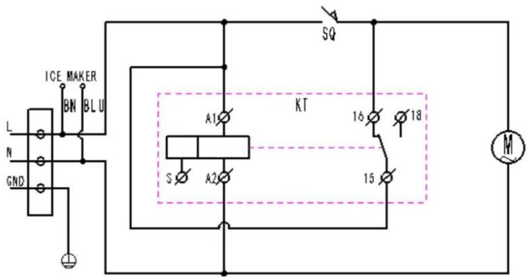
- In case of failure to prevent electric shock accidents of ice making machine, please professional maintenance.
● The color is for reference only, if there is any design change without prior notice.
□ Warning
☐ All wiring must conform to local, state and national codes.
SPECIFICATIONS
Electric Voltage - Cycle - Amp.* 115V60Hz,2.4A
| Motor Horsepower 1/7HP | |
| Fuse Size 15 amp maximun | |
| Operating Temperature Range 50°F minimum - 110°F maximum (10° - 43°C) | |
GROUNDING INSTRUCTIONS
□ Warning
☐ The dispenser must be grounded in accordance with national and local electrical codes.
This appliance must be grounded. In the event of malfunction or breakdown, grounding provides a path of resistance for electric current to reduce the risk of electric shock. This appliance is equipped with a cord equipment-grounding conductor and a grounding plug. The plug must be plugged into an appropriate outlet properly installed and grounded in accordance with all local codes and ordinances.
Warning
Improper connection of the equipment-grounding conductor can result in a risk of electric shock. The conductor with insulation having an outer surface that is green with or without yellow stripes is the equipment grounding conductor. If repair or replacement of the cord or plug is necessary, do not co the equipment-grounding conductor to a live terminal. Check with a qualified electrician or serviceman the grounding instructions are not completely understood, or if in doubt as to whether the appliance properly grounded. Do not modify the plug provided with the appliance — if it will not fit the outlet, proper outlet installed by a qualified electrician.
2.2.3. Installation Procedures
□ Warning
☐ Do not attempt to move a dispenser without first removing the ice machine. The combination can be unstable and could tip, causing serious injury.
- Review the Pre-Installation Checklist; then make sure all utility and space requirements are present at the installation site.
- Remove the carton top from the dispenser.
- Remove the legs and other accessories from inside the dispenser bin.
- Remove the dispenser from the shipping pallet.
- Flatten the shipping carton.
- Lay the dispenser on its back; on the carton.
- Thread the legs into the bottom of the dispenser.
- Set the dispenser upright.
- Place the dispenser in the desired location.
- Make sure the dispenser bin top is level. A level bin is important for proper operation of the ice n
- Place the ice machine on top of the dispenser at this time.
- Connect the drain of the dispenser to the floor drain.
- Follow local plumbing codes for drain installation.
- If the dispenser has a water valve, connect your water line to the water connection at the back of dispenser.
- Test all drain and water lines for leaks.
- Plug the dispenser into the proper electrical outlet.
-
Clean and sanitize all equipment. Follow cleaning and sanitizing instructions in this manual.
-
Adjust the ice machine according to the instructions provided with the ice machine.
- Install ice baffle inside the ice maker compartment. Follow installation instructions supplied with ice ba
- Install foam gasket on the bottom of the front panel.
- Fill the dispenser bin one quarter full of ice or start the ice machine, allowing the ice machine to three complete batches of ice.
- Test the ice dispensing action of the dispenser.
2.2.4. Installation Checklist
☐ Dispenser and ice machine are level?
Drains are vented?
☐ Dispenser does not sit in direct sunlight?
☐ Dispenser does not sit in direct airflow from a heating duct?
☐ Bin and ice machine drains are separate?
☐ Ice dispensed properly?
☐ Ice Machine ice thickness control is properly set?
2.3. Operation
2.3.1. Sequence of Operation
The operation of the ice dispenser can be divided into three main operations. They are Dispenser Activa Pick-Up and Ice Delivery.
DISPENSER ACTIVATION
- Rocking Chute (Push for Ice) Activation – User pushes the Rocking Chute, which energizes a microswitch.
The energized microswitch engages the gear motor.
ICE PICK-UP
When the customer activates the dispenser, the gear motor inside the dispenser begins to turn.
The gear motor shaft is attached to the paddle wheel inside the bin of the dispenser. As the paddle w picks up ice from the dispenser bin. The paddle wheel will bring the pocket containing the ice to the to travel area.
ICE DELIVERY
When the paddle wheel pocket reaches the top of its travel, the ice falls from the paddle wheel to the opening of the dispenser bin. The bin chute then directs the ice to the door assembly dispensing 2-3 o second.
If the door closes before all the ice is dispensed, some ice may be held back by the door assembly. open, the ice will fall through the door and the ice chute.
The ice chute will direct the ice into the customer's container.
NOTE: Dispense Opening: Height 10.6" (27 cm), Width 15.7" (40 cm)
2.3.2. Agitation Timers
The agitation timer is standard equipment for the floor standing dispenser. The purpose of the timer is t periodically agitate the ice in the bin to prevent congealing.
The timer is adjustable and is set to agitate the ice for three seconds every three and one half-hours. the dispenser will reset the timer. After 3.5 hours of non-use the timer will energize the dispenser motor. To check for correct function of the agitation timer, use the following procedure:
The agitation timer is located at the front of the dispenser in the control box, on the left side of the i
-
The timer will cycle every 55 seconds.
-
If the timer does not cycle every 55 seconds, replace the timer.
| ☐ Caution |
| ☐ Never operate with jumper removed. Damage will occur. |
2.4. Maintenance Disassembly
REMOVING THE FRONT PANEL
| Warning |
| Electric Shock Hazard |
| Unplug unit before servicing or cleaning. The agitator is operated by a timer and can agitate at any |
-
Shut off water to ice machine.
-
Loosen the 4 screws with a Phillips screwdriver.
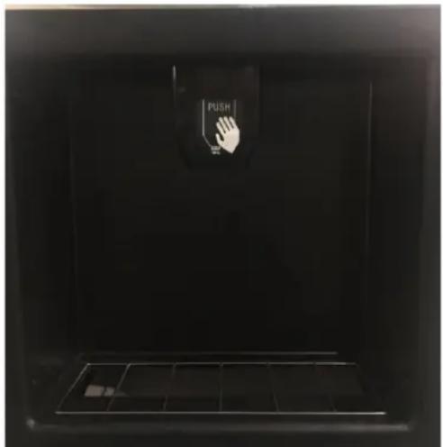
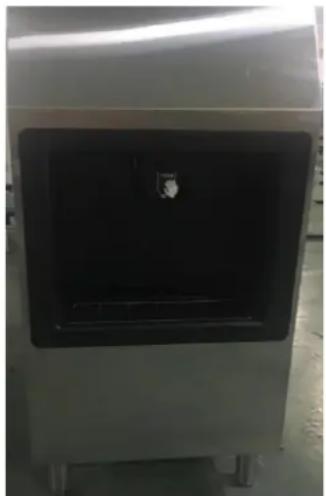
natural_image
Close-up of a metallic industrial machine with a black square panel and a small inset showing a white object (no visible text or symbols)Remove Screws to Disengage Door Put the panel up from the bottom
- Remove the black front panel.
- Lift the front panel off the catch hooks and set the panel aside.
DISASSEMBLING THE ROCKING CHUTE/DOOR & PADDLE WHEEL GUARD
| Warning |
| Electric Shock HazardUnplug unit before servicing or cleaning. |
- Remove the front panel from the dispenser. (See "Removing the Front Panel".)
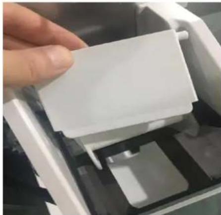
- Remove door lock.
natural_image
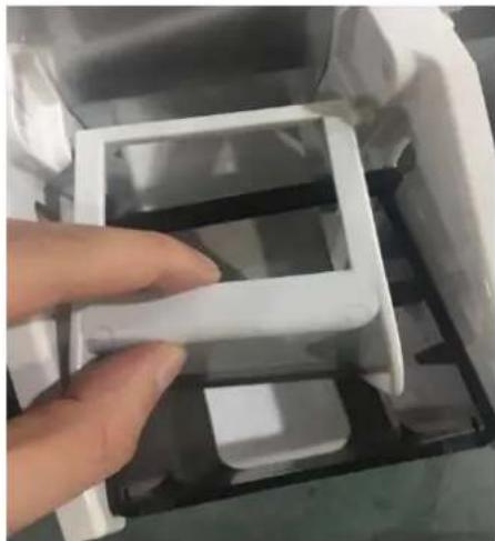
Close-up of a hand inserting a white plastic clip into a mechanical device (no visible text or symbols)- Remove Limit bracket
natural_image
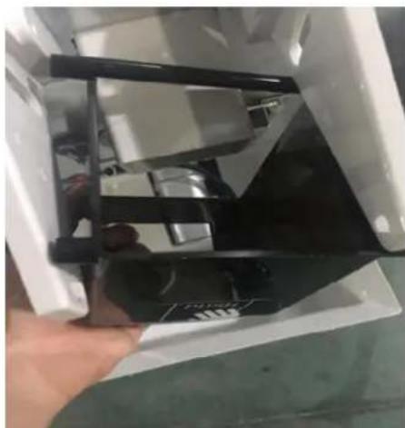
Hand holding a white plastic tray inside a transparent container, with other containers partially visible (no text or symbols)- Remove Push plate
natural_image
Close-up of a hand holding a black plastic device with a white frame, partially open (no visible text or symbols)□ Warning
☐ Unplug unit before servicing or cleaning.
☐ Ice dispenser bin contains moving parts that can move at any time and will cause injury if hands are in the way.
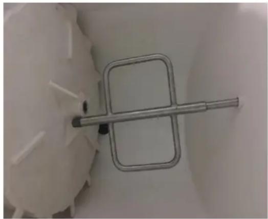
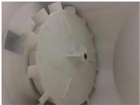
- These parts will be removed: agitator and paddle wheel.
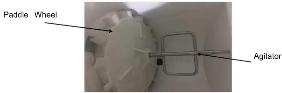
- Pull on the hand-removable agitator until it is clear of the agitator bushing.
natural_image
Close-up of a metallic mechanical component with a square end and central shaft, placed on a plain surface (no text or symbols visible)- Push the agitator toward the back of the bin until the agitator is free of the paddle wheel hub. Ren agitator by sliding to one side as you pull forward until the agitator shaft clears the bushing.
natural_image
Close-up of a white plastic mechanical gear with multiple teeth and central bore (no text or symbols visible)- Slide the paddle wheel from the motor shaft and remove.
2.4.1. Cleaning and Sanitizing
MONTHLY SANITIZING PROCEDURE
□ Warning
Electric Shock Hazard
☐ Unplug unit before servicing or cleaning.
- Remove the front panel, paddle wheel, ice chute and door assembly.
-
Mix a solution of 3 ounces (100 ml) Manitowoc cleaner per 1 gallon (4 liters) plain tap water.
-
Carefully clean all parts removed from inside the bin with this cleaner. Clean the dispenser bin, door and ice chute.
- Rinse all cleaned parts with fresh, running tap water.
- Mix a solution of 3 ounce (90 ml) special sanitizer with 4 gallons (15 liters) plain tap water.
- Sanitize each part washed in the previous step with this sanitizer solution. Sanitize and re-assemble in order:
Paddle wheel
Agitator
Ice chute assembly
Scrap ice tray
Front panel
- Do not rinse dispenser parts after they are sanitized. Allow parts to air dry.
- After all dispenser parts are replaced, restore power to the dispenser.
- Turn the ice machine on.
- Allow the ice machine to begin filling the dispenser.
- After three batches are in the dispenser, test the dispenser operation.
2.4.2. Removal of the Gearmotor
NOTE: The gearmotor does not have to be removed for cleaning/sanitizing.
□ Warning
Electric Shock Hazard
☐ Unplug unit before servicing or cleaning.
- Remove the front panel from dispenser.
(See "Removing the Front Panel".)
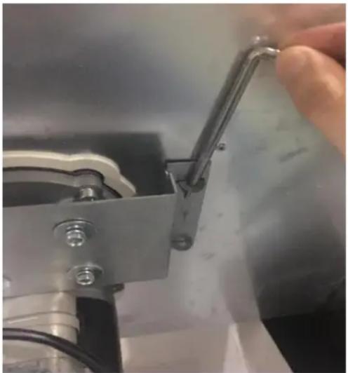
- Unplug the gearmotor wire.
natural_image
Close-up of a hand adjusting a metal clamp or bracket component (no visible text or symbols)- Pull the disassembly pin up.
- Grasp the gearmotor as the second pin is removed. Pivot the gearmotor out of place.
2.5. Customer Support
2.5.1. Checklist
If a problem arises during operation of your dispenser, follow the checklists below, before calling service. Routine adjustments and maintenance procedures are not covered by the warranty.
| Warning |
| Unplug unit before servicing or cleaning. Ice dispenser bin contains parts that can move at a will cause injury if hands are in the way. |
PROBLEM: ICE DOES NOT DISPENSE WHEN ROCKING CHUTE IS DEPRESSED
| Problem Possible Cause | To Correct | |
| Dispenser does not operate. | No electrical power to dispenser. | Plugged in? |
| Breaker tripped? | ||
| Check the cord and plug of the dispenser,Re record set if wire is broken. | ||
| Dispenser runs but does dispense ice. | No ice in bin. Add ice | to bin, have ice machine checked. |
PROBLEM: DISPENSER CRUSHES ICE AS IT DISPENSES
| Problem Possible Cause | To Correct | |
| Dispenser crushes ice as dispenses. | iThe ice in the bin is not proper size and type. | Replace with acceptable ice. |
| Is the ice being used a size piece of ice, i.e., are cubes full, not shallow, etc procedure. | Adjust ice machine cube size. Refer to ice machine Installation, Use and Care manual for procedure. |
PROBLEM: ICE CONTINUES TO DISPENSE OR DISPENSES BY ITSELF
| Problem | Possible Cause | To Correct |
| Dispenser agitates every 5 seconds. | The timer did not return to its default location | Call for Service. |
| Does ice continue to dispense after the up has been pulled away? | Does the gearmotor continue to run uring this time? | Call for Service. |
2.6. Commercial Ice Machine Warranty
2 YEAR WARRANTY
All claims for parts or labor must be made directly through Atosa. All claims must include: number of the unit, the serial number, proof of purchase, date of installation, and all pertaining information supporting the alleged defect. In case of compressor replacement under warranty, either compressor or compressor tag must be returned to Atosa along with above listed infoFailure to comply with warranty policies will result in voiding claims.
Two Year Parts & Labor Warranty
Atosa warrants all new refrigerated components, such as the cabinet and all parts, to be fixed defects in materials or workmanship. Atosa's obligation under this warranty is limited to a point two (2) years from the date of original installation or 27 months after shipment date from whichever occurs first. All parts covered under this warranty that are defective within two of original installation or twenty seven (27) months after shipment date from manufacturer, whichever occurs first, are limited to repair or replacement (including labor charges, of defect parts or assemblies). The labor warranty shall include standard straight time labor charges or reasonable travel time, as determined by Atosa.
Additional Three Year Compressor Warranty
In addition to the two (2) year warranty stated above, Atosa warrants its sealed compressor free from defects in both material and workmanship under normal and proper use and main service for a period of three (3) additional years from the date of original installation, but exceed five (5) years. Compressors that have been determined to be defective from Atosa this extended period will be either repaired or replaced with a compressor or compressor p similar design and capacity according to Atosa's discretion. The three (3) year extended compressor warranty applies only to sealed parts of the compressor and does not apply to other parts or components. This includes, the cabinet, paint finish, temperature control, refrig metering device, motor starting equipment, fan assembly, and other electrical components, etc.
R290 Compressor Warranty
The five-year compressor warranty detailed above will be void if the following procedure is carefully adhered to:
- This system contains R290 refrigerant and lubricant. The lubricant has rapid moisture absorbing qualities.
- Drier replacement is very important and must be changed when a system is opened for servicing.
- Micron level vacuums must be achieved to insure low moisture levels in the system.
- Compressor must be obtained through Atosa, unless otherwise specified in writing, through Atosa's warranty department.
What is Not Covered by This Warranty
Atosa's sole obligation under this warranty is limited to either repair or replacement of parts to the additional limitations below. This warranty neither assumes nor authorizes any person assume obligations other than those expressly covered by this warranty.
ROUTINE MAINTENANCE REQUIREMENTS MUST BE FOLLOWED OR WARRANTY IS VOI
Cleaning, Sanitation and Maintenance:
Ice machines require 3 types of maintenance: Removal of any build up of mineral scale from ice machines water system and sensors, sanitize the ice machine's water system and ice s-ig or dispenser and cleaning the condenser.
NO CONSEQUENTIAL DAMAGES: ATOSA IS NOT RESPONSIBLE FOR ECONOMIC LOSS; PROFIT LOSS; OR SPECIAL, INDIRECT, OR CONSEQUENTIAL DAMAGES, INCLUDING WITHOUT LIMITATION, LOSSES, OR DAMAGES ARISING FROM FOOD OR PRODUCT SPOILAGE, REGARDLESS OF WHETHER OR NOT THEY RESULT FROM REFRIGERATION FAILURE.
WARRANTY IS NOT TRANSFERABLE: This warranty is not assignable and applies only in of the original purchaser/user to whom delivered. ANY SUCH ASSIGNMENT OR TRANSFER SHALL VOID THE WARRANTIES HEREIN AND SHALL VOID ALL WARRANTIES, EXPRESS OR IMPLIED, INCLUDING ANY WARRANTY OF MERCHANTABILITY OR LABOR COVERAGE FOR COMPONENT FAILURE OR OTHER THE WARRANTY PACKET PROVIDED WITH THE UNIT.
ALTERATION, NEGLECT, ABUSE, MISUSE, ACCIDENT, DAMAGE DURING TRANSIT OR INSTALLATION, FIRE, FOOD, OR ACTS OF GOD: Atosa is not responsible for the repair replacement of any parts that are determined to have been subjected after the date of manufacture to alteration, neglect, abuse, misuse, accident, damage during transit or installation, fire, flood act of God.
IMPROPER ELECTRICAL CONNECTIONS: Atosa IS NOT RESPONSIBLE FOR THE REPAIR OR REPLACEMENT OF FAILED OR DAMAGED COMPONENTS RESULTING FROM ELECTRICAL POWER FAILURE, THE USE OF EXTENSION CORDS, LOW VOLTAGE, OR VOLTAGE DROPS TO THE UNIT.
THE TWO (2) YEAR PARTS & LABOR WARRANTY AND THE ADDITIONAL THREE (3) COMPRESSOR WARRANTY ARE AS DESCRIBED ABOVE. THESE WARRANTIES ARE EXCLUSIVE AND IN LIEU OF ALL OTHER WARRANTIES, INCLUDING IMPLIED WARRANTY AND MERCHANTABILITY OR FITNESS FOR A PARTICULAR PURPOSE. THERE ARE NO WARRANTIES WHICH EXTEND BEYOND THE DESCRIPTION ON THE FACE HEREOF.
Outside U.S. and Canada: This warranty does not apply to areas outside the continent of United States. Atosa is not responsible for any warranty claims made on products sold or used in such areas.
*In some cases, a 25% restocking fee may be charged to a buyer for returned items may at any time modify our equipment in order to provide and insure a superior pro Change is sometimes necessary to keep up with today's high standards in our industry. Atosa reserves the final interpretation of all public materials.
Model Number
Serial Number
Installation Date
- ICEMAKER END-USER MANUAL
- Table of contents
- ICE MAKER
- Safety Notices
- □ Caution
- □ Notice
- □ Warning
- Summary
- Model
- Ice production
- Installation
- Installation Check List
- Power supply
- Construction
- Ice maker with dispenser
- Accessories
- Ice bin installation
- Ice machine head installation
- Obstruction panel installation (no in the self-contained machine)
- Connect the water inlet hose and drain hose
- Notice
- Installation location
- Water Filter Installation (Mandatory)
- INSTALLATION
- Operation
- Checklist before operation
- operation
- 1) Freeze cycle
- 2) Harvest cycle
- Ice weight per batch
- Maintenance
- Clean and sanitize
- Cleaning and Sanitizing GENERAL
- Warning
- CLEANING/SANITIZING PROCEDURE
- EXTERIOR CLEANING
- Cleaning / Sanitizing Procedure
- Caution
- SANITIZING PROCEDURE
- Parts Removal for Cleaning/Sanitizing
- Condenser air-filter wash
- Service
- □ Important
- Diagram
- Safety protection
- LED indication
- Customer Support
- Checklist
- Waste disposal
- Ice Dispenser
- General Information
- Read This Manual
- Model Numbers
- CYP160-161
- Installation Instructions
- Pre-Installation Checklist
- Electrical
- SPECIFICATIONS
- GROUNDING INSTRUCTIONS
- Installation Procedures
- Installation Checklist
- Operation
- Sequence of Operation
- DISPENSER ACTIVATION
- ICE PICK-UP
- ICE DELIVERY
- Agitation Timers
- Maintenance Disassembly
- REMOVING THE FRONT PANEL
- DISASSEMBLING THE ROCKING CHUTE/DOOR & PADDLE WHEEL GUARD
- Cleaning and Sanitizing
- MONTHLY SANITIZING PROCEDURE
- Electric Shock Hazard
- Removal of the Gearmotor
- Customer Support
- Checklist
- Commercial Ice Machine Warranty
- YEAR WARRANTY
- Two Year Parts & Labor Warranty
- Additional Three Year Compressor Warranty
- R290 Compressor Warranty
- What is Not Covered by This Warranty
Brand : Atosa
Model : HD350-AP-161
Category : Sorbet maker