
VAR1 - Electrical relay Bogen - Free user manual and instructions
Find the device manual for free VAR1 Bogen in PDF.


| Product Type | Voice-Activated Relay (DPDT) |
| Power Supply | External 12V to 24V DC @ 100 mA (not included) |
| Input Selection | Slide switch for MIC or LINE (70V, 25V, 600 ohm) |
| Microphone Preamp Gain | 62 dB |
| Microphone Sensitivity | 750 mV RMS for 1 V RMS output |
| Microphone Frequency Response | 200 Hz to 10 kHz |
| Microphone Distortion | < 2% |
| Microphone Signal-to-Noise Ratio | 55 dB |
| Line Input Impedance | 600 ohms (line), 200k ohms (70V), 75k ohms (25V) |
| Line Input Frequency Response | 100 Hz to 10 kHz |
| Line Output Level | 400 mV RMS (70V), 420 mV RMS (25V) |
| Audio Output | Isolated 600-ohm transformer |
| VOX Sensitivity | 20 mV to 150 mV RMS @ 600 ohms line input |
| Time Delay Range | 0.25 to 25 seconds (adjustable) |
| Relay Contact Rating | 2 A / 30 V DC, 0.5 A / 120 V AC |
| Applications | Muting sound systems, activating security equipment, zone paging |
| Service | No user-serviceable parts; contact authorized Bogen service center |
| Warranty | 2 years from date of purchase to original purchaser |
Frequently Asked Questions - VAR1 Bogen
User questions about VAR1 Bogen
0 question about this device. Answer the ones you know or ask your own.
Ask a new question about this device
Download the instructions for your Electrical relay in PDF format for free! Find your manual VAR1 - Bogen and take your electronic device back in hand. On this page are published all the documents necessary for the use of your device. VAR1 by Bogen.
USER MANUAL VAR1 Bogen
The VAR1 Voice-Activated Relay is a DPDT relay device that is activated when an audio signal is detected at the microphone pre-amp or at 70V, 25V, or 600-ohm line level inputs. It has a number of useful applications, such as muting a sound system in response to a microphone or telephone page, activation of accessory (security) equipment, or activation of a zone paging module.
A slide switch is included to select the pre-amp or the line inputs. The VOX detect circuit also includes volume, sensitivity, and delay controls. The audio output is an isolated 600-ohm transformer. The unit operates from a DC power source (not included).
INSTALLATION
Set input source switch on the top side of the unit to LINE if using one of the line inputs or to MIC if using a microphone.
Connect a power supply to the 12 to 24V DC jack on the top of the unit or to the + and - screw terminals. The Bogen model PRS40C power supply is recommended.
WIRING
Refer to the block diagrams and the sample wiring diagrams on the next page to wire the VAR1 for your application.
OPERATION
Sensitivity can be adjusted according to the needs of the application. Clockwise rotation of the control increases sensitivity. Do not over rotate the control or you may damage the trimpot.
The delay control is also adjustable in the field. The maximum delay time is 25 seconds. Clockwise rotation of the control increases delay time.
SPECIFICATIONS
LINE INPUT
Impedance: 600 ohms
Frequency Response: 100 Hz to 10 kHz
70V Input Impedance: 200k ohms
Output Level: 400 m VRMS
25V Input Impedance: 75k ohms
Output Level: 420 m VRMS
MIC PREAMP
Gain: 62 dB
Sensitivity: 750 m VRMS for 1VRMS out
Distortion: <2%
Frequency Response: 200 Hz to 10 kHz
Output Signal-to-Noise Ratio: 55 dB
GENERAL
VOX Sensitivity: 20 mV - 150 m VRMS
@ 600 ohms Line input
Time Delay Range (approx.): 0.25 to 25 sec.
Relay Contact Rating: 2 amps/30V DC,
0.5 amp/120V AC
Power Requirements: External 12V to 24V DC @
100 mA (not included)
SERVICE
There are no user serviceable components within the VAR1. The warranty may become void if the unit is serviced by other than an authorized Bogen service agency.
Contact the Bogen Applications Department if you have any questions concerning VAR1 applications.
Limited Warranty; Exclusion of Certain Damages:
Bogen Voice-Activated Relay is warranted to be free from defects in material and workmanship for two (2) years from the date of sale to the original purchaser. Any part of any Bogen product covered by this warranty that, with normal installation and use, becomes defective (as confirmed by Bogen upon inspection) during the applicable warranty period, will be repaired or replaced by Bogen, at Bogen's option, provided the product is shipped insured and prepaid to: Bogen Factory Service Department, 50 Spring Street, Ramsey, NJ 07446, USA. Repaired or replacement product will be returned to you freight prepaid. This warranty does not extend to any of our products that have been subjected to abuse, misuse, improper storage, neglect, accident, improper installation or have been modified or repaired or altered in any manner whatsoever, or where the serial number or date code has been removed or defaced.
THE FOREGOING LIMITED WARRANTY IS BOGEN'S SOLE AND EXCLUSIVE WARRANTY AND THE PURCHASER'S SOLE AND EXCLUSIVE REMEDY. BOGEN MAKES NO OTHER WARRANTIES OF ANY KIND, EITHER EXPRESS OR IMPLIED, AND ALL IMPLIED WARRANTIES OF MER-
CHANTABILITY OR FITNESS FOR A PARTICULAR PURPOSE ARE HEREBY DISCLAIMED AND EXCLUDED TO THE MAXIMUM EXTENT ALLOWABLE BY LAW. Bogen's liability arising out of the manufacture, sale or supplying of products or their use or disposition, whether based upon warranty, contract, tort or otherwise, shall be limited to the price of the product. IN NO EVENT SHALL BOGEN BE LIABLE FOR SPECIAL, INCIDENTAL OR CONSEQUENTIAL DAMAGES (INCLUDING, BUT NOT LIMITED TO, LOSS OF PROFITS, LOSS OF DATA OR LOSS OF USE DAMAGES) ARISING OUT OF THE MANUFACTURE, SALE OR SUPPLYING OF PRODUCTS, EVEN IF BOGEN HAS BEEN ADVISED OF THE POSSIBILITY OF SUCH DAMAGES OR LOSSES. Some States do not allow the exclusion or limitation of incidental or consequential damages, so the above limitation or exclusion may not apply to you. This warranty gives you specific legal rights, and you may also have other rights which vary from State to State.
Products that are out of warranty will also be repaired by the Bogen Factory Service Department -- same address as above or call 201-934-8500. The parts and labor involved in these repairs are warranted for 90 days when repaired by the Bogen Factory Service Department. All shipping charges in addition to parts and labor charges will be at the owner's expense. All returns require a Return Authorization number. For most efficient warranty or repair service, please include a description of the failure.
Products manufactured and labeled by other companies may be covered by warranties offered by such companies. Please call Bogen Customer Service or refer to product packaging for manufacturer's warranty for non-Bogen branded products.
12/2008
VAR1used with amplifiers to mute music during a telephone page (paging port without contact closure).

flowchart
graph TD
    A["POWER SUPPLY"] --> B["VAR-1"]
    C["TELEPHONE SYSTEM PAGING PORT"] --> B
    B --> D["MOSS FET"]
    D --> E["AMPLIFIER"]
    E --> F["MUSIC"]
    B --> G["LINE INPUT"]
    B --> H["LINE VDC"]
    B --> I["POWER"]
    B --> J["MINIC INPUT"]
    B --> K["MINIC SOURCE"]
    B --> L["RELAY"]
    L --> M["AUX"]
    L --> N["MUTE"]
    L --> O["AUX"]
    B --> P["DATA INPUT"]
    B --> Q["DATA VDC"]
    B --> R["DATA POWER"]
    B --> S["DATA SENS"]
    B --> T["DATA DELAY"]
    B --> U["DATA VOUT"]
    B --> V["DATA R"]
    B --> W["T"]
    B --> X["R"]
    B --> Y["AUX"]
    B --> Z["MUTE"]
VAR1 used in a security system to activate an amplifier, CCTV, and light relay control.
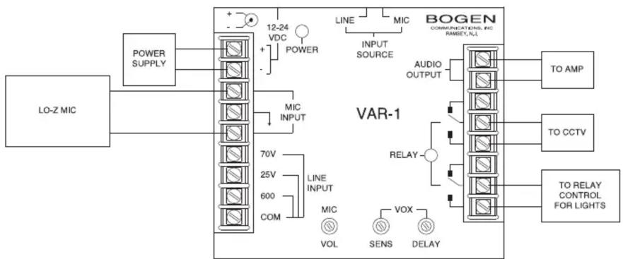
flowchart
graph TD
    A["LO-Z MIC"] --> B["POWER SUPPLY"]
    B --> C["VAR-1"]
    C --> D["TO AMP"]
    C --> E["TO CCTV"]
    C --> F["TO RELAY CONTROL FOR LIGHTS"]
    C --> G["TO RELAY CONTROL FOR LIGHTS"]
    C --> H["RELAY"]
    C --> I["LOGIC INPUT"]
    C --> J["LOGIC INPUT"]
    C --> K["LOGIC INPUT"]
    C --> L["LOGIC INPUT"]
    C --> M["LOGIC INPUT"]
    C --> N["LOGIC INPUT"]
    C --> O["LOGIC INPUT"]
    C --> P["LOGIC INPUT"]
    C --> Q["LOGIC INPUT"]
    C --> R["LOGIC INPUT"]
    C --> S["LOGIC INPUT"]
    C --> T["LOGIC INPUT"]
    C --> U["LOGIC INPUT"]
    C --> V["LOGIC INPUT"]
    C --> W["LOGIC INPUT"]
    C --> X["LOGIC INPUT"]
    C --> Y["LOGIC INPUT"]
    C --> Z["LOGIC INPUT"]
    C --> AA["LOGIC INPUT"]
    C --> AB["LOGIC INPUT"]
    C --> AC["LOGIC INPUT"]
    C --> AD["LOGIC INPUT"]
    C --> AE["LOGIC INPUT"]
    C --> AF["LOGIC INPUT"]
    C --> AG["LOGIC INPUT"]
    C --> AH["LOGIC INPUT"]
    C --> AI["LOGIC INPUT"]
    C --> AJ["LOGIC INPUT"]
    C --> AK["LOGIC INPUT"]
    C --> AL["LOGIC INPUT"]
    C --> AM["LOGIC INPUT"]
    C --> AN["LOGIC INPUT"]
    C --> AO["LOGIC INPUT"]
    C --> AP["LOGIC INPUT"]
    C --> AQ["LOGIC INPUT"]
    C --> AR["LOGIC INPUT"]
    C --> AS["LOGIC INPUT"]
    C --> AT["LOGIC INPUT"]
    C --> AU["LOGIC INPUT"]
    C --> AV["LOGIC INPUT"]
    C --> AW["LOGIC INPUT"]
    C --> AX["LOGIC INPUT"]
    C --> AY["LOGIC INPUT"]
    C --> AZ["LOGIC INPUT"]
    C --> BA["LOGIC INPUT"]
    C --> BB["LOGIC INPUT"]
    C --> BC["LOGIC INPUT"]
    C --> BD["LOGIC INPUT"]
    C --> BE["LOGIC INPUT"]
    C --> BF["LOGIC INPUT"]
    C --> BG["LOGIC INPUT"]
    C --> BH["LOGIC INPUT"]
    C --> BI["LOGIC INPUT"]
    C --> BJ["LOGIC INPUT"]
    C --> BK["LOGIC INPUT"]
    C --> BL["LOGIC INPUT"]
    C --> BM["LOGIC INPUT"]
    C --> BN["LOGIC INPUT"]
    C --> BO["LOGIC INPUT"]
    C --> BP["LOGIC INPUT"]
    C --> BQ["LOGIC INPUT"]
    C --> BR["LOGIC INPUT"]
    C --> BS["LOGIC INPUT"]
    C --> BT["LOGIC INPUT"]
    C --> BU["LOGIC INPUT"]
    C --> BV["LOGIC INPUT"]
    C --> BW["LOGIC INPUT"]
VAR1 for connecting a Paging Port to a ZPM3.

flowchart
graph TD
    A["POWER SUPPLY"] --> B["12-24 VDC"]
    B --> C["POWER"]
    C --> D["MIC INPUT"]
    D --> E["70V"]
    E --> F["25V"]
    F --> G["600 COM"]
    G --> H["LINE INPUT"]
    H --> I["MIC VOL"]
    I --> J["SENS"]
    J --> K["RELAY"]
    K --> L["VOX"]
    L --> M["DELAY"]
    M --> N["VAR-1"]
    N --> O["AUDIO OUTPUT"]
    O --> P["T R T1 R1"]
    P --> Q["ZPM3"]
VAR1Block Diagram

flowchart
graph TD
    A["MIC INPUT"] --> B["MIC PRE-AMP"]
    C["70V"] --> D["LINE"]
    E["25V"] --> D
    F["600 OHM"] --> D
    G["COM"] --> D
    H["MIC VOL"] --> B
    I["VOX DETECT"] --> J["RELAY"]
    K["AUDIO OUTPUT"] --> L["3M"]
    M["SENS"] --> N["RELAY"]
    O["DELAY"] --> P["RELAY"]
    Q["NC"] --> R["RELAY"]
    S["COM"] --> T["RELAY"]
    U["NO"] --> V["RELAY"]
    W["NC"] --> X["RELAY"]
    Y["COM"] --> Z["RELAY"]
- INSTALLATION
- WIRING
- OPERATION
- SPECIFICATIONS
- LINE INPUT
- MIC PREAMP
- GENERAL
- SERVICE
- Limited Warranty; Exclusion of Certain Damages:
- THE FOREGOING LIMITED WARRANTY IS BOGEN'S SOLE AND EXCLUSIVE WARRANTY AND THE PURCHASER'S SOLE AND EXCLUSIVE REMEDY. BOGEN MAKES NO OTHER WARRANTIES OF ANY KIND, EITHER EXPRESS OR IMPLIED, AND ALL IMPLIED WARRANTIES OF MER-
Brand : Bogen
Model : VAR1
Category : Electrical relay