TXFBB12 - Subwoofer AudioControl - Free user manual and instructions
Find the device manual for free TXFBB12 AudioControl in PDF.


| Product Type | Subwoofer Enclosure |
| Brand | AudioControl (Stinger) |
| Model | TXFBB12 |
| Subwoofer Size | 12 inches |
| Voice Coil Configuration | Single 2 ohm |
| Impedance | 2 ohms |
| Sensitivity (1W/M) | 87 dB |
| Frequency Response | 20 Hz – 250 Hz |
| RMS Power Handling | 200–600 watts (ideal 400W) |
| Recommended Amplifier Power | 200–600 watts @ 2 ohms |
| Speaker Model | SPC-12S2 |
| Enclosure Type | Sealed |
| Internal Volume | 0.706 cu ft (19.99 L) |
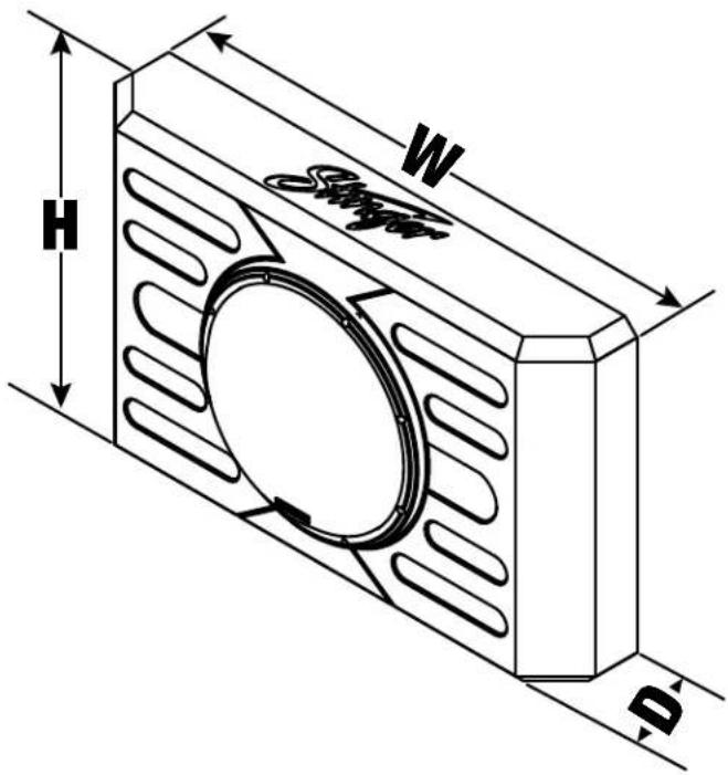
| Dimensions (H x W x D) without Speaker/Grill | 17 x 27.5 x 4.6 in |
| Dimensions (H x W x D) with Speaker/Grill | 17 x 27.5 x 5.8 in |
| Enclosure Weight | 16.25 lbs |
| Speaker Weight | 12.5 lbs |
| Total Weight (approx) | 28.75 lbs |
| Installation Location | Ford Bronco swing gate |
| Included Hardware | Mounting brackets, rivet nuts, bolts, hex keys, template, poly-fill |
| Warranty | 1 year limited |
Frequently Asked Questions - TXFBB12 AudioControl
User questions about TXFBB12 AudioControl
0 question about this device. Answer the ones you know or ask your own.
Ask a new question about this device
Download the instructions for your Subwoofer in PDF format for free! Find your manual TXFBB12 - AudioControl and take your electronic device back in hand. On this page are published all the documents necessary for the use of your device. TXFBB12 by AudioControl.
USER MANUAL TXFBB12 AudioControl
natural_image
Close-up of a black speaker grille with a circular vent and heart-shaped logo on the front panel (no text or symbols visible)12" SWING GATE MOUNTED SUBWOOFER ENCLOSURE FOR FORD BRONCO
INSTALLATION GUIDE
NOTE! Read this installation guide thoroughly before disassembling or modifying the vehicle. Installation of this product requires technical skill, experience and specialized tools. If in doubt, it's recommended to have it professionally installed by an authorized Stinger or AudioControl Dealer.
Limited Warranty
Stinger warrants this product to be free of defects in materials and workmanship for a period of one (1) years from the original date of purchase. This warranty is not transferable and applies only to the original purchaser from an authorized Stinger dealer in the United States of America only. Should service be necessary under this warranty for any reason due to manufacturing defect or malfunction, Stinger will (at its discretion), repair or replace the defective product with new or remanufactured product at no charge. Damage caused by the following is not covered under warranty: accident, misuse, abuse, product modification or neglect, failure to follow installation instructions, unauthorized repair attempts, misrepresentations by the seller. This warranty does not cover incidental or consequential damages and does not cover the cost of removing or reinstalling the unit(s). Cosmetic damage due to accident or normal wear and tear is not covered under warranty.
INTERNATIONAL WARRANTIES:
Products purchased outside the United States of America are covered only by that country's Authorized Stinger reseller and not by Stinger. Consumers needing service or warranty information for these products must contact that country's reseller for information.
INSTALLATION NOTES
■ For models equipped with a factory subwoofer, unplugging the factory subwoofer is recommended.
■ Some installation steps are more easily completed with a second person.
■ Speaker wire is required before the enclosure is mounted.
■ Recommended amplifier rating: 200-600 watts @ 2ohms.
■ Do not power up until inside contents are removed.
GETTING STARTED
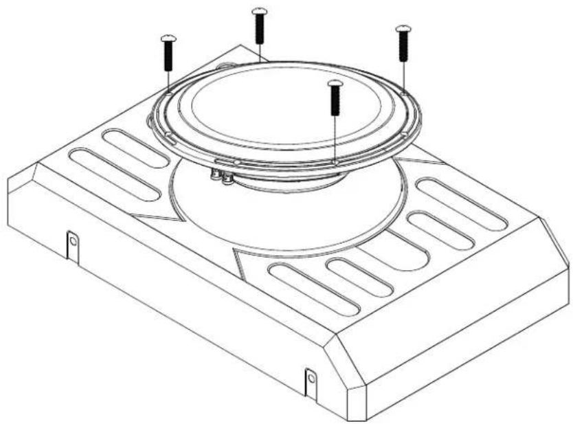
Remove the four Philips screws from the speaker and remove the speaker. Set speaker and screws in a safe place.
natural_image
Technical line drawing of a speaker or fan assembly with mounting holes and a central speaker (no text or symbols)Remove contents from inside the enclosure.
Open the hardware pack and confirm hardware quantities and tools required using the guide on the following pages.
RECOMMENDED TOOLS
2 Philips Screwdriver
5mm Allen Wrench
14mm Wrench
10mm Socket
Ratchet
Socket Extension
9mm Drill Bit (Included)
Drill
Center Punch
Hammer
Tape
Wire Strippers
Scissors
Rivet Nut Setter (Optional)
HARDWARE
B1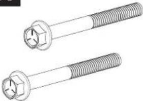 | B2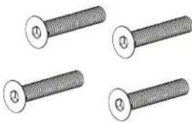 | 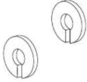 | 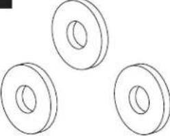 |
| M6 FLANGED HEX HEAD BOLT (2) 40mm / 1.57in Length | M6 ALLEN HEAD BOLT (4) 20mm / .78in Length | M6 SPLIT LOCK WASHER (2) 11mm / .43in Diameter | M6 METAL WASHER (3) 18mm / .71in Diameter |
W3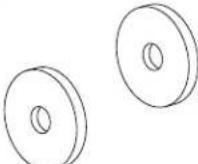 | L1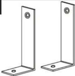 | L2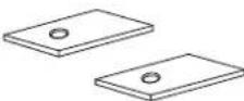 | T1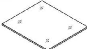 |
| M6 RUBBER WASHER (2) 18mm / .71in Length | BOTTOM L BRACKET (2) FOAM BRACKET PAD (2) MOUNTING TEMPLATE (1) | ||
B3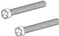 | N1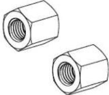 | W4 | R1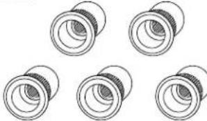 |
| M6 HEX HEAD BOLT (2) 40mm / 1.57in Length | M8 HEX NUT SPACER (2) | M6 TOOTH LOCK WASHER (2) | M6 RIVET NUT INSERT (5) |
P1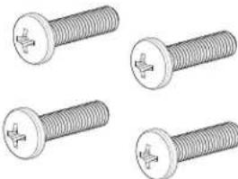 | P1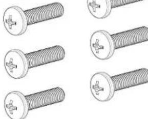 |  | |
| M5 PHILIPS HEAD SCREW (4) 30mm / .78in Length(Removed from speaker) | M5 PHILIPS HEAD SCREW (6) 30mm / .78in Length(Included in hardware) | POLY-FILL (1) | |
NOTE: Hardware images not to scale. There will be hardware left over depending on the installation
INSTALLATION
1
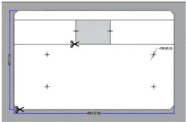
Using scissors or a straight edge and utility knife, cut out the template along the dashed lines.
2
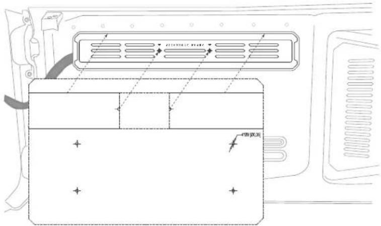
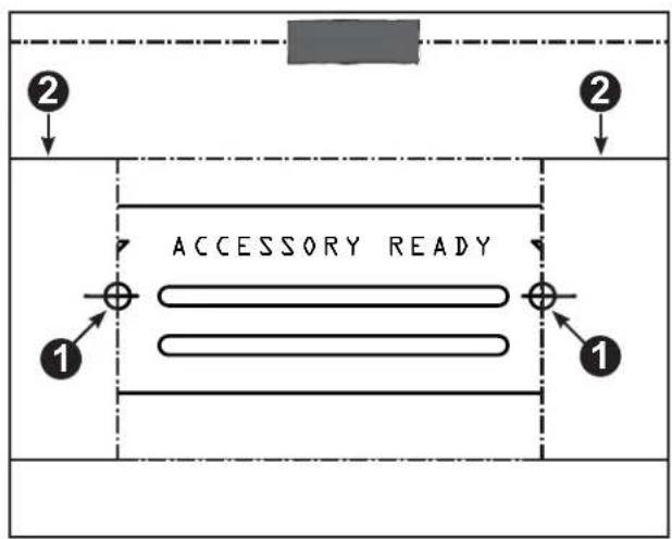
Position the template on the on the inside of the swing gate using the plastic trim panel as a guide as shown.
Align the left and right cross-hairs on the template to the register marks on the trim panel (1). Verify the template is straight by confirming the horizontal line on the template (2) follows the horizontal groove on the plastic trim panel.
Once aligned, securley tape the template to the swing gate.
flowchart
graph TD
    A["Section 1"] --> B["Section 2"]
    B --> C["Accessory Ready"]
    style A fill:#f9f,stroke:#333
    style B fill:#bbf,stroke:#333
    style C fill:#dfd,stroke:#333
INSTALLATION
3
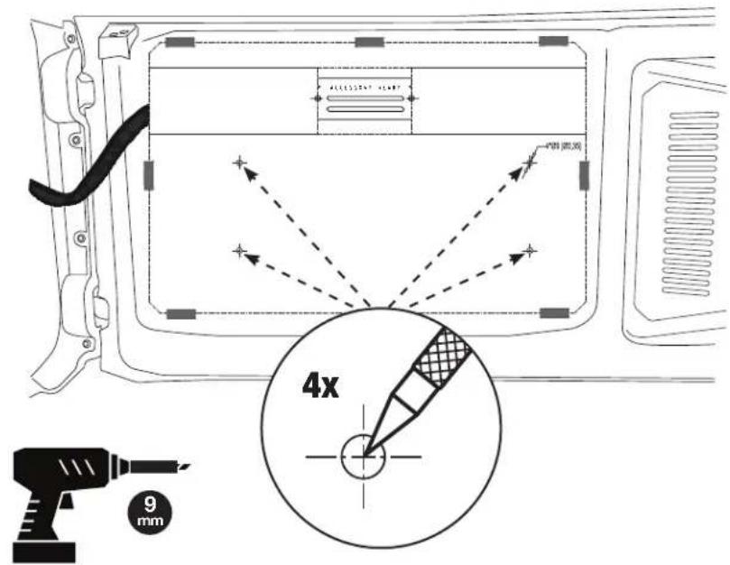
Using a center punch, mark the four mounting locations on the template.
Remove the template and drill pilot holes at the four locations.
CAUTION: To prevent the drill bit from hitting the outer side of the swing gate, wrap a significant amount of tape around the drill bit leaving only 12 " of the bit exposed.
Drill 9mm holes at the four marked locations.
4
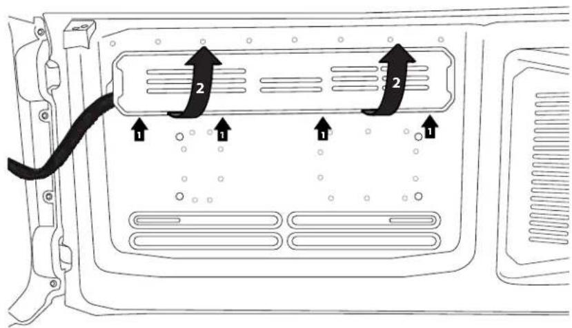
Remove the swing gate trim panel using a nylon panel tool or similar to release the retaining clips (1) along the bottom, then swing up (2) to release the locking tabs along the top.
INSTALLATION
5
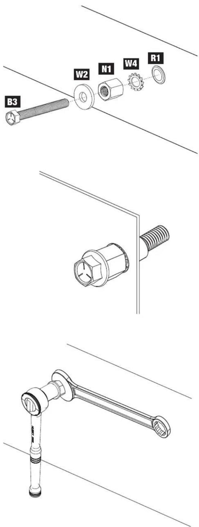
If a rivet nut setter is not available, follow the directions below for each of the four holes:
A. Insert a R1 rivet nut into the hole.
B. Slide an W2 metal washer, a N1 spacer nut and a W4 tooth lock washer onto one of the B3 bolts.
C. Hand thread the bolt into the rivet nut until it is hand tight.
D. Using a 14mm wrench to hold the spacer nut, start tightening the bolt with a 10mm socket.
Ensure the the rivet nut remains fully inserted and flat against the panel surface while tightening.
The wrench and spacer nut should be held in place; do not rotate.
The rivet nut takes approximately 12-13 quarter turns to property seat. The bolt will get harder to turn when the rivet nut is seated.
E. Once installed, loosen and remove the 10mm bolt while continuing to hold the spacer nut in place with the wrench.
NOTE: After installing the first rivet nut, ensure the side of the spacer nut that was positioned against the tooth lock washer is the same for the remaining installations.
There are two bolts, spacer nuts and washers provided in the event they are needed.
TIP: Having a second person hold the wrench in place and using two hands to tighten with the ratchet will allow you to apply more forward pressure while tightening, keeping the insert flush against the panel.
INSTALLATION
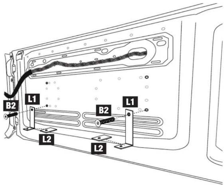
6
In the two lower threaded inserts, install L1 brackets using B2 allen bolts.
Apply the L2 Foam Bracket Pads to the brackets.
7
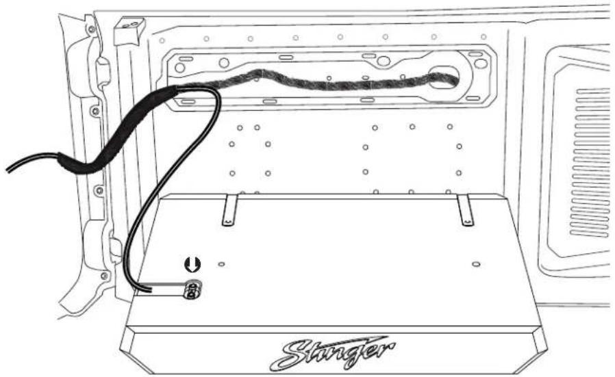
Run a suitable length of speaker wire into the swing gate following the factory wire harness.
Connect the speaker wire to the terminals. Positive (+) is Red and Negative (-) is Black. Route the speaker wire in the channel.
natural_image
Line drawing of a computer monitor with a black cable and labeled 'Stringer' on the base (no text or symbols beyond label)INSTALLATION
8
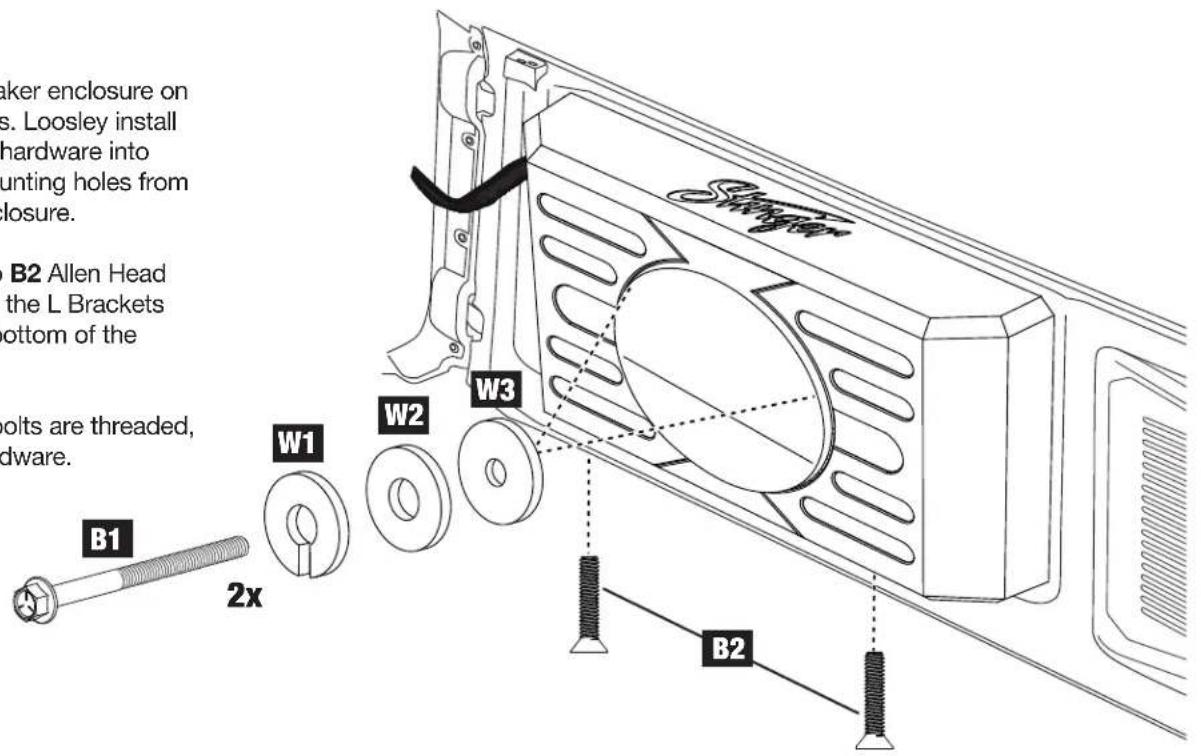
Align the speaker enclosure on the L Brackets. Loosley install the indicated hardware into the upper mounting holes from inside the enclosure.
Install the two B2 Allen Head Bolts through the L Brackets and into the bottom of the enclosure.
Once all the bolts are threaded, tighten all hardware.
9
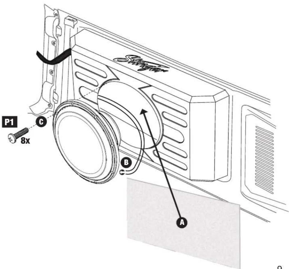
A. Place the sheet of poly-fill inside the enclosure along the back and side areas.
B. Connect the speaker leads inside the enclosure to either of the speaker terminals on the speaker. Positive (+) is Red and Negative (-) is Black.
NOTE: Ensure the pre-installed speaker terminal jumper wires stay connected when connecting the wires to the speaker terminal.
C. Align the speaker and install eight P1 screws securing the speaker.
SPECIFICATIONS
| Model Number TXFBB12 | |
| Speaker Model | SPC-12S2 |
| Subwoofer Size | 12" |
| Voice Coil | Single 2 ohm |
| DC Resistance (Re) | 2 ohm |
| Sensitivity 1W/M (SPL) | 87 dB |
| Frequency Response | 20Hz - 250Hz |
| RMS Power | Min 200w - Ideal 400w - Max 600w |
| Speaker Displacement | 0.06 cu ft / 1.82 Ltr |
| Speaker Weight | 12.5 lbs |
| Enclosure Specifications | |
| Internal Volume | 0.706 cu ft. / 19.99 Ltr |
| Enclosure Weight | 16.25 lbs |
| Height | 17in / 43.2cm |
| Width | 27.5in / 69.9cm |
| Depth | 4.6in / 11.7cm |
| Depth (with Speaker & Grill) | 5.8in / 14.7cm |
Height
17in / 43.2cm
Width
27.5in / 69.9cm
Depth
4.6in / 11.7cm

natural_image
Abstract black geometric logo resembling a stylized letter 'A' (no text or symbols)AAMP
ADVANCING VEHICLE TECHNOLOGY
Stinger is a Power Brand of AAMP Global
15500 Lightwave, Clearwater, Florida 33760
Phone: 888-228-5560
Technical Support
Phone: 727-592-5991
Email: support@stingerelectronics.com
Chat: stingerelectronics.com
Stinger and the Stinger logo are trademarks or registered trademarks of AAMP Global in the United States and other countries.
AAMP Global is not affiliated with FCA US LLC. Jeep® is a registered trademark of FCA US LLC. The terms OEM, Jeep, Wrangler, and Gladiator all terms are used strictly for identification purposes only. It is not implied that any part listed is a product of, or approved by, Fiat Chrysler Automobiles.
Brand : AudioControl
Model : TXFBB12
Category : Subwoofer