
Edge Encoder - Audio/video converter MATROX - Free user manual and instructions
Find the device manual for free Edge Encoder MATROX in PDF.


| Product type | Audio/video encoder, decoder, or simultaneous encode/decode appliance |
| Brand | Matrox |
| Model series | Monarch EDGE (E4, D4, S1) |
| Video compression | H.264/AVC up to High 4:2:2 Profile, 8-bit and 10-bit |
| Maximum video resolution | 3840x2160p at 60 fps (4K) |
| Video inputs (E4) | 3x 3G-SDI + 1x 12G-SDI (4K) |
| Video outputs (D4) | 3x 3G-SDI + 1x 12G-SDI (4K) |
| Video input/output (S1) | 1x 3G-SDI input, 1x 3G-SDI output |
| Audio | Balanced analog XLR (2 in, 2 out), embedded SDI audio (16 ch per input) |
| Network | 2x Gigabit Ethernet (LAN1, LAN2); optional SFP28 10/25 GbE cages |
| Genlock | Bi-level output (E4), bi/tri-level input (D4, S1) |
| Tally/GPIO | 15-pin D-SUB connector, configurable inputs/outputs |
| Control software | Monarch EDGE Control Hub (Windows) or web-based Command Center |
| Weight | 1.66 kg (3.66 lbs) |
| Power supply | External 12V DC adapter; input 100-240VAC, 50-60Hz; max 60W |
| Operating temperature | 0°C to 40°C |
| Storage temperature | -20°C to 60°C |
| Operating humidity | 20% to 80% non-condensing |
| Regulatory compliance | FCC Class A, CE Class A, RoHS |
| Maintenance | Clean exterior with dry cloth; firmware updates via updater tool; no user-serviceable parts inside |
| Optional accessories | SFP28 modules (third-party), break-out audio cable (MDG/AUD/CBL) |
Frequently Asked Questions - Edge Encoder MATROX
User questions about Edge Encoder MATROX
0 question about this device. Answer the ones you know or ask your own.
Ask a new question about this device
Download the instructions for your Audio/video converter in PDF format for free! Find your manual Edge Encoder - MATROX and take your electronic device back in hand. On this page are published all the documents necessary for the use of your device. Edge Encoder by MATROX.
USER MANUAL Edge Encoder MATROX
Matrox Monarch EDGE Series
Installation and User Guide
Part No.: V11470-301-0201(1)
Last Updated: April 4, 2022
Trademarks
All other nationally and internationally recognized trademarks and tradenames are hereby acknowledged.
See the Matrox Software License agreement
See the product's hardware warranty: http://www.matrox.com/video/en/support/warranty/
Copyright © 2022 Matrox Graphics Inc. • All rights reserved.
Disclaimer: Matrox Graphics Inc. reserves the right to make changes in specifications at any time and without notice. The information provided by this document is believed to be accurate and reliable. However, no responsibility is assumed by Matrox Graphics Inc. for its use; nor for any infringements of patents or other rights of third parties resulting from its use. No license is granted under any patents or patent rights of Matrox Graphics Inc. Unauthorized recording or use of broadcast television programming, video tape, or other copyrighted material may violate copyright laws. Matrox Graphics Inc. assumes no responsibility for the illegal duplication, use, or other acts that infringe on the rights of copyright owners.
Matrox Graphics Inc. 1055 St. Regis Blvd., Dorval, Quebec, Canada H9P 2T4 Tel: (514) 685-2630 Fax: (514) 685-2853 World Wide Web: www.matrox.com
Matrox Software License agreement
(Hereafter referred to as License)
THIS IS A LEGAL AGREEMENT BETWEEN THE LICENSEE AND MATROX GRAPHICS INC. ("MATROX") CONCERNING THE USAGE OF THE MATROX SOFTWARE. BY DOWNLOADING, INSTALLING, COPYING, ACCESSING, CLICKING ON AN "ACCEPT" BUTTON, OR OTHERWISE USING THE SOFTWARE, THE LICENSEE AGREES TO THE TERMS OF THIS LICENSE. IF YOU ARE ACCEPTING THESE TERMS ON BEHALF OF YOUR COMPANY, ORGANIZATION, EDUCATIONAL INSTITUTION, OR AGENCY, INSTRUMENTALITY, OR DEPARTMENT OF THE FEDERAL GOVERNMENT AS ITS AUTHORIZED LEGAL REPRESENTATIVE, YOU REPRESENT AND WARRANTY THAT YOU HAVE FULL AUTHORITY TO BIND LICENSEE TO THESE TERMS. IF YOU DO NOT AGREE TO THE TERMS OF THIS LICENSE, PLEASE RETURN YOUR MATROX PRODUCT. IF THE SOFTWARE WAS DOWNLOADED, DESTROY ALL COPIES OF THE SOFTWARE.
In this License "Software" refers to: any firmware, software, associated software components, media, printed materials, and "online" or electronic documentation related to Matrox products, and any related updates or upgrades thereto.
The Software is not sold, and instead is only licensed for use, strictly in accordance with this document. This License does not cover the sale of hardware, since it may not necessarily be sold as a package with the Software. This License sets forth the terms and conditions of the Software license only.
Any Software provided to Licensee is the copyrighted work of Matrox and/or third party software suppliers (if any). The present License does not give Licensee any intellectual property rights to the Software or its derivatives. The downloading and/or the use of any Software are subject to the following restrictions and limitations:
LICENSES
If you are an end user, the “End User License” shall apply to you. If you are an original equipment manufacturer (OEM), the “OEM License” shall apply to you.
END USER LICENSE
-
Licensee may install the Software on an unlimited number of computers owned or leased by Licensee in any location. The Software is subject to a restricted license therefore Licensee must use the Software on a single computer owned or leased by Licensee at a time, in conjunction with and for the purpose of, operating the Matrox hardware product. Use of the Software in conjunction with non-Matrox products is prohibited and not licensed hereunder. Licensee shall also have the right to make one copy of the Software in any computer-readable or printed form for back-up or archival purposes;
-
No right to recopy, publish, display, network, rent, loan, lend, assign, sell, distribute, license, sublicense, alter, modify, disassemble, de-compile, create derivative works or reverse engineer any Software in any manner whatsoever is hereby given, except as provided in this License. Violation may
result in severe civil and/or criminal penalties, as violators will be prosecuted to the maximum extent possible;
-
Licensee agrees to treat the Software as confidential information, and shall protect said information by using the same degree of care Licensee uses to protect Licensee's own confidential information, but no less than a reasonable degree of care, to prevent the unauthorized use, dissemination, disclosure or publication of such, or to use this Software to: (i) develop inventions directly derived from confidential information to seek patent protection; (ii) assist in the analysis of Licensee's patents and patent applications; or (iii) modify Licensee's existing patents or patent applications;
-
Licensee may only provide and disclose parts of the Software to third parties who have a need-to-know for the purpose of installation, service integration and/or support of said Software within Licensee's product. In such event, Licensee may only disclose the relevant and necessary parts of the Software to permit the third party to accomplish his work provided that all such disclosures shall be subject to the terms and conditions of this License;
-
Licensee may not grant any sublicense, lease or other right in the Software to others;
-
Notwithstanding any other provision in this License, if Licensee provides any ideas, suggestions or recommendations to Matrox regarding the Licensed Software and/or Licensee's product ("Feedback"), Matrox is free to use and incorporate such Feedback in Matrox's products, without payment of royalties or other consideration to Licensee;
-
Licensee shall not have the right to alter or remove any Matrox or third party copyright, trademark or patent notices in the Software.
OEM LICENSE
Licensee may reproduce and distribute the Software only as an integral part of or incorporated in Licensee's product or as a standalone Software maintenance update for existing end users of Licensee's products, excluding any other standalone products, subject to these conditions:
-
This Software is subject to a restrictive license therefore it is licensed for use only in conjunction with the Matrox hardware product. Use of the Software in conjunction with non-Matrox products is prohibited and not licensed hereunder;
-
No right to recopy, publish, display, sell, network, rent, loan, lend, distribute, license, sublicense, alter, modify, disassemble, decompile, create derivative works or reverse engineer any Software in any manner whatsoever is hereby given, except as provided in this License. Violation may result in severe civil and/or criminal penalties, as violators will be prosecuted to the maximum extent possible;
-
Licensee agrees to treat the Software as confidential information, and shall protect said information by using the same degree of care Licensee uses to protect Licensee's own confidential information, but no less than a reasonable degree of care, to prevent the unauthorized use, dissemination, disclosure or publication of such, or to use this Software to: (i) develop inventions directly derived from confidential information to seek patent protection; (ii) assist in the analysis of Licensee's patents and patent applications; or (iii) modify Licensee's existing patents or patent applications;
-
Licensee may only distribute the Software to Licensee's customers pursuant to a written license agreement. At a minimum such license shall safeguard Matrox's ownership rights to the Software and such agreement shall contain similar terms and obligations;
-
Licensee may only provide and disclose parts of the Software to third parties who have a need-to-know for the purpose of installation, service integration and/or support of said Software within Licensee's product. In such event, Licensee may only disclose the relevant and necessary parts of the Software to permit the third party to accomplish his work provided that all such disclosures shall be subject to the terms and conditions of this License;
- Notwithstanding any other provision in this License, if Licensee provides any ideas, suggestions or recommendations to Matrox regarding the Licensed Software and/or Licensee's product ("Feedback"), Matrox is free to use and incorporate such Feedback in Matrox's products, without payment of royalties or other consideration to Licensee;
- Licensee shall not have the right to alter or remove any Matrox or third party copyright, trademark or patent notices in the Software.
GENERAL LICENSE TERMS: (APPLICABLE TO BOTH END-USERS & OEMs)
There are inherent dangers in the use of any software available for downloading on the Internet and Matrox cautions Licensee to ensure that Licensee completely understands the potential risks before downloading any of the Software. Licensee is solely responsible for adequate protection and backup of the data and equipment used in connection with any of the Software, and Matrox will not be liable for any damages that may be suffered in connection with use of the Software.
Licensee hereby acknowledges and agrees that this License, and all its terms and conditions, automatically applies, without other notice, to future updates of the Software, firmware, BIOS, drivers and associated utilities.
In addition, certain third party intellectual property may be provided with or included in the Software. The third party license terms accompanying such Software, found at http://matrox.com/video/en/licenses/ and if applicable, in the license.txt file located in the root installation directory, will govern your use of such Software. Matrox does not warrant and is not liable for such third party intellectual property, or anything related thereto. Licensee acknowledges and agrees to comply with the terms of all applicable third party software licenses if any. Please be advised that the terms and conditions of third party license agreements may be updated from time to time. It is the responsibility of the Licensee to verify that the agreement listed is current and applicable. Please note that this list of third party licenses is not exhaustive and was determined according to Matrox's understanding and to the best of its knowledge.
PRE-RELEASE LICENSE EXCLUSION: If you are using a version of the licensed Software that is designated, without limitation, as an alpha, beta, engineering sample, preliminary or early access version of the Software, then; (a) the Software is deemed to be pre-release code (e.g. alpha or beta, engineering sample, preliminary, early access, etc.), which may not be fully functional and which Matrox may substantially modify in development of a commercial version, and for which Matrox makes no assurances that it will ever develop or make generally available in a commercial version, and (b) Licensee shall have the right to use the Software only for the duration of the pre-release term or until the commercial release, if any, of the Software, whichever is shorter. For clarity, a remedy to any bug, defect, error or fault in any pre-release version of the Software will absolutely require upgrading to a new version of the Software. Matrox reserves the right to change any content of this new version of the Software at its sole discretion.
COPYRIGHT
All title, including but not limited to copyrights, in and to the Software and any copies thereof are owned by Matrox or its suppliers. All title and intellectual property rights in and to the content which may be accessed through use of the Software is the property of the respective content owner and may be protected by applicable copyright or other intellectual property laws and treaties. This License grants you no rights to use such content. All rights not expressly granted are reserved by Matrox.
DISCLAIMER OF WARRANTIES
LICENSEE EXPRESSLY ACKNOWLEDGES AND AGREES THAT USE OF THE SOFTWARE IS AT LICENSEE'S SOLE RISK. THE SOFTWARE IS PROVIDED "AS IS" AND WITHOUT WARRANTY OF ANY KIND AND MATROX EXPRESSLY DISCLAIMS ALL WARRANTIES, EXPRESS AND IMPLIED, INCLUDING, BUT NOT LIMITED TO, THE IMPLIED WARRANTIES OF MERCHANTABILITY, FITNESS FOR A PARTICULAR PURPOSE AND NON-INFRINGEMENT OF ITS SOFTWARE AND ANY THIRD PARTY INTELLECTUAL PROPERTY. MATROX DOES NOT WARRANT THAT THE CONTENTS OF THE SOFTWARE WILL MEET LICENSEE'S REQUIREMENTS, OR THAT THE OPERATION OF THE SOFTWARE WILL BE UNINTERRUPTED OR ERROR-FREE, OR THAT DEFECTS IN THE SOFTWARE WILL BE CORRECTED. THE ENTIRE RISK ASSOCIATED WITH THE USE OF THE SOFTWARE IS ASSUMED BY LICENSEE. FURTHERMORE, MATROX DOES NOT WARRANT OR MAKE ANY REPRESENTATIONS REGARDING THE USE OR THE RESULTS OF THE USE, OF THE SOFTWARE OR ANY THIRD PARTY INTELLECTUAL PROPERTY IN TERMS OF ITS CORRECTNESS, ACCURACY, RELIABILITY, CURRENTNESS, OR OTHERWISE. SHOULD THE CONTENTS OF THE SOFTWARE PROVE DEFECTIVE, LICENSEE ASSUMES THE ENTIRE COST OF ALL NECESSARY SERVICING, REPAIR OR CORRECTION. SOME JURISDICTIONS DO NOT ALLOW THE EXCLUSION OF IMPLIED WARRANTIES, SO THE ABOVE EXCLUSION MAY NOT APPLY TO LICENSEE. LICENSEE ACKNOWLEDGES AND AGREES THAT LICENSEE IS SOLELY RESPONSIBLE FOR DETERMINING WHETHER ANY THIRD PARTY PATENT OR COPYRIGHT LICENSES, INCLUDING BUT NOT LIMITED TO VARIOUS AUDIO AND VISUAL STANDARDS, ARE NECESSARY TO USE, IMPLEMENT OR DISTRIBUTE THIS PRODUCT, WHICH INCLUDES ANY OR ALL SOFTWARE OR HARDWARE. LICENSEE IS RESPONSIBLE TO ADVISE LICENSEE'S CUSTOMERS OF THE LIMITATIONS PROVIDED HEREIN.
LIMITATION OF LIABILITY
UNDER NO CIRCUMSTANCES SHALL MATROX, ITS SISTER COMPANIES, ITS SUBSIDIARIES BE LIABLE FOR ANY DIRECT, INDIRECT, PUNITIVE, INCIDENTAL, SPECIAL, OR CONSEQUENTIAL DAMAGES THAT RESULT FROM THE USE OF, OR INABILITY TO USE, THE SOFTWARE. THIS LIMITATION APPLIES WHETHER THE ALLEGED LIABILITY IS BASED ON CONTRACT, TORT, NEGLIGENCE, STRICT LIABILITY, OR ANY OTHER BASIS, EVEN IF MATROX HAS BEEN ADVISED OF THE POSSIBILITY OF SUCH DAMAGE. BECAUSE SOME JURISDICTIONS DO NOT ALLOW THE EXCLUSION OR LIMITATION OF INCIDENTAL OR CONSEQUENTIAL DAMAGES, MATROX'S LIABILITY IN SUCH JURISDICTIONS SHALL BE LIMITED TO THE MINIMUM REQUIRED BY LAW.
UNAUTHORIZED USE. THIS SOFTWARE IS NOT DESIGNED, INTENDED, AUTHORIZED OR WARRANTED TO BE SUITABLE FOR USE OR RESALE IN ANY TYPE OF SYSTEM OR OTHER APPLICATIONS RELATED TO, HAZARDOUS OR POTENTIALLY HAZARDOUS ENVIRONMENTS OR APPLICATIONS REQUIRING HIGH-AVAILABILITY OR FAIL-SAFE PERFORMANCE, WHERE PERSONAL INJURY OR DEATH MAY OCCUR, SUCH AS MEDICAL SYSTEMS, LIFE SUSTAINING, LIFE SAVING SYSTEMS, OPERATION OF NUCLEAR FACILITIES, AIRCRAFT NAVIGATION OR COMMUNICATION SYSTEMS, AIR TRAFFIC CONTROL, PUBLIC WORKS, WEAPONS SYSTEMS, OR ANY OTHER APPLICATION IN WHICH THE FAILURE OF A PRODUCT COULD LEAD TO PROP-
ERTY DAMAGE, ENVIRONMENTAL DAMAGE, OR PERSONAL INJURY. LICENSEE WILL NOT USE, OR PERMIT TO BE USED, THE PRODUCTS FOR SUCH HIGH-AVAILABILITY, FAIL-SAFE OR CRITICAL APPLICATIONS AND FURTHER, LICENSEE AGREES TO INDEMNIFY, DEFEND AND HOLD HARMLESS MATROX AND ITS MANAGERS, DIRECTORS, OFFICERS, EMPLOYEES, AGENTS, AFFILIATES, SUCCESSORS, ASSIGNS AND ITS THIRD PARTY SUPPLIERS FROM AND AGAINST ANY ACTION, SUIT, PROCEEDING, COST, EXPENSE, DAMAGES, AND LIABILITY (INCLUDING, BUT NOT LIMITED TO, REASONABLE ATTORNEYS' FEES) ARISING OUT OF, OR RELATED TO, THE BREACH OF LICENSEE'S OBLIGATIONS RELATED HERETO, EVEN IF SUCH CLAIM ALLEGES THAT MATROX WAS NEGLIGENT REGARDING THE DESIGN OR MANUFACTURE OF THE SOFTWARE.
DISCLAIMER OF WARRANTIES AND LIMITATION OF LIABILITIES FOR THIRD PARTY SOFTWARE INCLUDED WITH OR IN THE SOFTWARE. ALL THIRD PARTY SOFTWARE INCLUDED WITH THE SOFTWARE IS PROVIDED ON AN "AS IS" BASIS. MATROX AND ITS THIRD PARTY SUPPLIERS MAKE NO WARRANTY TO LICENSEE, WHETHER EXPRESS OR IMPLIED, INCLUDING WITHOUT LIMITATION THE IMPLIED WARRANTIES OF MERCHANTABILITY AND FITNESS FOR A PARTICULAR PURPOSE AND NON-INFRINGEMENT, REGARDING ANY THIRD PARTY SOFTWARE, OR ITS USE AND OPERATION ALONE OR IN COMBINATION WITH LICENSEE PRODUCTS. NEITHER LICENSEE, NOR ITS EMPLOYEES, AGENTS, OR DISTRIBUTORS HAVE ANY RIGHT TO MAKE ANY OTHER REPRESENTATION, WARRANTY OR PROMISE WITH RESPECT TO ALL THIRD PARTY SOFTWARE INCLUDED WITH THE SOFTWARE. MATROX HAS NO OBLIGATION TO INDEMNIFY, DEFEND OR HOLD LICENSEE HARMLESS FROM AND AGAINST ANY CLAIM THAT ANY THIRD PARTY SOFTWARE INFRINGES ANY THIRD PARTY PATENT, COPYRIGHT, TRADEMARK OR OTHER INTELLECTUAL PROPERTY RIGHT. LICENSEE WILL PROMPTLY NOTIFY MATROX IN WRITING OF ANY SUCH CLAIM.
MATROX HAS NO OBLIGATION TO INDEMNIFY, DEFEND OR HOLD LICENSEE HARMLESS FROM AND AGAINST ANY CLAIMS OF INFRINGEMENT OF INTELLECTUAL PROPERTY THAT READS UPON OR IS INFRINGED BY A GENERALLY RECOGNIZED AUDIO, VIDEO, TECHNOLOGY OR PATENT STANDARD OR RECOMMENDATIONS, INCLUDING WITHOUT LIMITATION AVC/H.264, IEEE 1394, JPEG, JPEG2000 AND MPEG-4.
IN ANY EVENT, MATROX'S TOTAL CUMULATIVE LIABILITY TO LICENSEE FOR ANY AND ALL CAUSE OF ACTION SHALL BE LIMITED TO THE AGGREGATE OF ALL AMOUNTS PAID BY LICENSEE TO MATROX, DURING THE TWELVE (12) MONTH PERIOD PRIOR TO OBTAINING A FINAL, NONAPPEALABLE JUDGMENT OR \$50,000.00 USD, WHICHEVER IS LOWER. THE FOREGOING LIMITATIONS WILL APPLY EVEN IF THE ABOVE STATED REMEDY FAILS OF ITS ESSENTIAL PURPOSE.
TERMINATION
This License will automatically terminate if Licensee fails to comply with any of the terms and conditions hereof. In such event, Licensee must destroy all copies of the Software and all of its component parts. Matrox reserves the right to terminate this License without prejudice to any additional recourses Matrox may have against Licensee if Licensee violates any of the terms and conditions of this License.
Matrox will not, by reason of the termination of this License, be liable for compensation, reimbursement or damages on account of the loss of prospective profits on anticipated sales, or on account of expenditures, investments, leases, or commitments in connection with the Licensee's business or goodwill or otherwise. If Licensee commences or participates in any legal proceeding against Matrox then Matrox may, in its sole dis-
cretion, suspend or terminate all license grants and any other rights provided under this License during the pendency of such legal proceedings.
MISCELLANEOUS
If any provision of this License is inconsistent with, or cannot be fully enforced under, the law, such provision will be construed as limited to the extent necessary to be consistent with and fully enforceable under the law. This License is the final, complete and exclusive agreement between the parties relating to the subject matter hereof, and supersedes all prior or contemporaneous understandings and agreements relating to such subject matter, whether oral or written. This License may only be modified in writing signed by an authorized officer of Matrox. Licensee agrees that it will not ship, transfer or export the Software into any country, or use the Software in any manner, prohibited by the United States Bureau of Industry and Security and shall fully comply with all United States and Canadian relevant export laws, restrictions or regulations and any other applicable export and import laws.
Controlling Law. The validity, performance and construction hereof shall be governed by and interpreted in accordance with the laws of the Province of Quebec. Both parties hereby irrevocably submit to the exclusive jurisdiction of the Courts of the district of Montreal, Province of Quebec, Canada with regard to any dispute arising out of or in connection with this License.
Additional information may be available on the Matrox website. If used, this site may contain other proprietary notices and copyright information, the terms of which must also be observed and followed.
The failure of Matrox to enforce at any time any of the provisions of this License, or the failure to require at any time performance by the Licensee of any of the provisions of this License, shall in no way be construed to be a present or future waiver of such provisions, nor in any way affect the right of Matrox to enforce each and every such provision thereafter.
Any and all articles and/or sections which by their nature are required to survive termination of this License shall survive.
ANY INTERPRETATION OF THE CONTENTS, RIGHTS AND OBLIGATIONS OF THE CONTENTS OF THIS NOTICE AND/OR MATROX WEB SITE SHALL BE INTERPRETED IN ACCORDANCE WITH THE LAWS OF QUEBEC.
Matrox reserves the right to change Software specification without notice. All intellectual property, including without limitation, trademarks and copyrights are the property of their respective owners and any unauthorized use thereof is strictly prohibited.
Copyright © 2017 Matrox. All rights reserved. Matrox is a trademark of Matrox Electronic Systems Ltd.
SLA08282017
Table of contents
Trademarks
Matrox Software License agreement
Chapter 1: Introduction
About the Matrox Monarch EDGE Series.... 1
Matrox Monarch EDGE E4 and Monarch EDGE D4....1
Matrox Monarch EDGE S1....2
Matrox Monarch EDGE Control Hub 2
Matrox Monarch EDGE Command Center.... 2
Matrox Monarch EDGE RESTful API 2
System requirements.... 3
Installation and configuration overview.... 3
Chapter 2: Hardware connections
Matrox Monarch EDGE front connections 6
Matrox Monarch EDGE E4 and D4 rear connections....7
Matrox Monarch EDGE S1 rear connections.... 9
Matrox Monarch EDGE front panel.... 11
Description of LEDs 12
Chapter 3: Monarch EDGE firmware update and Control Hub installation
If you are using Monarch EDGE Command Center.... 13
Update and installation prerequisites.... 13
Updating the Monarch EDGE firmware 14
Installing Monarch EDGE Control Hub 16
Uninstalling or repairing Monarch EDGE Control Hub.... 16
Chapter 4: Network management
About Matrox Monarch EDGE device discovery.... 17
Discovering devices automatically 17
Discovering devices manually.... 17
Assigning a static IP address to a Monarch EDGE 19
Monarch EDGE firewall requirements 19
Chapter 5: User and device management
About User and Device Management.... 21
Starting up Matrox Monarch EDGE Control Hub 22
Environment administrator accounts 22
About environment administrators.... 23
Creating an environment administrator account.... 23
User accounts.... 24
About user accounts.... 24
Creating a user account 25
Managing users and device permissions.... 26
Transferring control to a different environment administrator.... 26
Changing the environment password.... 27
Changing user accounts.... 29
Managing user accounts and permissions.... 30
Chapter 6: Monarch EDGE Control Hub configuration
Monitoring Monarch EDGE devices.... 32
About the Monarch EDGE Control Hub user interface 32
Using the contextual menu for encoder and decoder settings 33
Configuring Encoder Processing settings.... 35
Inputs/Outputs 35
Processing.... 36
Encodings.... 38
Streams 42
Recordings 46
Configuring Decoder Processing settings.... 48
Input streams.... 48
SDI Outputs....50
Configuring Network settings.... 51
Configuring Date and Time settings 52
Configuring Genlock settings.... 53
Configuring DP Output settings 54
Configuring Tally settings 54
About Test Mode and Live Mode 54
Testing your Tally and GPI connections.... 55
Using your Tally and GPI connections 55
Configuring Talkback settings.... 56
Managing Logs 57
Managing configurations.... 57
Grouping Monarch EDGE devices.... 57
Chapter 7: Monarch EDGE Command Center configuration
About Monarch EDGE Command Center.... 60
Logging in to Monarch EDGE Command Center.... 60
About the Monarch EDGE Command Center user interface 61
Using the contextual menu for encoder and decoder settings 62
Configuring Encode settings.... 65
Inputs/Output 65
Input processes....66
Encodings.... 69
Streams 73
Recordings 77
Configuring Decode settings.... 79
Input streams....79
Genlock 80
Audio Output 81
Configuring Network settings.... 82
Configuring Tally settings 83
About Test Mode and Live Mode 83
Testing your Tally and GPI connections.... 83
Using your Tally and GPI connections 84
Configuring Talkback settings.... 85
Configuring Genlock settings.... 86
Configuring DP Output settings 86
Configuring Date and Time settings 87
Managing configurations.... 88
Managing Logs 88
Managing SyncGroups 89
Configuring User management settings 89
Appendix A: Technical specifications
General 91
Connections....92
MDG4/E10/I, MDG4/E8/I, and MDG4/D/I devices....92
MDG2/ED10/I 93
Compression....94
Dimensions....96
Environmental specifications 97
Appendix B: Tally and GPIO circuits
Monarch EDGE E4 and S1....98
Electrical characteristics.... 98
Connector wiring pinout....99
Monarch EDGE D4....100
Electrical characteristics.... 100
Connector wiring pinout.... 101
Output wiring.... 102
Appendix C: Analog audio cable specification
XLR audio cable connector pinouts....104
CHAPTER 1
Introduction
This chapter includes the following topics:
- About the Matrox Monarch EDGE Series
- System requirements
• Installation and configuration overview
About the Matrox Monarch EDGE Series
The Matrox Monarch EDGE series of H.264-based encoding and decoding appliances are designed for 4K/Multi-HD Webcasting and Remote Production and contribution workflows. This user guide includes information for the Monarch EDGE E4, Monarch EDGE D4, and Monarch EDGE S1 devices.
For more information on the Monarch EDGE Series of products, go to our website at: https://www.matrox.com/en/video/products/encoders-decoders/monarch-edge-series/monarch-edge-remote-production
Matrox Monarch EDGE E4 and Monarch EDGE D4
Coupled with the powerful Monarch EDGE D4 decoder, the Monarch EDGE E4 encoding device offers exceptional quality at the lowest latency while securely transporting your video feeds from the event to the centralized production facility. This compact, robust, and low-power remote production (REMI) encoder and decoder pair has made producing live, multi-camera events more affordable than ever by keeping talent in-house.
Programs destined for web or over-the-top (OTT) delivery to the cloud can select the Monarch EDGE E4 4:2:0 8-bit encoder, while the 4:2:2 10-bit capable Monarch EDGE E4 is ideal for demanding, broadcast-quality productions.
Matrox Monarch EDGE S1
Affordably enhance remote production (REMI) workflows with Monarch EDGE S1. A simultaneous encode/decode appliance, Monarch EDGE S1 allows users to provide low latency return feeds to multi-camera production crews in the field. Monarch EDGE S1 offers one 3G-SDI input, allowing return feeds coming from studio to be encoded for secure transport over private or public internet connections. At remote sites, Monarch EDGE S1 can decode one HD feed and output via a genlockable 3G-SDI connection for distribution of the program feed. As both encode and decode operations can occur simultaneously, a single camera contributor in the field can use this device to both send a high-quality feed to studio and receive the program feed being produced by the studio.
Matrox Monarch EDGE Control Hub
The Matrox Monarch EDGE Control Hub software is the primary configuration application for the majority of users. It enables you to remotely control, manage, and configure your Monarch EDGE device from a Windows computer connected to your network.
Matrox Monarch EDGE Control Hub is packaged with the Monarch EDGE firmware and can be downloaded from the support section of our website.
Matrox Monarch EDGE Command Center
The Matrox Monarch EDGE Command Center provides almost all of the same configuration options as Monarch EDGE Control Hub, but is optimized for a web-based workflow. Instead of installing software on your computer, you use a web browser to securely access and configure the Monarch EDGE device.
Matrox Monarch EDGE RESTful API
The Matrox RESTful API provides a set of JSON-based commands that allow you to control, manage, and configure your Monarch EDGE E4 the same way you would with the Matrox Monarch EDGE Control Hub application.
The API is typically used by OEMs to create their own application for the Monarch EDGE E4. Documentation for the API is provided as comments in the JSON code which is then extracted to an HTML file for easy reading. This offers developers an efficient method of understanding the basic commands of the Monarch EDGE E4.
The API should be considered a supplement to this user guide, as the API does not explain the overall functionality of the Monarch EDGE E4.
For more information on the RESTful API, contact your Matrox representative.
System requirements
The system requirements for all Monarch EDGE devices are as follows:
- To install Matrox Monarch EDGE Control Hub, you need a computer running Microsoft Windows 10. Other Windows operating systems may work but have not been fully validated through internal testing. Before trying another operating system, contact Matrox support.
- To access Matrox Monarch EDGE Command Center, we recommend using Google Chrome for an optimal user experience. Other web browsers (e.g. Mozilla Firefox) may work but have not been fully validated through internal testing.
- It is recommended to use a DHCP-enabled (Dynamic Host Configuration Protocol) network with SSDP Discovery service, network discovery, and file sharing options enabled. If a DHCP network is not available, the Monarch EDGE device will boot with a self-assigned link-local IP address between 169.254.0.0 and 169.254.255.255 which will be displayed on the front LCD screen upon boot up. For more information on link-local addressing, contact your network administrator.
For full hardware and other technical specifications, such as the supported video formats, see "Technical specifications" on page 53.
Installation and configuration overview
This section provides a general roadmap for getting started with Monarch EDGE devices. For more detailed information, links are provided to refer you to the relevant topics described in other parts of this manual.
Step 1. Read the Release Notes Before getting started, it is always recommended to read the Matrox Monarch EDGE Release Notes available on the Matrox website where you download the installation package. The Release Notes contain the latest information about the release, including new features and known issues.
Step 2. Connect your Hardware Start by connecting and powering up your Mon-arch EDGE device(s). A DHCP network is recommended for device discovery. The setup sheet included with your product describes the basic connections. More info: see "Hardware connections" on page 5.
Step 3. Update Monarch EDGE firmware When you first connect and power up your Monarch EDGE device, you should check to see which firmware you have, and update it if it is not the most current version. The setup sheet included with your product describes the firmware update process. More info: see "Monarch EDGE firmware update and Control Hub installation" on page 13.
Step 4. Start configuring Monarch EDGE You can configure Monarch EDGE using the Monarch EDGE Control Hub installable software, or by using the web-based Monarch EDGE Command Center (available on devices with firmware version 2.01 and later).
More info: If you are using Monarch EDGE Command Center, open your web browser (Google Chrome is recommended) and go to your Monarch EDGE's IP address. For a secure connection, use the "https" prefix (e.g. https://192.168.123.456). After you log in to Command Center, continue to Step 8.
Step 5. Install Monarch EDGE Control Hub This is the installable application you use to configure and control your Monarch EDGE devices. The version of Monarch EDGE Control Hub you install must match the firmware version of the Monarch EDGE device(s). The setup sheet included with your product describes the installation process.
More info: see "Monarch EDGE firmware update and Control Hub installation" on page 13.
Step 6. Discover your Monarch EDGE devices With Monarch EDGE Control Hub installed, you need to discover the Monarch EDGE devices available on the network. You can search for specific devices or for a range of devices.
More info: see "Network management" on page 17.
Step 7. Create an environment administrator To configure your Monarch EDGE devices, you must first create an environment administrator account. Monarch EDGE devices are grouped into different environments.
More info: see "User and device management" on page 21.
Step 8. Create user accounts Whether you use Control Hub or Command Center to configure your Monarch EDGE devices, you will need to create user accounts with specific permissions to use devices.
More info: see "User and device management" on page 21.
Step 9. Configure Monarch EDGE devices You can now use Monarch EDGE Control Hub or Monarch EDGE Command Center to configure your devices as needed.
More info: see "Monarch EDGE Control Hub configuration" on page 31 or "Monarch EDGE Command Center configuration" on page 59.
Result of this task: You are ready to use your Matrox Monarch EDGE device(s).
CHAPTER 2
Hardware connections
This chapter includes the following topics:
- Matrox Monarch EDGE front connections
- Matrox Monarch EDGE E4 and D4 rear connections
• Matrox Monarch EDGE S1 rear connections
• Matrox Monarch EDGE front panel
• Description of LEDs
Matrox Monarch EDGE front connections
The Matrox Monarch EDGE E4 8-bit encoder is shown for illustration purposes only. The information below applies to all Monarch EDGE devices.
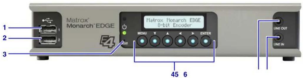
| Connector Description | ||
| 1 | USB port 1 For internal use only. | |
| 2 | USB port 2 For internal use only. | |
| 3 | RESET | Reboots the Monarch EDGE with a short press, or resets to factory default settings with a long press of about five seconds (until green light flashes).A factory reset will also remove any user accounts or environment administrator accounts associated to this Monarch EDGE. For more information, see "Environment administrator accounts" on page 22.NOTE Pressing the Reset button too long will cause the Monarch EDGE to enter maintenance mode (amber light). This mode is used for internal purposes only. If this occurs, reboot the EDGE and try the factory reset again. |
| 4 | Front Panel Buttons | Monarch EDGE front panel buttons are used to cycle through the information on the LCD display. For more information on how the front panel works, see "Matrox Monarch EDGE front panel" on page 11. |
| 5 | LINE OUT Connect your headphones to this connector. | |
| 6 | LINE IN Not currently supported. | |
Matrox Monarch EDGE E4 and D4 rear connections
The information below applies to Monarch EDGE E4 and D4 devices.
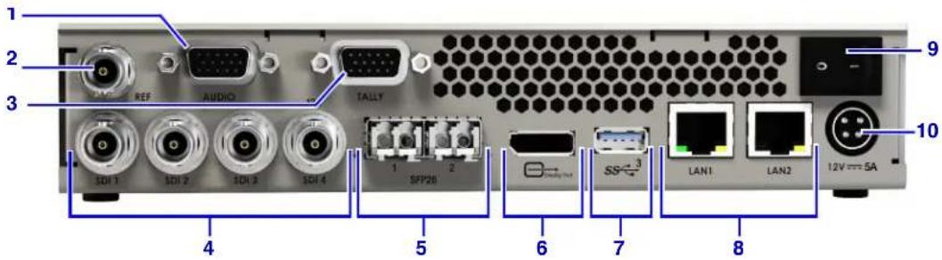
| Connector Description | ||
| 1 | A U | Analog XLR audio with two balanced analog audio inputs and outputs. On the Monarch EDGE E4, these can be used for program audio or for Talkback functionality (when used for Talkback, analog audio is not available). On the Monarch EDGE D4, the analog audio is only used for Talkback.NOTE A separate audio cable is available for purchase. |
| 2 | R | For Monarch EDGE E4, this is a bi-level genlock output. For Monarch EDGE D4, this is a bi- or tri-level genlock input. |
| 3 TALLY | Connect to a production switcher for the transfer of tally signals between in-studio switchers and on-site cameras.Although the physical connector is the same on Monarch EDGE E4 and D4 devices, the Monarch EDGE E4 uses the connector's pins as four GPI inputs and eight Tally outputs, while the Monarch EDGE D4 uses them as eight Tally inputs and four GPI outputs. | |
| 4 | S D ^1 | SDI connectors function as inputs on the Monarch EDGE E4 and outputs on the Monarch EDGE D4.Connectors 1 to 3 are 3G SDI per SMPTE ST 425 (Level A mapping only). SDI connector 4 is a 12G SDI per SMPTE ST 2082 and supports 4K when connectors 1 to 3 are not being used |
| 5 SFP28 1 and 2 | SFP 1 and 2 are MSA-compatible SFP28 cages supporting 10 and 25 GbE modules. To be supported in a future release for SMPTE ST 2110 signals.NOTE The SFP28 connectors are shown for illustration purposes only. They are not included with your Monarch EDGE, and must be purchased separately from a third-party. | |
| 6 | D i 2s | Connect a DisplayPort monitor to this connector to use as a preview monitor for your video sources. If your monitor does not have a DisplayPort connector, you can use an HDMI or DVI-D adapter. Use only HD monitors (1920 × 1200 maximum) for DisplayPort preview. Higher resolution monitors will negatively impact processing performance. |
| 7 USB 3.0 port | For Monarch EDGE E4, this port can be used for saving recorded content to a compatible USB device. NTFS and FAT32 file systems are supported, however, please note that FAT32 has a maximum file limitation size of 4 GB. | |
| 8 | LAN1 | Connect a network cable to this connector. This connector is used for controlling and streaming. This connector is also the one you must use for the initial boot up of Monarch EDGE. |
| LAN2 | If you're using multiple subnets, or if you want to separate your control network from your media network, connect a network cable to this connector. This connector is used for secondary streaming. | |
| 9 Power Turn your Monarch EDGE on or off. | ||
| 10 12V DC power | Connect the included 12V DC power supply to this connector. While the 12V DC power supply is connected to the device and electrical socket, the power LED is active (not black). | |
- If your SDI input source changes from interlaced to progressive while streaming, the input will become disabled, and you will need to re-enable the input to continue streaming.
- The preview feature will affect the Monarch EDGE encoding and decoding performance. If you use preview while the Monarch EDGE is streaming, you may experience performance-related issues.
Matrox Monarch EDGE S1 rear connections
The information below applies to Monarch EDGE S1.
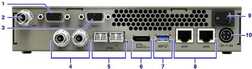
| Connector Description | ||
| 1 | A U | Analog XLR audio with two balanced analog audio inputs and outputs. When encoding, these can be used for program audio or for Talkback functionality (when used for Talkback, analog audio is not available). When decoding, the analog audio is only used for Talkback.NOTE A separate audio cable is available for purchase. |
| 2 REF Bi- or tri-level genlock input. | ||
| 3 TALLY | Connect to a production switcher for the transfer of tally signals between in-studio switchers and on-site cameras.The Monarch EDGE S1 can be paired with another Monarch EDGE S1, a Monarch EDGE E4, or a Monarch EDGE D4. When paired with another S1 or E4 device, four GPI inputs and outputs are usable on each device (tally connections 5, 6, 7, and 8 are not available). When paired with a D4 device, the Tally behavior works similar to the typical Monarch E4 to D4 behavior. | |
| 4 | SDI 1 and SDI 2^1 | SDI 1 functions as the input. SDI 2 functions as the output. Both connections are 3G SDI per SMPTE ST 425 (Level A mapping only) and support 8- and 10-bit simultaneous encoding and decoding capability. |
| 5 SFP28 1 and 2 | SFP 1 and 2 are MSA-compatible SFP28 cages supporting 10 and 25 GbE modules. To be supported in a future release for SMPTE ST 2110 signals.NOTE The SFP28 connectors are shown for illustration purposes only. They are not included with your Monarch EDGE, and must be purchased separately from a third-party. | |
| 6 | D i 2s | Connect a DisplayPort monitor to this connector to use as a preview monitor for your video sources. If your monitor does not have a DisplayPort connector, you can use an HDMI or DVI-D adapter. Use only HD monitors (1920 × 1200 maximum) for DisplayPort preview. Higher resolution monitors will negatively impact processing performance. |
| 7 USB 3.0 port | For encoding, this port can be used for saving recorded content to a compatible USB device. NTFS and FAT32 file systems are supported, however, please note that FAT32 has a maximum file limitation size of 4 GB. | |
| 8 | LAN1 | Connect a network cable to this connector. This connector is used for controlling and streaming. This connector is also the one you must use for the initial boot up of Monarch EDGE. |
| LAN2 | If you're using multiple subnets, or if you want to separate your control network from your media network, connect a network cable to this connector. This connector is used for secondary streaming. | |
| 9 Power Turn your Monarch EDGE on or off. | ||
| 10 12V DC power | Connect the included 12V DC power supply to this connector. While the 12V DC power supply is connected to the device and electrical socket, the power LED is active (not black). | |
- If your SDI input source changes from interlaced to progressive while streaming, the input will become disabled, and you will need to re-enable the input to continue streaming.
- The preview feature will affect the Monarch EDGE encoding and decoding performance. If you use preview while the Monarch EDGE is streaming, you may experience performance-related issues.
Matrox Monarch EDGE front panel
This section describes how to use the Matrox Monarch EDGE front panel buttons. Although the Monarch EDGE E4 8-bit appliance is shown, this information applies to all versions of Monarch EDGE.
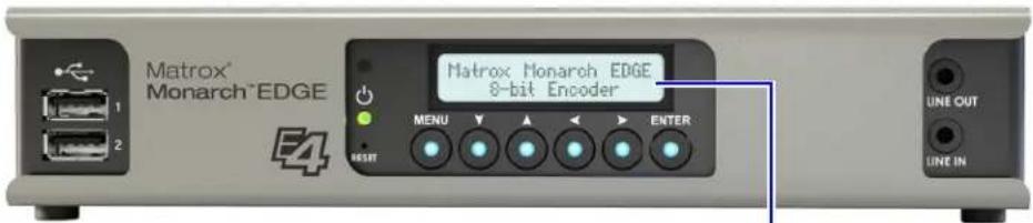
When not being used (idle mode), the Monarch EDGE LCD screen will not display information. Otherwise, it will scroll through the device's status (e.g. IP address, MAC address, etc).
| Button Function | |
| MENU | Access the Monarch EDGE menu from idle mode. Once in the menu, this button acts as a “back” button to return to a previous option or to cancel an option. |
| Arrow buttons | Navigate through submenus and options. |
| ENTER | Enter a submenu or make a selection. |
The front panel menu gives you access to the following settings:
| Menu option | Submenu option | Settings |
| Device info N/A | Manually scroll through the same status information that is displayed in idle mode. | |
| Device config | Network settings | Set the Lan1 or Lan2 to DHCP or Static IP modes (using the arrow buttons). When in Static IP mode, you can also specify the desired IP address. |
| Audio settings | Select the audio source for the Line Out connector. | |
| Maintenance | Used to reboot or factory reset the Monarch EDGE, and clear or save the logs to a USB key.NOTE The save to USB option is only available when a USB key is connected to the Monarch EDGE. |
Description of LEDs
The LED on your Monarch EDGE device provides information to help you troubleshoot your product. The following describes the LEDs on your device.
| Color What it means | |
| No LED (black) Device isn’t powered. | |
| Green (solid) Device is active. | |
| Green (slow blink) Device is rebooting. | |
| Green (fast blink) Configuration reset in process. | |
| Amber (solid) | Device is in maintenance mode. ^1 |
| Amber (slow blink) Device is restarting and is in maintenance mode. | |
| Amber (fast blink) Device is updating the firmware. | |
| Red (solid) | Device has detected a fatal error. Try rebooting your device. If, after restarting your device, the LED is still red, contact Matrox support. |
- To enter maintenance mode, press the RESET pin on the Monarch EDGE front panel for more than 10 seconds. Do not use this mode unless asked by Matrox technical support and under their supervision.
CHAPTER 3
Monarch EDGE firmware update and Control Hub installation
This chapter includes the following topics:
- If you are using Monarch EDGE Command Center
- Update and installation prerequisites
- Updating the Monarch EDGE firmware
• Installing Monarch EDGE Control Hub - Uninstalling or repairing Monarch EDGE Control Hub
If you are using Monarch EDGE Command Center
Monarch EDGE Command Center is a web-based configuration tool and does not need to be installed. This means that you can ignore the topics and statements in this chapter regarding Control Hub installation.
However, you can only use Monarch EDGE Command Center on EDGE devices running firmware version 2.01 or later, so you may need to update your device firmware as described in the sections "Update and installation prerequisites" on page 13 and "Updating the Monarch EDGE firmware" on page 14.
Update and installation prerequisites
Before you update your Monarch EDGE firmware and install Monarch EDGE Control Hub, please read and comply with the following:
- The versions of Monarch EDGE firmware and Monarch EDGE Control Hub must match to ensure proper functionality and compatibility between devices and software.
- You may need administrator rights to install or uninstall Monarch EDGE Control Hub. For more information, see your Windows documentation or contact your system administrator.
- When you power on the Monarch EDGE, the LAN1 connector on the device must be connected to a network ("LAN", 100/1000 Base-T) for the Monarch EDGE to be seen by the firmware updater. Monarch EDGE will not boot unless the LAN1 is connected to a network or LAN.
- It is recommended that you connect to a DHCP-enabled network, and that your server maintains the IP address of a device when it reappears on the network after a reboot. However, if a DHCP network is not available, the Monarch EDGE will boot with a randomly-assigned link-local address between 169.254.0.0 and 169.254.255.255. For more information on link-local IP addressing, contact your network administrator.
- The latest version of Microsoft .NET Framework is required to run the Monarch EDGE firmware updater and Monarch EDGE Control Hub, as well as to identify Monarch EDGE devices on a network.
- Stop all processing sessions on your Monarch EDGE devices.
- Close Monarch EDGE Control Hub if it is running.
- Make sure you have at least 1 GB of free disk space available.
- Use only one instance of the firmware updater on your network at a time.
- If your system doesn't have access to a DNS server, use a fixed IP address (such as local host - 127.0.0.1) as its DNS server. Otherwise, the firmware update process may take a long time to complete.
Updating the Monarch EDGE firmware
The Matrox Monarch EDGE firmware updater allows you to remotely update the firmware on multiple devices on your network at once.
To update the Monarch EDGE devices, follow the steps below:
Step 1. Read "Update and installation prerequisites" on page 13.
Step 2. Download the Matrox Monarch EDGE firmware updater from the Matrox website at https://www.matrox.com/video/en/support/downloads/.
Step 3. Run the firmware updater.
Step 4. Select Automatic detection, or Manual detection to search for devices on different subnets, then click Search.
Step 5. Click on the Monarch EDGE devices to update, then click Update.
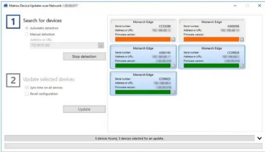
More info: Select Sync time on all devices to synchronize the internal device clocks across all updated devices. Select Reset configuration to reset the encoder settings of the device(s).
Step 6. If the Monarch EDGE device you are trying to update is already part of an EDGE environment (see "User and device management" on page 21), the following message will be displayed.
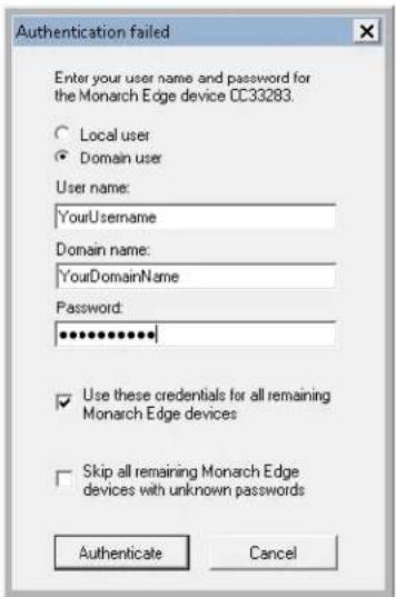
a. Click Local user.
b. Enter the credentials for the Monarch EDGE you want to update. You may need to contact your environment administrator for the information.
c. If the other Monarch EDGE devices you want to update share the same credentials, you can have the updater use them for those as well.
d. Click Authenticate.
Result of this task: The firmware on your Monarch EDGE device(s) has been updated.
Installing Monarch EDGE Control Hub
To install Matrox Monarch EDGE Control Hub, follow the steps below:
Step 1. Read "Update and installation prerequisites" on page 13.
Step 2. Download the Matrox Monarch EDGE Control Hub installation program from https://www.matrox.com/video/en/support/downloads/.
Step 3. Run the Matrox Monarch EDGE Control Hub installation program, click Next, then follow the on-screen instructions.
Step 4. When the installation is complete, click Finish.
Result of this task: Matrox Monarch EDGE Control Hub is installed on your system.
When done, remember: When you start Matrox Monarch EDGE Control Hub for the first time you will be asked to create your environment administrator account. For more information, see "Starting up Matrox Monarch EDGE Control Hub" on page 22.
Uninstalling or repairing Monarch EDGE Control Hub
To uninstall Matrox Monarch EDGE Control Hub, do one of the following:
-
Click Start > Control Panel > Programs and Features > Uninstall a program, click on Matrox Monarch EDGE Control Hub, then click Uninstall.
-
Run the Monarch EDGE Control Hub installer (see "Installing Monarch EDGE Control Hub" on page 16), then uninstall Monarch EDGE Control Hub, or repair the installation if it is already installed.
CHAPTER 4
Network management
This chapter includes the following topics:
- About Matrox Monarch EDGE device discovery
- Assigning a static IP address to a Monarch EDGE
• Monarch EDGE firewall requirements
About Matrox Monarch EDGE device discovery
Matrox Monarch EDGE Control Hub automatically detects and adds new devices to your Monarch EDGE environment. If devices aren't detected, Control Hub can scan one or more specific IP addresses or a range of IP addresses for Monarch EDGE devices.
Discovering devices automatically
After you install and run Monarch EDGE Control Hub for the first time, it automatically detects all the Monarch EDGE Series devices on the same subnet as your controller system through the UPnP (Universal Plug and Play) protocol.
Monarch EDGE Control Hub continually scans for devices whenever it is open. If a new device appears on the network, it will be displayed in Monarch EDGE Control Hub, but it may not yet be assigned to an environment by an environment administrator.
Discovering devices manually
If Monarch EDGE Control Hub doesn't automatically detect the Monarch EDGE devices on the same subnet as your controller system, you can manually add them to your environment.
To manually add a Monarch EDGE to your environment, follow the steps below:
Step 1. Go to Start > Programs > Matrox Monarch EDGE Control Hub.
Step 2. Open the Control Hub menu at the top left, then click on Manual device discovery.
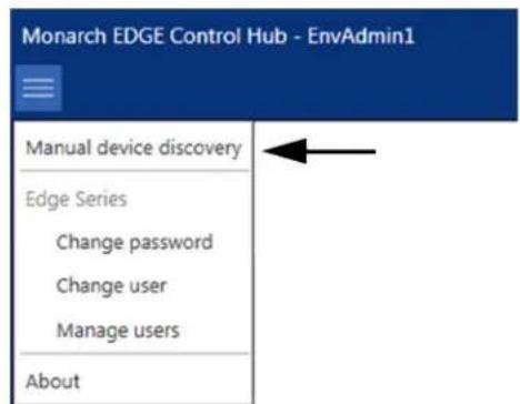
Step outcome: The Unit Discovery window opens.
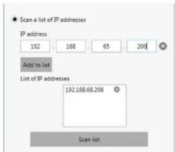
Step 3. Scan for specific Monarch EDGE devices:
a. Select Scan a list of IP addresses.
b. Enter the IP address of the Monarch EDGE to add.
c. Click Add to list.
d. If needed, repeat steps a to c to add more Monarch EDGE devices.
e. Click Scan list.
Step 4. Scan for devices across an IP range:
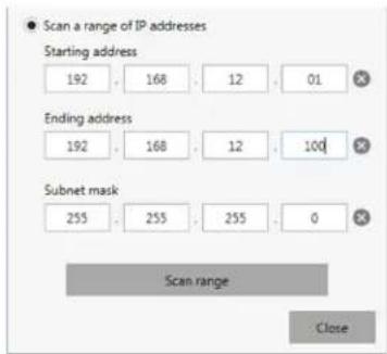
a. Select Scan a range of IP addresses.
b. Enter your Starting address.
c. Enter your Ending address.
d. Enter your Subnet mask.
e. Click Scan range.
Result of this task: Monarch EDGE Control Hub discovers the devices and you can add them to your environment.
Assigning a static IP address to a Monarch EDGE
After your Monarch EDGE has been connected, powered up, and has a DHCP-assigned IP address, you can assign it a static IP address from Monarch EDGE Control Hub (see "Configuring Network settings" on page 51) or from the LCD screen on the device as described below:
Step 1. As Monarch EDGE is scrolling through the status, press Menu.
Step 2. Go to Device config then press Enter.
Step 3. Go to Network Settings then press Enter.
Step 4. Go to Lan 1 or Lan 2 then press Enter.
Step 5. Go to Static then press Enter.
Step 6. Use the directional buttons to enter your desired IP address.
Step 7. Press Enter.
Result of this task: Your Monarch EDGE now has the static IP address you entered.
When done, remember: If your Monarch EDGE already has a static IP address, you can change it to a new static IP address using this same method.
Monarch EDGE firewall requirements
This section describes the firewall requirements for the Monarch EDGE device, firmware updater application, Monarch EDGE Control Hub, and Monarch EDGE Command Center.
| Network port | Type | Inbound | Outbound | Functionality |
| 20, 21 TCP | Yes N/A | FTP: File download (failsafe or firmware) | ||
| 69 | UDP | N/A | Yes | DHCP: DHCP client |
| 123 | UDP | N/A | Yes | NTP: Network Time Protocol |
| 443^1 | TCP Yes | N/A | HTTPS: Monarch EDGE Control Hub commands, authentication, firmware update, and tally. | |
| 80 | TCP Yes N/A | HTTP: Monarch EDGE Command Center. | ||
| 1500 (default) | UDP | N/A | Yes | MPEG-2 TS: Streaming (configurable) |
| 1500 (default) | UDP | Yes | Yes | SRT: Streaming (configurable) |
| 1900, 11900 UDP Yes | Yes | UPnP: Microsoft SSDP for discovery of UPnP devices | ||
| Ephemeral ^1 | UDP Yes Yes | RTP/RTCP: Audio and video streams and control. | ||
| 1935 TCP N/A Yes | RTMP: Streaming (configurable) | |||
| 3049 TCP Yes Yes | RTSP: Streaming (configurable) | |||
| 1022 - 1025 UDP Yes | Yes RTSP: base ports for talkback | |||
- Minimum requirements.
CHAPTER 5
User and device management
This chapter includes the following topics:
- About User and Device Management
- Starting up Matrox Monarch EDGE Control Hub
• Environment administrator accounts - User accounts
- Managing users and device permissions
About User and Device Management
You can use either Monarch EDGE Control Hub or Monarch EDGE Command Center to manage users and their access to devices. The user management capability of Command Center is a simplified version of what you can do in Control Hub.
Monarch EDGE Control Hub: The Control Hub software enables you to remotely control, manage, and configure your Monarch EDGE devices from a controller system in your Monarch EDGE environment. With Control Hub, you can access any device on your DHCP-enabled network, including devices on different subnets. Anyone can open Matrox Monarch EDGE Control Hub to view the discovered Monarch EDGE devices, but you must be an environment administrator or an authorized user with the proper credentials to modify device settings.
Monarch EDGE Command Center: As a web-based configuration tool, Command Center offers simplified user management capability for a single Monarch EDGE device. You cannot use Command Center to view all EDGE devices on your network or to configure users on multiple EDGE devices. If a particular EDGE device has already been configured in Control Hub, the user management settings are inherited when you access the same device in Command Center.
This chapter only describes user management with Monarch EDGE Control Hub. For more information on how to manage users and devices on Monarch EDGE Command Center, see the chapter "Monarch EDGE Command Center configuration" on page 59.
Starting up Matrox Monarch EDGE Control Hub
When you install and start Matrox Monarch EDGE Control Hub for the first time, you will be asked if you are an environment administrator.
Monarch EDGE Control Hub

Are you a Edge environment administrator?
Yes
As a Edge environment administrator, enter your user name and password in the next dialog box, then select the devices on which you want administrator rights, create users on these devices, and set permissions for these users.
No
As a Monarch EDGE Control Hub user, you can only view the settings of a Edge device. To be able to reboot or edit the settings of a device, contact your Edge environment administrator to obtain a user name and password. Once your administrator provides your user name and password, select "Define user" in the Monarch EDGE Control Hub main menu, and enter that information.
Yes
No
- If you are a Monarch EDGE environment administrator, click Yes. You will then be asked to create your environment administrator username and password. For more information, see "Environment administrator accounts" on page 22.
- If you are not a Monarch EDGE environment administrator, click No. You will then be asked to enter the username and password provided by your environment administrator for use with the devices they have specified. For more information, see "User accounts" on page 24.
Environment administrator accounts
This section explains what Matrox Monarch EDGE environment administrators are and describes how to create an environment administrator account in Monarch EDGE Control Hub.
About environment administrators
As an environment administrator, you will have full administrator rights on the Matrox Monarch EDGE devices you choose to control. You take control of the devices after creating your environment administrator username and password by selecting the devices from a displayed list of available devices.
Therefore, you can think of “environments” as groups of Monarch EDGE devices all controlled by the same environment administrator account. By becoming the environment administrator for your devices, you can then create user accounts for others with the proper permissions to modify the device settings.
Please note the following about environment administrator accounts:
• There can be more than one.
You can have multiple environment administrators controlling different groups of devices. For example, if there are 10 Monarch EDGE devices available on your network, you could have two environment administrators each controlling five devices.
- A factory reset on a device purges the account.
Performing a factory reset on a Monarch EDGE device will also reset the environment administrator account on it. The device will then be available on the network again as if it were a new device. All user accounts associated to the device are purged as well. A device reboot does not affect the environment administrator or user accounts.
- You don't need one to find Monarch EDGE devices.
You do not need to be an environment administrator to find specific Monarch EDGE devices, or a range of devices, on the network. For more information on device discovery, see "Network management" on page 17.
- They can create other environment administrators.
Only environment administrators can create and edit other environment administrator accounts. The “Edit users” permission has similar rights (e.g. see other users, edit permissions, etc) but the key difference is that a regular user cannot create or edit an administrator account, even if they have the “edit users” permission.
Creating an environment administrator account
You must create an environment administrator account when you install and start Monarch EDGE Control Hub for the first time. Once you have your administrator account, you can create as many other administrator or user accounts as needed.
To create an administrator account, follow the steps below:
Step 1. Read "About environment administrators" on page 23.
Step 2. Go to Start > Programs > Matrox Monarch EDGE Control Hub.
Step 3. If this is the first time you start Control Hub, you will be asked if you are an environment administrator. ClickYes.
Step 4. Enter the username and password you want to use for this environment administrator account, then click Apply.
Step outcome: Your environment administrator account is created. Now you need to select which Monarch EDGE devices this account controls.
Step 5. From the available Monarch EDGE devices displayed, click on the ones you want to control, then click Add devices.
More info: Shift-click or Ctrl-click selects multiple devices.

Result of this task: You are now the environment administrator for the Monarch EDGE devices you selected.
When done, remember: You will need to add users and give them permission to modify settings on the devices you control. For more information, see "User accounts" on page 24.
User accounts
This section explains what Matrox Monarch EDGE user accounts are and describes how to create a user account in Control Hub.
About user accounts
User accounts are created by the environment administrator(s). User accounts are created on specific Monarch EDGE devices that are part of an environment. For example, an environment administrator cannot create a user without also immediately assigning that user to at least one Monarch EDGE device.
Users can be granted the following permissions:
Administrator: An environment administrator can create other administrators by granting a user administrator rights. Administrators can create, delete, and edit other users, as well as do all the other actions listed below. They can also take control of other available Monarch EDGE devices on the network, thereby becoming environment administrators themselves. For more information on this process, see "Environment administrator accounts" on page 22.
Apply changes: This allows users to apply settings changes to Monarch EDGE devices (e.g. change encoder settings, start/stop encoding, etc).
Edit users: This allows users to edit their own credentials and permissions.
Reboot devices: This allows users to reboot Monarch EDGE devices from the Control Hub application (any device can be physically rebooted if needed).
Creating a user account
To create a user account, follow the steps below (you must be an environment administrator):
Step 1. Go to Start > Programs > Matrox Monarch EDGE Control Hub.
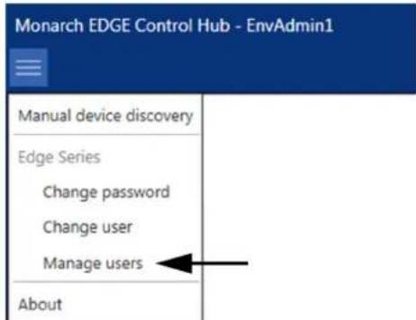
Step 2. Open the Control Hub menu at the top left, then click on Manage users. Example: In this example, the environment administrator is EnvAdmin1.
Step 3. Type the username you want in the field provided, then click Add user.
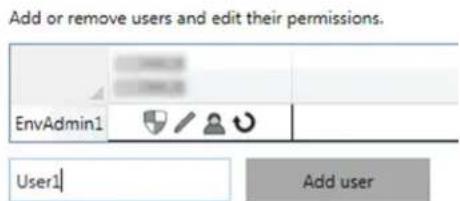
Step outcome: The new user will appear under the EnvAdmin1 account.
Step 4. Click (+) to access the Permissions menu on the far-right of the Monarch EDGE Control Hub interface, then give your user the desired permissions. Example: Let's say you only want this user to modify settings, not to edit users or reboot Monarch EDGE devices.
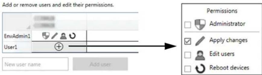
Step 5. Click Apply.
Result of this task: Your new Monarch EDGE user is created and (in this case) can only modify settings on the devices in their environment.
When done, remember: If you have multiple Monarch EDGE devices in your environment, you can specify which devices your users have access to, and what they can do on each device. For more information, see "Managing users and device permissions" on page 26.
Managing users and device permissions
This section includes topics on the various user and device management tasks you can perform in the Matrox Monarch EDGE Control Hub.
Transferring control to a different environment administrator
If you have an environment administrator account controlling one or more Monarch EDGE devices, and you want to transfer control of those devices to a different administrator account, you can do so as follows:
Step 1. Go to Start > Programs > Matrox Monarch EDGE Control Hub.
Step outcome: Monarch EDGE Control Hub opens and the Monarch EDGE devices on the network are displayed.
Step 2. Open the Control Hub menu at the top left, then click on
Manage users.
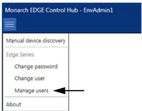
Step 3. Create a new user (see Creating a user account) and give the new user administrator rights.
Step 4. Open the Control Hub menu at the top left again, but this time click on Change user.
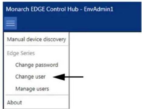
Step 5. Enter the username and password of the user you just created in Step 3.
Step 6. Click Apply.
Step outcome: You are now logged on to the environment as the new user you created, with the same administrator rights as the original environment administrator.
Step 7. From the list of users displayed, click on the original environment administrator account, then click Delete user.
Step 8. Click Yes to confirm, then Apply to apply the change to the environment.
Result of this task: You have created a new environment administrator to replace the original environment administrator. You can do this as many times as needed.
When done, remember: You can always factory reset any Monarch EDGE device to completely remove all environment administrator control from it.
Changing the environment password
Environment administrators can change the password across all devices in the environment. To change the environment password, follow the steps below:
Step 1. Go to Start > Programs > Matrox Monarch EDGE Control Hub. Step outcome: Control Hub displays the Monarch EDGE devices.
Step 2. Open the Control Hub menu at the top left, then click on Change password.
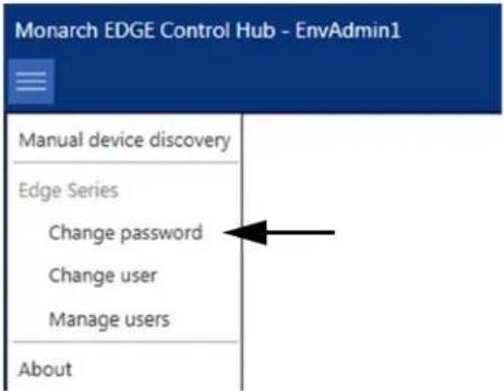
Step 3. Enter the password to use for the devices in your environment.
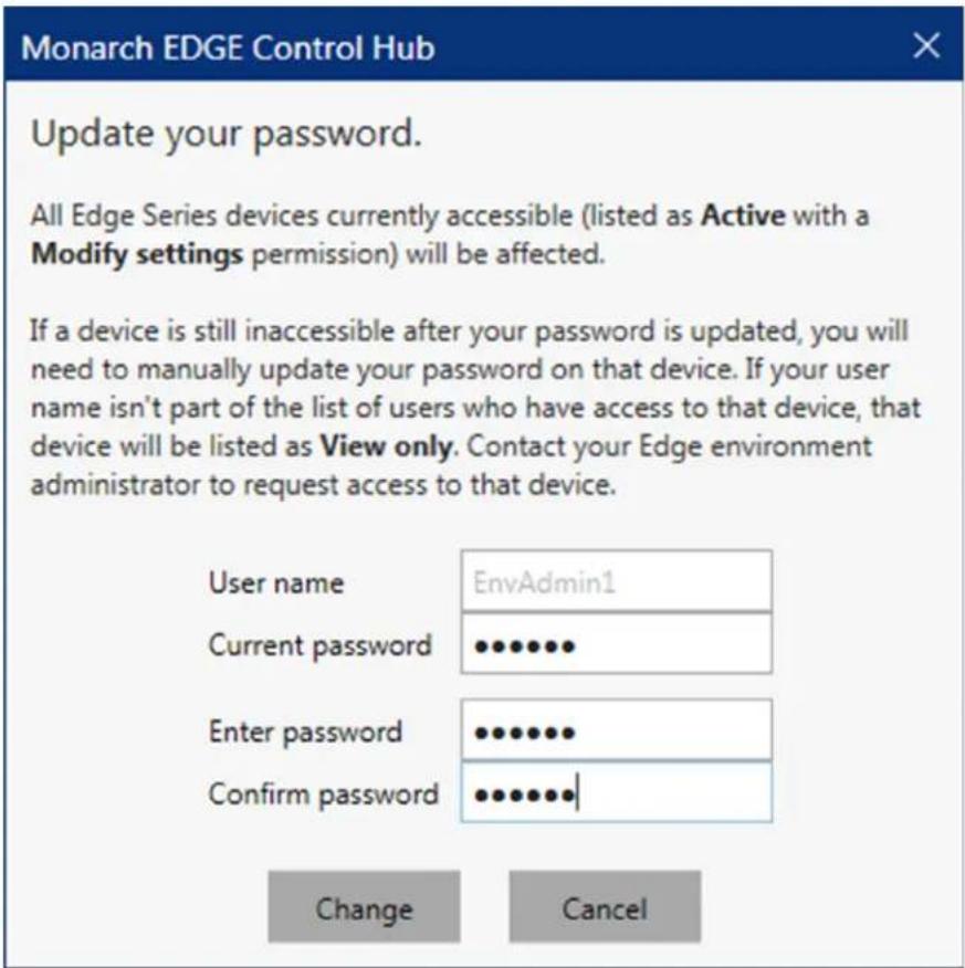
Step 4. Click Change.
Result of this task: The environment password has been changed.
Changing user accounts
To change the user logged on to the Monarch EDGE Control Hub, follow the steps below:
Step 1. Go to Start > Programs > Matrox Monarch EDGE Control Hub.
Step outcome: Control Hub displays the Monarch EDGE devices.
Step 2. Open the Control Hub menu at the top left, then click on Change user.
Example: The environment administrator EnvAdmin1 is currently logged on.
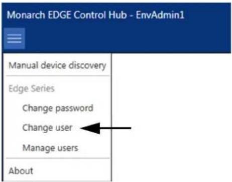
Step 3. Enter the user name and password of the user that wants to log on.
Example: In this case, a different administrator EnvAdmin2 will log on. More info: The user must have already been created (see "Creating a user account" on page 25).
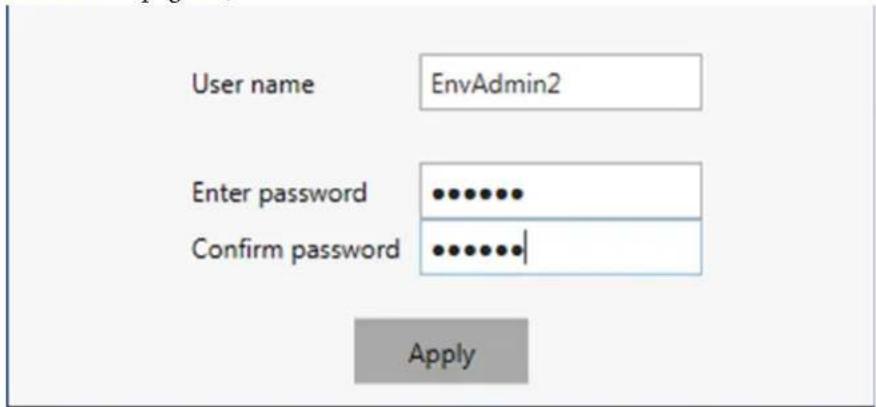
Step 4. Click Apply.
Result of this task: The account EnvAdmin2 is now logged on to Monarch EDGE Control Hub.
When done, remember: The account currently logged on to Monarch EDGE Control Hub is displayed at the top left of the application in the title bar, and is also displayed on top in the Manage users section.
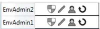
Managing user accounts and permissions
Environment administrators create and/or delete users, and specify users' permissions. To create, delete, or manage user permissions, follow the steps below:
Step 1. Go to Start > Programs > Matrox Monarch EDGE Control Hub.
Step outcome: Control Hub displays the Monarch EDGE devices.
Step 2. Open the Control Hub menu at the top left, then click on Manage users.
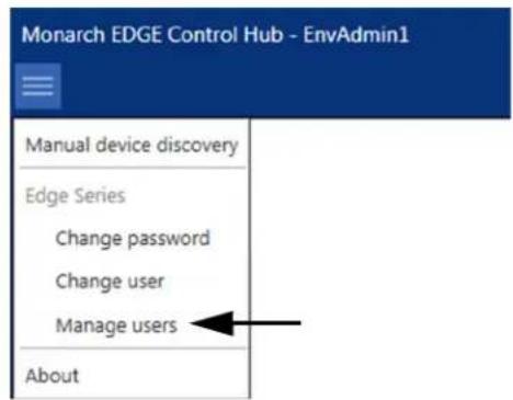
Step outcome: The user accounts are displayed along with their permissions.
Step 3. Modify your users as needed.
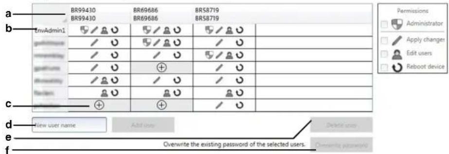
a. The devices controlled by the current environment administrator. Each column displays the device, its users, and their permissions.
b. The list of users on this environment. Click on a user to select it. Shift-click or Ctrl-click selects multiple users. The username at the top of the list is the one currently logged on to Control Hub.
c. Adds the user to the device and allows access to the permissions menu.
d. Adds a new user (see "Creating a user account" on page 25).
e. Deletes the selected user. Shift-click or Ctrl-click selects multiple users.
f. Overwrites the selected users' passwords. Shift-click or Ctrl-click selects multiple users.
Step 4. Click Apply.
Result of this task: Your user modifications have been applied.
CHAPTER 6
Monarch EDGE Control Hub configuration
This chapter includes the following topics:
• Monitoring Monarch EDGE devices
- About the Monarch EDGE Control Hub user interface
- Configuring Encoder Processing settings
- Configuring Decoder Processing settings
- Configuring Network settings
- Configuring Date and Time settings
- Configuring Genlock settings
- Configuring DP Output settings
- Configuring Tally settings
- Configuring Talkback settings
- Managing Logs
- Managing configurations
- Grouping Monarch EDGE devices
Monitoring Monarch EDGE devices
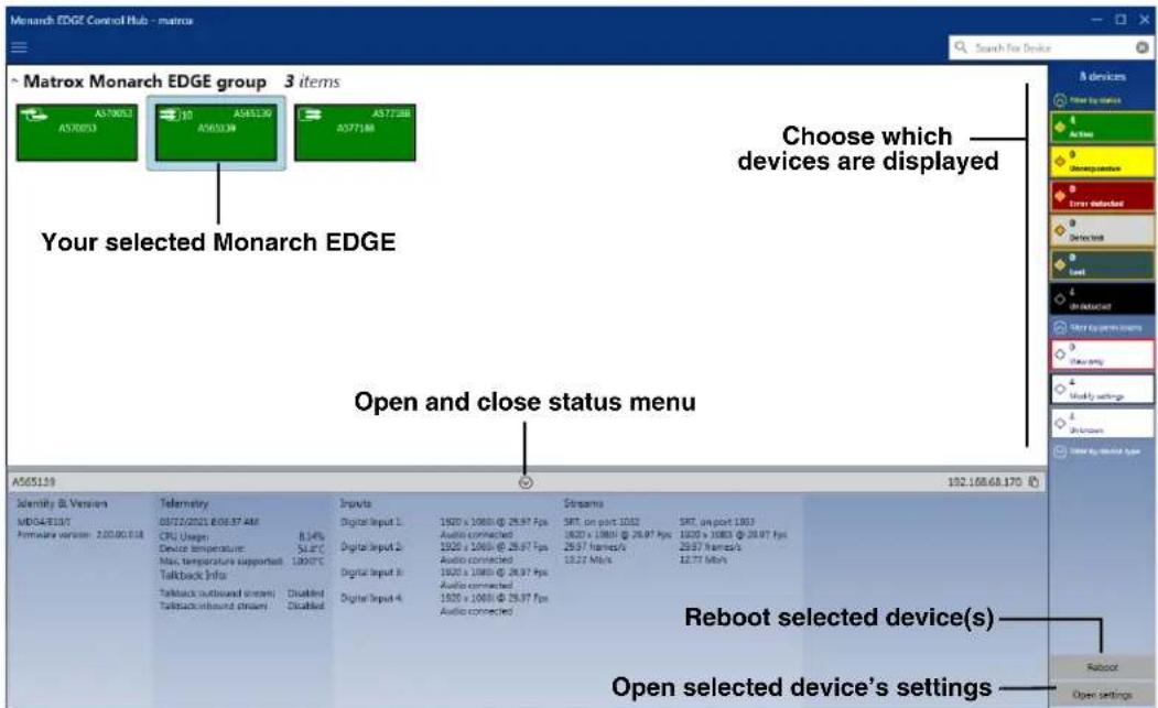
From the main Monarch EDGE Control Hub page, you can quickly view the status of all your Monarch devices by opening the status menu. The status menu provides a variety of information at a glance, such as which inputs are connected, what their resolutions are, and displays the currently active streams.
In the image below, for illustration purposes, three active Monarch EDGE devices are shown: a Monarch EDGE E4 (→), a Monarch EDGE D4 (→), and a Monarch EDGE S1 (→). Your Monarch EDGE environment will likely be different, and may show both active and inactive devices, as well as unresponsive devices or devices with other statuses.
About the Monarch EDGE Control Hub user interface
After you select a Monarch EDGE device to configure from the Control Hub's main page (see "Monitoring Monarch EDGE devices" on page 32), you will see the configuration page which consists of the following sub-sections:
Processing / Encoding / Decoding: These are the main settings related to video and audio streaming. Depending on which Monarch EDGE you have, you will see either the Processing sub-section (Monarch EDGE E4 and D4) or the Encoding and Decoding sub-sections (Monarch EDGE S1). For more information, see "Using the contextual menu for encoder
and decoder settings" on page 33, "Configuring Encoder Processing settings" on page 35, and "Configuring Decoder Processing settings" on page 48.
Network: These are the network settings that allow you to set DHCP or static IP addressing for LAN 1 and/or LAN 2 (if applicable). For more information, see "Configuring Network settings" on page 51.
Date and time: These are the settings that allow you to configure time-related options such as specifying an NTP server, or setting the time zone of your Monarch EDGE. For more information, see "Configuring Date and Time settings" on page 52.
Genlock: This is where you enable the genlock functionality for the Monarch EDGE E4 and set the genlock output to sync to NTSC or PAL frame rates. For more information, see "Configuring Genlock settings" on page 53. The Monarch EDGE D4 and Monarch EDGE S1 genlock settings are described in "Configuring Decoder Processing settings" on page 48.
DP Output: This is where you can enable the video preview option that uses the Monarch EDGE's DisplayPort connection. Please note that this feature can affect the EDGE's processing performance. It is not recommended to use a 4K monitor for preview. For more information, see "Configuring DP Output settings" on page 54.
Tally and Talkback: This is where you enable and use the Tally and Talkback functionality of the Monarch EDGE For more information, see "Configuring Tally settings" on page 54 and "Configuring Talkback settings" on page 56.
Logs: This where you can download the logs to be used for troubleshooting your Monarch EDGE, if needed. For more information, see "Managing Logs" on page 57.
Using the contextual menu for encoder and decoder settings
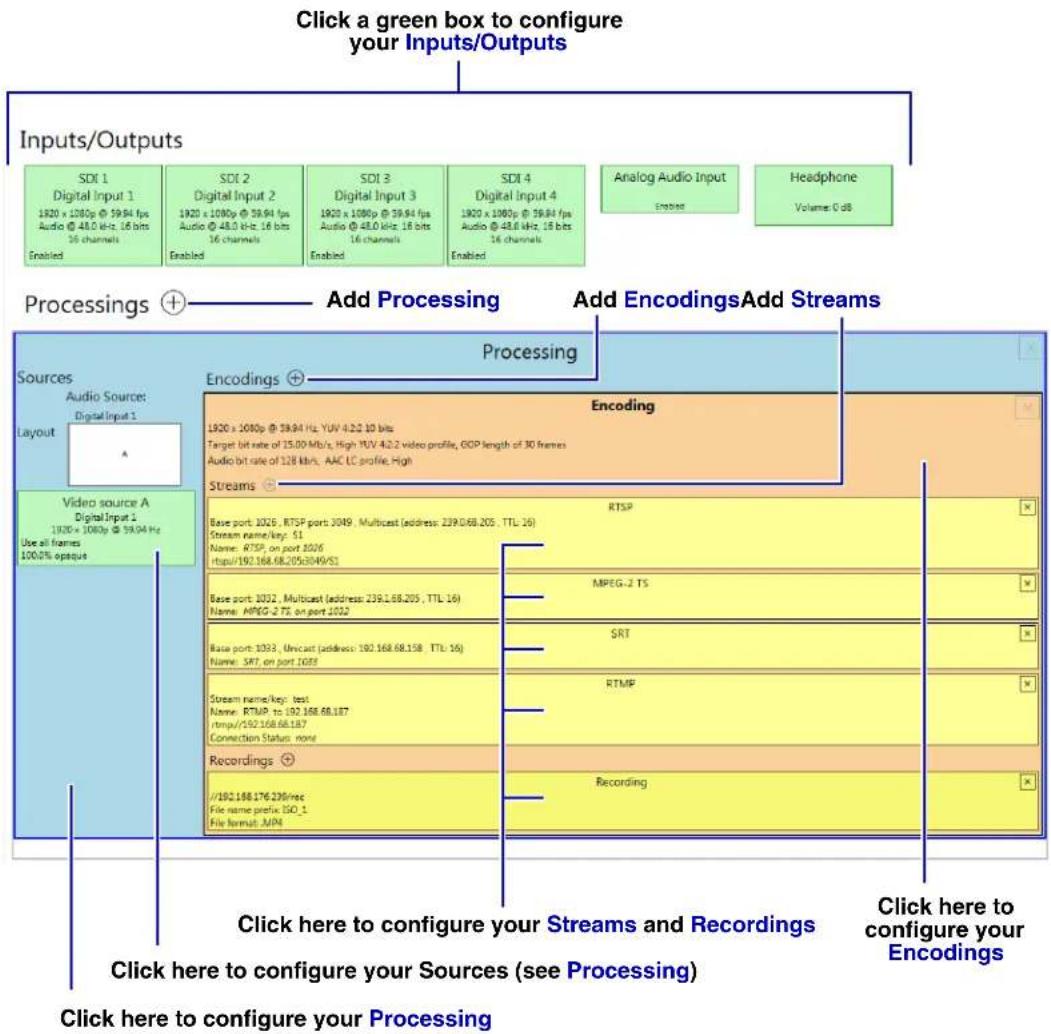
The Processing section of the Monarch EDGE E4 and D4 Control Hub user interface, and the Encoding and Decoding sections of the Monarch EDGE S1 Control Hub user interface, allow you to configure your settings in a single window by using a contextual menu that changes depending on where you click.
In the following image, if you click on any of the areas indicated, the menu on the right of the Monarch EDGE Control Hub screen will change to display the relevant settings. The active area of Control Hub will be a darker shade of its color (e.g. in the image, SDI 1 is selected).
NOTE The image below shows the encoder settings for a Monarch EDGE E4, but the user interface works the same way for Monarch EDGE D4 and Monarch EDGE S1; that is, as a menu that dynamically displays the relevant configuration settings depending on where you click.
This image does not necessarily represent a realistic user scenario, it is intended simply to show you where in the user interface you can click to access the desired settings.
flowchart
graph TD
    A["Click a green box to configure your Inputs/Outputs"] --> B["Inputs/Outputs"]
    B --> C["Processings"]
    C --> D["Add Processing"]
    D --> E["Add Encodings Add Streams"]
    E --> F["Processes"]
    F --> G["Encoding"]
    G --> H["Add Encoding"]
    H --> I["Recording"]
    I --> J["Click here to configure your Streams and Recordings"]
    J --> K["Click here to configure your Sources (see Processing)"]
    K --> L["Click here to configure your Processing"]
Clicking any of the above areas shows the settings in the contextual menu, as follows.

flowchart
graph LR
    A["Video source A\nDigital A/V Input 1\nScaled to nearest edge\nUse all frames\n100.0% opaque"] --> B["Click Video source A to display the settings in the contextual menu."]
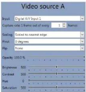
After changing settings, you need to click Apply or Cancel at the bottom right of the page.
Configuring Encoder Processing settings
This section describes the Monarch EDGE Control Hub Processing settings for your Monarch EDGE E4, and the Encoding settings for Monarch EDGE S1.
Inputs/Outputs
This section describes the Inputs/Output settings in Monarch EDGE Control Hub.
Monarch EDGE E4 settings
| SDI 1Digital A/V Input 11920 x 1080i @ 29.97 HzAudio @ 48.0 kHz, 16 bitsStereoEnabledYUV 4:2:2 10 bits | SDI 2Digital A/V Input 2(no video)(no audio)Enabled (needs signal)YUV 4:2:2 10 bits | SDI 3Digital A/V Input 3(no video)(no audio)Enabled (needs signal)YUV 4:2:2 10 bits | SDI 4Digital A/V Input 4(no video)(no audio)Enabled (needs signal)YUV 4:2:2 10 bits | Analog Audio Input(connection detected)Disabled | HeadphoneVolume: 0 dB |
Monarch EDGE S1 settings
| SDI 1Digital Input 1(no video)(no audio)Enabled (needs signal) | Analog Audio InputDistilled | HeadphoneVolume: 0 dB |
| Connector Setting Description | ||
| SDI Inputs 1 to 4 (Monarch EDGE E4) ^1 SDI Input 1 (Monarch EDGE S1) | Enable input | Enable the input. Monarch EDGE detects the input resolution but you still need to enable the input. Monarch EDGE will not stream unless there is an input connected to it. |
| Input name | Give the input a specific name. | |
| Analog Audio Input ^2 | Enable input | Enable your XLR analog audio input. |
| Gain | Increase or decrease the amplitude of your analog audio input. | |
| Headphone | Audio source | Select which audio source to output through the Monarch EDGE headphone jack. |
| Volume | Increase, decrease, or mute the headphone volume. | |
-
The audio value shown here is what the SDI input is feeding to the Monarch EDGE's codec. For example, even if your video contains 24-bit audio, the AAC codec can only handle 16-bit so that is what is displayed.
-
Available only when the Talkback feature is disabled.
Processing
This section describes the Process settings in Monarch EDGE Control Hub.
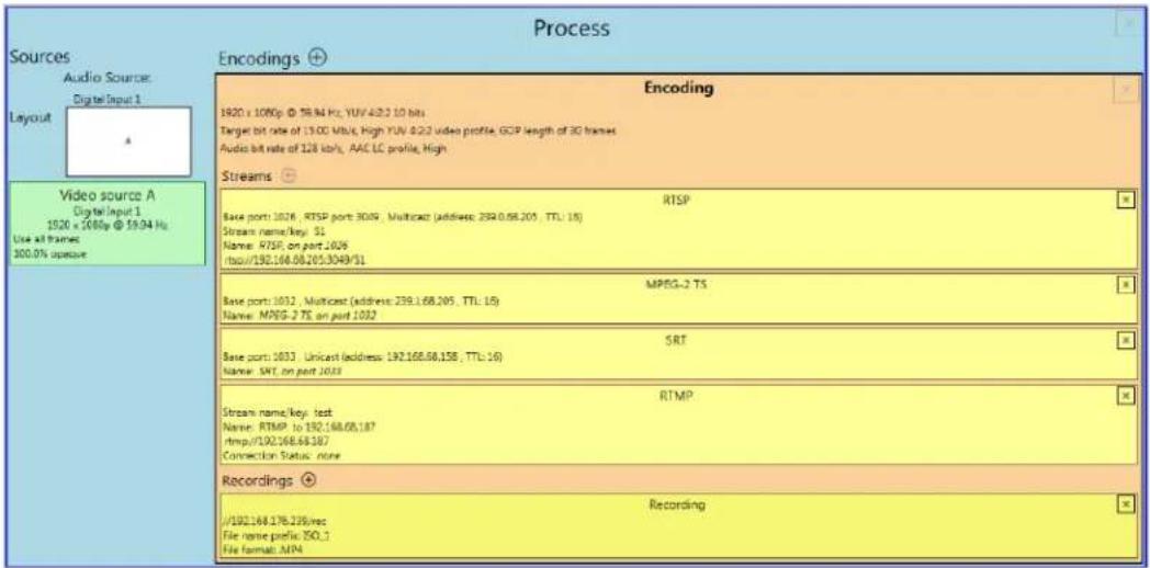
| Setting Description | |
| Audio | |
| Audio source | The source of the audio signal to use. |
| Video | |
| Layout | Select the video layout and the number of sources to use. |
| Follow source input | By default, Monarch EDGE will follow the frame size, frame rate, background color, and pixel format of the source video. If you want to customize these settings, clear this option and the settings become available for modification. For interlaced signals, you must select this option for the interlaced nature of the signal to be preserved in the encoding process. |
| Frame size | The width and height, in pixels, of the source. If the layout of your sources uses a height or width that's smaller than your frame size, black borders may appear on both sides, or on the top and bottom, of the frame. The width ranges from 64 to 4096 and must be a multiple of 16. The height ranges from 64 to 4096 and must be an even number. |
| Frame rate | The frame rate, in FPS (frames per second), for the source. |
| Background color | The background color for your source. If the layout of your sources uses less height or width than your frame size, the borders will use the background color. If no video is captured for your source, the background color is shown instead. |
| Pixel format | The pixel format to define the quality of your image, and the pixel depth for each color in the image format. A higher YUV format and pixel depth provides a higher quality image and requires more resources to process. Only certain pixel formats may be available. |
| Video sources | |
| Input | Select the input to use for your source. |
| Capture rate | Select the rate of capture per input. |
| Scaling | Select how to scale your video:Unscaled from top left The video is unscaled and positioned in the top left corner of the display area. If the display resolution of the video is bigger than the display area, the video will be cropped.Unscaled centered The video is unscaled and centered in the display area. If the display resolution of the video is bigger than the display area, the video will be cropped.Stretched to all edges The video is stretched to fit the entire display area without respecting the aspect ratio of the original video. If the aspect ratio of the video and the display area don't match, the video may be distorted.Scaled to all edges The video is scaled to fit the entire display area while respecting the aspect ratio of the original video. The video is centered in the display area. If the aspect ratio of the video and the display area don't match, the video will be cropped.Scaled to nearest edge The video is scaled to fit to the display area while respecting the aspect ratio of the original video. The video is centered in the display area. If the aspect ratio of the video is not scaled to the display area, black borders will appear on both sides of the video or above and below. The video isn't cropped. |
| Pivot | Change the orientation of your source:0 degrees No pivot is applied.90 degrees clockwise The source is rotated 90 degrees clockwise.180 degrees The source is rotated 180 degrees.90 degrees counterclockwise The source is rotated 90 degrees counterclockwise. |
| Setting Description | |
| Flip | Select the plane along which the source is flipped:None No flip is applied.Vertically The source is flipped along the vertical plane. The top becomes the bottom.Horizontally The source is flipped along the horizontal plane. The right side becomes the left.On both axes The source is flipped along the vertical plane and the horizontal plane. This is visually similar to rotating 180 degrees. |
| Opacity | Increase or decrease how opaque the source video appears. The default is 100%. |
| Brightness | Increase or decrease how light or dark the colors appear. The default is 500. |
| Contrast | Change the difference in brightness between the lightest and darkest colors. The default is 500. |
| Hue | Increase or decrease the tint or tone of colors. The default is 0. |
| Saturation | Increase or decrease the depth of the colors. The default is 500. |
Encodings
This section describes the Encoding settings in Monarch EDGE Control Hub
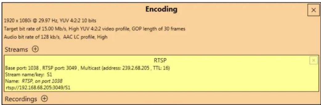
NOTE One RTSP stream is active by default when you create a new Encoding. For more information, see "Streams" on page 42.
| Setting Description | |
| Include | Select the signals to include (Audio only, Video only, or Audio and video) in your encoding. |
| Setting Description | Video |
| Force encoding size | Select to increase or reduce the captured video size before encoding. |
| Frame size | Specify the width and height, in pixels, of the video up to the width and height of the original video layout. If your canvas uses a different size, your encoder scales the video to the specified size (image may be distorted). The width ranges from 64 to 3840 and must be a multiple of 16. The height ranges from 64 to 2160 and must be an even number. |
| Scaling | Select how to scale your video:Unscaled from top leftThe video is unscaled and positioned in the top left corner of the display area. If the display resolution of the video is bigger than the display area, the video will be cropped.Unscaled centeredThe video is unscaled and centered in the display area. If the display resolution of the video is bigger than the display area, the video will be cropped.Stretched to all edgesThe video is stretched to fit the entire display area without respecting the aspect ratio of the original video. If the aspect ratio of the video and the display area don't match, the video may be distorted.Scaled to all edgesThe video is scaled to fit the entire display area while respecting the aspect ratio of the original video. The video is centered in the display area. If the aspect ratio of the video and the display area don't match, the video will be cropped.Scaled to nearest edgeThe video is scaled to fit to the display area while respecting the aspect ratio of the original video. The video is centered in the display area. If the aspect ratio of the video is not scaled to the display area, black borders will appear on both sides of the video or above and below. The video isn't cropped. |
| Pivot | Change the orientation of your source:0 degrees No pivot is applied.90 degrees clockwiseThe source is rotated 90 degrees clockwise.180 degrees The source is rotated 180 degrees.90 degrees counterclockwise The source is rotated 90 degrees counterclockwise. |
| Setting Description | |
| Flip | Select the plane along which the source is flipped:None No flip is applied.Vertically The source is flipped along the vertical plane. The top becomes the bottom.Horizontally The source is flipped along the horizontal plane. The right side becomes the left.On both axes The source is flipped along the vertical plane and the horizontal plane. This is visually similar to rotating 180 degrees. |
| Force pixel format | The pixel format defines the quality of the image encoded. YUV refers to the color format used to receive each block of bits in the video signal. The format is followed by the pixel depth used for each color in the image format. A higher YUV format and pixel depth provides a higher quality image and requires more resources to process. |
| Encoding profile^1 | Select an encoding profile for your signal. Changing the encoding profile may prevent your decoder from streaming.BaselineMainHighHigh 10-bit (if available)High YUV 4:2:2 (if available) |
| Target bit rate | The target bit rate, in Mb/s (Megabits per second), for encoding. The actual bandwidth used by your encoder varies according to your source and encoding method. The default is 15 Mb/s. A lower target bit rate may result in lower image quality. A higher target bit rate limit may result in lower performance or may require higher network bandwidth. |
| Bit rate control | Select one of the following:Use variable bit rateUse constant bit rate |
| Maximum bit rate | The maximum bit rate for variable bit rate encoding. When encoding, the processor attempts to use the target bit rate but may use up to the maximum bit rate specified here.The default is 22.5 Mb/s. The maximum bit rate you can set is 120 Mb/s. |
| Quantization parameters | The range used to compress the various frames in your GOP. A high maximum increases the level of compression of the frame and should decrease the bit rate but may decrease the image quality. |
| Setting Description | |
| Encoding mode | Select one of the following:Optimized for low latency ^2 Potentially reduces the delay between the time the video is captured on the encoder and the time it's shown on a monitor connected to a decoder (not supported on third-party decoders).Favor image quality ^3 Favors image quality over latency, but may introduce extra frames of delay in certain circumstances. Matrox highly recommends this setting when using default encoding parameters. |
| Force CAVLC entropy encoding | Enable this to force the use of context adaptive variable length coding (CAVLC) entropy encoding. Enabling this option overrides the default entropy encoding selection (CABAC). |
| GOP length | The number of frames from one complete frame (I-frame) to another. A higher GOP length increases the compression level but may result in a lower quality image.The default GOP length is 30. |
| Insert P-frame every | Enter the number of frames before a P-frame is inserted. All other frames are B-frames. A higher number of frames before inserting a P-frame increases the quality of the image but may result in a loss of performance.The minimum and default value is 1 (indicating no B frames ^4 ). The maximum value is 4. |
| Audio | |
| Bit rate | Select the audio bit rate, in kbps, for your audio transmission. A higher bit rate produces a sound quality closer to the source quality but requires more bandwidth.The value ranges from 32 to 576. The default is 128. |
| AAC encoder | Select one of the following:AAC LC Allowed bit rate range is 32 to 576 kbps.AAC HEv1 Allowed bit rate range is 32 to 288 kbps.AAC HEv2 Allowed bit rate range is 32 to 144 kbps. |
| AAC quality | Force the use of encoding complexity (low to high) to improve the quality of compressed audio. Adjusting these settings doesn't affect the audio sample rate, target bit rate, or latency.LowMediumHigh |
| Use temporal noise shaping | This reshapes the quantization noise over time to improve the quality of the audio signal. This option is enabled by default. |
| AAC format | Select one of the following:ADTSNo container format |
- The encoding profile you want may not be available depending on the pixel format of your video.
- Low latency cannot be maintained if you change the Monarch EDGE Encoder settings while streaming to the Monarch EDGE Decoder. To re-establish low latency, go to your Monarch EDGE Decoder's SDI Output settings, disable the output, set Output stream selector to None, then click Apply. After you have disabled the output and the stream, re-enable both of them to ensure low latency is restored to your stream.
- The Optimized for low latency mode does not necessarily result in improved latency, as you may have the same latency performance as the Favor image quality mode. However, the Favor image quality mode will always result in a better quality image and is recommended unless specific encoder uses cases are validated.
- There are no B frames in low latency mode.
Streams
This section describes the Streams settings in Monarch EDGE Control Hub.
| RTSP | |
| Base port: 15012 , RTSP port: 3049 , Multicast (address: 224.30.20.10 , TTL: 16)Stream name/key: ES2Name: New encoder addedrtsp://192.168.68.228:3049/ES2 | |
| RTMP | |
| Stream name/key: S1Name: RTMP, toYourPushLocation | |
| MPEG-2 TS | |
| Base port: 1027 , Multicast (address: 239.0.68.228 , TTL: 16)Name: MPEG-2 TS, on port 1027 | |
| SRT | |
| Base port: 1028 , Unicast (address: 12.34.56.78 , TTL: 16)Name: SRT, on port 1028 |
| Setting Description | |
| RTSP | |
| Enable stream | Enable or disable your stream. |
| Audio pair selection | Select the audio pair you want to encode. You can select one pair per stream, but you can create additional streams and select a different audio pair for each of them (e.g. use the same stream but with a different language for each other audio pair). |
| Base port | The port number used to transmit your stream. |
| Name | Enter a name for your stream. |
| Network interface | Select LAN1 or LAN2 |
| RTSP port | The RTSP port number used to transmit your stream. |
| Stream name/key | Enter a suffix as part of your stream address. If you're using a media player to decode your stream, the media player may require this as part of the stream address to connect to a stream. |
| Time to live | The number of hops or network nodes (such as network switches or routers) through which a multicast signal can travel. Once the TTL number is reached, the receiving network node prevents the signal broadcast further down the network. The value ranges from 1 to 255. The default is 16. |
| Routing scheme | Select one of the following:Unicast When selecting unicast, you need to specify the destination IP address of the stream. You can enter a valid IP address or host name.Multicast Enter a Multicast address. Using multicast may require additional network configuration to support the transmission protocol (some network switches and routers can block multicast signals). For more information, contact your network administrator. To also allow unicast connections, enable the Allow unicast connec-tions option. |
| RTMP | |
| Enable stream | Enable or disable your stream. |
| Audio pair selection | Select the audio pair you want to encode. You can select one pair per stream, but you can create additional streams and select a dif-ferent audio pair for each of them (e.g. use the same stream but with a different language for each other audio pair). |
| Push location | The path of your RTMP stream. |
| Name | Enter a name for your stream. |
| Network interface | Select LAN1 or LAN2 |
| Stream name/key | Enter a suffix as part of your stream address. If you're using a media player to decode your stream, the media player may require this as part of the stream address to connect to a stream. |
| Use authentication | Enable this if you're using an authentication server, then enter your credentials (User name and Password). |
| MPEG-2 TS | |
| Enable stream | Enable or disable your stream. |
| Audio pair selection | Select the audio pairs you want to encode. You can select up to four pairs (i.e. eight audio channels) per stream, but you can create additional streams and select different audio pairs for each of them.NOTE The embedded audio channel mapping from Monarch EDGE Encoder to Decoder will match, regardless of which audio channels you select. For example, if you select audio pairs 1-2 and 13-14 on the encoder side, they will be mapped to the same loc tions on the decoder side. The other audio channels will be blank. |
| Base port | The port you are transmitting to on the receiving device. |
| Name | Enter a name for your stream. |
| Network interface | Select LAN1 or LAN2 |
| Time to live | The number of hops or network nodes (such as network switches or routers) through which a multicast signal can travel. Once the TTL number is reached, the receiving network node prevents the signal broadcast further down the network. The value ranges from 1 to 255. The default is 16. |
| Routing scheme | Select one of the following:· Multicast Enter a Multicast address. Using multicast may require additional network configuration to support the transmission protocol (some network switches and routers can block multicast signals). For more information, contact your network administrator. To also allow unicast connections, enable the Allow unicast connec-tions option.· Unicast When selecting unicast, you need to specify the destination IP address of the stream. You can enter a valid IP address or host name. |
| SRT ^1 | |
| Enable stream | Enables the SRT stream to the specified location. |
| Audio pair selection | Select the audio pairs you want to encode. You can select up to four pairs (i.e. eight audio channels) per stream, but you can create additional streams and select different audio pairs for each of them.NOTE The embedded audio channel mapping from Monarch EDGE Encoder to Decoder will match, regardless of which audio channels you select. For example, if you select audio pairs 1-2 and 13-14 on the encoder side,they will be mapped to the same loc tions on the decoder side. The other audio channels will be blank. |
| Setting Description | |
| SRT Protocol | Set your SRT protocol to Caller, Listener, or Rendezvous.Caller: The device must know the public IP address and port number of the Listener-modener: The device only needs to know that it should listen for an SRT stream on a certain port.Rendezvous: Allows two devices to negotiate an SRT session over a mutually agreed upon port. Both source and destination must be in Rendezvous mode. |
| Base port | The port you are transmitting to on the receiving device. |
| Name | Enter a name for your stream. |
| Network interface | Select LAN1 or LAN2 |
| Encryption | Select one of the following:UnencryptedAES-128AES-192AES-256 |
| Passphrase | When using encryption, this is the passphrase used to generate the encryption key. We recommend a passphrase length of 16 characters (AES-128), 24 characters (AES-192), and 32 characters (AES-256). |
| Latency | The target latency, in milliseconds (ms), for transmission. The default is 40 ms. |
| Time to live | The number of hops or network nodes (such as network switches or routers) through which a multicast signal can travel. Once the TTL number is reached, the receiving network node prevents the signal broadcast further down the network. The value ranges from 1 to 255. The default is 16. |
| Routing scheme | Only unicast is available. You must specify a unicast address. You can enter a valid IP address or host name. The SRT protocol prefix (srt://) and the base port suffix (:9000) aren't required when entering a host name as the unicast address. |
- When using the SRT streaming protocol, you may experience a few frames of misaligned video when attempting to decode four streams. However, this misaligned video may not be visibly noticeable.
Recordings
This section describes the Recordings settings in Monarch EDGE Control Hub.
| msd0 (Glyph 1TB on ST31000528AS )File name prefix: Your RecordingFile format: MP4 | Recording |
| Setting Description | |
| Enable recording | Enable or disable your recording. IfScheduled recordingis enabled, this option isn’t available. |
| File name prefix | The video file name is made up of two parts:First part- The name, which you enter.Second part- The timestamp of when the video file started, which your encoder defines.The resulting file name isPrefix[YYYY-MM-DD_HH-MM-SS].mp4, where YYYY is the year, MM the month, DD the day, HH the hour (in a 24-hour format), MM the minutes, and SS the seconds. A file name prefix can be up to 19 characters long. |
| File format | Select the format for your recording (MP4 or MOV). To use fragmented MP4, enable theUse MP4 file fragmentationoption.This option ensures your recorded file won’t be corrupted in the event your network connection is disrupted. |
| Maximum file block duration | Enter the recording time for each video file recorded. Once the recording time for a file is reached, Monarch EDGE creates a new file. A file can hold up to 8 hours of recording. If the sampling rate (audio or video) changes, a new file is created, regardless of the file duration. |
| Record to | UnderRecord to, provide the path to the existing network shared folder or select the external storage device where your video files will be stored.NOTETo make sure the network path is properly recognized by your device, we recommend you provide the full computer name or the IP address of the system where the shared folder is located. The full computer name is part of the Windows properties of the system. For example, the full computer name of network-server may benetworkserver.domain.com. For more information, contact your network administrator.To safely remove an external storage device from your system, select the device you want to remove, then click theEject( ≈ ) b ton. |
| Add network shared folder | Enter the path to the existing network shared folder, then select how to connect to the shared folder:Connect as guest- If your network drive doesn’t require user identification, use this. When you’re done, click OK.Connect with credentials- If your network drive requires user identification, enter a User name and Password. When you’re done, click OK. |
| Manage network shared folders | Use this to review your list of credentials, and to remove user names and passwords that are no longer required. |
| Scheduled recording | Enable this to schedule a date, time, and duration for your encoder to record a video file.Start recording at- Enter the date and time to start recording.Stop recording at- Enter the date and time to stop recording. |
Configuring Decoder Processing settings
This section describes the Monarch EDGE Control Hub Processing settings for your Monarch EDGE D4, and the Decoding settings for Monarch EDGE S1.
Input streams
This section describes the Input Streams settings for your Monarch EDGE D4 and Monarch EDGE S1 Decoding section in Monarch EDGE Control Hub.
Input Streams ⊕
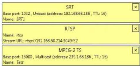
Genlock Source
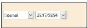
Audio Output
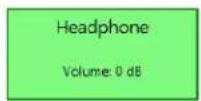
| Setting Description | |
| SRT | |
| Base port | The port number that receives the stream. |
| Name | Enter a name for your stream. |
| Network interface | Select LAN1 or LAN2. |
| Passphrase | When using encryption, this is the passphrase used to generate the encryption key. We recommend a passphrase length of 16 characters (AES-128), 24 characters (AES-192), and 32 characters (AES-256). |
| Latency | The target latency, in milliseconds (ms), for transmission. The default is 40 ms. |
| MPEG-2 TS | |
| Base port | The port number that receives the stream. |
| Name | Enter a name for your stream. |
| Network interface | Select LAN1 or LAN2. |
| Routing scheme | Select one of the following:Unicast When selecting unicast, you need to specify the destination IP address of the stream. You can enter a valid IP address or host name.Multicast Enter a Multicast address. Using multicast may require additional network configuration to support the transmission protocol (some network switches and routers can block multicast signals). For more information, contact your network administrator. |
| RTSP | |
| Name | Enter a name for your stream. |
| Network interface | Select LAN1 or LAN2 |
| RTSP URL | Enter the URL of your RTSP stream. |
| Genlock Source | |
| Internal/external | Select your genlock source, Internal or External. If you genlock to the Monarch EDGE's internal clock, you will also need to select your frame rate. |
| Audio Output (Headphone)1 | |
| Audio source | Select which audio source to output through the Monarch EDGE headphone jack. |
| Volume | Increase, decrease, or mute the headphone volume. |
- Available only when the Talkback feature is enabled.
SDI Outputs
This section describes the SDI Outputs settings for your Monarch EDGE D4 and Monarch EDGE S1 Decoding section in Monarch EDGE Control Hub.
NOTE The image below is for the Monarch EDGE D4. On a Monarch EDGE S1, you would only see a single SDI output displayed as there is only one SDI output on the device itself. However, the settings are the same for both devices.
SDI Outputs
| SDI 1SRT1Stream URL : srt//192.158.68.186/Enabled | Output settings1080p59.94YUV 4:2:2 10 bits |
| SDI 2(None)Stream URL : rtsp//Enabled | Output settings1080p59.94YUV 4:2:2 10 bits |
| SDI 3(None)Stream URL : rtsp//Enabled | Output settings1080p59.94YUV 4:2:2 10 bits |
| SDI 4(None)Stream URL : rtsp//Enabled | Output settings1080p59.94YUV 4:2:2 10 bits |
| Setting Description | |
| Enable output | Enable the selected SDI output. |
| Output stream selector | Select which of your input streams you want to assign to the selected SDI output. You must create your input streams before they are available in the drop-down list. |
| Output settings (Resolution) | Select the resolution for your SDI output. Whenever possible, try to match the resolution and frame rate of the stream sent from the encoder. This will produce the best results. |
Configuring Network settings
This section describes the Network settings in Monarch EDGE Control Hub.
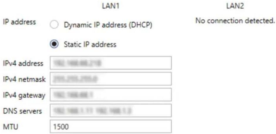
NOTE For illustration purposes, LAN2 is not connected in this example. If there were a secondary LAN connection, the same settings as LAN1 would apply.
| Setting Description | |
| IPv4 address | An IP address between 192.168.0.0 and 192.168.255.255 (recommended). Also, we recommend you assign an IP address within the subnet of your network. |
| IPv4 netmask | The subnet mask defining group of IP addresses in your subnet. By default, the subnet mask is 255.255.255.0. |
| IPv4 gateway | The gateway is often the same as your IP address, but the last byte may be 0 or 1. |
| DNS servers | The address of your DNS (Domain Name System) server or servers. If multiple addresses are entered, separate each address with a space. |
| MTU | This is the maximum transmission unit value (default is 1500) that can be transmitted without packet fragmentation. This value is typically set by a network administrator to optimize network throughput. |
Configuring Date and Time settings
This section describes the Date and Time settings in Monarch EDGE Control Hub.
| NTP server | Disabled |
| NTP server URL | time.matrox.com |
| Time zone | (UTC-5:00) Toronto |
Date and time
● Use current date and time settings of the device
○ Use date and time of the current system
○ Use the following date and time
Thursday, October 21, 2021 6:36:12 PM
○ Enable synchronization with an NTP (Network Time Protocol) server
NTP server URL time.matrox.com
○ Disable synchronization with an NTP server
Time zone
○ Use current time zone of the device
Use the following time zone
(UTC-5:00) Toronto
| Setting Description | |
| Date and time | |
| Use current date and time settings of the device | Keep the current date, time, and NTP (Network Time Protocol) synchronization settings for your devices. This is the default. |
| Use date and time of the current system | Use the date and time of your controller system to update your devices. This setting uses the time zone of the controller system. If your controller system and your device are using different time zones, the date and time will differ. This setting disables synchronization with an NTP server. |
| Use the following date and time | Use the date and time specified to update your devices. This setting doesn’t use the time zone of your controller system. You can use the arrow keys to change the date and time specified. This setting disables synchronization with an NTP server. |
| Enable synchronization with an NTP server | Use an NTP server to update the date and time for your device at regular intervals. You must provide the NTP server URL, even if one is already stored on your device. For more information on using NTP, contact your network administrator. |
| Disable synchronization with an NTP server | Stop using an NTP server to update the date and time for your device. Disabling NTP keeps the current date and time of the device, but it won’t update the devices at regular intervals. |
| Time zone | |
| Use current time zone of the device | Use the time zone currently set for your devices. This is the default. |
| Use the following time zone | Change the time zone for your devices to the one selected. Changing the time zone may adjust the date and time for a device. |
Configuring Genlock settings
This section describes the Genlock settings in Monarch EDGE Control Hub for the Monarch EDGE E4 only. For the Monarch EDGE D4 and Monarch EDGE S1 genlock settings, see "Configuring Decoder Processing settings" on page 48.
Click Enable genlock to synchronize SDI outputs to the device's internal clock. You can genlock your SDI devices/cameras to either an NTSC-based or PAL-based resolution.
Genlock

Enable genlock
Genlock resolution:
BlackBurstResolut

BlackBurstResolution_RESOLUTION_NTSC
BlackBurstResolution_RESOLUTION_PAL
Configuring DP Output settings
This section describes the DP Output settings in Monarch EDGE Control Hub.
Select Enable local preview of input/output to turn on the Monarch EDGE preview feature. You can view the video preview on a monitor connected to the Monarch EDGE DisplayPort connector. Select the Audio source and Video source(s) for your preview from the drop-down lists provided.
NOTES
- The preview feature will affect the Monarch EDGE encoding and decoding performance. If you use preview while the Monarch EDGE is streaming, you may experience performance-related issues.
- Setting RTMP streaming to a 10-bit pixel format results in a green-tinted video preview using Wowza or Adobe players. The actual streaming output is not affected, only the video preview.
Configuring Tally settings
This section describes the Tally settings in Monarch EDGE Control Hub. This includes both dedicated Tally signals and general purpose interface (GPI) inputs and outputs.
When the 15-pin Tally connector is connected to the Monarch EDGE, the Tally and GPI circuits allow you to turn on camera tally lights or trigger actions on other equipment. This feature is used with the Monarch EDGE E4, Monarch EDGE D4 and/or Monarch EDGE S1 devices working together to combine each device's encoder and decoder capabilities.
For example, signals can be sent from the production switcher to the D4 or S1 decoder input, which transfers these signals to the E4 or S1 encoder output for output to the cameras.
The Tally section in Monarch EDGE Control Hub allows you to test your Tally and GPI connections, and then pair your devices for a real Tally workflow.
NOTE The Monarch EDGE S1 can be paired with another Monarch EDGE S1, a Monarch EDGE E4, or a Monarch EDGE D4. When paired with another S1 or E4 device, four GPI inputs and outputs are usable on each device (tally connections 5, 6, 7, and 8 are not available). When paired with a D4 device, the Tally behavior works similar to the Monarch E4 to D4 behavior.
About Test Mode and Live Mode
The Monarch EDGE Tally feature provides you with two modes:
Test mode: This mode allows you to test your wiring connections against the Tally signals in the Control Hub user interface. Since the encoding and decoding pins are not directly
mappable, use the information in "Tally and GPIO circuits" on page 98 to properly wire your connector, and then use Test mode to validate your connections.
Live mode: After you have tested your connections and verified the pins are mapped correctly, you can pair your Monarch EDGE devices, then turn on Live mode to use the Tally feature.
Testing your Tally and GPI connections
The Test mode feature of the Monarch EDGE allows you to test your Tally and GPI signals with a connected device to ensure that your Tally connector pin mapping is correct. For detailed information on the connector wiring pinout, see the section "Tally and GPIO circuits" on page 98.
To use Test mode:
Step 1. Make sure your 15-pin connector has been wired according to the information in the section "Tally and GPIO circuits" on page 98.
Step 2. Connect your peripheral device to the Monarch EDGE Tally port (see "Matrox Monarch EDGE E4 and D4 rear connections" on page 7).
Example: If you are testing the E4, connect your camera tally system to the Monarch EDGE to test the tally lights.
Step 3. Select a device from the main page of Monarch EDGE Control Hub.
Step 4. From the Tally and Talkback page of Monarch EDGE Control Hub, under Tally and GPI - Inputs and Outputs, select Test mode.
Step outcome: The Output Signal toggle buttons will become active.
Step 5. Toggle one of the signals to ON.
Example: On an E4, turn on Tally 1 (Pin 4).
Step 6. Verify that the tally light on the camera (in this example) connected to pin 4 turns on.
Step 7. Continue this process to validate all your pinout connections.
Result of this task: You have successfully validated the Tally and GPI pinout connections.
Using your Tally and GPI connections
After you have validated your pinout connections, you can put the Monarch EDGE into Live mode to pair your devices. Then you can use the Tally and GPI connections in your workflow.
Step 1. From the main Monarch EDGE Control Hub page, select a Monarch EDGE to start pairing.
Step 2. In the Paired device field, type the IP address (e.g. https://192.168.123.45) of the Monarch EDGE you want to pair with, then clickPair.
Step 3. From the Tally and Talkback page of Monarch EDGE Control Hub, under Tally and GPI - Inputs and Outputs, select Live mode.
Step 4. Go to the same page for the Monarch EDGE device you just paired to, and pair back to the IP address of the Monarch EDGE in the previous step. Pairing must occur on both devices.
Step 5. Connect your peripheral devices (e.g. cameras, production switcher, etc) to the Monarch EDGE Encoder and Decoder.
Result of this task: Your devices are ready for a Tally and GPI workflow.
Configuring Talkback settings
The Talkback feature allows directional communication between two Monarch EDGE devices. This section describes the Talkback settings in Monarch EDGE Control Hub.
Step 1. On the first Monarch EDGE, select Enable the talkback functionality, then click Apply.
More info: This makes analog audio (i.e. the XLR connections) unavailable for primary streaming functions.
Talkback

Enable the talkback functionality
Outbound stream
Inbound stream
rtsp://192.168.68.229:3049/S0
rtsp://rtsp://192.168.68.185:3049/S0
Step 2. Do the same thing on your second Monarch EDGE.
Step 3. Copy the Outbound stream from the first Monarch EDGE and paste it to the Inbound stream field of the second Monarch EDGE, then click Apply.
Step 4. (Optional) Configure Advanced settings:
○ Base port - Specify your base port for Talkback if you want a different port than your stream settings.
- RTSP port - Specify your RTSP port for Talkback if you want a different port than your stream settings.
○ LAN selection - Select which of the Monarch EDGE LAN connections is used for Talkback.
Step 5. Do the same thing from the second Monarch EDGE device to the first.
More info: The outbound stream of one Monarch EDGE becomes the inbound stream of the other.
Result of this task: This allows bi-directional communication from one device to the other through the Monarch EDGE analog audio connectors.
When done, remember: You will not be able to use the XLR connection for program audio when the Talkback feature is active. If needed, you can verify if Talkback inbound and/or outbound streams are active from the main status page of Monarch EDGE Control Hub.
Managing Logs
This section describes the Logs settings in Monarch EDGE Control Hub.
- Download device logs Download the log files that contain information on your Monarch EDGE to use for troubleshooting purposes.
- Erase device logs Erase the log files.
- Download device audits This file contains information on the user interactions with your Monarch EDGE devices for troubleshooting purposes.
Logs
Download device logs
Erase device logs
Audits
Download device audits
Managing configurations
This section describes the Manage Configurations settings in Monarch EDGE Control Hub.
- Save Save your Monarch EDGE's configuration settings.
- Select Select and load a previously-saved configuration, or load the Monarch EDGE's default configuration.
- Edit Rename or delete a previously-saved configuration. You can also directly edit the settings by editing the XML in the .fav file that is exported.
- Export Export your configuration settings to your computer.
- Import Import configuration settings from your computer.
Grouping Monarch EDGE devices
From the main Monarch EDGE Control Hub page, you can group devices together into Logical groups or Sync groups.
Logical groups: These are standard groups of any number of Monarch EDGE devices. This type of grouping makes it easier to monitor your devices in the Control Hub user interface, especially when you have many devices in many different locations. You can also group devices that are paired. Other than visually, this grouping has no other effect on the devices themselves.
Sync groups: These are groups of Monarch EDGE E4 and S1 devices only, as you can only synchronize encoder-capable devices. Sync groups are not related to logical groups in any
way; that is, devices that belong to one sync group can be found in different logical groups. Sync groups share a common timestamp value to allow for synchronization of streams by decoders (SRT and MPEG-2 TS only). Devices in a Sync group will have an SG# displayed depending on how many groups you have (e.g. SG1, SG2, SG3, etc).
To group devices together, right-click any of the devices on the main page and then selected Move to group for a Logical group, or select Move to sync group to group encoders together for stream synchronization. You are able to create your groups from the right-click menu.
In the example on the right, you have both Logical groups and Sync groups.
There are two sets of devices paired for a Tally/GPI workflow. Notice that the encoders in each Logical group are also part of a Sync group.
In UK Group, devices are not part of a Sync group, but they are logically grouped by location, and two of them are offline.
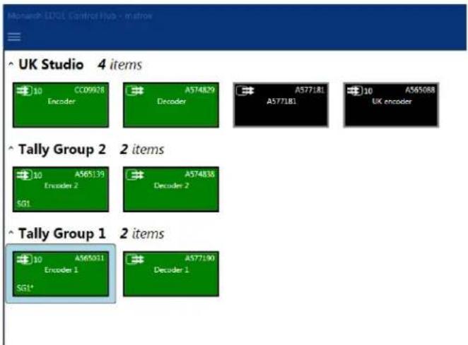
CHAPTER 7
Monarch EDGE Command Center configuration
This chapter includes the following topics:
- About Monarch EDGE Command Center
- Logging in to Monarch EDGE Command Center
- About the Monarch EDGE Command Center user interface
- Configuring Encode settings
- Configuring Decode settings
- Configuring Network settings
- Configuring Tally settings
- Configuring Talkback settings
- Configuring Genlock settings
- Configuring DP Output settings
- Configuring Date and Time settings
- Managing configurations
- Managing Logs
- Managing SyncGroups
- Configuring User management settings
About Monarch EDGE Command Center
Monarch EDGE Command Center is a web-based configuration tool that allows you to configure a single Monarch EDGE device using a web browser (Google Chrome is recommended). It includes almost all the same configuration options as Monarch EDGE Control Hub except for the following:
- You cannot remotely reboot EDGE devices.
- You cannot view all the EDGE devices on your network.
- You cannot manage users and their access to multiple devices, only the individual device you are logged on to.
The advantage of using a web-based configuration tool is that you don't have to install any software and it can be used regardless of your operating system.
Monarch EDGE Command Center is only available on Monarch EDGE devices running firmware version 2.01 or later, so you may need to update your device firmware as described in "Updating the Monarch EDGE firmware" on page 14.
Logging in to Monarch EDGE Command Center
To log in to your Monarch EDGE device's Command Center user interface, you must know the EDGE device's IP address.
If you don't know your device's IP address, and you have access to the physical EDGE device, you can see the IP address displayed on the LCD screen.
If you don't have access to the physical EDGE device, you can discover its IP address by using the Monarch EDGE Firmware Updater as described in "Updating the Monarch EDGE firmware" on page 14, or by using Monarch EDGE Control Hub (if you have it installed) as described in "About Matrox Monarch EDGE device discovery" on page 17.
When you know your device's IP address, log in to Monarch EDGE Command Center:
Step 1. Open your web browser (Google Chrome is recommended) and type your Monarch EDGE device's IP address in the address bar, then pressEnter. More info:
☐ If you enter only the IP address, Command Center will default to a non-secured HTTP connection. If you want HTTPS, you must enter the proper prefix as well (e.g. https://192.168.123.456).
○ If your browser gives you a message saying that the website is not secure, you can ignore the message and continue to the login page. It only means
that the SSL certificate is not updated. This has no effect on the performance or security of the EDGE device.
Step outcome: The login page appears.
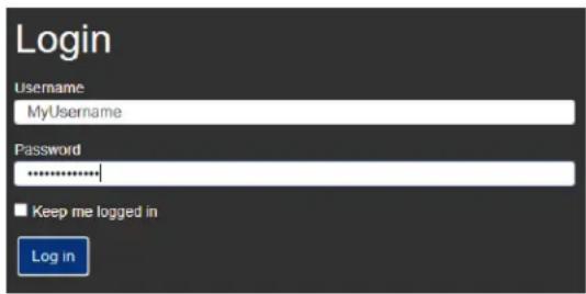
Step 2. Enter the username and password of the device, select whether or not to stay logged in, then click Log in.
More info: If this is the first time anyone has logged in to this particular EDGE device (e.g. it is a brand new device), the username and password you enter here becomes the administrator account. You will then be able to create users and assign permissions. If this EDGE has already been configured with a user account, such as from Monarch EDGE Control Hub, you must log in with the username and password that was previously assigned to it.
Result of this task: You are logged in to Monarch EDGE Command Center and can begin configuring your device as needed.
About the Monarch EDGE Command Center user interface
After you log in to your Monarch EDGE device, you will see the configuration page which consists of the following sub-sections:
Encode / Decode: These are the main settings related to video and audio streaming. Depending on which Monarch EDGE you have, you will see either Encode (Monarch EDGE E4), Decode (Monarch EDGE D4), or both (Monarch EDGE S1). For more information, see "Configuring Encode settings" on page 65, and "Configuring Decode settings" on page 79.
Network: These are the network settings that allow you to set DHCP or static IP addressing for LAN 1 and/or LAN 2 (if applicable). For more information, see "Configuring Network settings" on page 82.
Tally and Talkback: This is where you enable and use the Tally and Talkback functionality of the Monarch EDGE For more information, see "Configuring Tally settings" on page 83 and "Configuring Talkback settings" on page 85.
Genlock: This is where you enable the genlock functionality for the Monarch EDGE E4 and set the genlock output to sync to NTSC or PAL frame rates. For more information, see
"Configuring Genlock settings" on page 86. The Monarch EDGE D4 and Monarch EDGE S1 genlock settings are described in "Configuring Decode settings" on page 79.
DP Output: This is where you can enable the video preview option that uses the Monarch EDGE's DisplayPort connection. Please note that this feature can affect the EDGE's processing performance. It is not recommended to use a 4K monitor for preview. For more information, see "Configuring DP Output settings" on page 86.
Date and time: These are the settings that allow you to configure time-related options such as specifying an NTP server, or setting the time zone of your Monarch EDGE. For more information, see "Configuring Date and Time settings" on page 87.
Configuration: This where you manage different configuration settings for your EDGE device. You can create preset configuration profiles that you can load to quickly configure other EDGE devices. For more information, see "Managing configurations" on page 88.
Logs: This where you can download the logs to be used for troubleshooting your Monarch EDGE, if needed. For more information, see "Managing Logs" on page 88.
SyncGroup: This is where you create a group of EDGE devices that synchronize streaming across the entire group. For more information, see "Managing SyncGroups" on page 89.
User management: This is where you add new users and grant them different permissions. This is a simplified version of the user management functionality on Monarch EDGE Control Hub. For more information, see "Configuring User management settings" on page 89
Log out: Log out of Monarch EDGE Command Center.
Status: Verify the status of your Monarch EDGE at a glance.
Using the contextual menu for encoder and decoder settings
The Encode and Decode sections of the Monarch EDGE Command Center user interface allow you to configure your settings in a single window by using a contextual menu that changes depending on where you click.
In the following image, if you click on any of the areas indicated, the menu on the right of the Monarch EDGE Command Center window will change to display the relevant settings. The active area of Command Center will have a blue border (e.g. in the image, SDI 1 is selected).
The image below shows the encoder settings for a Monarch EDGE E4, but the user interface works the same way for Monarch EDGE D4 and Monarch EDGE S1; that is, as a menu that dynamically displays the relevant configuration settings depending on where you click.
This image does not necessarily represent a realistic user scenario, it is intended simply to show you where in the user interface you can click to access the desired settings.
Monarch EDGE E4

Click a box to configure your Inputs/Output settings
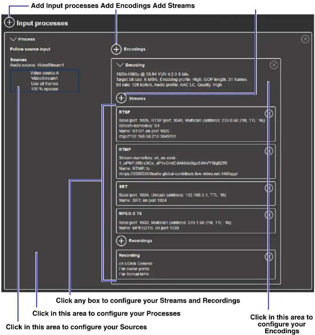
Clicking any of the above areas shows the settings in the contextual menu, as follows.
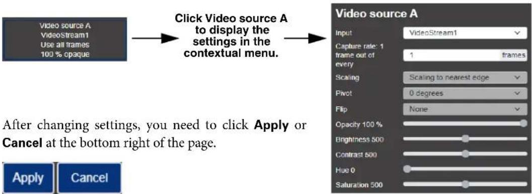
flowchart
graph LR
    A["Video source A\nVideoStream1\nUse all frames\n100 % opaque"] --> B["Click Video source A to display the settings in the contextual menu."]
    B --> C["After changing settings, you need to click Apply or Cancel at the bottom right of the page."]
Configuring Encode settings
This section describes the Monarch EDGE Command Center Encode settings for your Monarch EDGE E4 and Monarch EDGE S1.
Inputs/Output
This section describes the Inputs/Output settings in Monarch EDGE Command Center.
Monarch EDGE E4 settings

Monarch EDGE S1 settings

| Connector Setting Description | ||
| SDI Inputs 1 to 4 (Monarch EDGE E4) ^1 SDI Input 1 (Monarch EDGE S1) | Enable input | Enable the input. Monarch EDGE detects the input resolution but you still need to enable the input. Monarch EDGE will not stream unless there is an input connected to it. |
| Input name | Give the input a specific name. | |
| Analog Audio Input ^2 | Enable input | Enable your XLR analog audio input. |
| Gain | Increase or decrease the amplitude of your analog audio input. | |
| Headphone | Audio source | Select which audio source to output through the Monarch EDGE headphone jack. |
| Volume | Increase, decrease, or mute the headphone volume. | |
- The audio value shown here is what the SDI input is feeding to the Monarch EDGE's codec. For example, even if your video contains 24-bit audio, the AAC codec can only handle 16-bit so that is what is displayed.
- Available only when the Talkback feature is disabled.
Input processes
This section describes the Input processes settings in Monarch EDGE Command Center.
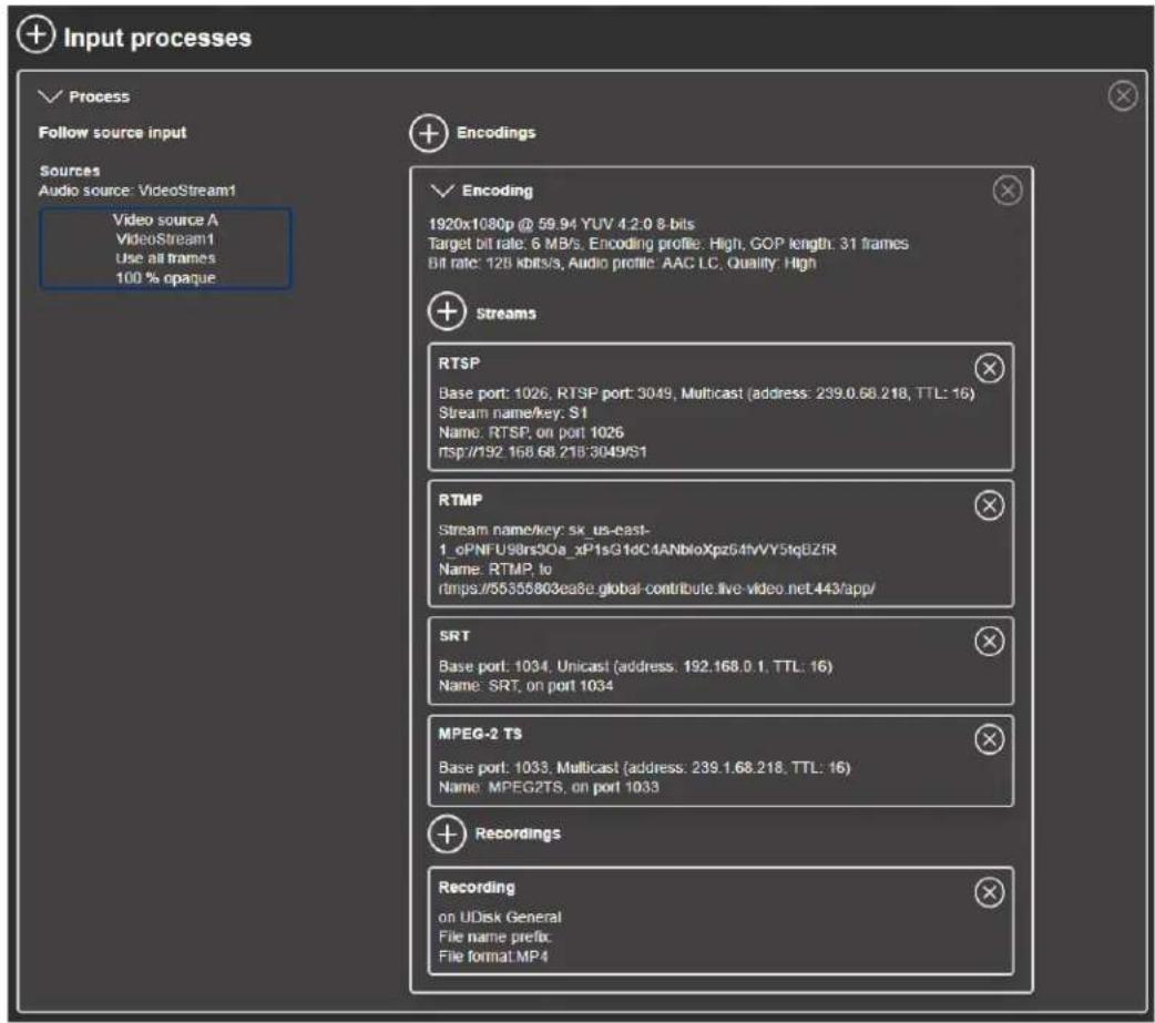
| Setting Description | |
| Audio | |
| Audio source | The source of the audio signal to use. |
| Video | |
| Layout | Select the video layout and the number of sources to use. |
| Follow source input | By default, Monarch EDGE will follow the frame size, frame rate, background color, and pixel format of the source video. If you want to customize these settings, clear this option and the settings become available for modification. For interlaced signals, you must select this option for the interlaced nature of the signal to be preserved in the encoding process. |
| Frame size | The width and height, in pixels, of the source. If the layout of your sources uses a height or width that's smaller than your frame size, black borders may appear on both sides, or on the top and bottom, of the frame. The width ranges from 64 to 4096 and must be a multiple of 16. The height ranges from 64 to 4096 and must be an even number. |
| Frame rate | The frame rate, in FPS (frames per second), for the source. |
| Background color | The background color for your source. If the layout of your sources uses less height or width than your frame size, the borders will use the background color. If no video is captured for your source, the background color is shown instead. |
| Pixel format | The pixel format to define the quality of your image, and the pixel depth for each color in the image format. A higher YUV format and pixel depth provides a higher quality image and requires more resources to process. Only certain pixel formats may be available. |
| Video sources | |
| Input | Select the input to use for your source. |
| Capture rate | Select the rate of capture per input. |
| Scaling | Select how to scale your video:Unscaled from top left The video is unscaled and positioned in the top left corner of the display area. If the display resolution of the video is bigger than the display area, the video will be cropped.Unscaled centered The video is unscaled and centered in the display area. If the display resolution of the video is bigger than the display area, the video will be cropped.Stretched to all edges The video is stretched to fit the entire display area without respecting the aspect ratio of the original video. If the aspect ratio of the video and the display area don't match, the video may be distorted.Scaled to all edges The video is scaled to fit the entire display area while respecting the aspect ratio of the original video. The video is centered in the display area. If the aspect ratio of the video and the display area don't match, the video will be cropped.Scaled to nearest edge The video is scaled to fit to the display area while respecting the aspect ratio of the original video. The video is centered in the display area. If the aspect ratio of the video is not scaled to the display area, black borders will appear on both sides of the video or above and below. The video isn't cropped. |
| Setting Description | |
| Pivot | Change the orientation of your source:0 degrees No pivot is applied.90 degrees clockwise The source is rotated 90 degrees clockwise.180 degrees The source is rotated 180 degrees.90 degrees counterclockwise The source is rotated 90 degrees counterclockwise. |
| Flip | Select the plane along which the source is flipped:None No flip is applied.Vertically The source is flipped along the vertical plane. The top becomes the bottom.Horizontally The source is flipped along the horizontal plane. The right side becomes the left.On both axes The source is flipped along the vertical plane and the horizontal plane. This is visually similar to rotating 180 degrees. |
| Opacity | Increase or decrease how opaque the source video appears. The default is 100%. |
| Brightness | Increase or decrease how light or dark the colors appear. The default is 500. |
| Contrast | Change the difference in brightness between the lightest and darkest colors. The default is 500. |
| Hue | Increase or decrease the tint or tone of colors. The default is 0. |
| Saturation | Increase or decrease the depth of the colors. The default is 500. |
Encodings
This section describes the Encoding settings in Monarch EDGE Command Center.
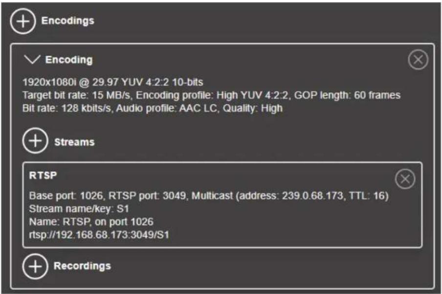
NOTE One RTSP stream is active by default when you create a new Encoding. For more information, see "Streams" on page 73.
| Setting Description | |
| Include | Select the signals to include (Audio only, Video only, or Audio and video) in your encoding. |
| Video | |
| Force encoding size | Select to increase or reduce the captured video size before encoding. |
| Frame size | Specify the width and height, in pixels, of the video up to the width and height of the original video layout. If your canvas uses a different size, your encoder scales the video to the specified size (image may be distorted). The width ranges from 64 to 3840 and must be a multiple of 16. The height ranges from 64 to 2160 and must be an even number. |
| Setting Description | |
| Scaling | Select how to scale your video:Unscaled from top left The video is unscaled and positioned in the top left corner of the display area. If the display resolution of the video is bigger than the display area, the video will be cropped.Unscaled centered The video is unscaled and centered in the display area. If the display resolution of the video is bigger than the display area, the video will be cropped.Stretched to all edges The video is stretched to fit the entire display area without respecting the aspect ratio of the original video. If the aspect ratio of the video and the display area don't match, the video may be distorted.Scaled to all edges The video is scaled to fit the entire display area while respecting the aspect ratio of the original video. The video is centered in the display area. If the aspect ratio of the video and the display area don't match, the video will be cropped.Scaled to nearest edge The video is scaled to fit to the display area while respecting the aspect ratio of the original video. The video is centered in the display area. If the aspect ratio of the video is not scaled to the display area, black borders will appear on both sides of the video or above and below. The video isn't cropped. |
| Pivot | Change the orientation of your source:0 degrees No pivot is applied.90 degrees clockwise The source is rotated 90 degrees clockwise.180 degrees The source is rotated 180 degrees.90 degrees counterclockwise The source is rotated 90 degrees counterclockwise. |
| Flip | Select the plane along which the source is flipped:None No flip is applied.Vertically The source is flipped along the vertical plane. The top becomes the bottom.Horizontally The source is flipped along the horizontal plane. The right side becomes the left.On both axes The source is flipped along the vertical plane and the horizontal plane. This is visually similar to rotating 180 degrees. |
| Force pixel format | The pixel format defines the quality of the image encoded. YUV refers to the color format used to receive each block of bits in the video signal. The format is followed by the pixel depth used for each color in the image format. A higher YUV format and pixel depth provides a higher quality image and requires more resources to process. |
| Encoding profile^1 | Select an encoding profile for your signal. Changing the encoding profile may prevent your decoder from streaming.BaselineMainHighHigh 10-bit (if available)High YUV 4:2:2 (if available) |
| Target bit rate | The target bit rate, in Mb/s (Megabits per second), for encoding. The actual bandwidth used by your encoder varies according to your source and encoding method. The default is 15 Mb/s. A lower target bit rate may result in lower image quality. A higher target bit rate limit may result in lower performance or may require higher network bandwidth. |
| Bit rate control | Select one of the following:Use variable bit rateUse constant bit rate |
| Maximum bit rate | The maximum bit rate for variable bit rate encoding. When encoding, the processor attempts to use the target bit rate but may use up to the maximum bit rate specified here.The default is 22.5 Mb/s. The maximum bit rate you can set is 120 Mb/s. |
| Quantization parameters | The range used to compress the various frames in your GOP. A high maximum increases the level of compression of the frame and should decrease the bit rate but may decrease the image quality. |
| Encoding mode | Select one of the following:Optimized for low latency^2 Potentially reduces the delay between the time the video is captured on the encoder and the time it's shown on a monitor connected to a decoder (not supported on third-party decoders).Favor image quality^3 Favors image quality over latency, but may introduce extra frames of delay in certain circumstances. Matrox highly recommends this setting when using default encoding parameters. |
| Force CAVLC entropy encoding | Enable this to force the use of context adaptive variable length coding (CAVLC) entropy encoding. Enabling this option over- rides the default entropy encoding selection (CABAC). |
| GOP length | The number of frames from one complete frame (I-frame) to another. A higher GOP length increases the compression level but may result in a lower quality image.The default GOP length is 30. |
| Insert P-frame every | Enter the number of frames before a P-frame is inserted. All other frames are B-frames. A higher number of frames before inserting a P-frame increases the quality of the image but may result in a loss of performance.The minimum and default value is 1 (indicating no B frames^4 ). The maximum value is 4. |
| Audio | |
| Bit rate | Select the audio bit rate, in kbps, for your audio transmission. A higher bit rate produces a sound quality closer to the source qual- ity but requires more bandwidth.The value ranges from 32 to 576. The default is 128. |
| AAC encoder | Select one of the following:·AAC LC Allowed bit rate range is 32 to 576 kbps.·AAC HEv1 Allowed bit rate range is 32 to 288 kbps.·AAC HEv2 Allowed bit rate range is 32 to 144 kbps. |
| AAC quality | Force the use of encoding complexity (low to high) to improve the quality of compressed audio. Adjusting these settings doesn't affect the audio sample rate, target bit rate, or latency.LowMediumHigh |
| Use temporal noise shaping | This reshapes the quantization noise over time to improve the quality of the audio signal. This option is enabled by default. |
| AAC format | Select one of the following:·ADTS·No container format |
-
The encoding profile you want may not be available depending on the pixel format of your video.
-
Low latency cannot be maintained if you change the Monarch EDGE Encoder settings while streaming to the Monarch EDGE Decoder. To re-establish low latency, go to your Monarch EDGE Decoder's SDI Output settings, disable the output, set Output stream selector to None, then click Apply. After you have disabled the output and the stream, re-enable both of them to ensure low latency is restored to your stream.
- The Optimized for low latency mode does not necessarily result in improved latency, as you may have the same latency performance as the Favor image quality mode. However, the Favor image quality mode will always result in a better quality image and is recommended unless specific encoder uses cases are validated.
- There are no B frames in low latency mode.
Streams
This section describes the Streams settings in Monarch EDGE Command Center.
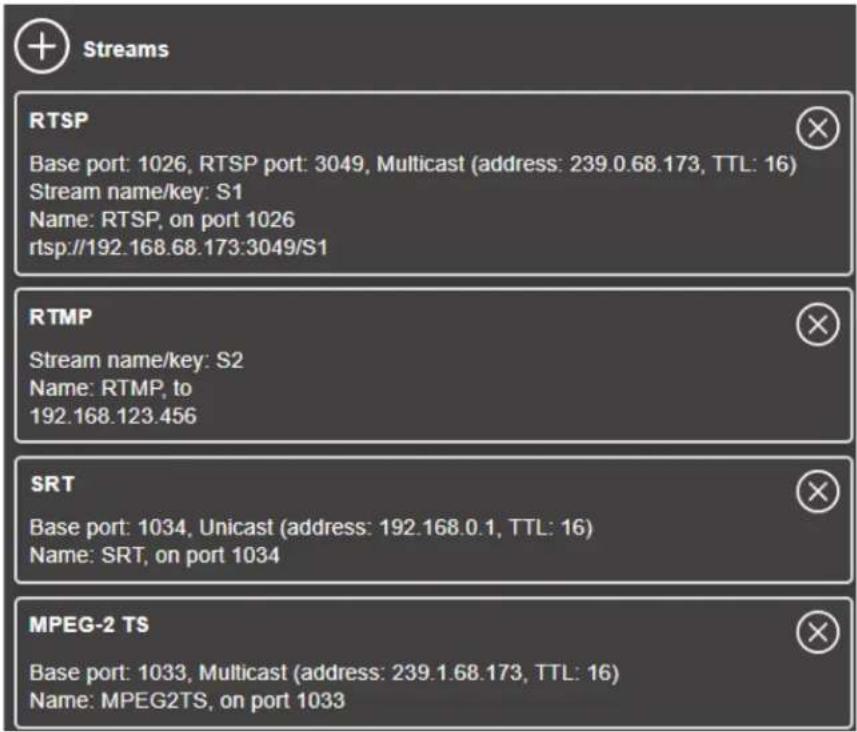
| Setting Description | |
| RTSP | |
| Enable stream | Enable or disable your stream. |
| Audio pair selection | Select the audio pair you want to encode. You can select one pair per stream, but you can create additional streams and select a different audio pair for each of them (e.g. use the same stream but with a different language for each other audio pair). |
| Base port | The port number used to transmit your stream. |
| Name | Enter a name for your stream. |
| Network interface | Select LAN1 or LAN2 |
| RTSP port | The RTSP port number used to transmit your stream. |
| Stream name/key | Enter a suffix as part of your stream address. If you're using a media player to decode your stream, the media player may require this as part of the stream address to connect to a stream. |
| Time to live | The number of hops or network nodes (such as network switches or routers) through which a multicast signal can travel. Once the TTL number is reached, the receiving network node prevents the signal broadcast further down the network. The value ranges from 1 to 255. The default is 16. |
| Routing scheme | Select one of the following:·Unicast When selecting unicast, you need to specify the destination IP address of the stream. You can enter a valid IP address or host name.·Multicast Enter a Multicast address. Using multicast may require additional network configuration to support the transmission protocol (some network switches and routers can block multicast signals). For more information, contact your network administrator. To also allow unicast connections, enable the Allow unicast connec-tions option. |
| RTMP | |
| Enable stream | Enable or disable your stream. |
| Audio pair selection | Select the audio pair you want to encode. You can select one pair per stream, but you can create additional streams and select a dif-ferent audio pair for each of them (e.g. use the same stream but with a different language for each other audio pair). |
| Push location | The path of your RTMP stream. |
| Name | Enter a name for your stream. |
| Network interface | Select LAN1 or LAN2 |
| Stream name/key | Enter a suffix as part of your stream address. If you're using a media player to decode your stream, the media player may require this as part of the stream address to connect to a stream. |
| Use authentication | Enable this if you're using an authentication server, then enter your credentials (User name and Password). |
| MPEG-2 TS | |
| Enable stream | Enable or disable your stream. |
| Audio pair selection | Select the audio pairs you want to encode. You can select up to four pairs (i.e. eight audio channels) per stream, but you can create additional streams and select different audio pairs for each of them.NOTE The embedded audio channel mapping from Monarch EDGE Encoder to Decoder will match, regardless of which audio channels you select. For example, if you select audio pairs 1-2 and 13-14 on the encoder side, they will be mapped to the same loc tions on the decoder side. The other audio channels will be blank. |
| Base port | The port you are transmitting to on the receiving device. |
| Name | Enter a name for your stream. |
| Network interface | Select LAN1 or LAN2 |
| Time to live | The number of hops or network nodes (such as network switches or routers) through which a multicast signal can travel. Once the TTL number is reached, the receiving network node prevents the signal broadcast further down the network. The value ranges from 1 to 255. The default is 16. |
| Routing scheme | Select one of the following:· Multicast Enter a Multicast address. Using multicast may require additional network configuration to support the transmission protocol (some network switches and routers can block multicast signals). For more information, contact your network administrator. To also allow unicast connections, enable the Allow unicast connec-tions option.· Unicast When selecting unicast, you need to specify the destination IP address of the stream. You can enter a valid IP address or host name. |
| SRT ^1 | |
| Enable stream | Enables the SRT stream to the specified location. |
| Setting Description | |
| Audio pair selection | Select the audio pairs you want to encode. You can select up to four pairs (i.e. eight audio channels) per stream, but you can create additional streams and select different audio pairs for each of them.NOTE The embedded audio channel mapping from Monarch EDGE Encoder to Decoder will match, regardless of which audio channels you select. For example, if you select audio pairs 1-2 and 13-14 on the encoder side, they will be mapped to the same loc tions on the decoder side. The other audio channels will be blank. |
| SRT Protocol | Set your SRT protocol to Caller, Listener, or Rendezvous.Caller: The device must know the public IP address and port number of the Listener-modener: The device only needs to know that it should listen for an SRT stream on a certain port.Rendezvous: Allows two devices to negotiate an SRT session over a mutually agreed upon port. Both source and destination must be in Rendezvous mode. |
| Base port | The port you are transmitting to on the receiving device. |
| Name | Enter a name for your stream. |
| Network interface | Select LAN1 or LAN2 |
| Encryption | Select one of the following:UnencryptedAES-128AES-192AES-256 |
| Passphrase | When using encryption, this is the passphrase used to generate the encryption key. We recommend a passphrase length of 16 characters (AES-128), 24 characters (AES-192), and 32 characters (AES-256). |
| Latency | The target latency, in milliseconds (ms), for transmission. The default is 40 ms. |
| Time to live | The number of hops or network nodes (such as network switches or routers) through which a multicast signal can travel. Once the TTL number is reached, the receiving network node prevents the signal broadcast further down the network. The value ranges from 1 to 255. The default is 16. |
| Routing scheme | Only unicast is available. You must specify a unicast address. You can enter a valid IP address or host name. The SRT protocol prefix (srt://) and the base port suffix (:9000) aren't required when entering a host name as the unicast address. |
- When using the SRT streaming protocol, you may experience a few frames of misaligned video when attempting to decode four streams. However, this misaligned video may not be visibly noticeable.
Recordings
This section describes the Recordings settings in Monarch EDGE Command Center.
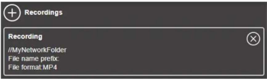
| Setting Description | |
| Enable recording | Enable or disable your recording. IfScheduled recordingis enabled, this option isn’t available. |
| File name prefix | The video file name is made up of two parts:First part- The name, which you enter.Second part- The timestamp of when the video file started, which your encoder defines.The resulting file name isPrefix[YYYY-MM-DD_HH-MM-SS].mp4, where YYYY is the year, MM the month, DD the day, HH the hour (in a 24-hour format), MM the minutes, and SS the seconds. A file name prefix can be up to 19 characters long. |
| File format | Select the format for your recording (MP4 or MOV). To use fragmented MP4, enable theUse MP4 file fragmentationoption.This option ensures your recorded file won’t be corrupted in the event your network connection is disrupted. |
| Maximum file block duration | Enter the recording time for each video file recorded. Once the recording time for a file is reached, Monarch EDGE creates a new file. A file can hold up to 8 hours of recording. If the sampling rate (audio or video) changes, a new file is created, regardless of the file duration. |
| Record to | Under Record to, provide the path to the existing network shared folder or select the external storage device where your video files will be stored.NOTE To make sure the network path is properly recognized by your device, we recommend you provide the full computer name or the IP address of the system where the shared folder is located. The full computer name is part of the Windows properties of the system. For example, the full computer name of network-server may be networkserver.domain.com. For more information, contact your network administrator.To safely remove an external storage device from your system, select the device you want to remove, then click theEject(△) b ton. |
| Add network shared folder | Enter the path to the existing network shared folder, then select how to connect to the shared folder:Connect as guest- If your network drive doesn't require user identification, use this. When you're done, clickOK.Connect with credentials- If your network drive requires user identification, enter a User name and Password. When you're done, click OK. |
| Manage network shared folders | Use this to review your list of credentials, and to remove user names and passwords that are no longer required. |
| Scheduled recording | Enable this to schedule a date, time, and duration for your encoder to record a video file.Start recording at- Enter the date and time to start recording.Stop recording at- Enter the date and time to stop recording. |
Configuring Decode settings
This section describes the Monarch EDGE Command Center Decode settings for your Monarch EDGE D4 and Monarch EDGE S1.
Input streams
This section describes the Input Streams settings for your Monarch EDGE D4 and Monarch EDGE S1 Decode section in Monarch EDGE Command Center.
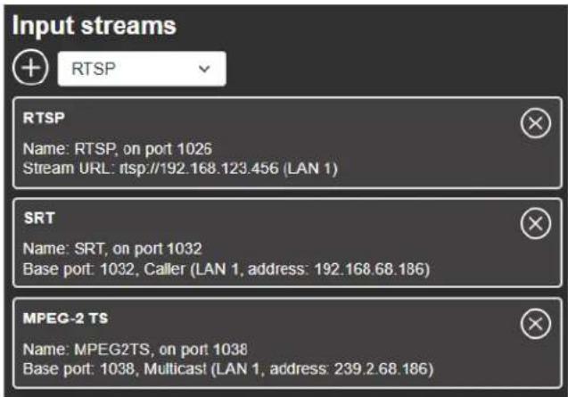
| Setting Description | |
| RTSP | |
| Name | Enter a name for your stream. |
| Network interface | Select LAN1 or LAN2 |
| RTSP URL | Enter the URL of your RTSP stream. |
| SRT | |
| Base port | The port number that receives the stream. |
| Name | Enter a name for your stream. |
| Network interface | Select LAN1 or LAN2. |
| Passphrase | When using encryption, this is the passphrase used to generate the encryption key. We recommend a passphrase length of 16 characters (AES-128), 24 characters (AES-192), and 32 characters (AES-256). |
| Latency | The target latency, in milliseconds (ms), for transmission. The default is 40 ms. |
| MPEG-2 TS | |
| Base port | The port number that receives the stream. |
| Name | Enter a name for your stream. |
| Network interface | Select LAN1 or LAN2. |
| Routing scheme | Select one of the following:Unicast When selecting unicast, you need to specify the destination IP address of the stream. You can enter a valid IP address or host name.Multicast Enter a Multicast address. Using multicast may require additional network configuration to support the transmission protocol (some network switches and routers can block multicast signals). For more information, contact your network administrator. |
Genlock
This section describes the Genlock settings for your Monarch EDGE D4 and Monarch EDGE S1 Decode section in Monarch EDGE Command Center.
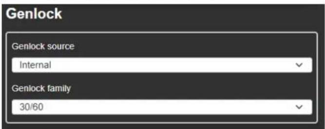
| Setting Description | |
| Genlock source | Select your genlock source, Internal or External. |
| Genlock family | If you genlock to the Monarch EDGE’s internal clock, you will need to select your frame rate family. |
Audio Output
This section describes the Audio Output settings for your Monarch EDGE D4 and Monarch EDGE S1 Decode section in Monarch EDGE Command Center.
NOTE This section only appears when the Talkback feature is enabled.

| Setting Description | |
| Audio source | Select which audio source to output through the Monarch EDGE headphone jack. |
| Volume | Increase, decrease, or mute the headphone volume. |
Configuring Network settings
This section describes the Network settings in Monarch EDGE Command Center.
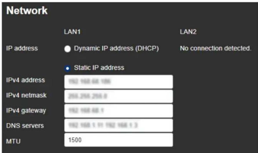
NOTE For illustration purposes, LAN2 is not connected in this example. If there were a secondary LAN connection, the same settings as LAN1 would apply.
| Setting Description | |
| IPv4 address | An IP address between 192.168.0.0 and 192.168.255.255 (recommended). Also, we recommend you assign an IP address within the subnet of your network. |
| IPv4 netmask | The subnet mask defining group of IP addresses in your subnet. By default, the subnet mask is 255.255.255.0. |
| IPv4 gateway | The gateway is often the same as your IP address, but the last byte may be 0 or 1. |
| DNS servers | The address of your DNS (Domain Name System) server or servers. If multiple addresses are entered, separate each address with a space. |
| MTU | This is the maximum transmission unit value (default is 1500) that can be transmitted without packet fragmentation. This value is typically set by a network administrator to optimize network throughput. |
Configuring Tally settings
This section describes the Tally settings in Monarch EDGE Command Center. This includes both dedicated Tally signals and general purpose interface (GPI) inputs and outputs.
When the 15-pin Tally connector is connected to the Monarch EDGE, the Tally and GPI circuits allow you to turn on camera tally lights or trigger actions on other equipment. This feature is used with the Monarch EDGE E4, Monarch EDGE D4 and/or Monarch EDGE S1 devices working together to combine each device's encoder and decoder capabilities.
For example, signals can be sent from the production switcher to the D4 or S1 decoder input, which transfers these signals to the E4 or S1 encoder output for output to the cameras.
The Tally section in Monarch EDGE Command Center allows you to test your Tally and GPI connections, and then pair your devices for a real Tally workflow.
NOTE The Monarch EDGE S1 can be paired with another Monarch EDGE S1, a Monarch EDGE E4, or a Monarch EDGE D4. When paired with another S1 or E4 device, four GPI inputs and outputs are usable on each device (tally connections 5, 6, 7, and 8 are not available). When paired with a D4 device, the Tally behavior works similar to the Monarch E4 to D4 behavior.
About Test Mode and Live Mode
The Monarch EDGE Tally feature provides you with two modes:
Test mode: This mode allows you to test your wiring connections against the Tally signals in the Command Center user interface. Since the encoding and decoding pins are not directly mappable, use the information in "Tally and GPIO circuits" on page 98 to properly wire your connector, and then use Test mode to validate your connections.
Live mode: After you have tested your connections and verified the pins are mapped correctly, you can pair your Monarch EDGE devices, then turn on Live mode to use the Tally feature.
Testing your Tally and GPI connections
The Test mode feature of the Monarch EDGE allows you to test your Tally and GPI signals with a connected device to ensure that your Tally connector pin mapping is correct. For detailed
information on the connector wiring pinout, see the section "Tally and GPIO circuits" on page 98.
To use Test mode:
Step 1. Make sure your 15-pin connector has been wired according to the information in the section "Tally and GPIO circuits" on page 98.
Step 2. Connect your peripheral device to the Monarch EDGE Tally port (see "Matrox Monarch EDGE E4 and D4 rear connections" on page 7). Example: If you are testing the E4, connect your camera tally system to the Monarch EDGE to test the tally lights.
Step 3. From the Tally and Talkback page of Monarch EDGE Command Center, under Tally and GPI - Inputs and Outputs, select Test mode.
Step outcome: The Output Signal toggle buttons will become active.
Step 4. Toggle one of the signals to ON.
Example: On an E4, turn on Tally 1 (Pin 4).
Step 5. Verify that the tally light on the camera (in this example) connected to pin 4 turns on.
Step 6. Continue this process to validate all your pinout connections.
Result of this task: You have successfully validated the Tally and GPI pinout connections.
Using your Tally and GPI connections
After you have validated your pinout connections, you can put the Monarch EDGE into Live mode to pair your devices. Then you can use the Tally and GPI connections in your workflow.
Step 1. In the Paired device field, type the IP address (e.g. https://192.168.123.45) of the Monarch EDGE you want to pair with, then clickPair.
Step 2. From the Tally and Talkback page of Monarch EDGE Command Center, under Tally and GPI - Inputs and Outputs, select Live mode.
Step 3. Go to the same page for the Monarch EDGE device you just paired to, and pair back to the IP address of the Monarch EDGE in the previous step. Pairing must occur on both devices.
Step 4. Connect your peripheral devices (e.g. cameras, production switcher, etc) to the Monarch EDGE Encoder and Decoder.
Result of this task: Your devices are ready for a Tally and GPI workflow.
Configuring Talkback settings
The Talkback feature allows directional communication between two Monarch EDGE devices. This section describes the Talkback settings in Monarch EDGE Command Center.
Step 1. On the first Monarch EDGE, turn on
Talkback, then click Apply.
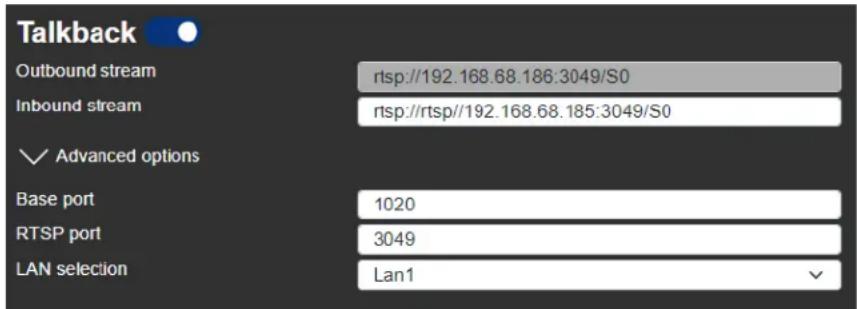
More info: This makes analog audio (i.e. the XLR connections) unavailable for primary streaming functions.
Step 2. Do the same thing on your second Monarch EDGE.
Step 3. Copy the Outbound stream from the first Monarch EDGE and paste it to the Inbound stream field of the second Monarch EDGE, then click Apply.
Step 4. (Optional) Configure Advanced settings:
○ Base port - Specify your base port for Talkback if you want a different port than your stream settings.
- RTSP port - Specify your RTSP port for Talkback if you want a different port than your stream settings.
○ LAN selection - Select which of the Monarch EDGE LAN connections is used for Talkback.
Step 5. Do the same thing from the second Monarch EDGE device to the first.
More info: The outbound stream of one Monarch EDGE becomes the inbound stream of the other.
Result of this task: This allows bi-directional communication from one device to the other through the Monarch EDGE analog audio connectors.
When done, remember: You will not be able to use the XLR connection for program audio when the Talkback feature is active. If needed, you can verify if Talkback inbound and/or outbound streams are active from the main status page of Monarch EDGE Command Center.
Configuring Genlock settings
This section describes the Genlock settings in Monarch EDGE Command Center for the Monarch EDGE E4 only. For the Monarch EDGE D4 and Monarch EDGE S1 genlock settings, see "Configuring Decode settings" on page 79.
Toggle the Genlock on to synchronize SDI outputs to the device's internal clock. You can gen-lock your SDI devices/cameras to either an NTSC-based or PAL-based resolution.
Configuring DP Output settings
This section describes the DP Output settings in Monarch EDGE Command Center.
Turn on DisplayPort output to turn on the Monarch EDGE preview feature. You can view the video preview on a monitor connected to the Monarch EDGE DisplayPort connector. Select the Audio source and Video source(s) for your preview from the drop-down lists provided.
NOTES
- The preview feature will affect the Monarch EDGE encoding and decoding performance. If you use preview while the Monarch EDGE is streaming, you may experience performance-related issues.
- Setting RTMP streaming to a 10-bit pixel format results in a green-tinted video preview using Wowza or Adobe players. The actual streaming output is not affected, only the video preview.
Configuring Date and Time settings
This section describes the Date and Time settings in Monarch EDGE Command Center.
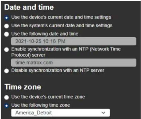
| Setting Description | |
| Date and time | |
| Use current date and time settings of the device | Keep the current date, time, and NTP (Network Time Protocol) synchronization settings for your devices. This is the default. |
| Use date and time of the current system | Use the date and time of your controller system to update your devices. This setting uses the time zone of the controller system. If your controller system and your device are using different time zones, the date and time will differ. This setting disables synchronization with an NTP server. |
| Use the following date and time | Use the date and time specified to update your devices. This setting doesn’t use the time zone of your controller system. You can use the arrow keys to change the date and time specified. This setting disables synchronization with an NTP server. |
| Enable synchronization with an NTP server | Use an NTP server to update the date and time for your device at regular intervals. You must provide the NTP server URL, even if one is already stored on your device. For more information on using NTP, contact your network administrator. |
| Disable synchronization with an NTP server | Stop using an NTP server to update the date and time for your device. Disabling NTP keeps the current date and time of the device, but it won’t update the devices at regular intervals. |
| Time zone | |
| Use current time zone of the device | Use the time zone currently set for your devices. This is the default. |
| Use the following time zone | Change the time zone for your devices to the one selected. Changing the time zone may adjust the date and time for a device. |
Managing configurations
This section describes the Configurations settings in Monarch EDGE Command Center.
- Import Import configuration settings from your computer.
• Export Export your configuration settings to your computer. - Save Save your Monarch EDGE's configuration settings.
- Edit Rename or delete a previously-saved configuration. You can also directly edit the settings by editing the XML in the .fav file that is exported.
- Select Select and load a previously-saved configuration, or load the Monarch EDGE's default configuration.
Managing Logs
This section describes the Logs settings in Monarch EDGE Control Hub.
- Download device logs Download the log files that contain information on your Monarch EDGE to use for troubleshooting purposes.
- Erase device logs Erase the log files.
- Download device audits This file contains information on the user interactions with your Monarch EDGE devices for troubleshooting purposes.
Managing SyncGroups
This section describes the SyncGroups settings in Monarch EDGE Command Center.
Sync groups are groups of Monarch EDGE E4 and S1 devices only, as you can only synchronize encoder-capable devices. Sync groups share a common timestamp value to allow for synchronization of streams by decoders (SRT and MPEG-2 TS only). Devices in a Sync group will have an SG# displayed depending on how many groups you have (e.g. SG1, SG2, SG3, etc).
To group devices together, you must set up your device as either a primary or secondary device:
Step 1. From the SyncGroups section of Monarch EDGE Command Center, turn onSyncGroups.
Step 2. Set up this Monarch EDGE as a primary or secondary device:
a. If you are setting up this EDGE device as a primary device, click Primary device, then enter your Group name.
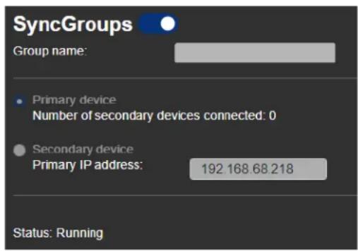
b. If you are setting up this EDGE device as a secondary device, click Secondary device, then enter the IP address of the primary EDGE device you want to synchronize to.
Step 3. Continue adding other EDGE devices to your SyncGroup as needed.
Result of this task: Your secondary devices are synchronized to the primary device, and streams will start and end in sync.
Configuring User management settings
This section describes the User management settings in Monarch EDGE Command Center.
User management in Monarch EDGE Command Center is a simplified version of user management in Monarch EDGE Control Hub. The difference being that you can configure users on a
single device, and that device inherits any settings that have already been configured in Control Hub.
Also, if you are using your Monarch EDGE for the first time, the username and password you log in with becomes the administrator account for that device. This is the equivalent of taking control of the device as described in the Control Hub user management chapter (see "User and device management" on page 21).
To configure users, follow the steps below:
Step 1. Go to the
User management section in Monarch EDGE Command Center.
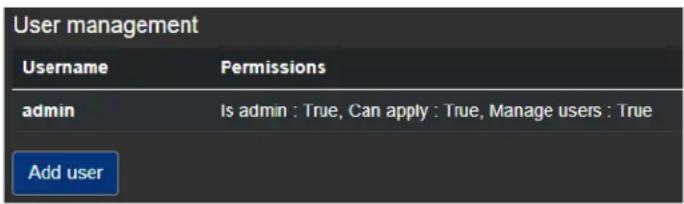
More info: You will see all the users that have permissions on this device. In this example, the only user is the admin user that was created when you initially logged in to this particular EDGE. The Permissions are shown.
Step 2. To add a new user, click
Add user.
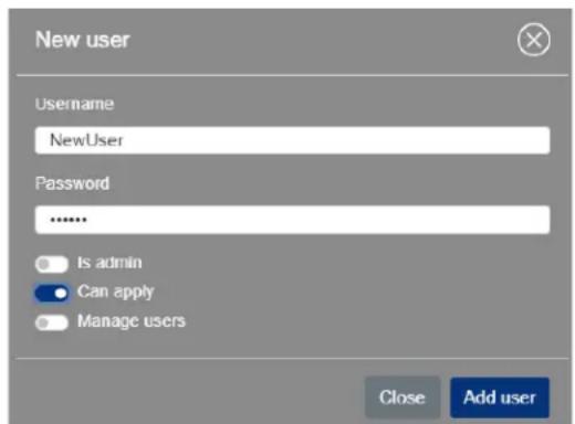
The Add user window appears.
Step 3. Type the
Username and Password for the user you want to add, then specify missions:
- Is admin Gives the new user the same administrator rights as you have, including the two other permissions below.
- Can apply Allows the user to change and apply settings.
○ Manage users Allows the user to manage their own account and manage other users. This permission does not allow the user to create new users, only manage existing ones.
Step 4. Click Add user.
Step 5. (Optional) Click
Change password to change the user's password. The user-changed.
Result of this task: Your new user has been created.
Appendix A
Technical specifications
This appendix includes the following topics:
- General
- Connections
- Compression
- Dimensions
• Environmental specifications
General
These specifications apply to the following Monarch EDGE devices:
- MDG4/E10/I: Monarch EDGE appliance with 4:2:0 8-bit, 4:2:0 10-bit, and 4:2:2 10-bit encoding. Includes IEC-C14 power cord (US, UK, AUS, EUR).
- MDG4/E8/I: Monarch EDGE appliance with 4:2:0 8-bit encoding. Includes IEC-C14 power cord (US, UK, AUS, EUR).
- MDG4/D/I: Monarch EDGE appliance with 4:2:0 8-bit, 4:2:0 10-bit, and 4:2:2 10-bit decoding.
- MDG2/ED10/I: Monarch EDGE appliance with 4:2:0 8-bit, 4:2:0 10-bit, and 4:2:2 10-bit encoding and decoding.
Regulatory compliance:
• EMC: FCC Class A, CE Mark Class A, ACMA RCM Mark, KC Mark.
• RoHS Directive 2011/65/EU
Weight:
• 1 , 6 6 k g
Power:
- Input: 12 V DC
- Connector: DIN4
• Total power consumption: 48 Watts (60 max)
Power Supply:
• Line voltage: 100-240 VAC
• Frequency: 50-60 Hz
- Input connector: IEC320-C14
- Output connector: DIN4 Locking power
• Nominal output voltage: 12 VDC
• Maximum power output: 60 W
- M a x i m u m c u r r e n t o u t p u t : 5 a i
International Adapter
• U S, U K, E u r o p e a n
Connections
MDG4/E10/I, MDG4/E8/I, and MDG4/D/I devices
SDI connections:
• MDG4/E10/I and MDG4/E8/I
- 1× 12G SDI input per SMPTE ST 2082
- 3× 3G SDI inputs per SMPTE ST 425 (Level A mapping only)
• M D G 4 / D / I
- 1× 12G SDI output per SMPTE ST 2082
- 3× 3G SDI outputs per SMPTE ST 425 (Level A mapping only)
• Supported video formats (auto-detected):
- 3840 × 2160p at 50, 59.94, and 60 fps ^1
- 1920 × 1080p at 23.98, 24, 29.97, 30, 50, 59.94, and 60 fps
- 1920 × 1080i at 25, 29.97, and 30 fps
- 1280 × 720p at 50, 59.94, and 60 fps
- Audio processing
- Embedded or analog audio channels can be compressed as a stereo pair or processed as PCM^1 (uncompressed audio). Multi-channel audio is supported as separate audio pairs.
- 16 channels of embedded SDI audio is supported per input.
- 8 channels of audio is supported per encoding using SRT or MPEG2 TS.
- SDI embedded audio is 24-bit, 48kHz sample rate, and synchronous.
• SDI compliant with SMPTE ST 292M/424M(Level A)/425M
• BNC connectors (75 Ohms), terminated
Data ports:
- Two GbE (Gigabit Ethernet) ports
- Two MSA-compatible SFP28 cages supporting 10 and 25 GbE modules (third-party modules required) ^1
Balanced analog audio input:
• 2 XLR input channels (left and right)
• Max Input Level = 22 dBu (headroom)
• Frequency Response @ line level (4 dBu): 20 Hz to 20 kHz
• THD+N @ 1 kHz, 4dBu < 0.05%
- Analog gain available for microphone: +86 dB
Balanced analog audio output:
• 2 XLR output channels (left and right)
• Max Output Level = 22 dBu (headroom)
• Frequency Response @ line level (4 dBu): 20 Hz to 20 kHz
• THD+N @ 1 kHz, 4dBu < 0.05%
Configurable genlock:
• D 4 : B i - l e v e l g e n l o c k o u t p u t
- Decoder: Bi-level or tri-level genlock input
Tally I/O:
- 8x tally signals (sent to cameras - encoder)
- 8x tally signals (sent from switcher - decoder)
- Tally ports available via a 15-pin D-SUB connector
• See more here: "Tally and GPIO circuits" on page 98.
MDG2/ED10/I
SDI connections:
• 1×3G SDI input per SMPTE ST 425 (Level A mapping only)
- 1×3G SDI output per SMPTE ST 425 (Level A mapping only)
• Supported video formats (auto-detected):
- 1920 × 1080p at 23.98, 24, 29.97, 30, 50, 59.94, and 60 fps
- 1920 × 1080i at 25, 29.97, and 30 fps
- 1280 × 720p at 50, 59.94, and 60 fps
- Audio processing
- Embedded or analog audio channels can be compressed as a stereo pair or processed as PCM^1 (uncompressed audio). Multi-channel audio is supported as separate audio pairs.
- 16 channels of embedded SDI audio is supported.
- 8 channels of audio is supported per encoding using SRT or MPEG2 TS.
- SDI embedded audio is 24-bit, 48kHz sample rate, and synchronous.
• SDI compliant with SMPTE ST 292M/424M(Level A)/425M
• BNC connectors (75 Ohms), terminated
Data ports:
- Two GbE (Gigabit Ethernet) ports
- Two MSA-compatible SFP28 cages supporting 10 and 25 GbE modules (third-party modules required) ^1
Balanced analog audio input:
• 2 XLR input channels (left and right)
• Max Input Level = 22 dBu (headroom)
• Frequency Response @ line level (4 dBu): 20 Hz to 20 kHz
- THD+N @ 1 kHz, 4dBu < 0.05%
- Analog gain available for microphone: +86 dB
Balanced analog audio output:
• 2 XLR output channels (left and right)
• Max Output Level = 22 dBu (headroom)
• Frequency Response @ line level (4 dBu): 20 Hz to 20 kHz
• THD+N @ 1 kHz, 4dBu < 0.05%
Configurable genlock:
• Bi-level or tri-level genlock input
Tally I/O:
- 8x tally signals (sent to cameras - encoder)
- 8x tally signals (sent from switcher - decoder)
- Tally ports available via a 15-pin D-SUB connector
• See more here: "Tally and GPIO circuits" on page 98.
Compression
Codecs:
• Video: H.264/MPEG-4 Part 10 (AVC)
• Audio: AAC-HE and AAC-LC
Bitrate per stream:
• Video: Up to 120 Mbps (IBP)
• Audio: From 32 to 256 Kbps
Chroma sub-sampling:
• 4:2:2 (8-bit and 10-bit)
• 4:2:0 (8-bit and 10-bit)
Encoding controls:
- Up to 5.2 level support
• G O P s i z e a n d s t r u c t u r e
• Variable and constant bit rate support
• Average max/min data rate controls
- Encoding frame rates offered independent of input frame rates
Decoding controls:
• Scaling of HD/UHD resolutions
• Frame rate conversions
Profile:
• Up to High 4:2:2 Profile (Hi422P)
Latency:
- Encode/Decode latency as low as 100ms glass-to-glass (network transfers not included in value)
Dimensions
Although these images are of the Monarch EDGE E4/D4 device, the Monarch EDGE S1 has the same dimensions except for the two additional SDI connectors.
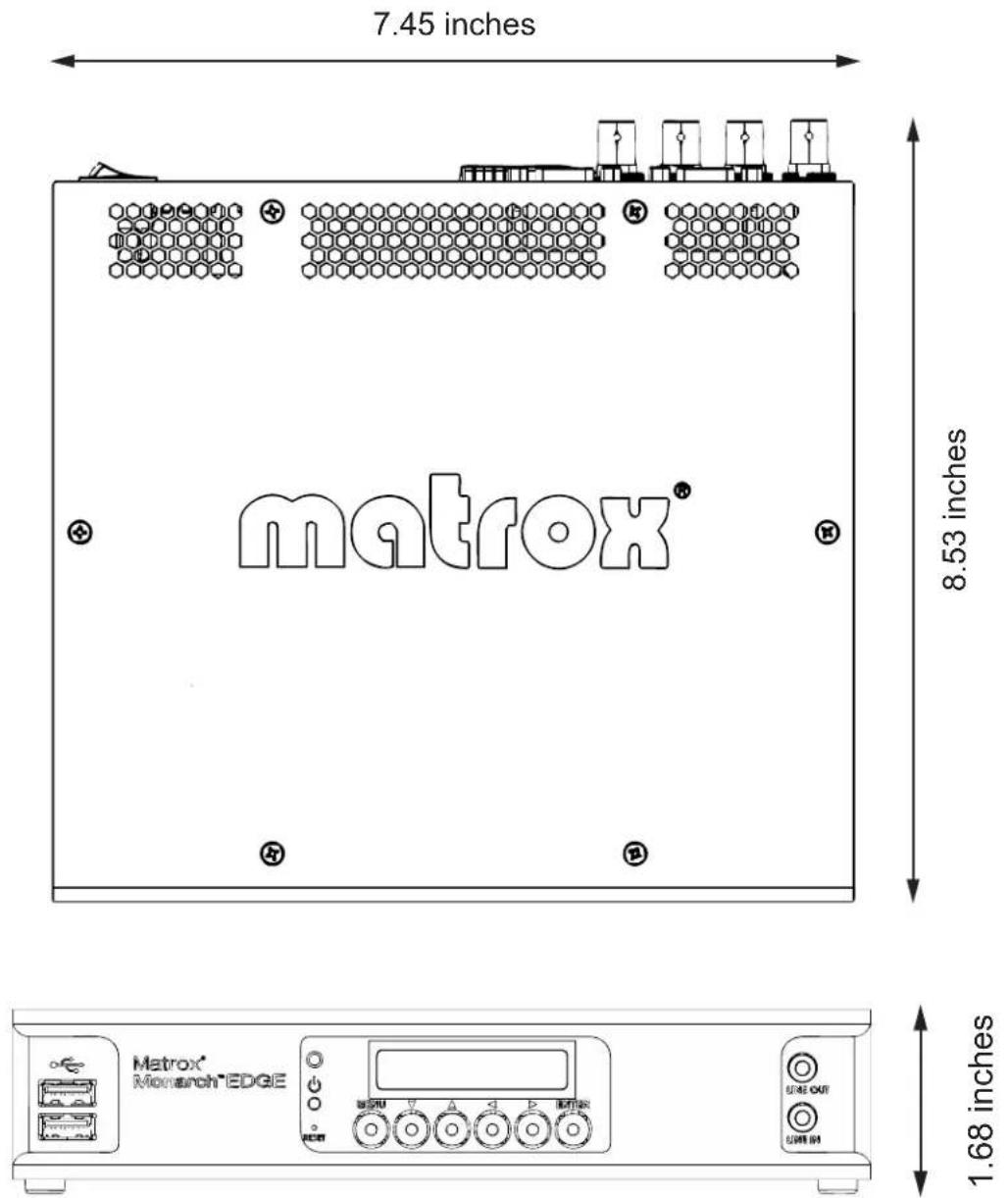
Environmental specifications
- Minimum/maximum room operating temperature: 0 to 40^
• Typical operating temperature: 25^ C - Minimum/maximum storage temperature: -20 to 60^ C
• Maximum altitude for operation: 3,000 meters
• Maximum altitude for transport: 12,000 meters - Operating humidity: 20 to 80% relative humidity (non-condensing)
- Storage humidity: 5 to 95% relative humidity (non-condensing)
Appendix B
Tally and GPIO circuits
This appendix includes the following topics:
- Monarch EDGE D4
- Output wiring
• Monarch EDGE E4 and S1
Monarch EDGE E4 and S1
Electrical characteristics
The following table describes the electrical characteristics of the GPIO circuit.
| Parameter | Conditions | Typical | Maximum | Units |
| Output Operation Voltage | N/A 12 N/A V | |||
| Output current sink | Typical: using 10k pull-up resistor. | 1.2 100 mA | ||
| Input operation voltage | N/A | 12 N/A | V |
Connector wiring pinout
The following table shows the connector pinout for the Tally connector.
| Connector Pin Description Comments | |||
Female DSUB-15 Connector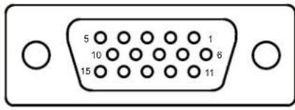 | 1 | G P | I I |
| 2 | G P | I I | |
| 3 | K e | y L | |
| 4 | T A | L L Y | |
| 5 | Ground | Isolated Ground | |
| 6 | T A | L L Y | |
| 7 | T A | L L Y | |
| 8 | T A | L L Y | |
| 9 | T A | L L Y | |
| 10 | TALLY OUT 8 | ||
| 11 | Ground | Isolated Ground | |
| 12 | TALLY OUT 3 | ||
| 13 | GPI IN 3 | ||
| 14 | GPI IN 4 | ||
| 15 | TALLY OUT 4 | ||
| Shield | Chassis | Chassis Ground | |
N
N
0
O
O
O U
O
O I
Monarch EDGE D4
Electrical characteristics
The following table describes the electrical characteristics of the GPIO circuit.
| Parameter Conditions Typical Maximum Units | ||||
| Output Operation Voltage N/A 12 N/A V | ||||
| Output current sink | Typical: using 10k pull-up resistor. | 1.2 | 100 | mA |
| Input operation voltage | N/A | 12 | N/A | V |
Connector wiring pinout
The following table shows the connector pinout for the Tally connector.
| Connector Pin Description Comments | ||
| Female DSUB-15 Connector | 1 TALLY IN 1 | |
| 2 TALLY IN 2 | ||
| 3 | K e y L | |
| 4 | G P I O | |
| 5 | Ground Isolated Ground | |
| 6 | G P I O | |
| 7 TALLY IN 5 | ||
| 8 TALLY IN 6 | ||
| 9 TALLY IN 7 | ||
| 10 | TALLY IN 8 | |
| 11 | Ground Isolated Ground | |
| 12 | GPI OUT 3 | |
| 13 | TALLY IN 3 | |
| 14 | TALLY IN 4 | |
| 15 | GPI OUT 4 | |
| Shield | Chassis Chassis Ground | |
Output wiring
An output should be wired as indicated below.
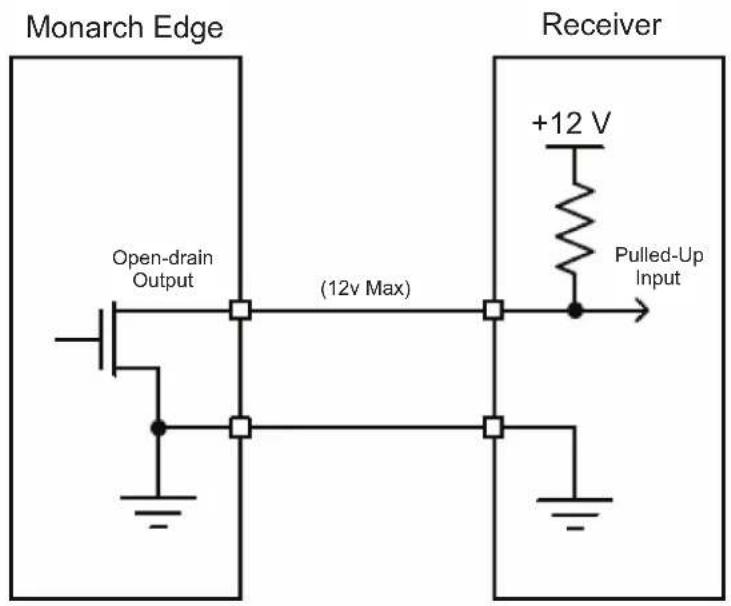
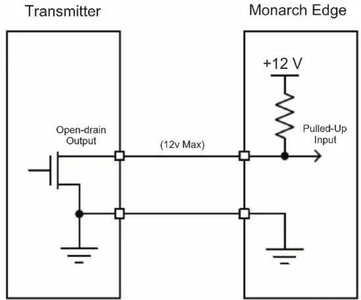
Appendix C
Analog audio cable specification
This appendix includes the following topics:
- XLR audio cable connector pinouts
XLR audio cable connector pinouts
The following table shows the pinouts for the XLR connectors on the analog audio I/O cable and the D-SUB audio connector on the Monarch Edge device.
| DSUB-15 connector(on Monarch EDGE) | Pin | Audio channel | XLR pin | Description | XLR audio cable ^1 |
| 1 | Output right | 3 | - | XLR FEMALE INPUT LEFT BALANCED 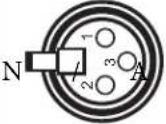 XLR FEMALE INPUT RIGHT BALANCED XLR FEMALE INPUT RIGHT BALANCED 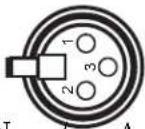 N/A XLR MALE OUTPUT LEFT BALANCED N/A XLR MALE OUTPUT LEFT BALANCED 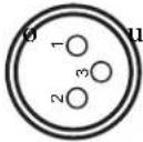 XLR MALE OUTPUT RIGHT BALANCED XLR MALE OUTPUT RIGHT BALANCED 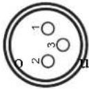 | |
| 2 | Output right | 1 | G r | ||
| 3 | Output right | 2 | + | ||
| 4 | G r | o u n d | |||
| 5 | Output left | 3 | - | ||
| 6^2 | Output left | 1 | G r | ||
| 7 | Output left | 2 | + | ||
| 8 | G r | o u n d | |||
| 9 | Input right | 3 | - | ||
| 10 | Input right | 1 | G r | ||
| 11 | Input right | 2 | + | ||
| 12 | Ground N/A | N/A | |||
| 13 | Input left | 3 | - | ||
| 14 | Input left | 1 | G r | ||
| 15 | Input left | 2 | + |
- (MDG/AUD/CBL) - Monarch EDGE break out audio cable. Provides two input channels and two output channels. DB15 to XLR I/O.
- Pin is plugged, as shown in the illustration.
Compliance Statements
USA
FCC Compliance Statement
Remark for the Matrox hardware products supported by this guide
This equipment has been tested and found to comply with the limits for a Class A digital device, pursuant to Part 15 of the FCC Rules. These limits are designed to provide reasonable protection against harmful interference when the equipment is operated in a commercial environment. This equipment generates, uses, and can radiate radio frequency energy and, if not installed and used in accordance with the instructions manual, may cause harmful interference to radio communications. Operation of this equipment in a residential area is likely to cause harmful interference in which case the user will be required to correct the interference at his own expense.
WARNING
Changes or modifications to this unit not expressly approved by the party responsible for the compliance could void the user's authority to operate this equipment. The use of shielded cables for connection of equipment and other peripherals to the card is required to meet FCC requirements.
Canada
(English) Innovation, Science and Economic Development Canada
CAN ICES-3 (A)/NMB-3 (A)
Remark for the Matrox hardware products supported by this guide
These digital devices do not exceed the Class A limits for radio noise emission from digital devices set out in the Radio Interference Regulation of Innovation, Science and Economic Development Canada.
(English) European user's information – Declaration of Conformity
Remark for the Matrox hardware products supported by this guide

These devices comply with EC Directive 2014/30/EU for a Class A digital device. They have been tested and found to comply with EN55032/CISPR32 and EN55024/CISPR24. In a domestic environment these products may cause radio interference in which case the user may be required to take adequate measures. To meet EC requirements, shielded cables must be used to connect equipment and other peripherals. These products have been tested in a typical Class A compliant host system. It is assumed that these products will also achieve compliance in any Class A compliant system.
- Matrox Monarch EDGE Series
- Installation and User Guide
- Trademarks
- Matrox Software License agreement
- (Hereafter referred to as License)
- LICENSES
- END USER LICENSE
- OEM LICENSE
- GENERAL LICENSE TERMS: (APPLICABLE TO BOTH END-USERS & OEMs)
- COPYRIGHT
- DISCLAIMER OF WARRANTIES
- LIMITATION OF LIABILITY
- TERMINATION
- MISCELLANEOUS
- Table of contents
- Chapter 1: Introduction
- Chapter 2: Hardware connections
- Chapter 3: Monarch EDGE firmware update and Control Hub installation
- Chapter 4: Network management
- Chapter 5: User and device management
- Chapter 6: Monarch EDGE Control Hub configuration
- Chapter 7: Monarch EDGE Command Center configuration
- Appendix A: Technical specifications
- Appendix B: Tally and GPIO circuits
- Appendix C: Analog audio cable specification
- CHAPTER 1
- Introduction
- About the Matrox Monarch EDGE Series
- Matrox Monarch EDGE E4 and Monarch EDGE D4
- Matrox Monarch EDGE S1
- Matrox Monarch EDGE Control Hub
- Matrox Monarch EDGE Command Center
- Matrox Monarch EDGE RESTful API
- System requirements
- Installation and configuration overview
- CHAPTER 2
- Hardware connections
- Matrox Monarch EDGE front connections
- Matrox Monarch EDGE E4 and D4 rear connections
- Matrox Monarch EDGE S1 rear connections
- Matrox Monarch EDGE front panel
- Description of LEDs
- CHAPTER 3
- Monarch EDGE firmware update and Control Hub installation
- If you are using Monarch EDGE Command Center
- Update and installation prerequisites
- Updating the Monarch EDGE firmware
- Step 5. Click on the Monarch EDGE devices to update, then click Update.
- Step 6. If the Monarch EDGE device you are trying to update is already part of an EDGE environment (see "User and device management" on page 21), the following message will be displayed.
- Installing Monarch EDGE Control Hub
- Uninstalling or repairing Monarch EDGE Control Hub
- CHAPTER 4
- Network management
- About Matrox Monarch EDGE device discovery
- Discovering devices automatically
- Discovering devices manually
- Assigning a static IP address to a Monarch EDGE
- Monarch EDGE firewall requirements
- CHAPTER 5
- User and device management
- About User and Device Management
- Starting up Matrox Monarch EDGE Control Hub
- Monarch EDGE Control Hub
- Yes
- No
- Environment administrator accounts
- About environment administrators
- Creating an environment administrator account
- User accounts
- About user accounts
- Creating a user account
- Step 5. Click Apply.
- Managing users and device permissions
- Transferring control to a different environment administrator
- Changing the environment password
- Changing user accounts
- Managing user accounts and permissions
- CHAPTER 6
- Monarch EDGE Control Hub configuration
- This chapter includes the following topics:
- Monitoring Monarch EDGE devices
- About the Monarch EDGE Control Hub user interface
- Using the contextual menu for encoder and decoder settings
- Configuring Encoder Processing settings
- Inputs/Outputs
- Processing
- Encodings
- Streams
- Recordings
- Configuring Decoder Processing settings
- Input streams
- SDI Outputs
- Configuring Network settings
- Configuring Date and Time settings
- Date and time
- Time zone
- Configuring Genlock settings
- Genlock
- Configuring DP Output settings
- NOTES
- Configuring Tally settings
- About Test Mode and Live Mode
- Testing your Tally and GPI connections
- To use Test mode:
- Using your Tally and GPI connections
- Configuring Talkback settings
- Managing Logs
- Managing configurations
- Grouping Monarch EDGE devices
- CHAPTER 7
- Monarch EDGE Command Center configuration
- About Monarch EDGE Command Center
- Logging in to Monarch EDGE Command Center
- About the Monarch EDGE Command Center user interface
- Configuring Encode settings
- Inputs/Output
- Input processes
- Configuring Decode settings
- Audio Output
- Managing SyncGroups
- Configuring User management settings
- Step 1. Go to the
- User management section in Monarch EDGE Command Center.
- Step 2. To add a new user, click
- Add user.
- Step 3. Type the
- Step 4. Click Add user.
- Step 5. (Optional) Click
- Appendix A
- Technical specifications
- General
- Power Supply:
- International Adapter
- Connections
- SDI connections:
- Data ports:
- Balanced analog audio input:
- Balanced analog audio output:
- Configurable genlock:
- Tally I/O:
- MDG2/ED10/I
- - Audio processing
- Compression
- Codecs:
- Bitrate per stream:
- Chroma sub-sampling:
- Encoding controls:
- Decoding controls:
- Profile:
- Latency:
- Dimensions
- Environmental specifications
- Appendix B
- Tally and GPIO circuits
- Monarch EDGE E4 and S1
- Electrical characteristics
- Connector wiring pinout
- Monarch EDGE D4
- Output wiring
- Appendix C
- XLR audio cable connector pinouts
- Compliance Statements
- USA
- FCC Compliance Statement
- WARNING
- Canada
- (English) Innovation, Science and Economic Development Canada
- CAN ICES-3 (A)/NMB-3 (A)
- (English) European user's information – Declaration of Conformity
Brand : MATROX
Model : Edge Encoder
Category : Audio/video converter