
43224-32 - Tent Gazebo Penguin - Free user manual and instructions
Find the device manual for free 43224-32 Gazebo Penguin in PDF.


| Product Type | Tent |
| Brand | Gazebo Penguin |
| Model | 43224-32 |
| Capacity | 3-4 persons |
| Dimensions (L x W x H) | 210 x 210 x 130 cm |
| Weight | 5.5 kg |
| Material - Flysheet | Polyester 190T with PU coating |
| Material - Inner | Breathable polyester mesh |
| Material - Poles | Fiberglass |
| Floor material | Polyethylene reinforced |
| Waterproof rating | 2000 mm |
| Seam sealing | Taped seams |
| UV protection | UPF 50+ |
| Setup type | Free-standing dome |
| Doors | 2 |
| Windows | 2 mesh windows with cover |
| Ventilation | Adjustable vents |
| Included accessories | Carry bag, stakes, guy ropes |
| Fire retardant | Yes (CPA 84 compliant) |
| Cleaning instructions | Hand wash with mild soap, air dry |
| Storage | Store in a cool, dry place |
| Warranty | 1 year limited |
Frequently Asked Questions - 43224-32 Gazebo Penguin
User questions about 43224-32 Gazebo Penguin
0 question about this device. Answer the ones you know or ask your own.
Ask a new question about this device
Download the instructions for your Tent in PDF format for free! Find your manual 43224-32 - Gazebo Penguin and take your electronic device back in hand. On this page are published all the documents necessary for the use of your device. 43224-32 by Gazebo Penguin.
USER MANUAL 43224-32 Gazebo Penguin
natural_image
Silhouette of a penguin standing upright (no text or symbols)GAZEBO penguin inc.
4660 HICKMORE ST,
MONTREAL, QUEBEC
H4T 1K2
TEL: 1-514-276-3485. 1-800-737-7174
Email: customerservice@gazebopenguin.com
PLEASE READ IN ITS ENTIRETY BEFORE INSTALLATION
43224-22 BROWN
43224-32 SLATE
PLEASE READ IN ITS ENTIRETY BEFORE INSTALLATION
12'x14' GAZEBO ASSEMBLY INSTRUCTIONS

natural_image
Line drawing of a rectangular metal enclosure with triangular roof structure (no text or symbols)DO NOT DESTROY THE BOXES UNTIL COMPLETELY ASSEMBLED PLEASE VERIFY THE CONTENT OF EACH BOX AGAINST THE LIST OF PARTS
Assembly With Two Or More Adults Recommended
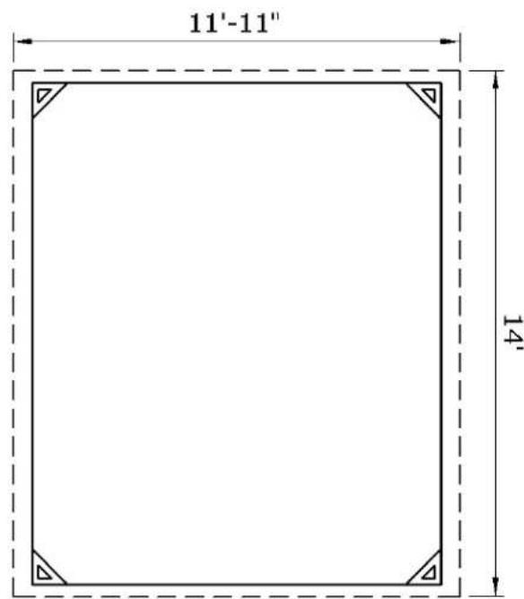
Base Dimensions 10' 11" x 13' 4"
Largest Dimensions 11' 11" x 14'
APPROX.
Overall Height 108.5"
DO NOT DESTROY THE BOXES UNTIL COMPLETELY ASSEMBLED
PLEASE VERIFY THE CONTENT OF EACH BOX AGAINST THE LIST OF PARTS
12ft x 14ft / 3.65m x 4.26m GAZEBO
Instruction Manual
IMPORTANT: RETAIN FOR FUTURE REFERENCE, READ CAREFULLY
Consult with your local governing authority / local municipal codes regarding installation of temporary structures before purchase or assembly. Some jurisdictions may require permits for, or otherwise regulate, installation and use.
For assistance with assembly, installation, parts, or customer service, contact Gazebo Penguin Customer
Service Department at the numbers listed below (English & French, Mon-Fri 8:00 AM to 4:00 PM EST):
Montreal: (514) 276-3485
Elsewhere in Canada and the US: 1-800-737-7174
WARNING:
- For outdoor use.
- Snow should be regularly cleared from the roof and not allowed to accumulate.
- Retain your proof of purchase for warranty purposes. Also keep the original boxes until the installation is complete and correct.
- The unit may take more than 4 hours and 3 people are required for this assembly.
PRIOR TO ASSEMBLY:
- Please don't destroy boxes until completely assembled.
- The foundation must be level, flat, and solid, such as concrete or asphalt.
- Keep away from overhead utility lines, tree branches, and other structures.
- Check for underground pipes or wires if digging or drilling is required.
- Do not install near roof lines or other structures that could shed snow, ice, or excessive rain run-off onto the roof top.
- Assemble the structure as close to its final location as possible.
- It is recommended to wear safety gloves, safety glasses, and hard hats for installation.
- Do not hang from, climb on, or stand on the structure or roof.
- Before assembly, read instructions and check that all parts are present in the boxes. If any parts are missing, refer to warranty information.
- A 6ft (1.8m) stepladder, Phillips screwdriver, tape measure, level, mallet, and a tarp to place parts on will be required for assembly (not included).
- Remove top protective film from roof panels prior to assembly; DO NOT remove bottom protective film until ready to insert roof panels, so as to identify which side is on top.
ANCHORING INSTRUCTIONS:
- Proper anchoring of the frame to the base and the wall is required for safety.
• Any structure not anchored securely has the potential to fly away during high wind causing damage and safety hazard.
• How the item is anchored, and the hardware and tools required, will vary based upon the set-up location and are not provided. - Please check with your local hardware store if for the appropriate anchors for your surface.
- Do not anchor to pavers / pavement slabs because they are not a solid foundation.
• Periodically check the anchors to ensure they remain secure
CARE AND MAINTENANCE:
- In case of a defective or damaged part, or for any other questions concerning the product, please contact the manufacturer directly.
- Please have the parts list and part numbers on hand when ordering or requesting replacement parts.
ROOF PANELS:
• Gently clean with an environmentally-friendly soap solution and water using a sponge or washcloth.
- Do not use abrasive materials, wire brushes, chemicals, harsh cleaners, or bleach.
- Rinse using a garden hose and air dry. If removed, ensure thoroughly dry prior to storage.
- Do not use pressure washer.
STRUCTURE:
• Gently clean with an environmentally-friendly soap solution and water using a sponge or washcloth.
- Do not use abrasive materials, wire brushes, chemicals, harsh cleaners, or bleach.
- Rinse using a garden hose and air dry.
- Do not use pressure washer.
• If there are nicks, chips, and/or scratches see the part # of the paint in the parts list to obtain a matching touch-up paint.


MAINTENANCE NOTES
- In case of a defective or damaged part, or for any other questions concerning the product, please contact the manufacturer directly.
- Please have the parts list and part numbers on hand when ordering or requesting replacement parts.
- The product should not be installed adjacent to trees or a sloped roof. Snow and ice may slide onto the roof and cause it to collapse.
- While the product is designed to stay assembled year long, the roof must be kept free of accumulation of snow.

natural_image
Simple line drawing of a barn and tree with a red X mark, enclosed in a red rounded rectangle (no text or symbols)ONE YEAR LIMITED WARRANTY
This product has been designed and manufactured to meet the highest standards of quality and durability. Subject to the Conditions for Exercising the Warranty and the Limitations on the Warranty set forth below, it is warranted to be free of material and manufacturing defects for a period of one year from the date of purchase. Missing and damage due to transportation is not covered by the manufacture warranty. Should the product become damaged, or the warranty period has expired, please contact Gazebo Penguin Customer Service Department for a complete schedule of replacement parts and prices.
CONDITIONS FOR EXERCISING THE WARRANTY
The warranty only applies to the original purchaser with the bill.
In order to properly exercise your warranty, please comply with the following:
Carefully inspect the contents of the carton for missing or damaged components. Should you discover damaged or missing parts, do not return the product to the place of purchase, but contact Gazebo Penguin Customer Service Department at the numbers listed below:
Montreal: (514) 276-3485
Elsewhere: 1-800-737-7174
You can also find a claim form to fill out online:
https://abrispenguin.com/assemblyinstructions/
NOTE: Damages/missing parts must be reported within 30 days of delivery. If claimed after your request might be rejected.
LIMITATIONS ON THE WARRANTY
- The product is not warranted against damages due to vandalism, abuse, falling or thrown objects, or accumulation of snow.
- The product is not warranted against damages due to extreme weather conditions, such as thunderstorms, hail, strong wind or snow storms, or any other acts of God.
- Leaking due to heavy rain may happen, please refer to the instruction manual for window positions and information on how to evacuate the water.
- The product is only warranted in the event it is installed in accordance with the Gazebo Penguin's written instructions enclosed with the product.
- The product is not warranted in the event it has been improperly anchored.
- We reserve the right to replace or repair any defective product or parts at our discretion.
- No change to the unit is allowed. This will void your warranty.
Before You Assemble the Gazebo
PLEASE DON'T DESTROY BOXES UNTIL COMPLETELY ASSEMBLED
- Please verify the content of each box against the list of parts.
- It is important that this gazebo be anchored on a solid base with the provided screws. Otherwise, please ensure that you use anchors sufficient for your surface.
- The gazebo should not be installed adjacent to trees or a sloped roof. Snow and ice may slide onto the gazebo and cause it to collapse.
Tools required (Not Provided)
- 6ft (1.8m) Stepladder
• Robinson #2 Screwdriver - Mallet
• Safety Gloves & Glasses -
Shim
-
Tarp or protective material for placing parts on during assembly
- Tape Measure
- Leveling
Step 1:
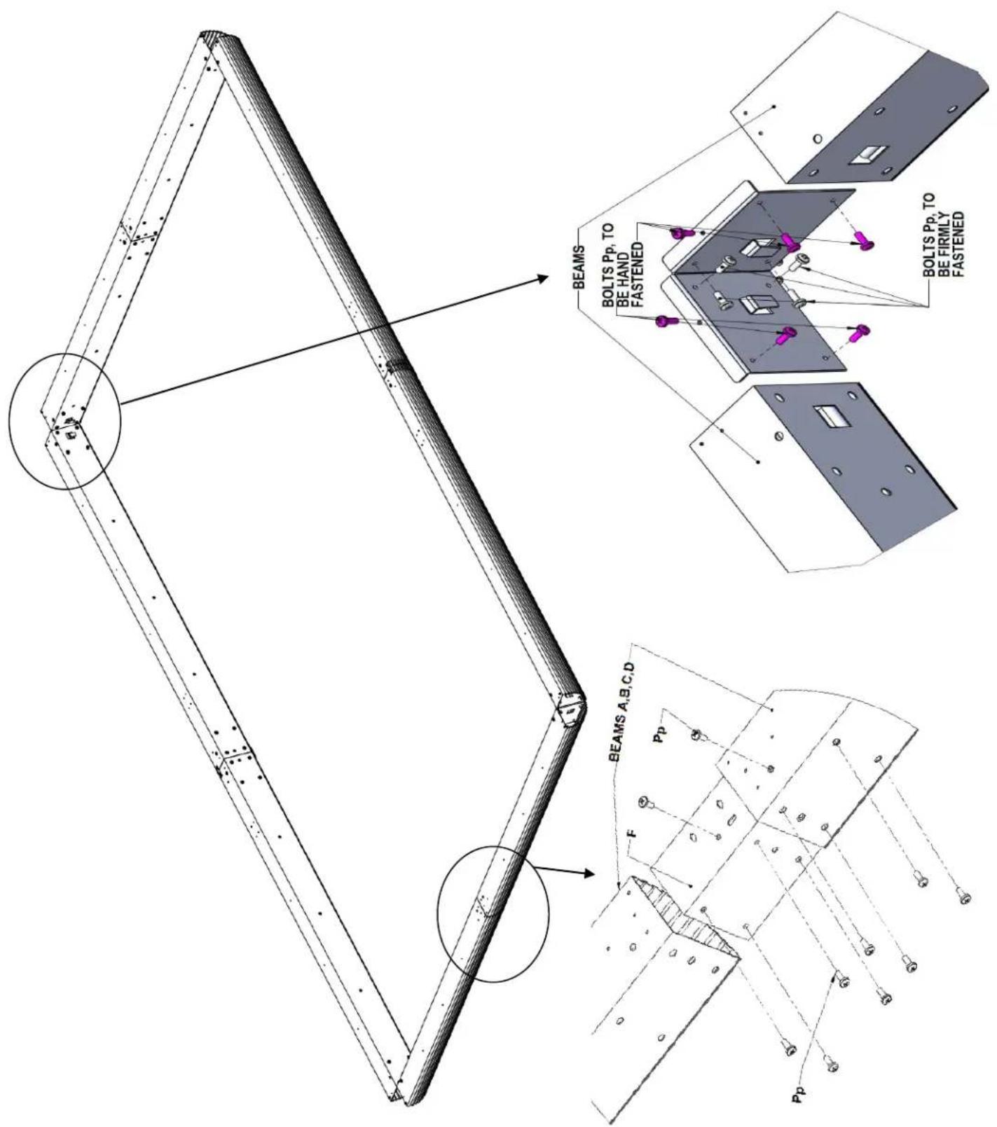
- Assemble Beams "A" and "B" using Center Plate "F", by sliding it inside the beams and securely tighten with 10 Bolts "Pp". Repeat with Beams "C" and "D", also using Center Plate "F".
- Lay out the assembled Beams in a rectangle and join at each corner with a Corner Plate "E", by sliding it inside the beams and tighten it with 4 Bolts "Pp" tightly and hand fasten remaining 4 Bolts in pink. – see image on pg. 5

Step 2:
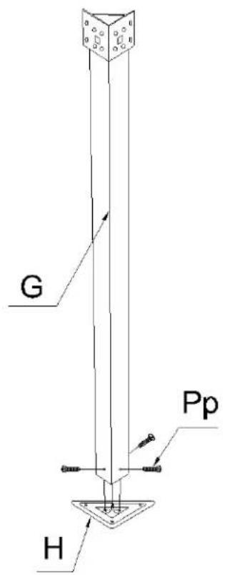
For each leg "G", attach foot plate "H" using 3 bolts "Pp".
Step 3:
-
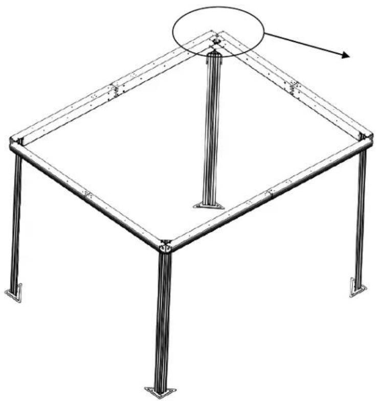
Unscrew 4 Pp Bolts as shown below, have someone lift the Beam assembly and attach each Leg "G" into a Corner, again securing each using 4 Bolts "Pp".
-
Repeat until all four Legs are in place
natural_image
Technical line drawing of a square frame structure with vertical supports and a circular top component (no text or symbols)
Step 4:
- Install Middle Cover "J" at each of the 4 beam junctions, using 4 Screws "Qq" each.
- Install Corner Cover "I" at each of the corners, using 4 Screws "Qq" each.

Step 5:
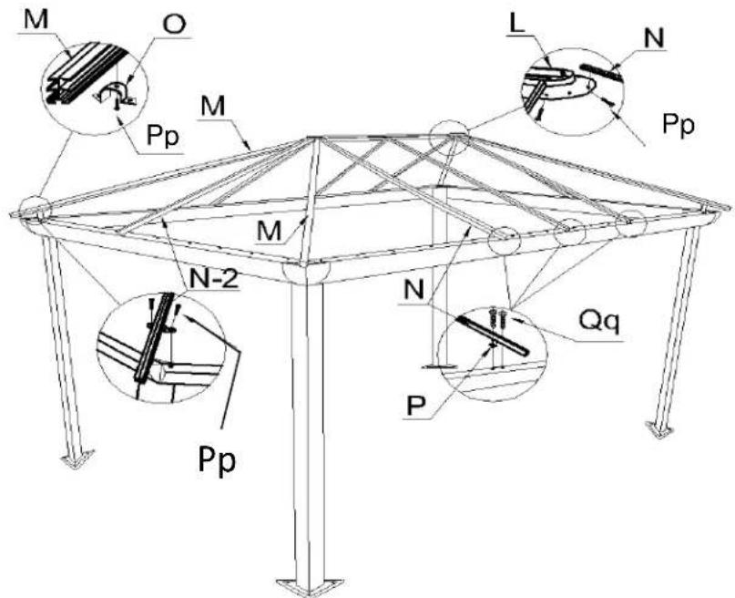
- Attach Mounting Brackets "O" to Rafters "M", and Mounting Brackets "P" to Rafters "N" and "N-2". Use threaded hole about 8 12 & 5" from end of rafter.
- Lift Central Hub "L" to a height of about 110" (2.79m) at the center of the gazebo. (Caution: this part may be heavy, use support as needed)
- Attach one end of Rafter "M" to the hub using 1 Bolt "Pp". Attach other end with Mounting Bracket to the corner of the beam assembly with 2 Bolts "Pp". Use the set of holes closest to the inside. Repeat with remaining "M" Rafters.
- Similarly, attach one end of Rafter "N" to the hub using 1 Bolt "Pp". Attach other end with mounting bracket to the beam assembly with 2 Screws "Qq". Use the set of holes closest to the inside. Repeat with remaining "N" and "N-2" Rafters.
Step 6:
- Once all rafters are in place, install Top Cap "K" over Central Hub "L". Use flat Washers and Acorn Nuts "Vv" to secure tightly.

Step 7:
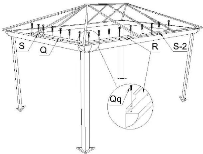
Install the flashings "Q", "R", "S", and "S-2" onto the beam assembly, using screws "Qq" on the inside. The notched end of a flashing will always go in a corner of the gazebo.
Step 8:
Install the curtain rails "T" and "U" on the inside of the beam assembly using bolts "Pp".

Step 9:
Slide the indicated polycarbonate panels into the spaces between the rafters, using the top groove of each rafter. Ensure the side meant to face the sun is on the outside. Use a rubber hammer to carefully tap each panel into the grooves.

flowchart
graph TD
    A["Block W"] --> B["Block X"]
    A --> C["Block V"]
    B --> D["Arrow N-2"]
    C --> E["Arrow N-2"]
    D --> F["Center Node"]
    E --> F
    F --> G["Block X-2"]
    F --> H["Block V-2"]
    G --> I["Arrow N-2"]
    H --> J["Arrow N-2"]
    I --> K["Center Node"]
    J --> L["Center Node"]
    K --> M["Block W"]
    K --> N["Block W"]
    L --> O["Arrow N-2"]
    M --> P["Arrow N-2"]
    N --> Q["Arrow N-2"]
    O --> R["Center Node"]
    P --> S["Center Node"]
Step 10:
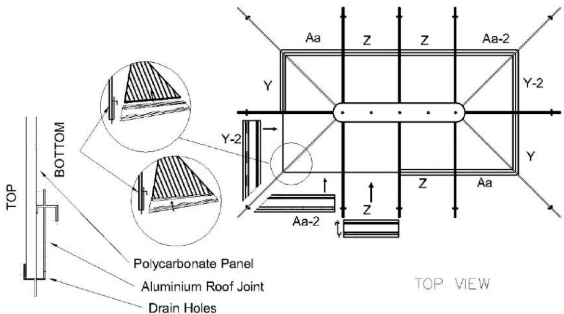
Insert the middle roof joints in between the rafters and slide them up under the polycarbonate panels. Tap lightly to ensure the panel is fully in the slot. Seen from above, most of the joint as well as the drain holes should be beneath the roof panels.
To adjust the middle joints to line up : once all polycarbonate roof panels are in place, use a small piece of wood and hammer, then tap down on the middle of the joint bringing it down and holding at the same time the joint and top polycarbonate.
Do not tap too hard.
Step 11:
- Slide the remaining polycarbonate roof panels in the lower groove of the rafters and into the lower slot of the roof joints. Tap to make sure panels fit securely and do not extend past the ends of the rafters.

Step 12:
- Starting from any end, install all edgings, with end caps "Gg" or "Hh" at each junction or corner respectively. Use bolts "Pp" to secure.

Step 13:
-
Install the upper crossbars on the interior of the roof using bolts "Pp", following the shaped ends and letters. Do not tighten bolts immediately; install loose and tighten once all crossbars are in place.
-
Repeat this step with the lower crossbars.

Step 14:
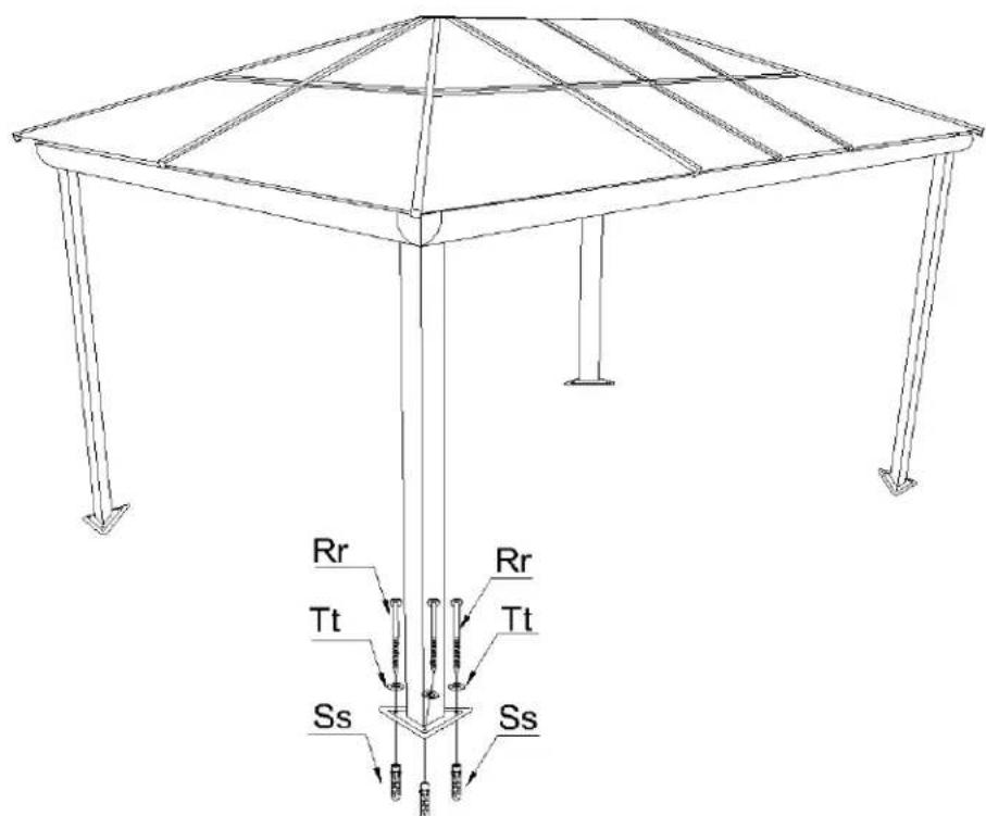
- Secure each foot plate into the ground using screws "Rr" and Washers "Tt".
- Use lag shields (Ss) if needed for harder surfaces.
Step 15:
- Install the Screen Curtains "Ww" in the interior groove of the Curtain Rails, using the provided hooks. Install the Privacy Curtains "Xx" in the exterior groove of the rails. Once the hooks are in, use Curtain Rail Caps "Uu" to close ends of curtain rails.
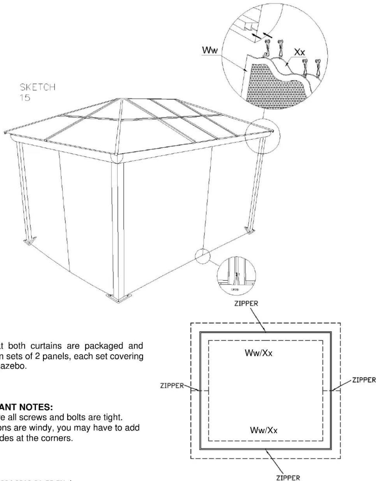
Note that both curtains are packaged and ordered in sets of 2 panels, each set covering half the gazebo.
IMPORTANT NOTES:
Make sure all screws and bolts are tight. If conditions are windy, you may have to add cable guides at the corners.
43224 BROWN (see page 18 for Slate parts)
| PART | PACKED IN BOX | QTY | DIAGRAM | PART | PACKED IN BOX | QTY | DIAGRAM |
| (11-626-22)65 1⁄2"TOP LEFT BEAMA | 3 | 2 | 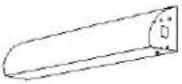 | (11-665-22)60"CENTRAL HUBL | 2 | 1 |  |
| (11-627-22)65 1⁄2"TOP RIGHT BEAMB | 3 | 2 | 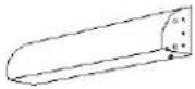 | (11-731-22)92 5/8"ROOF RAFTERM | 2 | 4 |   |
| (11-662-22)78 1⁄4"TOP LEFT BEAMC | 3 | 2 | 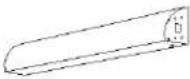 | (11-708-22)73 3⁄4"ROOF RAFTERN | 2 | 6 |   |
| (11-663-22)78 1⁄4"TOP RIGHTBEAMD | 3 | 2 |  | (11-637-22)60 3/8"ROOF RAFTERN-2 | 2 | 2 | [TW6S] |
| (11-628-22)CORNER PLATEE | 3 | 4 |  | (12-030-22)RAFTER MMOUNTINGBRACKETO | 2 | 4 |  |
| (11-629-22)CENTER PLATEF | 3 | 4 |  | (12-031-22)RAFTER NMOUNTINGBRACKETP | 2 | 8 |  |
| (11-630-22) 81 1⁄2"LEGG | 3 | 4 |  | (11-638-22)55 1⁄4"RIGHTFLASHINGQ | 2 | 4 | 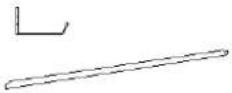 |
| (11-631-22)FOOT PLATEH | 3 | 4 |  | (11-639-22)55 1⁄4"LEFT FLASHINGR | 2 | 4 |  |
| (11-632-22)CORNER COVERI | 3 | 4 |  | (11-640-22)25 3/8"CENTERFLASHINGS | 2 | 2 | 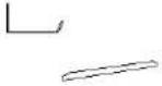 |
| (11-633-22)MIDDLE COVERJ | 3 | 4 |  | (11-709-22)51"CENTERFLASHINGS-2 | 2 | 2 |  |
| (11-664-22)63"TOP CAPK | 2 | 1 |  | (11-666-22)73 1⁄4" CURTAIN RAIL, 14' SIDE T | 2 | 4 | 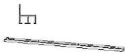 |
| (11-641-22)60 1⁄2" CURTAIN RAIL, 12' SIDE U | 2 | 4 |  | (11-678-22)32 1⁄4"x72" LEFT LOWER PANEL, 12'SIDE Bb | 1 | 2 | 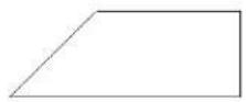 |
| (11-674-22)31"x38"LEFT UPPER PANEL, 12' SIDE V | 1 | 2 | 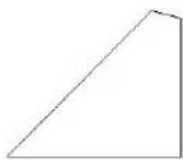 | (11-721-22)39"x57 1⁄2" LEFT LOWER PANEL, 14'SIDE Bb-2 | 1 | 2 | 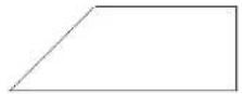 |
| (11-711-22)31"x38"RIGHT UPPER PANEL, 12' SIDE V-2 | 1 | 2 |  | (11-679-22)32 1⁄4"x72"RIGHT LOWER PANEL, 12'SIDE Cc | 1 | 2 |  |
| (11-734-22)37"x25 1⁄2"MIDDLE UPPER ROOF PANEL W | 1 | 4 | 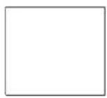 | (11-722-22)39"x57 1⁄2"RIGHT LOWER PANEL, 14'SIDE Cc-2 | 1 | 2 |  |
| (11-675-22)37 1⁄2"x30 1⁄2"RIGHT UPPER PANEL, 14' SIDE X | 1 | 2 |  | (11-680-22)72 5/8"LEFT EDGING, 12'SIDE Dd | 2 | 2 | 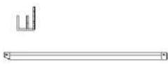 |
| (11-712-22)37 1⁄2"x30 1⁄2"LEFT UPPER PANEL, 14' SIDE X-2 | 1 | 2 |  | (11-715-22)72 5/8"RIGHT EDGING, 12'SIDE Dd-2 | 2 | 2 |  |
| (11-676-22)38 1⁄2"LEFT MID ROOF JOINT, 12' SIDE Y | 2 | 2 |  | (11-652-22)26 3⁄4"CENTER EDGING Ee | 2 | 4 | 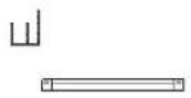 |
| (11-713-22)38 1⁄2"RIGHT MIDROOF JOINT12' SIDEY-2 | 2 | 2 |  | (11-653-22)58 7/8"RIGHTEDGING,14' SIDEFf | 2 | 2 |  |
| (11-647-22)25 1⁄2"CENTERMIDDLEROOF JOINTZ | 2 | 4 |  | (11-651-22)58 7/8"LEFTEDGING,14' SIDEFf-2 | 2 | 2 |  |
| (11-677-22)31"RIGHT MIDROOFJOINT, 14'SIDEAa | 2 | 2 |  | (11-654-22)RAFTERCAPGg | 2 | 8 |  |
| (11-714-22)31"LEFT MIDROOFJOINT, 14'SIDEAa-2 | 2 | 2 |  | (11-655-22)CORNERENDBRACKETHh | 2 | 4 |  |
| (11-682-22)43 1⁄4"LEFT LOWERCROSSBAR,14' SIDELi | 2 | 2 |  | (08-158-22)BOLTPp | 3 | 196 |   |
| (11-717-22)43 1⁄4"RIGHTLOWERCROSSBAR,14' SIDELi-2 | 2 | 2 | [W3D] | (08-156-22)SCREWQq | 3 | 108 |  (M4x16mm) (M4x16mm) |
| (11-657-22)26 3⁄4"MIDDLELOWERCROSSBARJj | 2 | 4 |  | (08-167-22)SCREWRr | 3 | 12 | 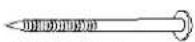 (M6x100mm) (M6x100mm) |
| (11-683-22)53 1⁄2"RIGHTLOWERCROSSBAR,12' SIDEKk | 2 | 2 |  | (08-193-22)PLASTIC PLUGSs | 3 | 12 | [2088] |
| (08-187-22)WASHERTt | 3 | 16 | [IMAGE] | ||||
| (11-718-22)53 1⁄2"LEFT LOWERCROSSBAR,12' SIDEKk-2 | 2 | 2 |  | (11-697-22)CURTAIN RAIL CAPUu | 3 | 8 |  |
| (08-189-22)ACORNNUTVv | 3 | 4 | [IMAGE] | ||||
| (11-685-22)20 1⁄2"RIGHT UPPERCROSSBAR,12' SIDELI | 2 | 2 |  | (11-686)SCREEN/MOUSTIQUAIREWw | 2 | 4 |  |
| (11-720-22)20 1⁄2"LEFT UPPERCROSSBAR,12' SIDELI-2 | 2 | 2 |  | (11-687)PRIVACY CURTAINXx | 2 | 2Left | 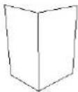 |
| 2Right | |||||||
| (11-660-22)26 3⁄4"MIDDLEUPPERCROSSBARMm | 2 | 4 |  | (11-698)38"x25 1⁄2"MIDDLE LOWER ROOF PANELYy | 1 | 2Left |  |
| 2Right | |||||||
| (11-659-22)17 1⁄2"LEFT UPPERCROSSBAR,14' SIDENn | 2 | 2 |  | (11-705)CURTAIN HOOKS | 3 | 104 | [IMAGE] |
| (11-661-22)17 1⁄2"RIGHT UPPERCROSSBAR,14' SIDENn-2 | 2 | 2 |  | *NOT INCLUDED IN THE BOX | |||
| DESCRIPTION | COLOUR | PART # | |||||
| SPRAYPAINT | BROWN | 11-726 | |||||
| PAINT PEN | 18-184 | ||||||
| 10 mm KEY | 3 | 1 | |||||
43224 SLATE
| PART | PACKED IN BOX | QTY | DIAGRAM | PART | PACKED IN BOX | QTY | DIAGRAM |
| (11-626-32)65 1⁄2"TOP LEFT BEAMA | 3 | 2 |  | (11-665-32)60"CENTRAL HUBL | 2 | 1 | 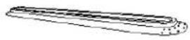 |
| (11-627-32)65 1⁄2"TOP RIGHT BEAMB | 3 | 2 | 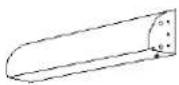 | (11-731-32)92 5/8"ROOF RAFTERM | 2 | 4 |  |
| (11-662-32)78 1⁄4"TOP LEFT BEAMC | 3 | 2 | 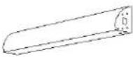 | (11-708-32)73 3⁄4"ROOF RAFTERN | 2 | 6 |  |
| (11-663-32)78 1⁄4"TOP RIGHTBEAMD | 3 | 2 | 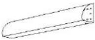 | (11-637-32)60 3/8"ROOF RAFTERN-2 | 2 | 2 | 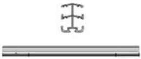 |
| (11-628-32)CORNER PLATEE | 3 | 4 |  | (12-030-32)RAFTER MMOUNTINGBRACKETO | 2 | 4 |  |
| (11-629-32)CENTER PLATEF | 3 | 4 |  | (12-031-32)RAFTER N MOUNTINGBRACKETP | 2 | 8 |  |
| (11-630-32)81 1⁄2"LEGG | 3 | 4 |  | (11-638-32)55 1⁄4"RIGHTFLASHINGQ | 2 | 4 | 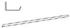 |
| (11-631-32)FOOT PLATEH | 3 | 4 |  | (11-639-32)55 1⁄4"LEFT FLASHINGR | 2 | 4 |  |
| (11-632-32)CORNER COVERI | 3 | 4 | 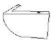 | (11-640-32)25 3/8"CENTERFLASHINGS | 2 | 2 | 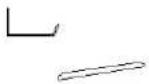 |
| (11-633-32)MIDDLE COVERJ | 3 | 4 |  | (11-709-32)51"CENTERFLASHINGS-2 | 2 | 2 |  |
| (11-664-32)63"TOP CAPK | 2 | 1 |  | (11-666-32)73 1⁄4" CURTAIN RAIL, 14' SIDE T | 2 | 4 |  |
| (11-641-32)60 1⁄2" CURTAIN RAIL, 12' SIDE U | 2 | 4 |  | (11-678-32)32 1⁄4"x72" LEFT LOWER PANEL, 12'SIDE Bb | 1 | 2 |  |
| (11-674-32)31"x38" LEFT UPPER PANEL, 12' SIDE V | 1 | 2 |  | (11-721-32)39"x57 1⁄2" LEFT LOWER PANEL, 14'SIDE Bb-2 | 1 | 2 |  |
| (11-711-32)31"x38" RIGHT UPPER PANEL, 12' SIDE V-2 | 1 | 2 |  | (11-679-32)32 1⁄4"x72"RIGHT LOWER PANEL, 12'SIDE Cc | 1 | 2 |  |
| (11-734-32)37"x25 1⁄2"MIDDLE UPPER ROOF PANEL W | 1 | 4 |  | (11-722-32)39"x57 1⁄2"RIGHT LOWER PANEL, 14'SIDE Cc-2 | 1 | 2 |  |
| (11-675-32)37 1⁄2"x30 1⁄2"RIGHT UPPER PANEL, 14' SIDE X | 1 | 2 |  | (11-680-32)72 5/8"LEFT EDGING, 12'SIDE Dd | 2 | 2 |  |
| (11-712-32)37 1⁄2"x30 1⁄2"LEFT UPPER PANEL, 14' SIDE X-2 | 1 | 2 |  | (11-715-32)72 5/8"RIGHT EDGING, 12'SIDE Dd-2 | 2 | 2 |  |
| (11-676-32)38 1⁄2"LEFT MID ROOF JOINT, 12' SIDE Y | 2 | 2 |  | (11-652-32)26 3⁄4"CENTER EDGING Ee | 2 | 4 | 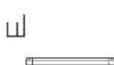 |
| (11-713-32)38 1⁄2"RIGHT MIDROOF JOINT12' SIDEY-2 | 2 | 2 |  | (11-653-32)58 7/8"RIGHTEDGING,14' SIDEFf | 2 | 2 | 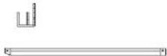 |
| (11-647-32)25 1⁄2"CENTERMIDDLEROOF JOINTZ | 2 | 4 | 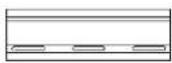 | (11-651-32)58 7/8"LEFTEDGING,14' SIDEFf-2 | 2 | 2 |  |
| (11-677-32)31"RIGHT MIDROOFJOINT, 14'SIDEAa | 2 | 2 | 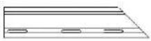 | (11-654-32)RAFTERCAPGg | 2 | 8 |  |
| (11-714-32)31"LEFT MIDROOFJOINT, 14'SIDEAa-2 | 2 | 2 | 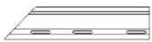 | (11-655-32)CORNERENDBRACKETHh | 2 | 4 |  |
| (11-682-32)43 1⁄4"LEFT LOWERCROSSBAR,14' SIDELi | 2 | 2 | [SXGA] | (08-158-32)BOLTPp | 3 | 196 |  (M6x16mm) (M6x16mm) |
| (11-717-32)43 1⁄4"RIGHTLOWERCROSSBAR,14' SIDELi-2 | 2 | 2 | [Z2CS] | (08-156-32)SCREWQq | 3 | 108 |  (M4x16mm) (M4x16mm) |
| (11-657-32)26 3⁄4"MIDDLELOWERCROSSBARJj | 2 | 4 |  | (08-167-32)SCREWRr | 3 | 12 |  (M6x100mm) (M6x100mm) |
| (11-683-32)53 1⁄2"RIGHTLOWERCROSSBAR,12' SIDEKk | 2 | 2 |  | (08-193-32)PLASTIC PLUGSs | 3 | 12 | |
| (08-187-32)WASHERTt | 3 | 16 | |||||
| (11-718-32)53 1⁄2"LEFT LOWERCROSSBAR,12' SIDEKk-2 | 2 | 2 | [SWWY] | (11-697-32)CURTAIN RAIL CAPUu | 3 | 8 |  |
| (08-189-32)ACORNNUTVv | 3 | 4 | |||||
| (11-685-32)20 1⁄2"RIGHT UPPERCROSSBAR,12' SIDIeLI | 2 | 2 | [37HT] | (11-686)SCREEN/M OUSTIQUA IREWw | 2 | 2Left |  |
| 2Right | |||||||
| (11-720-32)20 1⁄2"LEFT UPPERCROSSBAR,12' SIDELI-2 | 2 | 2 |  | (11-687)PRIVACY CURTAINXx | 2 | 2Left | 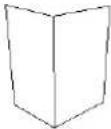 |
| 2Right | |||||||
| (11-660-32)26 3⁄4"MIDDLEUPPERCROSSBARMm | 2 | 4 | [TYBX] | (11-698)38"x25 1⁄2"MIDDLE LOWER ROOF PANELYy | 1 | 4 |  |
| (11-659-32)17 1⁄2"LEFT UPPERCROSSBAR,14' SIDENn | 2 | 2 |  | (11-705)CURTAIN HOOKS | 3 | 104 | |
| (11-661-32)17 1⁄2"RIGHT UPPERCROSSBAR,14' SIDENn-2 | 2 | 2 | [SWW6] | *NOT INCLUDED IN THE BOX | |||
| DESCRIPTION | COLOUR | PART # | |||||
| SPRAY PAINT | SLATE | 18-125 | |||||
| PAINT PEN | 18-126 | ||||||
| 10 mm KEY | 3 | 1 | |||||
43224 GAZEBO
PLAN A LA BASE DES PATTES
PLAN AT BASE OF LEGS

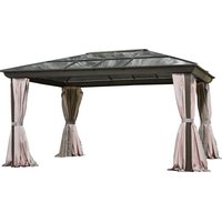
43224 GAZEBO
REBOARD DU TOIT
ROOF OVERHANG
- GAZEBO penguin inc.
- DO NOT DESTROY THE BOXES UNTIL COMPLETELY ASSEMBLED PLEASE VERIFY THE CONTENT OF EACH BOX AGAINST THE LIST OF PARTS
- DO NOT DESTROY THE BOXES UNTIL COMPLETELY ASSEMBLED
- PLEASE VERIFY THE CONTENT OF EACH BOX AGAINST THE LIST OF PARTS
- WARNING:
- PRIOR TO ASSEMBLY:
- ANCHORING INSTRUCTIONS:
- CARE AND MAINTENANCE:
- ROOF PANELS:
- STRUCTURE:
- MAINTENANCE NOTES
- ONE YEAR LIMITED WARRANTY
- CONDITIONS FOR EXERCISING THE WARRANTY
- LIMITATIONS ON THE WARRANTY
- Before You Assemble the Gazebo
- PLEASE DON'T DESTROY BOXES UNTIL COMPLETELY ASSEMBLED
- Tools required (Not Provided)
- Step 1:
- Step 2:
- Step 3:
- Step 4:
- Step 5:
- Step 6:
- Step 7:
- Step 8:
- Step 9:
- Step 10:
- Step 11:
- Step 12:
- Step 13:
- Step 14:
- Step 15:
- IMPORTANT NOTES:
Brand : Gazebo Penguin
Model : 43224-32
Category : Tent