WGR-500 - Router Planet - Free user manual and instructions
Find the device manual for free WGR-500 Planet in PDF.


| Product Type | Industrial Wall-mount Gigabit Router |
| Model | WGR-500 |
| Ports | 4x 10/100/1000BASE-T LAN, 1x 10/100/1000BASE-T WAN |
| Dimensions (W x D x H) | 148 x 24.2 x 134 mm |
| Weight | 487 g |
| Power Supply | Dual 9-48V DC via terminal block or DC jack |
| Power Consumption | Max 4.32 watts (full load) |
| Operating Temperature | -10°C to 60°C |
| Storage Temperature | -20°C to 70°C |
| Humidity | 5% to 95% (non-condensing) |
| Enclosure | IP30 metal case |
| Installation | Wall-mount, magnetic, or DIN-rail |
| ESD Protection | 6KV DC |
| Router/Switch Mode | Selectable via DIP switch |
| Routing Protocols | Static, RIPv1/v2 |
| Security Features | DoS prevention, 802.1Q VLAN, IP/MAC/Port/URL filtering, DMZ, Port Forwarding |
| Management | Web GUI, SNMP v1/v2c, NTP, syslog, PLANET Smart Discovery Utility |
| IPv6 Support | Yes, including 6to4 tunneling |
| NAT | Yes, with HW NAT acceleration |
| Quality of Service (QoS) | Bandwidth control and prioritization |
| DDNS | PLANET DDNS, DynDNS, TZO |
| Maintenance & Cleaning | Use a dry cloth; do not use liquids or aerosols. Ensure power is off before cleaning. |
| Spare Parts & Repairability | No user-serviceable parts. Contact dealer for repairs. |
Frequently Asked Questions - WGR-500 Planet
User questions about WGR-500 Planet
0 question about this device. Answer the ones you know or ask your own.
Ask a new question about this device
Download the instructions for your Router in PDF format for free! Find your manual WGR-500 - Planet and take your electronic device back in hand. On this page are published all the documents necessary for the use of your device. WGR-500 by Planet.
USER MANUAL WGR-500 Planet
Industrial Wall-mount Gigabit Router
WGR-500
natural_image
Man in white shirt using laptop in server rack (no visible text or symbols)Trademarks
Copyright © PLANET Technology Corp. 2019.
Contents are subject to revision without prior notice.
PLANET is a registered trademark of PLANET Technology Corp. All other trademarks belong to their respective owners.
Disclaimer
PLANET Technology does not warrant that the hardware will work properly in all environments and applications, and makes no warranty and representation, either implied or expressed, with respect to the quality, performance, merchantability, or fitness for a particular purpose. PLANET has made every effort to ensure that this User's Manual is accurate; PLANET disclaims liability for any inaccuracies or omissions that may have occurred.
Information in this User's Manual is subject to change without notice and does not represent a commitment on the part of PLANET. PLANET assumes no responsibility for any inaccuracies that may be contained in this User's Manual. PLANET makes no commitment to update or keep current the information in this User's Manual, and reserves the right to make improvements to this User's Manual and/or to the products described in this User's Manual, at any time without notice.
If you find information in this manual that is incorrect, misleading, or incomplete, we would appreciate your comments and suggestions.
FCC Warning
This equipment has been tested and found to comply with the limits for a Class A digital device, pursuant to Part 15 of the FCC Rules. These limits are designed to provide reasonable protection against harmful interference when the equipment is operated in a commercial environment. This equipment generates, uses, and can radiate radio frequency energy and, if not installed and used in accordance with the Instruction manual, may cause harmful interference to radio communications. Operation of this equipment in a residential area is likely to cause harmful interference in which case the user will be required to correct the interference at his own expense.
CE Mark Warning
This is a Class A product. In a domestic environment, this product may cause radio interference, in which case the user may be required to take adequate measures.
WEEE Warning
To avoid the potential effects on the environment and human health as a result of the presence of hazardous substances in electrical and electronic equipment, end users of electrical and electronic equipment should understand the meaning of the crossed-out wheeled bin symbol. Do not dispose of WEEE as unsorted municipal waste and have to collect such WEEE separately.
Revision
User's Manual of PLANET WGR-500
Model: WGR-500
Revision: 1.0 (September, 2019)
Part No: EM-WGR-500_v1.0
TABLE OF CONTENTS
Chapter 1. Introduction......5
1.1. Packet Contents....5
1.2. Product Description....6
Compact and Cost-effective for Building Industrial IoT Networks....6
Dual Power Input for High Availability Network System....9
1.3. Product Features....10
1.4. Product Specifications.... 11
Chapter 2. Hardware Installation....13
2.1 Product Outlook....13
2.1.1 Front and Bottom Panel....13
2.1.2 LED Indications....16
2.1.3 Wiring the Power Inputs....18
2.2 Installing the industrial wall-mount Gigabit router 20
2.2.1 Wall-mount Installation....20
2.2.2 Magnet Installation....22
2.2.3 DIN-rail Installation....22
Chapter 3. Router Management ......25
3.1 Requirements....25
3.2 Web Management....26
Chapter 4. Configuration in Web UI....28
4.1 Main Web Page....28
4.2 System....31
4.2.1 Dashboard 32
4.2.2 Setup Wizard 34
4.2.3 Status....41
4.2.4 Stastics 41
4.2.5 Operation Mode 42
4.2.6 Date and Time....44
4.2.7 User Configuration 45
4.2.8 SNMP 46
4.2.9 Log....47
4.3 Network 48
4.3.1 WAN Setup 49
4.3.2 LAN Setup....52
4.3.3 VLAN....53
4.3.4 Route 54
4.3.5 DDNS....56
4.3.6 IPv6 WAN Setting 58
4.3.7 IPv6 LAN Setting....59
4.3.8 RADVD 60
4.3.9 Tunnel (6 over 4)....63
4.4 Security....64
4.4.1 QoS....65
4.4.2 DoS....67
4.4.3 Port Filtering....69
4.4.4 IP Filtering....70
4.4.5 MAC Filtering 71
4.4.6 URL Filtering 72
4.4.7 DMZ 73
4.4.8 Port Forwarding 74
4.5 Maintenance....75
4.5.1 Connection Test 76
4.5.2 Save/Restore Configuration....77
4.5.3 Upgrading Firmware 78
4.5.4 Reboot 78
Appendix A: Troubleshooting 79
Appendix B: Planet Smart Discovery Utility 80
Appendix C: Planet DDNS 81
Appendix D: Glossary 83
Chapter 1. Introduction
The descriptions of PLANET industrial wall-mount Gigabit router series, such as WGR-500, WGR-500-4PV and WGR-5010-4P, are as follows:
| WGR-500 | Industrial Wall-mount Gigabit: Router with 5-Port 10/100/1000T |
| WGR-500-4P | Industrial Wall-mount Gigabit: Router with 4-Port 802.3at PoE+ |
| WGR-500-4PV | Industrial Wall-mount Gigabit: Router with 4-Port 802.3at PoE+ and LCD Touch Screen |
| Model Name | 10/100/1000TCopper Port s | 802.3at PoE +Ports | 2.4" LCD U | SB Port |
| WGR-500 | 5 | - | - | - |
| WGR-500-4P | 5 | 4 | - | ■ |
| WGR-500-4PV | 5 | 4 | ■ | ■ |
1.1. Packet Contents
Open the box of the industrial wall-mount Gigabit router and carefully unpack it. The box should contain the following items:
| Industrial Router x 1 | Quick Installation Guide x 1 | Wall-mounted Kit x 1 |
 |  |  |
| DIN-rail Kit x 1 | Magnet Kit x 1 | 2-pin Terminal Block Connector x 1 |
 |  |  |
| RJ45 Dust Cap x 5 | ||
 | ||
If any of these are missing or damaged, please contact your dealer immediately; if possible, retain the carton including the original packing material, and use them again to repack the product in case there is a need to return it to us for repair.
1.2. Product Descript on
Compact and Cost-effective for Building Industrial IoT Networks
PLANET WGR-500 is an industrial router designed for such Internet of Things (IoT) networks as industry, transportation, government, agriculture and other public areas. Its compact size and redundant power design are perfect for any network environment and stable operation.
The WGR-500, the best solution for any industry router application, features the following special management and operation functions:
■ Setup Wizard design and IPv6 / IPv4 support
■ Router and switch working mode
■ Firewall with 802.1Q VLAN security
■ HW NAT accelerates internet NAT routing performance
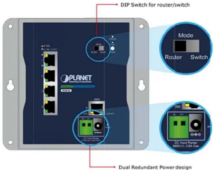
■ 9-48V DC redundant power design
IPv6 Support for IoT Networking
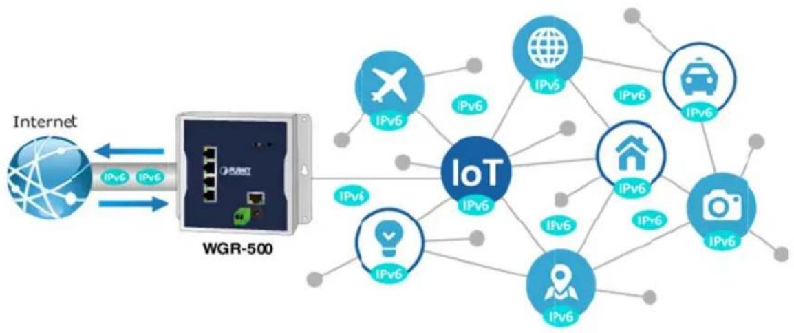
With billions of new IoT devices entering the market each year, IPv4 is fixed with the issue of not being able to fulfill the requirements of connecting all the IoT products together. IPv6 offers a highly scalable address scheme that provides a unique 64-bit host ID to every present and future IoT device. It is sufficient to address the needs of any present and future communication device. That means IPv6 allows IoT products to be uniquely a addressable without having to work around all of the traditional NAT and firewall issues.
The WGR-500 supports both IPv6 and IPv4 to ensure industrial Ethernet with a smooth migration path from the IPv4-based networks to the full IPv6 infrastructure. It assigns IPv6 addresses to clients and passes the IPv6 traffics through the IPv4 environment. The WGR-500 supports IPv4 tunneling (6to4 transition tunnel) implementations for IoT connectivity.
flowchart
graph LR
    A["Internet"] -->|IPv6| B["WGR-500"]
    B --> C["IoT"]
    C --> D["IPv6"]
    C --> E["IPv5"]
    C --> F["IPv6"]
    C --> G["IPv6"]
    C --> H["IPv6"]
    C --> I["IPv6"]
    C --> J["IPv6"]
    C --> K["IPv6"]
    C --> L["IPv6"]
    C --> M["IPv6"]
    C --> N["IPv6"]
    C --> O["IPv6"]
    C --> P["IPv6"]
    C --> Q["IPv6"]
    C --> R["IPv6"]
    C --> S["IPv6"]
    C --> T["IPv6"]
    C --> U["IPv6"]
    C --> V["IPv6"]
    C --> W["IPv6"]
    C --> X["IPv6"]
    C --> Y["IPv6"]
    C --> Z["IPv6"]
    C --> AA["IPv6"]
    C --> AB["IPv6"]
    C --> AC["IPv6"]
    C --> AD["IPv6"]
    C --> AE["IPv6"]
    C --> AF["IPv6"]
    C --> AG["IPv6"]
    C --> AH["IPv6"]
    C --> AI["IPv6"]
    C --> AJ["IPv6"]
    C --> AK["IPv6"]
    C --> AL["IPv6"]
    C --> AM["IPv6"]
    C --> AN["IPv6"]
    C --> AO["IPv6"]
    C --> AP["IPv6"]
    C --> AQ["IPv6"]
    C --> AR["IPv6"]
    C --> AS["IPv6"]
    C --> AT["IPv6"]
    C --> AU["IPv6"]
    C --> AV["IPv6"]
    C --> AW["IPv6"]
    C --> AX["IPv6"]
    C --> AY["IPv6"]
    C --> AZ["IPv6"]
    C --> BA["IPv6"]
    C --> BB["IPv6"]
    C --> BC["IPv6"]
    C --> BD["IPv6"]
    C --> BE["IPv6"]
    C --> BF["IPv6"]
    C --> BG["IPv6"]
    C --> BH["IPv6"]
    C --> BI["IPv6"]
    C --> BJ["IPv6"]
    C --> BK["IPv6"]
    C --> BL["IPv6"]
    C --> BM["IPv6"]
    C --> BN["IPv6"]
    C --> BO["IPv6"]
    C --> BP["IPv6"]
    C --> BQ["IPv6"]
    C --> BR["IPv6"]
    C --> BS["IPv6"]
    C --> BT["IPv6"]
    C --> BU["IPv6"]
    C --> BV["IPv6"]
    C --> BW["IPv6"]
Secure Firewall Protection
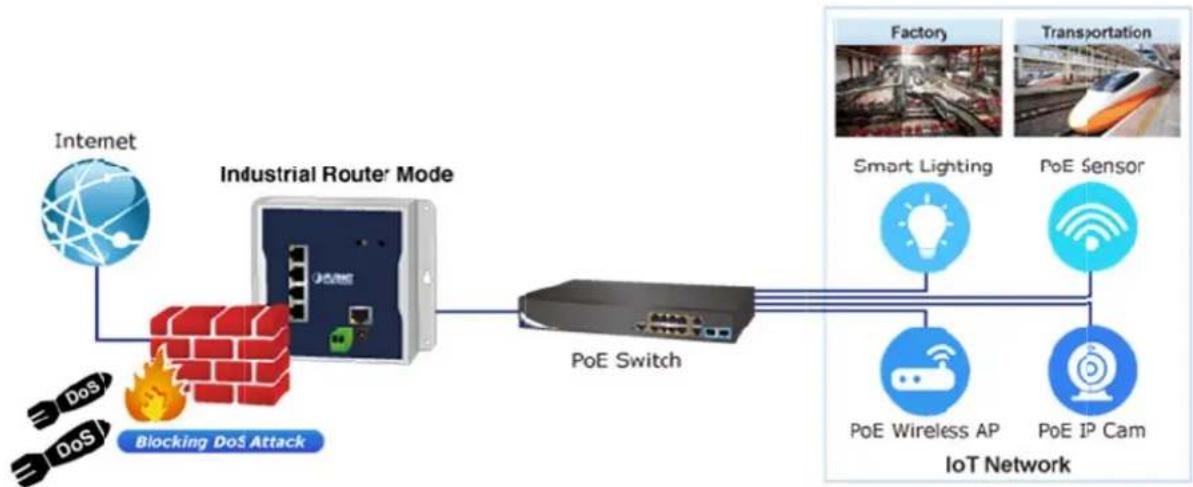
The denial-of-service attacks (DoS) attempt to consume resources and therefore deny users network and application access. There are two types of DoS attacks – SYN floods and ping of death that consume actual server resources, or those of inter mediate communication equipment, such as firewalls and load balancers, and the other, volume-based attacks like UDP/ICMP floods and other spoofed-packet floods that would saturate the bandwidth of the attacked site.
The WGR-500 provides firewall to protect IoT devices against networking attack like denial-of-service (DoS), and emerging malicious traffic before attacks can occur. With fire wall protection, it prevents IoT network from threats and keeps networking more secure.
flowchart
graph LR
    A["Internet"] --> B["Industrial Router Mode"]
    C["DoS"] --> B
    D["DoS"] --> B
    B --> E["PoE Switch"]
    E --> F["IoT Network"]
    G["Factory"] --> H["Smart Lighting"]
    I["Transportation"] --> J["PoE Sensor"]
    K["PoE Wireless AP"] --> L["PoE IP Cam"]
    M["Blocking DoS Attack"] --> B
VLAN Support for Isolated Traffic and Security
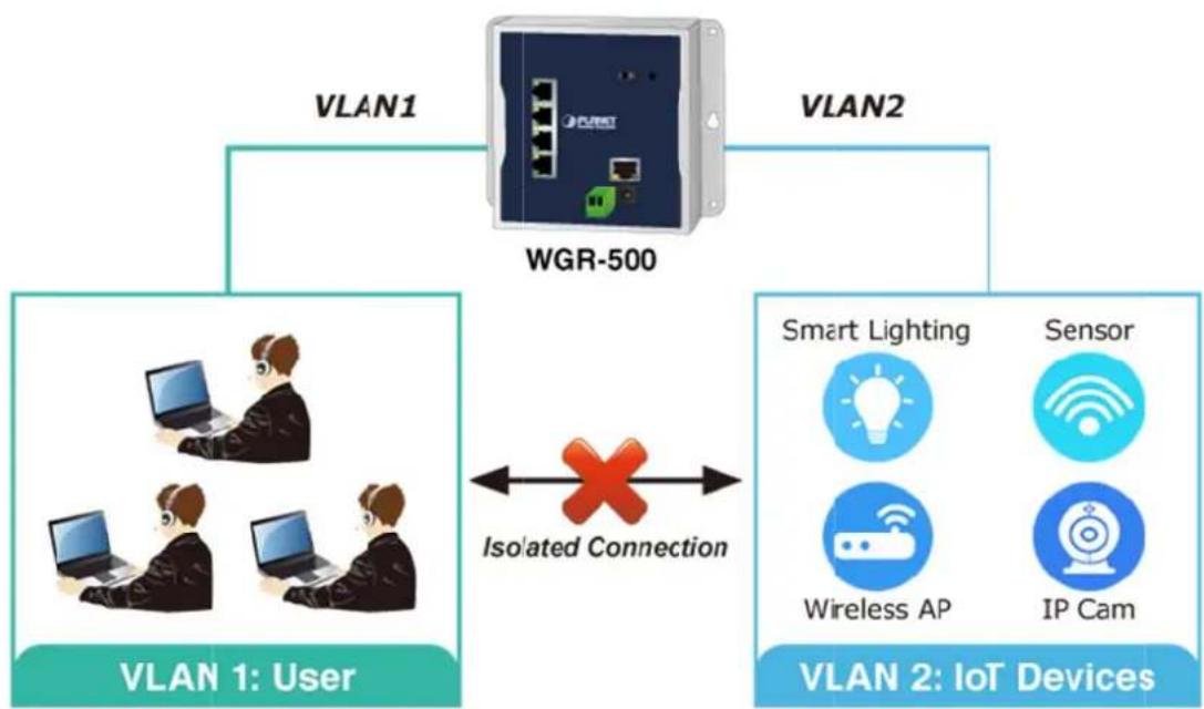
Virtual LANs (VLANs) offer the logical grouping technique to separate the physical ports off Ethernet switch. It can separate private network into several parts for different users. If there are too many computers or networking devices in the same network segment, it will result in heavy traffics locally. Besides, VLANs provide enhanced network security that network administrators can control over each port and whatever resources it is allowed to use.
The WGR-500 supports 802.1Q VLAN to separate traffic of users and IoT devices and can work as an intelligent traffic forwarder to control traffic and isolate connections of two groups. It will not only optimize bandwidth but also improve network security.
flowchart
graph TD
    A["VLAN 1: User"] --> B["WGR-500"]
    C["VLAN 2: IoT Devices"] --> B
    B --> D["Smart Lighting"]
    B --> E["Sensor"]
    B --> F["Wireless AP"]
    B --> G["IP Cam"]
    style A fill:#99ccff,stroke:#333
    style C fill:#99ccff,stroke:#333
    style B fill:#e6f7ff,stroke:#333
    linkStyle 0 stroke:#000,stroke-width:2px
    linkStyle 1 stroke:#000,stroke-width:2px
    linkStyle 2 stroke:#000,stroke-width:2px
    linkStyle 3 stroke:#000,stroke-width:2px
    linkStyle 4 stroke:#000,stroke-width:2px
    linkStyle 5 stroke:#000,stroke-width:2px
    linkStyle 6 stroke:#000,stroke-width:2px
    linkStyle 7 stroke:#000,stroke-width:2px
    linkStyle 8 stroke:#000,stroke-width:2px
    linkStyle 9 stroke:#000,stroke-width:2px
    linkStyle 10 stroke:#000,stroke-width:2px
Innovative Wall-mount Installation
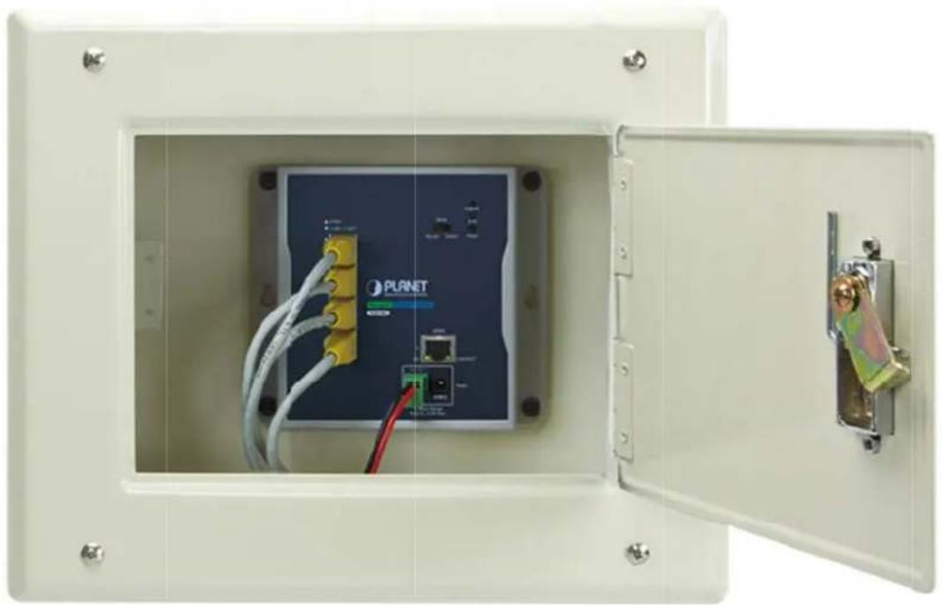
The WGR-500 is specially designed to be installed in a narrow environment, such as wall enclosure. The compact, flat and wall-mounted design fits easily in any space-limited location. It adopts the user-friendly "Front Access"
design, making the installing and cable wirings easy. The WGR-500 can be installed by fixed wall mounting, magnetic wall mounting or DIN rail, thereby making its usability more flexible.
natural_image
Interior view of a white industrial enclosure showing a Planet switch module with wiring and ports, no visible text or symbols.Dual Power Input for High Availability Network System
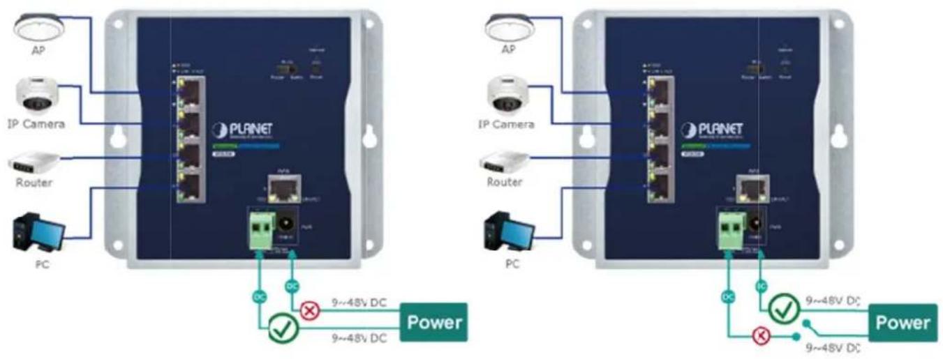
The WGS -500 features a strong dual power input system (9V\~48V DC) incorporated into customer's automation network to enhance system reliability and uptime. In the example below, when the 2-pin terminal block fails to work, the hardware failover function will be activated automatically to keep powering the WGS-500 via the DC plug power alternatively without any loss of operation.
Dual Power Input with Auto Failover
1.3. Product Features
Physical Port
■ Four 10/100/1000BASE-T RJ45 ports
■ One 10/100/1000BASE-T RJ45 WAN port or LAN port (router mode / switch mode)
Industrial Case and Installation
■ Compact size with fixed wall mounting, magnetic wall mounting or DIN-rail design
■ IP30 metal case
■ Supports -10 to 60 degrees C operating temperature
■ Supports ESD 6KV DC Ethernet protection
■ Dual power input design
- 9V\~48V DC wide power input, redundant power with reverse polarity protection
- 2-pin terminal block or DC jack connector
Layer 2 Features
■ Supports IEEE 802.1Q tagged VLAN
■ Supports IEEE 802.1D Spanning Tree Protocol (STP)
Layer 3 IP Routing Features
■ IPv6 support
■ WAN Internet types: Dynamic IP(DHCP Client), static IP, PPPoE, L2TP, PPTP
■ Static and dynamic (RIP1 and 2) routing
■ Supports Port Forwarding, DMZ, and UPnP for various networking applications
■ IP/MAC-based bandwidth control
■ Supports Dynamic DNS and PLANET DDNS
Security
■ Port filtering lets you either allow or prevent which applications can access the Internet.
■ MAC filtering allows you to include or exclude computers and devices based on their MAC address
■ URL filtering allows you to control access to Internet websites in an URL list
■ IP source guard prevents IP spoofing attacks
■ DoS attack prevention
Management
■ Management Interfaces
- Web GUI management
■ Static and DHCP for IP address assignment
■ System Maintenance
- Firmware upload/download via HTTP
- Hardware-based reset button for system reboot or reset to factory default
■ NTP (Network Time Protocol)
■ Event message logging to remote syslog server
■ PLANET Smart Discovery Utility for deployment management
1.4. Product Specifications
| Product WGR-500 | ||
| Hardware Specifications | ||
| Interface | LAN | 4 x 10/100/1000 BASE-T, auto-negotiation, auto MDI/MDI-X RJ45 port |
| WAN | 1 x 10/100/1000 BASE-T, auto-negotiation, auto MDI/MDI-X RJ45 port | |
| DIP Switch For router and switch mode | ||
| Reset Button | < 5 sec: System reboot> 5 sec: Factory default | |
| ESD Protection 6KV DC | ||
| Enclosure IP30 metal case | ||
| Installation DIN-rail or wall mounting | ||
| Connector | Removable 2-pin terminal block for power input- Pin 1/2 for Power (Pin 1: V+ / Pin 2: V-)DC power jack with 2.1mm central pole | |
| LED Indicator | System:Internet (Green)PWR (Green)SYS (Green)Per 10/100/1000T RJ45 Ports:10/100 LNK/ACT (Green)1000 LNK/ACT (Amber) | |
| Dimensions (W x D x H) 148 x 24.2 x 134 mm | ||
| Weight | 487 g | |
| Power Requirements | Dual 9~48V DC | |
| Power Consumption | Max. 1.71 watts/5.84 BTU (Power on without any connection)Max. 4.32 watts/14.75 BTU (Full loading) | |
| Router Features | ||
| Internet Connection Type | Shares data and Internet access for users, supporting the following internet accesses:■ PPPoE■ Static IP■ Dynamic IP | |
| Routing Protocol | Static routingRIPv1/2 | |
| Security | DOS protectionMAC/IP/Port/URL filtering | |
| Protocol / Feature | 802.1Q tag-based VLAN802.1d spanning treeQoS NAT and HW NATPort ForwardingDMZUPnP and PLANET DDNS | |
| System Management | Web-based (HTTP) configurationSNTP time synchronization | |
| System log supports remote logSNMP v1, v2c | ||
| Standards Conformance | ||
| Regulatory Compliance FCC Part 15 Class A, CE | ||
| Stability Testing | IEC60068-2-32 (free fall)IEC60068-2-27 (shock)IEC60068-2-6 (vibration) | |
| Standards Compliance | IEEE 802.3 10BASE-TIEEE 802.3u 100BASE-TX/100BASE-FXIEEE 802.3ab Gigabit 1000TIEEE 802.1D Spanning Tree ProtocolIEEE 802.1p Class of ServiceIEEE 802.1Q VLAN taggingRFC 768 UDPRFC 793 TFTPRFC 791 IPRFC 792 ICMPRFC 2068 HTTP | |
| Environment | ||
| Operating Temperature -10 ~ 60 degrees C | ||
| Storage Temperature -20 ~ 70 degrees C | ||
| Humidity 5 ~ 95% (non-condensing) | ||
Chapter 2. Hardware Installation
This chapter describes the hardware of the industrial wall-mount Gigabit router and gives a physical overview and different installation methods.
2.1 Product Outlook
This section describes the hardware features of the industrial wall-mount Gigabit router. For easier management and control of the industrial wall-mount Gigabit router, familiarize yourself with its display indicators and ports.
2.1.1 Front and Bottom Panel
The front panel provides a simple i nterface monitoring the ind ustrial wall-mount Gigabit router. Figures 2-1 show the front panels of the industrial wall-mount Gigabit routers.
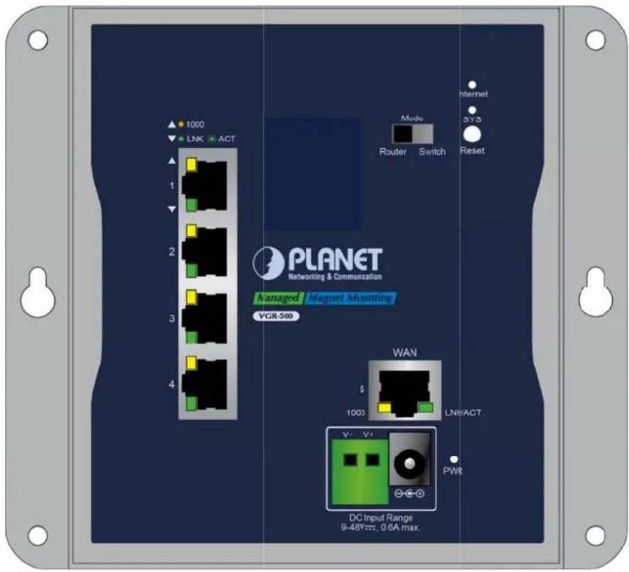
Figure 2-1: Front Panel of WGR-500
■ Res et Button
The bottom of the industrial wall-mount Gigabit router comes with a reset button designed for rebooting system or resetting to factory default. The reset buttons are shown in Figures 2-2 and following is the summary table of reset button functions:
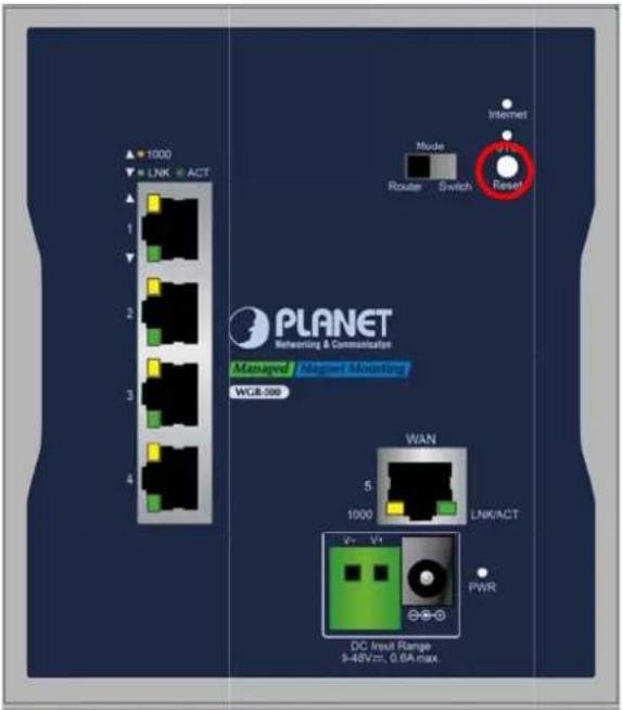
Figure 2-2: Reset Button of WGR-500
| Reset Button Pressed and Released | Functio n |
| < 5 sec: System Reboot | Reboot the system. |
| > 5 sec: Factory Default | Reset t he system to factory d efault. The industrial wall-mount Gigabit router will then reboot and load the default settings as shown below:De fault Username: adminDe fault Password: adminDe fault IP Address: 192.168.1.1Su b net Mask: 255.255.255.0De fault Gateway: 192.168.1.254 |
DIP Switch
Only the WGR-500 has the DIP switch, which is for selecting an operation mode. The DIP switch is shown in Figure 2-3.
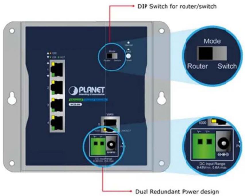
Figure 2-3: DIP Switch of WGR-500
2.1.2 LED Indications
The LED indicators of the WGR-500 are shown in Figures 2-4.
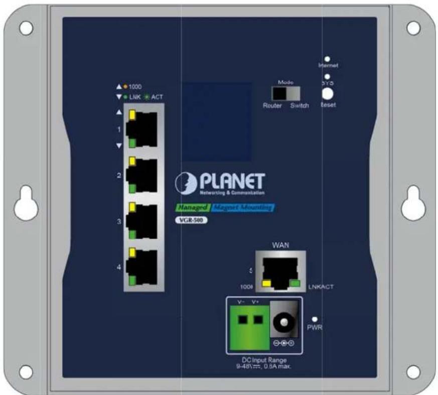
Figure 2-4: LED Indicators of WGR-500
■ Sys tem
| LED | Color | Function |
| Internet | Green | Internet is synchronized successfully in the route mode. |
| Blink | Internet data is being transmitted. | |
| PWR | Green | Lights to indicate that the Switch has power. |
| SYS | Green | Lights to indicate the system is working. |
■ LAN Per 10/100/1000Mbps RJ45 Port (Port-1 to Port-4)
| LED Color | Function | ||
| LNK/ACT | Green | Lights: | To indicate the link through that port is successfully established at 10/100Mbps. |
| Blinks: | To indicate that the switch is actively sending or receiving data over that port. | ||
| LNK/ACT | Am ber | Lights:Blinks: | To indicate the link though that port is successfully established at 1000 Mbps.To indicate that the switch is actively sending or receiving data over that port. |
■ WAN Per 10/100/1000Mbps RJ45 Port (Port-5)
| LED Color Function | |||
| LNK/ACT | Green | Lights: | To indicate the link through that port is successfully established at 10/100Mbps. |
| Blinks: | To indicate that the switch is actively sending or receiving data over that port. | ||
| LNK/ACT | Amber | Lights: | To indicate the link through that port is successfully established at 1000 Mbps. |
| Blinks: | To indicate that the switch is actively sending or receiving data over that port. | ||
2.1.3 Wiring the Power Inputs
The industrial wall-mount Gigabit router features a strong dual power input system (Terminal block and DC jack) incorporated into customer's automation network to enhance system reliability and uptime. The dual power design is shown in Figure 2-5.
| Model\Power Input Range | 2-pin | Terminal Block | DC Jack |
| WGR-500 | 9~48V DC | 9~48V DC | |
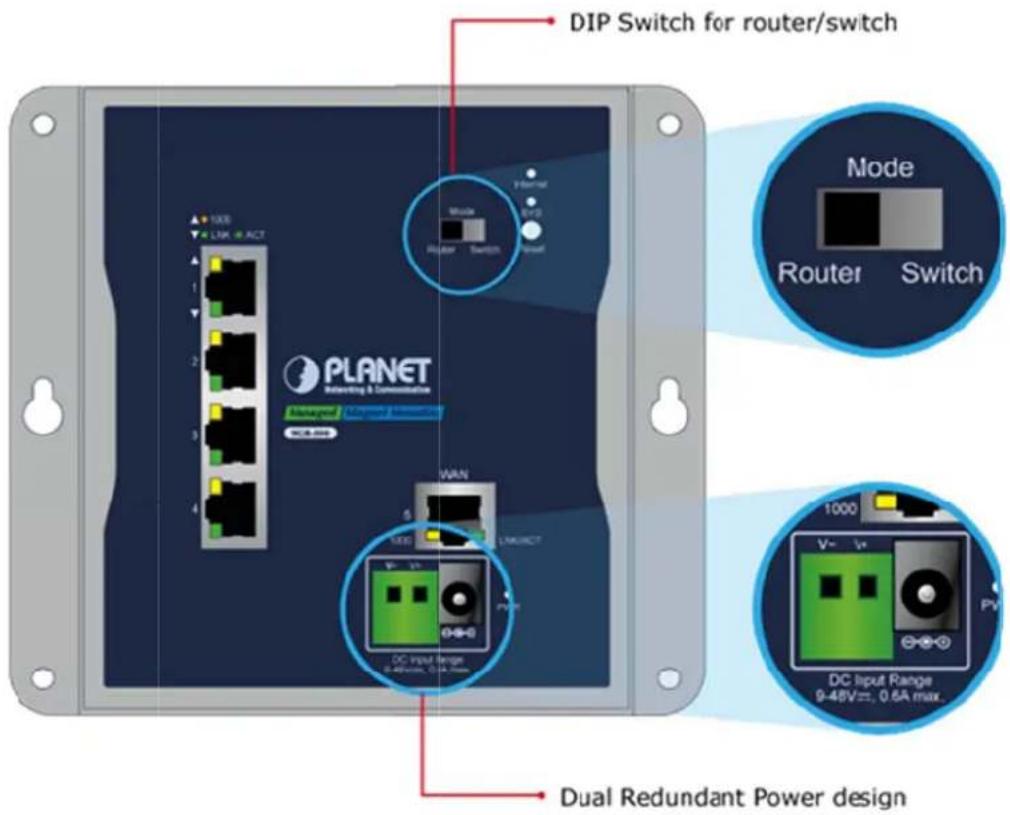
Figure 2-5: Dual Power Design of WGR-500
■ Ter minal Block Connector Pinout
To install the 2-pin Terminal Block Connector on the industrial wall-mount Gigabit router, simply follow the following steps:
Step 1: Insert positive DC power wire into V+, negative DC power wire into V-, as shown in Figure 2-6.

Figure 2-6: Terminal Block Connector
Step 2: Tighten the wire-clamp screws for preventing the wires from loosening and plug them into the industrial wall-mount Gigabit router

- The wire gauge for the terminal block should be in the range of 12 \~ 24 AWG.
- When performing any of the procedures like inserting the wires or tightening the wire-clamp screws, make sure the power is OFF to prevent from getting an electric shock.
DC Power Jack
The WGR-500 comes with DC 9V\~18V power input. The DC power jack is shown in Fig ure 2-7. If you have the issue of power connection, please contact your local sales representative.

2.1mm
DC Receptacle 2.1mm
+9\~48V for each slot

DC receptacle is 2.1mm wide that conforms to the WGR-500 series 2.1mm DC jack's central post. Do not install any improper unit.
Figure 2-7: DC Power Jack
2.2 Installing the industrial wall-mount Gigabit router
This section describes how to install your industrial wall-mount Gigabit router and make connections. Please read the following sections and perform the procedures in the order being presented.
2.2.1 Wall-mot Installation
To install the industrial wall-mount Gigabit router on the wall, simply follow the following steps:
Step 1: There are 4 holes with 8mmdiameter on the wall mount bracket of the Industrial wall-mount Gigabit router as shown in Figure 2-8. The distance between the 2 holes is 133mm of WGR-50, and the line through them must be horizontal.
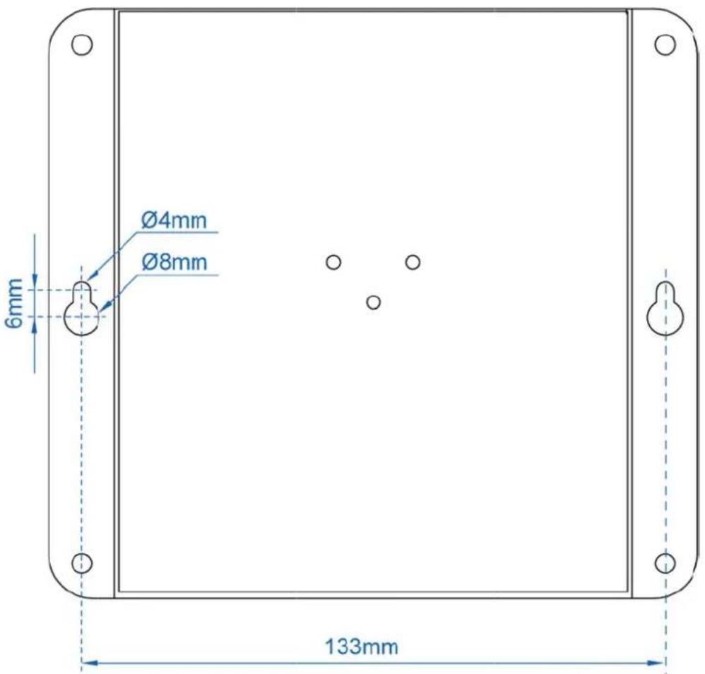
Figure 2-8: Getting Mounting Holes Aligned
Step 2: Install a conductor pipe inside the board hole and flush the edge of the conductor pipe with the wall surface.
Step 3-1: Screw the bolts into the conductor pipe. The industrial wall-mount Gigabit router is between bolts and conductor pipe as shown in Figure 2-9.

This following pictures show the user how to install the device, and the device is not WGR-500.
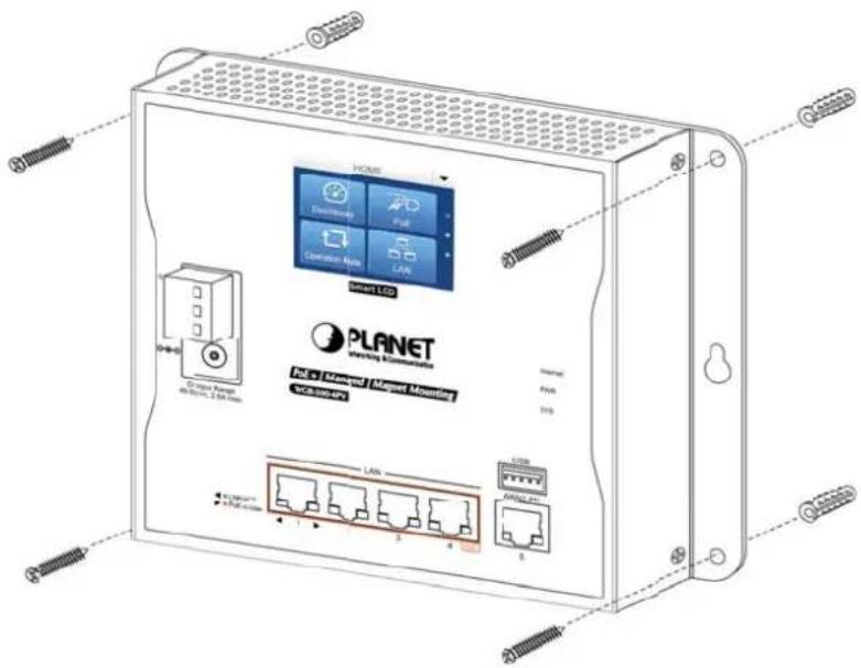
Figure 2-9: Router is screwed to the wall
Step 3-2: Insert screws into the wall anchors, leaving 2mm of each screw exposed. Place the wall-mount slots over the screws and slide the devicedown until the screws fit snugly into the wall-mount slots. The industry router can be hung on the wall as shown in Figure 2-10.
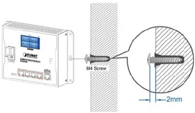
Figure 2-1(0) Wall mounting of router
2.2.2 Magnet Installation
To install the industrial wall-mount Gigabit router on a magnetic surface, simply follow Figure 2-11 below:
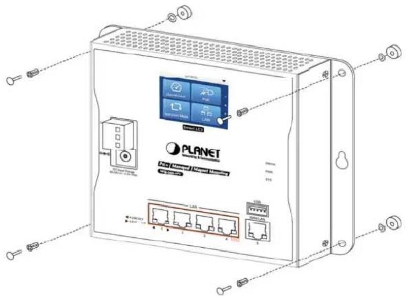
Figure 2-11: Magnetically installed router
2.2.3 DIN-rail Installation
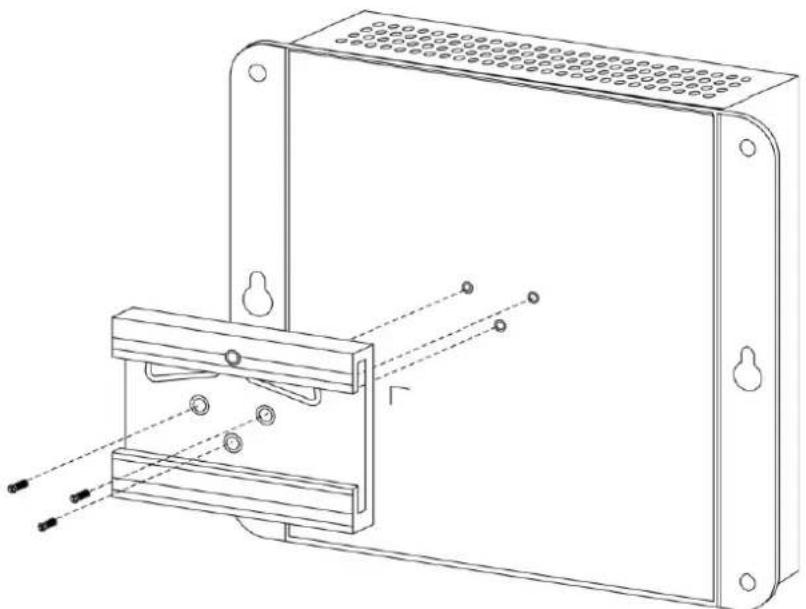
The DIN-rail kit is included in the package. When the wall-mount application for the indu strial wall-mount Gigabit router needs to be replaced with DIN-rail application, please refer to the following figures to screw the DIN-rail on the industrial wall-mount Gigabit router. To hang up the industrial wall-mount Gigabit router, follow the steps below:
Step 1: Screw the DIN-rail bracket on the Industrial Router as shown in Figure 2-12.
natural_image
Technical line drawing of a mechanical assembly with mounting flanges and a bracket (no text or symbols)Figure 2-12: Attaching DIN-rail bracket to router
Step 2: Lightly insert the DIN-rail bracket into the track as shown in Figure 2-13.
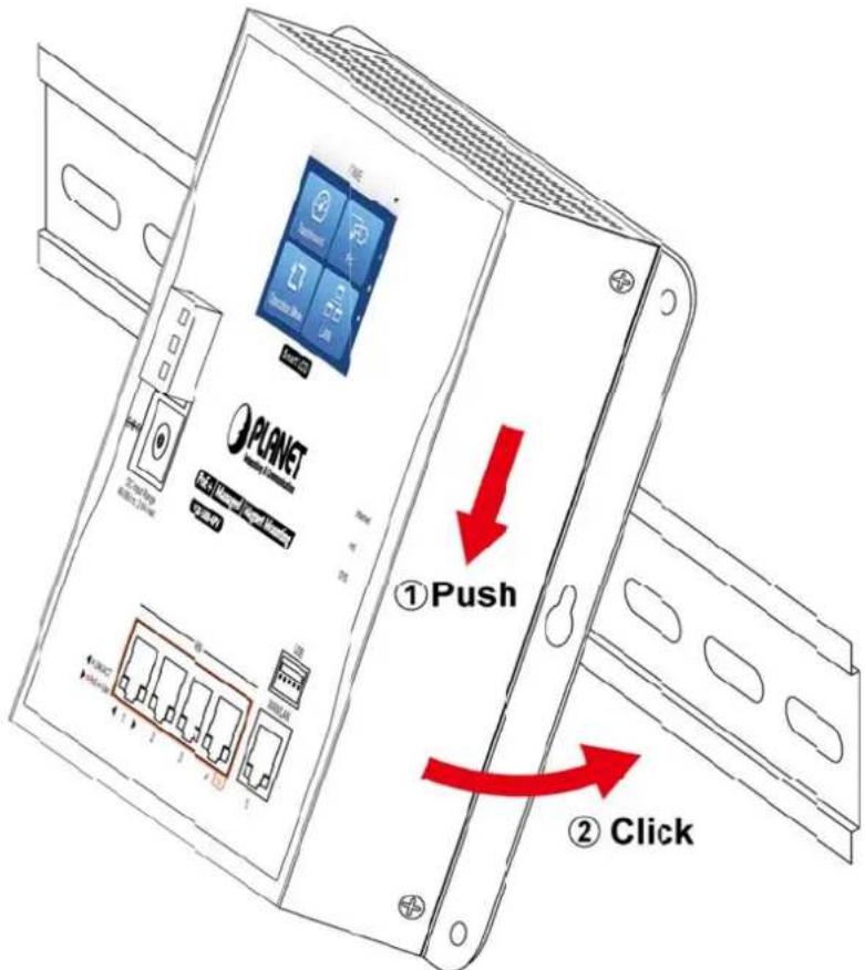
Figure 2-13: Router is placed on the track
Step 3: Router is placed on the track as shown in Figure 2-14
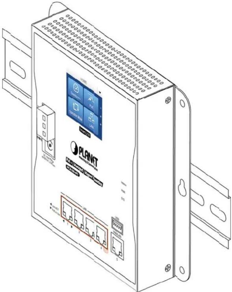
Figure 2-14: Router is tightly fixed on the track
Chapter 3. Router Management
This chapter explains the methods that you can use to configure management access to the industrial wall-mount Gigabit router. It describes the types of management applications and the communication and management protocols that deliver data between your management device (workstation or personal computer) and the system. It also contains information about port connection options.
This chapter covers the following topics:
- Requirements
■ Web Management Access
3.1 Requirements
■ Workstation running Windows XP/2003, Vista, Windows 7/8/10, MAC OS X, Linux, Fedora, Ubuntu or other platform is compatible with TCP/IP protocols.
■ Workstation is installed with Ethernet NIC (Network Interface Card)
■ Ethernet Port
• Network cables -- Use standard network (UTP) cables with RJ45 connectors.
■ The above workstation is installed with Web browser and JAVA runtime environment Plug-in

It is recommended to use Internet Explorer 8.0 or above to access industrial wall-mount Gigabit router.
3.2 Web Management
The industrial wall-mount Gigabit router offers management features that allow users to manage the industrial wall-mount Gigabit router from anywhere on the network through a standard browser such as Microsoft Internet Explorer. After you set up your IP address for the industrial wall-mount Gigabit router, you can access the industrial wall-mount Gigabit router's Web interface applications directly in your Web browser by entering the IP address of the industrial wall-mount Gigabit router.
The following shows how to start up the Web Management of the Industrial wall-mount Gigabit router. Note the Industrial Router is configured through an Ethernet connection. Please make sure the manager PC must be set to the same IP subnet address. For example, the default IP address of the Industrial Router is 192.168.1.1, then the manager PC should be set to 192.168.1.x (where x is a number between 1 and 254) and the default subnet mask is 255.255.255.0 as shown in Figure 3-1.
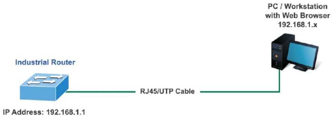
flowchart
graph LR
    A["Industrial Router"] -->|IP Address: 192.168.1.1| B["RJ45/UTP Cable"]
    B --> C["PC / Workstation with Web Browser 192.168.1.x"]
Figure 3-1: Web Management
You can then use your Web browser to list and manage the industrial wall-mount Gigabit router configuration parameters from one central location; the Web Management requires Microsoft Internet Explorer 8.0 or later.
- Use Internet Explorer 8.0 or above Web browser and enter IP address http://192.168.1.1 to access the Web interface.
- When the following dialog box appears, please enter "admin" in both the default user name and password fields. The login screen shown in Figure 3-2 appears.
Default IP Address: 192.168.1.1
Default Username: admin
Default Password: admin
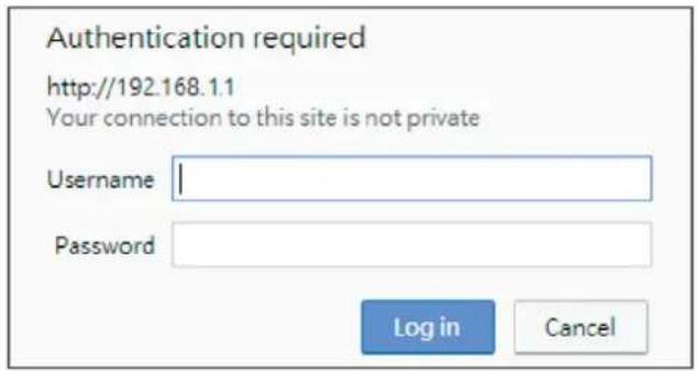
Figure 3-2: Web login Screen
After successfully logging into the web UI of the WGR-500 Series, you will see the main menus on the menu bar and sub menus on the left side. The Figure 3-3 is the web main page of the WGR-500.
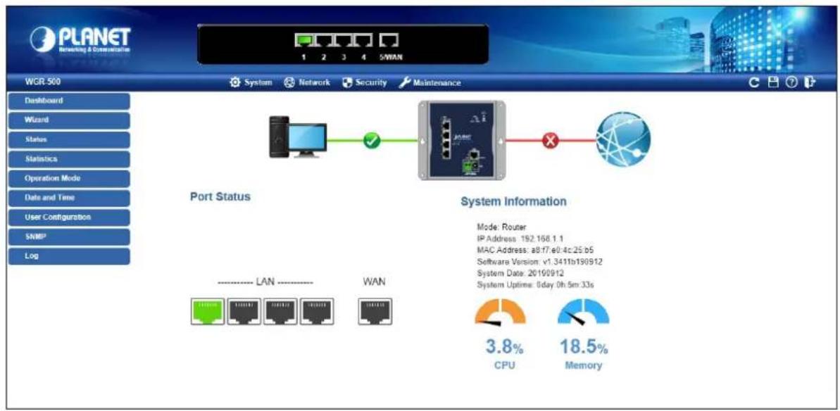
Figure 3-3: Web Main Page of WGR-500
Chapter 4. Configuration in Web UI
This chapter describes how to use Web-based browser interface for configuring and managing industrial wall-mount Gigabit router.
4.1 Main Web Page
After a successful login, the main web page appears. The web main page shown in Figure 4-1 displays the web panel, main menu, function menu, and the main information in the center.
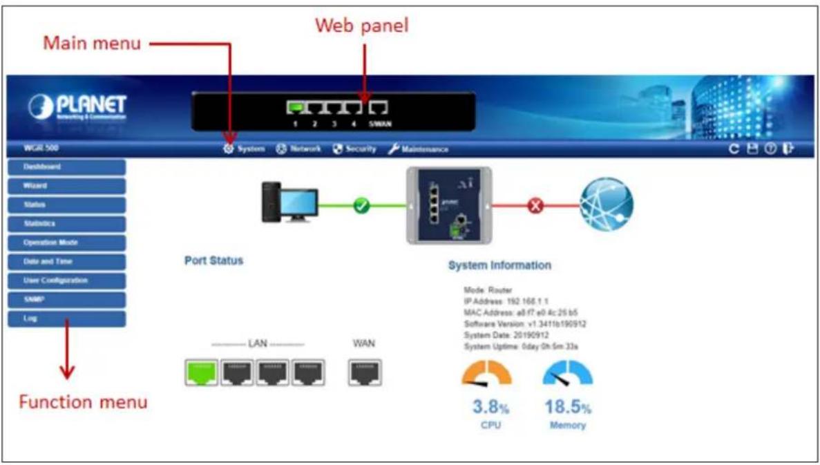
Figure 4-1: Web Main Page
Web Panel
The web panel displays an image of the industrial wall-mount Gigabit router's ports as shown in Figure 4-2.

Figure 4-2: Web Panel
| Object Icon | Function | |
| LAN |  | To indicate the LAN with the RJ45 plug-in. |
 | To indicates network data is sending or receiving |
Main Menu
The main menu displays the product name, function menu, and main information in the center. Via the Web management, the administrator can set up the industrial wall-mount Gigabit router by selecting the functions those listed in the function menu and button as shown in Figures 4-3 and 4-4.

Figure 4-3: Function Menu
| Object Description | |
| System | Provides System information of industrial wall-mount Gigabit router. |
| Network | Provides WAN, LAN and network configuration of industrial wall-mount Gigabit router. |
| Security | Provides QoS and security configuration of industrial wall-mount Gigabit router. |
| Maintenance | Provides firmware upgrade and setting file restore/backup configuration of industrial wall-mount Gigabit router |

Figure 4-4: Function Button
| Object Description | |
 | Click the "Refresh button" to refresh the current Web page. |
 | Click the "Save/Restore configuration button" to go to Save/Restore configuration page. |
 | Click the "Help button" to show the function descriptions of the current pages. |
 | Click the "Logout button" to log out the web UI of the industrial wall-mount Gigabit router. |
4.2 System
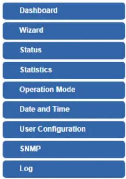
Use the System menu items to display and configure basic administrative details of the industrial wall-mount Gigabit router. The System menu shown in Figure 4-5 provides the following features to configure and monitor system.
flowchart
graph TD
    A["Dashboard"] --> B["Wizard"]
    B --> C["Status"]
    C --> D["Statistics"]
    D --> E["Operation Mode"]
    E --> F["Date and Time"]
    F --> G["User Configuration"]
    G --> H["SNMP"]
    H --> I["Log"]
Figure 4-5: System Menu
| Object Description | |
| Dashboard | The overview of system information includes connection, port, and system status |
| Wizard | The Wizard will guide the user to configuring the router easily and quickly. |
| Status | Display the status of the system, LAN and WAN. |
| Statistics | Display statistics information of network traffic of LAN and WAN |
| Operation Mode | Display the current operation mode, and users can set different modes to LAN interface. |
| Date and Time | Allow to set system time by manual or synchronize system time from Internet NTP server. |
| User Configuration | Allow to change the username and password of industrial wall-mount Gigabit router. |
| SNMP | Display SNMP system information. |
| Log | Provides the system log setting and information display of industrial wall-mount Gigabit router |
4.2.1 Dashboard
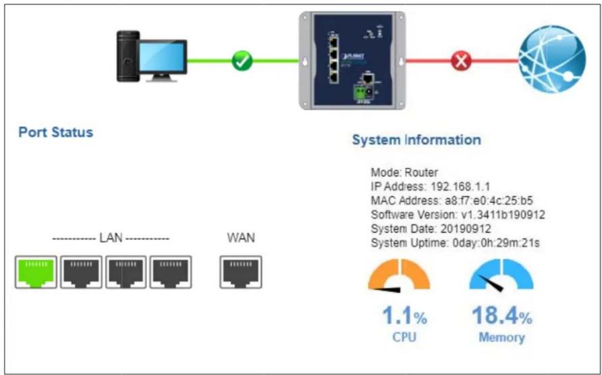
The dashboard provides an overview of system information including connection, port, and system status as shown in Figure 4-6.
flowchart
graph LR
    A["Port Status"] --> B["Network"]
    B --> C["System Information"]
    C --> D["1.1% CPU"]
    C --> E["18.4% Memory"]
Figure 4-6: Dashboard
WAN/LA N Connection Status
| Object | Description |
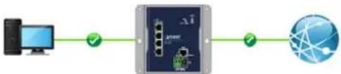 | The status means WAN is connected to Internet and LAN is connected. |
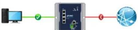 | The status means WAN is disconnected to Internet and LAN is connected. |
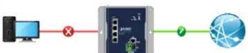 | The status means WAN is connected to Internet and LAN is disconnected. |
Port Stattus
| Object | Description |
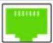 | LAN or WAN port is in use. |
 | LAN or WAN port is not in use. |
System Information
| Object Description | |
| Mode | Display the current operation mode. |
| IP Address | Display the current IP address of industrial wall-mount Gigabit router. |
| MAC Address | Display the LAN MAC address of industrial wall-mount Gigabit router. |
| Software Version | Display the current firmware version of industrial wall-mount Gigabit router. |
| System Date Display the current system date of Industrial wall-mount Gigabit router.The system date will be correct if NTP function is enabled and the Hub is connected to Internet. | |
| System Uptime | Display the period of time the device has been operational. |
| CPU | Display the CPU loading |
| Memory | Display the memory usage |
4.2.2 Setup Wizard
The Wizard will guide the user to configuring industrial wall-mount Gigabit router easily and quickly. There are different procedures in different operation modes. According to the operation mode you switch to, please follow the instructions below to configure industrial wall-mount Gigabit router via Setup Wizard as shown in Figure 4-7.
Setup Wizard
The setup wizard will guide you to configure access point for first time. Please follow the setup wizard step by step.
Welcome to Setup Wizard.
The Wizard will guide you the through following steps. Begin by clicking on Next.
- Setup Operation Mode
- Choose your Time Zone
- Setup LÁN Interface
- Setup WAN Interface
Figure 4-7: Setup Wizard
Step 1: Operation Mode
The router supports two operation modes, Router and Switch, as shown in Figure 4-8.
Operation Mode
You can setup different modes to LAN interface for NAT and bridging function.

Router:
In this mode, the device is supposed to connect to internet via xDSL/Cable/xPON/Fiber Modem. The NAT is enabled and PCs in LAN ports share the same IP to ISP through WAN port. The connection type can be setup in WAN page by using PPPOE, DHCP client, PPTP client, L2TP client or static IP.

Switch:
In this mode, all Ethernet ports are bridged together and NAT function is disabled. All the WAN related function and firewall are not supported.
Figure 4-8: Setup Wizard – Operation Mode
| Object Description | |
| Router | In this mode, the device is supposed to connect to internet via xDSL/Cable/xPON/Fiber modem. The NAT is enabled and PCs in LAN ports share the same IP with ISP through WAN port. The connection type can be set up in WAN page by using PPPOE, DHCP client, PPTP client , L2TP client or static IP. |
| Switch | In this mode, all Ethernet ports are bridged together and NAT function is disabled. All the WAN-related functions and firewall are not supported. |
Step 3: Time Zone Setting
The Time Configuration option allows you to configure, update, and maintain the correct time on the internal system clock. Daylight Saving can also be configured to automatically adjust the time when needed.
The setup is shown in Figure 4-9
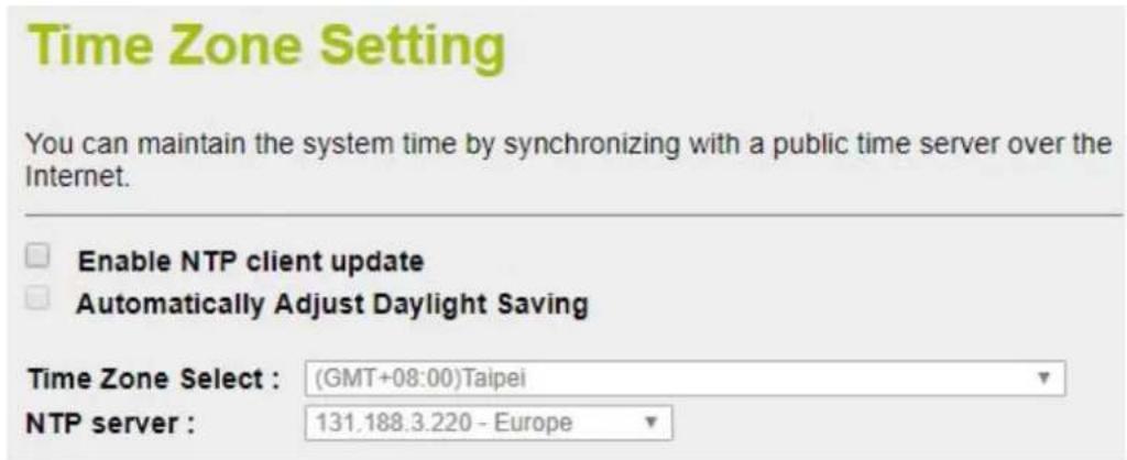
Figure 4-9: Setup Wizard – Time Zone Configuration
| Object Description | |
| Enable NTP client update | Check this box to connect NTP server and synchronize internet time. |
| Automatically Adjust Daylight Savings | Check this box to adjust the daylight savings automatically. |
| Time Zone Select | Select the Time Zone from the drop-down menu. |
| NTP Server | Select the NTP server from the drop-down menu. |
Step 4: LAN Interface Setting
Set up the IP Address and Subnet Mask for the LAN interface as shown in Figure 4-10.
LAN Interface Setup
This page is used to configure the parameters for local area network which connects to the LAN port of your Access Point. Here you may change the setting for IP address, subnet mask, DHCP, etc..
IP Address:
192.168.1.1
Subnet Mask:
255.255.255.0
Figure 4-10: Setup Wizard – LAN Configuration
| Object Description | |
| IP Address | Enter the IP address of your Router. The default: 192.168.1.1 |
| Subnet Mask | An address code that determines the size of the network. Normally use 255.255.255.0 as the subnet mask. |
Step 5 WAN Interface Setting
The industrial wall-mount Gigabit Router supports five access modes in the WAN side as shown in Figure 4-11. Please choose the correct mode according to your ISP.
WAN Interface Setup
This page is used to configure the parameters for Internet network which connects to the WAN port of your Access Point. Here you may change the access method to static IP, DHCP, PPPoE, PPTP or L2TP by click the item value of WAN Access type.
WAN Access Type:
IP Address:
Subnet Mask:
Default Gateway:
DNS :
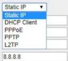
Figure 4-11: Setup Wizard – WAN Configuration
Mode 1 - Static IP
Select Static IP Address if all the Internet port's IP information is provided to you by your ISP. You will need to enter the IP address, subnet mask, gateway address, and DNS address provided to you by your ISP. Each IP address entered in the fields must be in the appropriate IP form, which are four octets separated by a dot (x.x.x.x). The Router will not accept the IP address if it is not in this format. The setup is shown in Figure 4-12.
WAN Interface Setup
This page is used to configure the parameters for Internet network which connects to the WAN port of your Access Point. Here you may change the access method to static IP, DHCP, PPPoE, PPTP or L2TP by click the item value of WAN Access type.
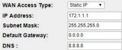
Figure 4-12: WAN Interface Setup – Static IP Setup
| Object Description | |
| IP Address | Enter the IP address assigned by your ISP. |
| Subnet Mask | Enter the Subnet Mask assigned by your ISP. |
| Default Gateway | Enter the Gateway assigned by your ISP. |
| DNS | The DNS server information will be supplied by your ISP. |
Mode 2 DHCP Client
Select DHCP Client to obtain IP Address information automatically from your ISP. The setup is shown in Figure 4-13.
WAN Interface Setup
This page is used to configure the parameters for Internet network which connects to the WAN port of your Access Point. Here you may change the access method to static IP, DHCP, PPPoE, PPTP or L2TP by click the item value of WAN Access type.
WAN Access Type: DHCP Client ▼
Figure 4-13: WAN Interface Setup – DHCP Setup
Mode 3 PPPoE
Choose PPPoE (Point to Point Protocol over Ethernet) if your ISP uses a PPPoE connection. Your ISP will provide you with a username and password. This option is typically used for DSL services. The setup is shown in Figure 4-14.
WAN Interface Setup
This page is used to configure the parameters for Internet network which connects to the WAN port of your Access Point. Here you may change the access method to static IP, DHCP, PPPoE, PPTP or L2TP by click the item value of WAN Access type.
WAN Access Type:
User Name:
Password:
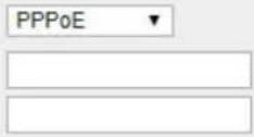
Figure 4-14: WAN Interface Setup – PPPoE Setup
| Object Description | |
| User Name | Enter your PPPoE user name. |
| Password | Enter your PPPoE password. |
Mode 4 PPTP
Choose PPTP (Point-to-Point-Tunneling Protocol) if your ISP uses a PPTP connection. Your ISP will provide you with IP information and PPTP Server IPAddress; of course, it also includes a username and password. This mode is typically used for DSL services. The setup is shown in Figure 4-15.
WAN Interface Setup
This page is used to configure the parameters for Internet network which connects to the WAN port of your Access Point. Here you may change the access method to static IP, DHCP, PPPoE, PPTP or L2TP by click the item value of WAN Access type.
WAN Access Type: PPTP
Dynamic IP (DHCP)
Static IP
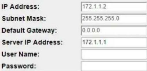
Figure 4-15: WAN Interface Setup – PPTP Setup
| Object Description | |
| IP Address | Enter the IP address. |
| Subnet Mask | Enter the subnet Mask. |
| Server IP Address | Enter the PPTP Server IP address provided by your ISP. |
| User Name | Enter your PPTP username. |
| Password | Enter your PPTP password. |
Mode 5 L2TP
Choose L2TP (Layer 2 Tunneling Protocol) if your ISP uses an L2TP connection. Your ISP will provide you with a username and password. The setup is shown in Figure 4-16.
WAN Interface Setup
This page is used to configure the parameters for Internet network which connects to the WAN port of your Access Point. Here you may change the access method to static IP, DHCP, PPPoE, PPTP or L2TP by click the item value of WAN Access type.
WAN Access Type: L2TP

Dynamic IP (DHCP)

Static IP
| IP Address: | 172.1.1.2 |
| Subnet Mask: | 255.255.255.0 |
| Default Gateway: | 0.0.0.0 |
| Server IP Address: | 172.1.1.1 |
| User Name: | |
| Password: |
Figure 4-16: WAN Interface Setup – L2TP Setup
| Object Description | |
| IP Address Enter the IP address. | |
| Subnet Mask Enter the subnet Mask. | |
| Server IP Address Enter the L2TP Server IP address provided by your ISP. | |
| User Name Enter your L2TP username. | |
| Password Enter your L2TP password. |
4.2.3 Status
This page displays system information of Industrial wall-mount Gigabit router as shown in Figure 4-17.
| System | |
| Uptime | 0day:6h:14m:9s |
| Firmware Version | v1.3411b190912 |
| Build Time | Thu Sep 12 09:17:47 CST 2019 |
| TCP/IP Configuration | |
| Attain IP Protocol | Fixed IP |
| IP Address | 192.168.1.1 |
| Subnet Mask | 255.255.255.0 |
| DHCP Server | Enabled |
| MAC Address | a8:f7:e0:4c:25:b5 |
| WAN Configuration | |
| Attain IP Protocol | Fixed IP Disconnected |
| IP Address | 0.0.0.0 |
| Subnet Mask | 0.0.0.0 |
| Default Gateway | 0.0.0.0 |
| MAC Address | a8:f7:e0:4c:25:b6 |
| LAN IPv6 Configuration | |
| Global Address | |
| LL Address | fe800000000000000aaf7e0fffe4c25b5/64 |
| Default Gateway | fe800000000000000aaf7e0fffe4c25b5/64 |
| MAC Address | a8:f7:e0:4c:25:b5 |
| WAN IPv6 Configuration | |
| Link Type | IP link |
| Connection Type | DHCPv6 |
| Global Address | |
| LL Address | fe800000000000000aaf7e0fffe4c25b6/64 |
| Default Gateway | |
| DNS server | 0000000000000000000000000000000000000000000000000000000000000000000000000000000000000000000000000000 |
| MAC Address | a8:f7:e0:4c:25:b6 |
Figure 4-17: System Information
4.2.4 Stastics
This page displays the number of packet that pass through the router on the WAN and LAN. The statistics are shown in Figure 4-18.
Statistics
This page shows the packet counters for transmission and reception regarding to Ethernet networks.
| Ethernet LAN | Sent Packets | 181650 |
| Received Packets | 87393 | |
| Ethernet WAN | Sent Packets | 0 |
| Received Packets | 0 |
Refresh
Figure 4-18: Statistics
4.2.5 Operation Mode
If you want to set a different mode between router and switch, it can only be configured by DIP switch instead of web GUI.
The industrial wall-mount Gigabit router supports two modes for your application, select the Router mode to act as a Gateway which provides the firewall function to protect your private network. To select the Switch mode, industrial wall-mount Gigabit router will act as a pure 5-Port Ethernet Switch.
The setup is shown in Figure 4-19 and default mode is Router mode.
Operation Mode
You can setup different modes to LAN interface for NAT and bridging function.

Router:
In this mode, the device is supposed to connect to internet via xDSL/Cable/xPON/Fiber Modem. The NAT is enabled and PCs in LAN ports share the same IP to ISP through WAN port. The connection type can be setup in WAN page by using PPPOE, DHCP client, PPTP client, L2TP client or static IP.

Switch:
In this mode, all Ethernet ports are bridged together and NAT function is disabled. All the WAN related function and firewall are not supported.
Figure 4-19: Operation Mode
| Object Description | |
| Router | In this mode, the device is supposed to connect to internet via xDSL/Cable/xPON/Fiber modem. The NAT is enabled and PCs in LAN ports share the same IP with ISP through WAN port. The connection type can be set up in WAN page by using PPPOE, DHCP client, PPTP client , L2TP client or static IP. |
| Switch | In this mode, all Ethernet ports are bridged together and NAT function is disabled. All the WAN related function and firewall are not supported. |
■ The Function Menu of Router Mode
| System Network Security | Maintenance | ||
| Dashboard WAN Setup QoS | Connection Test | ||
| Wizard LAN Setup DoS | Save/Restore Configuration | ||
| Status VLAN Port Filtering | Firmware | ||
| Statistics Route IP Filtering | Reboot | ||
| Operation Mode | DDNS | MAC Filtering | |
| Date and Time | IPv6 WAN Setting | URL Filtering | |
| User Configuration | IPv6 LAN Setting | DMZ | |
| SNMP | Radvd | Port Forwarding | |
| Log | Tunnel (6 over 4) |
■ The Function Menu of Switch Mode
| System Network Maintenance | ||
| Dashboard LAN Setup Connection Test | ||
| Wizard VLAN Save/Restore Configuration | ||
| Status IPv6 LAN Setting | Firmware | |
| Statistics | Reboot | |
| Operation Mode | ||
| Date and Time | ||
| User Configuration | ||
| SNMP | ||
| Log | ||
4.2.6 Date and Time
This section assists you in setting the system time of industrial wall-mount Gigabit router. You can either select to set the time and date manually or automatically obtain the GMT time from Internet as shown in Figure 4-20.
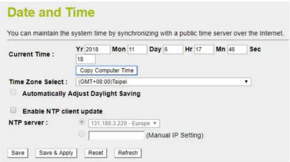
Figure 4-20: Date and Time
| Object Description | |
| Time Zone Select | Input current time manually. |
| Time Zone Select | Select the time zone of the country you are currently in. The router will set its time based on your selection. |
| Enable NTP ClientUpdate | Check to enable NTP update. Once this function is enabled, router will automatically update current time from NTP server. |
| NTP Server | User may select NTP sever or input address of NTP server manually. |
| Save | Press this button to save changes. |
| Save & Apply | Press this button to save and apply changes. |
| Reset | Press this button to undo any changes made locally and revert to previously saved values. |
| Refresh | Press this button to refresh the page |
4.2.7 User Configuration
To ensure the industrial wall-mount Gigabit router's security is secure, you will be asked for your password when you access the industrial wall-mount Gigabit router's Web-based utility. The default user name and password are "admin". This page will allow you to modify the user name and passwords as shown in Figure 4-21.
Password Setup
This page is used to set the account to access the web server. Empty user name and password will disable the protection.
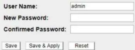
Figure 4-21: User Configuration
| Object Description | |
| User Name | Enter user name. |
| New Password | Input password for this user. |
| Confirmed Password | Confirm password again. |
| Save | Press this button to save changes. |
| Save & Apply | Press this button to save and apply changes. |
| Reset | Press this button to undo any changes made locally and revert to previously saved values. |
4.2.8 SNMP
This section provides SNMP setting of industrial wall-mount Gigabit router as shown in Figure 4-22.
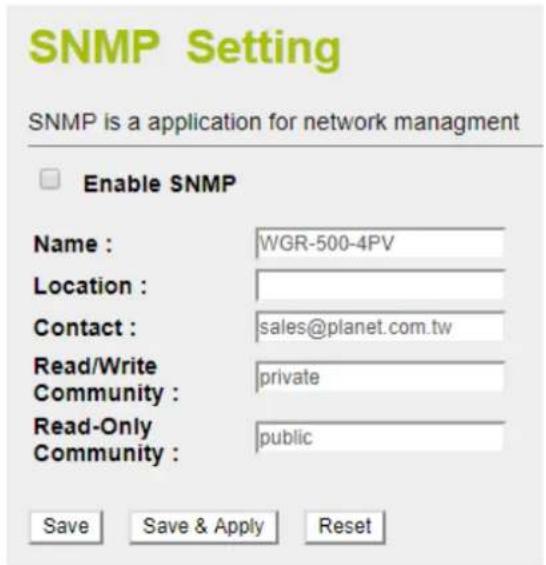
Figure 4-22: SNMP
| Object Description | |
| Enable SNMP | Disable or enable the SNMP function. |
| Name | Allows to enter characters for Name of industrial wall-mount Gigabit router. |
| Location | Allows to enter characters for Location of industrial wall-mount Gigabit router. |
| Contact | Allows to enter characters for contact of industrial wall-mount Gigabit router. |
| Read/Write Community | Allows to enter characters for SNMP Read/Write Community of industrial wall-mount Gigabit router. |
| Read-Only Community | Allow to enter characters for SNMP Read-Only Community of industrial wall-mount Gigabit router. |
| Save | Press this button to save changes. |
| Save & Apply | Press this button to save and apply changes. |
| Reset | Press this button to undo any changes made locally and revert to previously saved values. |
4.2.9 Log
This section will help you to configure the settings of system log as shown in Figure 4-24. You can check the box of the items you want to record it in the log.
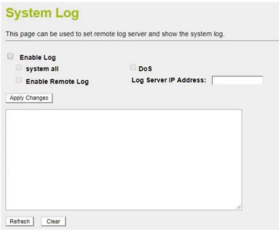
Figure 4-24: Log
| Object Description | |
| Enable Log | Check to enable log function. |
| System all/DoS | Select which log you want to check. Related information will be shown below. |
| Enable Remote Log | Check to enable remote log functionality. |
| Log Server IP Address | Enter Log Server IP Address for remote log. |
| Apply Changes | Press this button to save and apply changes. |
| Refresh | Press this button to refresh the current Web page. |
| Clear | Press this button to clear log information. |
4.3 Network
The Network function provides WAN, LAN and network configuration of industrial wall-mount Gigabit router as shown in Figure 4-25.
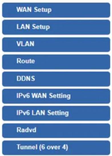
Figure 4-25: Network Menu
| Object Description | |
| WAN Setup | Allows to set WAN interface. |
| LAN Setup | Allows to set LAN interface. |
| VLAN | Allows to set VLAN interface. |
| Route | Allows to set Route interface. |
| DDNS | Allows to set DDNS and PLANET DDNS |
| IPv6 WAN Setting | Allows to set IPv6 WAN interface. |
| IPv6 LAN Setting | Allows to set IPv6 LAN interface. |
| Radvd | Allows to set RADVD |
| Tunnel (6 over 4) | Allows to set Tunnel (6 over 4) |
4.3.1 WAN Setup
This page is used to configure the parameters for Internet network which connects to the WAN port of industrial wall-mount Gigabit router as shown in Figure 4-26. Here you may change the access method to static IP, DHCP, PPPoE, PPTP or L2TP by clicking the item value of WAN Access type.
WAN Interface Setup
This page is used to configure the parameters for Internet network which connects to the WAN port click the item value of WAN Access type.
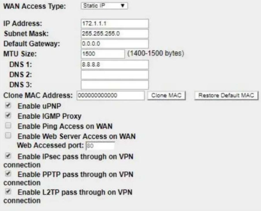
Figure 4-26: WAN Setup
| Object Description | ||
| WAN Access Type | Please select the corresponding WAN Access Type for the Internet, and fill out the correct parameters from your local ISP in the fields which appear below. | |
| Static IP | Select Static IP Address if all the Internet ports’ IP information is provided to you by your ISP (Internet Service Provider). You will need to enter the IP address, subnet mask, gateway address, and DNS address provided to you by your ISP. Each IP address entered in the fields must be in the appropriate IP form, which are four octets separated by a dot (x.x.x.x). The Router will not accept the IP address if it is not in this format.IP AddressEnter the IP address assigned by your ISP.Subnet MaskEnter the Subnet Mask assigned by your ISP.Default GatewayEnter the Gateway assigned by your ISP.DNSThe DNS server information will be supplied by your ISP. | |
| DHCPClient | Select DHCP Client to obtain IP Address information automatically from your ISP. | |
| PPPoE | Choose PPPoE (Point to Point Protocol over Ethernet) if your ISP uses a PPPoE connection. Your ISP will provide you with a username and password. This option is typically used for DSL services.User NameEnter your PPPoE user name.PasswordEnter your PPPoE password. | |
| PPTP | Choose PPTP (Point-to-Point-Tunneling Protocol) if your ISP uses a PPTP connection. Your ISP will provide you with IP information and PPTP Server IP Address; of course, it also includes a username and password. This mode is typically used for DSL services.IP AddressEnter the IP address.Subnet MaskEnter the Subnet Mask.Server IP AddressEnter the PPTP Server IP address provided by your ISP.User NameEnter your PPTP user name.PasswordEnter your PPTP password. | |
| L2TP | Choose L2TP (Layer 2 Tunneling Protocol) if your ISP uses a L2TP connection. Your ISP will provide you with a username and password.IP AddressEnter the IP address.Subnet MaskEnter the Subnet Mask.Server IP AddressEnter the L2TP Server IP address provided by your ISP.User NameEnter your L2TP user name.PasswordEnter your L2TP password. | |
| Host Name | This option specifies the Host Name of the industrial wall-mount Gigabit router. | |
| MTU Size | The normal MTU (Maximum Transmission Unit) value for most Ethernet networks is 1492 Bytes. It is not recommended that you change the default MTU Size unless required by your ISP. | |
| Attain DNS Automatically | Select “Attain DNS Automatically”, the DNS servers will be assigned dynamically from your ISP. | |
| Set DNS Manually | If your ISP gives you one or two DNS addresses, select Set DNS Manually and enter the primary and secondary addresses into the correct fields. | |
| Enable uPnP | Check the box to enable the uPnP function. | |
| Enable IGMP Proxy | Check the box to enable the IGMP Proxy function. | |
| Enable Ping Access on WAN | Check the box to enable Ping access from the Internet Network. | |
| Enable Web Server Access on WAN | Check the box to enable the web server access of the Industrial wall-mount Gigabit router from the Internet network. | |
| Enable IPSec pass through on VPN connection | Check the box to enable IPSec passthrough function on VPN connection. | |
| Enable PPTP passthrough on VPN connection | Check the box to enable PPTP passthrough function on VPN connection. | |
| Enable L2TP passthrough on VPN connection | Check the box to enable L2TP passthrough function on VPN connection. | |
| Enable IPv6 passthrough on VPN connection | Check the box to enable IPv6 passthrough function on VPN connection. | |



If you get Address found to be in error when you access a Web site, it is likely that your DNS servers are set up improperly. You should contact your ISP to get DNS server addresses.

WAN IP, whether obtained automatically or specified manually, should NOT be on the same IP net segment as the LAN IP; otherwise, the router will not work properly. In case of emergency, press the hardware-based "Reset" button.
4.3.2 LAN Setup
This page is used to configure the parameters for local area network which connects to the LAN port of your industrial wall-mount Gigabit router as shown in Figure 4-27. Here you may change the setting for IP address, subnet mask, DHCP, etc.
LAN Interface Setup
This page is used to configure the parameters for local area network which connects to the LAN port of your Access Point. Here you may change the setting for IP address, subnet mask, DHCP, etc..
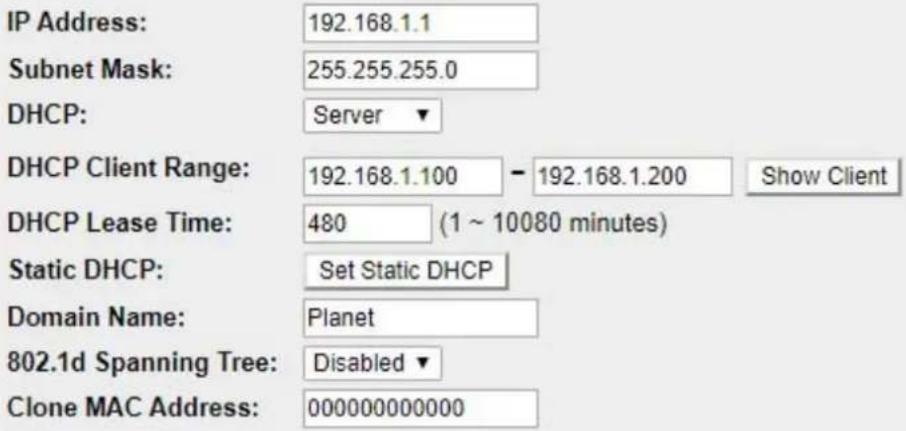
Figure 4-27: LAN Setup
| Object Description | |
| IP Address | The LAN IP address of the Industrial wall-mount Gigabit router and default is 192.168.1.1. You can change it according to your request. |
| Subnet Mask | Default is 255.255.255.0. You can change it according to your request. |
| DHCP | You can select one of them -- Disable, Client, or Server. Default is Server, where the industrial wall-mount Gigabit router can assign IP addresses to the computers automatically. |
| DHCP Client Range | For the Server mode, you must enter the DHCP client IP address range in the field. And you can click the “Show Client” button to show the Active DHCP Client Table. |
| Domain Name | Default is Planet. |
| 802.1d Spanning Tree | You can enable or disable the spanning tree function. |
| Clone MAC Address | You can input an MAC address here for using clone function. |

Note
If you change the device's LAN IP address, you must enter the new one in your browser to get back to the web-based configuration utility. And LAN PCs' gateway must be set to this new IP for successful Internet connection.
4.3.3 VLAN
VLAN (Virtual Local Area Network) allows a physical network to be partitioned into multiple logical networks. Devices on a logical network belong to one group. A device can belong to more than one group. With VLAN, a device cannot directly talk to or hear from devices that are not in the same group. Please refer to the following sections for the details as shown in Figure 4-28.
802.1Q VLAN
Entries in below table are used to config vlan settings. VLANs are created to provide the segmentation services traditionally provided by routers. VLANs address issues such as scalability, security, and network management.
Enable 802.1Q VLAN VLAN ID(1-4095): 1
Forwarding Rule: NAT ▼ Hardware NAT: □
| Port | Member | Tagged |
| port1 | ||
| port2 | ||
| port3 | ||
| port4 | ||
| port5 (WAN) |
Save Save & Apply Reset
Current VLAN Table: VLAN ID Forwarding Rule Tagged Ports Untagged Ports Select Delete Selected Delete All Reset
Change PVID Setting
Figure 4-28: VLAN Setup
| Object Description | |
| Enable 802.1Q VLAN | Check this box to enable 802.1Q VLAN function. |
| VLAN ID | Set VLAN ID (1-4095) |
| Forwarding Rule | Select Bridge or NAT mode |
| Hardware NAT | Check this box to enable Hardware NAT function. |
| Member | Add VLAN without tag to packet |
| Tagged | Add VLAN tag to packet |
| Change PVID setting | Check this box to enable change PVID (default vlan id) |
4.3.4 Route
There are two route types -- Dynamic Route and Static Route. Please refer to the following sections for the details as shown in Figure 4-29.
Routing Setup
This page is used to setup static route protocol.
Enable Dynamic Route
NAT:
RIP Send:
RIP Recv:
RIPng:
Apply Changes
Enabled
Disabled
Disabled
Disabled
Disabled
RIP 1 RIP 2
RIP 1 RIP 2
Enabled
Enable Static Route
IP Address:
Subnet Mask:
Gateway:
Metric:
Interface:
Save
Save & Apply
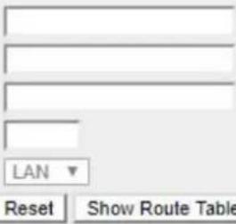
Static Route Table:
| Destination IP Address | Netmask | Gateway | Metric | Interface | Select |
Figure 4-29: Routing setup
■ Dynamic routing
Dynamic routing is a networking technique that provides optimal data routing. Unlike static routing, dynamic routing enables routers to select paths according to real-time logical network layout changes. RIPng exchanges routing information used to compute routes and is intended for IP version 6 (IPv6)-based networks while RIPv1 and RIPv2 is intended for IP version 4 (IPv4)-based networks.
| Object Description | |
| Enable Dynamic Route | Click this box to enable Dynamic Route. |
| NAT | Enable or Disable NAT function |
| RIP Send | Disable:do not send any RIP packet outRIP1: Send RIP1 packet outRIP2. Send RIP2 packet out |
| RIP Recv | Disable : do not receive any RIP packet |
| RIP1: Only receive RIP1 packet | |
| RIP2: Only receive RIP2 packet | |
| RIPng | Enable or Disable RIPng function |
■ Static routing
Static routing is a special type of routing that can be applied in a network to reduce the problem of routing selection and data flow overload caused by routing selection so as to improve the packets forwarding speed. You can set the destination IP address, subnet mask, and gateway to specify a routing rule. The destination IP address and subnet mask determine a destination network or host to which the router sends packets through the gateway.
| Object Description | |
| Enable Static Route | Click this box to enable Static Route. |
| IP Address | The network or host IP address desired to access. |
| Subnet Mask | The subnet mask of destination IP. |
| Gateway | The gateway is the router or host's IP address to which packet was sent. It must be the same network segment with the WAN or LAN port. |
| Metric | The route metric is a value from 1 to 16 that indicates the cost of using this route. |
| Interface | Select the interface that the IP packet must use to transmit out of the router when this route is used. |
| Show Routing Table | Press the button to show all the routing tables of the system. |
| Static Routing table | It only shows the static routing table and you can delete one or all. |
4.3.5 DDNS
The industrial wall-mount Gigabit router offers the DDNS (Dynamic Domain Name System) feature, which allows the hosting of a website, FTP server, or e-mail server with a fixed domain name (named by yourself) and a dynamic IP address, and then your friends can connect to your server by entering your domain name no matter what your IP address is. Before using this feature, you need to sign up for DDNS service providers such as PLANET DDNS or www.dyndns.org. The Dynamic DNS client service provider will give you a password or key.
Planet DDNS
PLANET DDNS website provides a free DDNS (Dynamic Domain Name Server) service for PLANET devices. Whether the IP address used on your PLANET device supporting DDNS service is fixed or dynamic, you can easily connect the devices anywhere on the Internet with a meaningful or easy-to-remember name you gave. PLANET DDNS provides two types of DDNS services -- Dynamic DDNS and Easy DDNS -- as shown in Figure 4-30.
PLANET Dynamic DDNS
For example, you've just installed a PLANET IP camera with dynamic IP like 210.66.155.93 in the network. You can name this device as "Mycam1" and get the URL link as Mycam1.planetddns.com. Thus, you don't need to memorize the exact IP address but just the URL link: Mycam1.planetddns.com.
PLANET Easy DDNS
PLANET Easy DDNS is an easy way to help user to get your Domain Name with just one click. You can just log in to the Web Management Interface of your devices, say, your IP Camera, check the DDNS menu and just enable it. Once you enabled the Easy DDNS, your PLANET Network Device will use the format PLxxxxxx where xxxxxx is the last 6 characters of your MAC address that can be found on the Web page or bottom label of the device. (For example, A8-F7-E0-81-96-C9 will be converted into pt8196c9.planetddns.com)
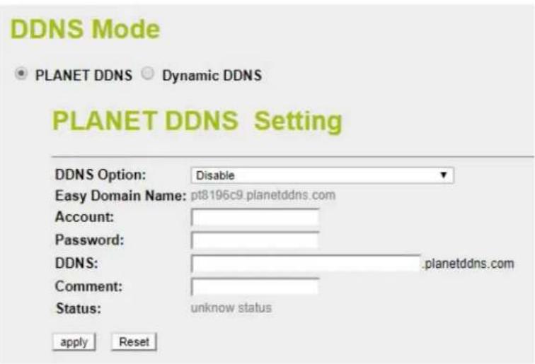
Figure 4-30: PLANET DDNS
| Object Description | |
| DDNS Option | Disable: do not activate PLANET DDNS functionEnable Easy DDNS: activate Easy DDNS serviceEnable Dynamic DDNS: activate Easy Dynamic DDNS service |
| Account | The User Name for PLANET DDNS account. |
| Password | The Password for PLANET DDNS account. |
| DDNS | The DDNS name of PLANET device |
| Comment | Add some comment for this item. |
| Status | Connection staus for PLANET DDNS |
■ Dynamic DNS
The industrial wall-mount Gigabit router supports DynDNS and TZO DDNS service providers for Dynamic DNS as shown in Figure 4-31.
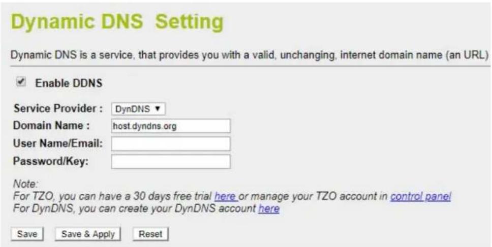
Figure 4-31: Dynamic DNS
| Object Description | |
| Enable DDNS | Check the box to enable the Dynamic DNS function. |
| Service Provider | Select the DDNS service provider from the drop-down menu, such as DynDNS or TZO. |
| Domain Name | Enter the domain name you have registered from the DDNS service provider. |
| User Name/Email | Enter the user name or email you have registered from the DDNS service provider. |
| Password/Key | Enter the password you have registered from the DDNS service provider. |
4.3.6 IPv6 WAN Setting
This page is used to configure parameter for IPv6 internet network which connects to WAN port of your industrial wall-mount Gigabit router as shown in Figure 4-32. It allows you to enable IPv6 function and set up the parameters of the router's WAN. In this setting, you may change WAN original type and WAN link type.
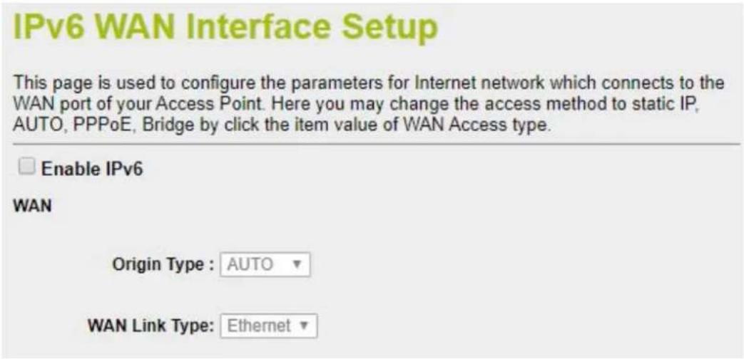
Figure 4-32: IPv6 WAN setup
| Object Description | |
| Enable IPv6 | Click this box to enable IPv6 configuration. |
| Original Type | Select either Auto or Static. In Auto you could choose the DHCP type for Stateless Address Auto or Stateful Address Auto Configuration. In Static you need to fill in the Static IP address table. |
| WAN Link Type | Select IPv6 WAN type either by using Ethernet or PPPoE. |
4.3.7 IPv6 LAN Setting
IPv6 LAN Setting will be only available if you enable IPv6 WAN. Make sure IPv6 WAN is enabled before you could configure the IPv6 LAN. The setup is shown in Figure 4-33.
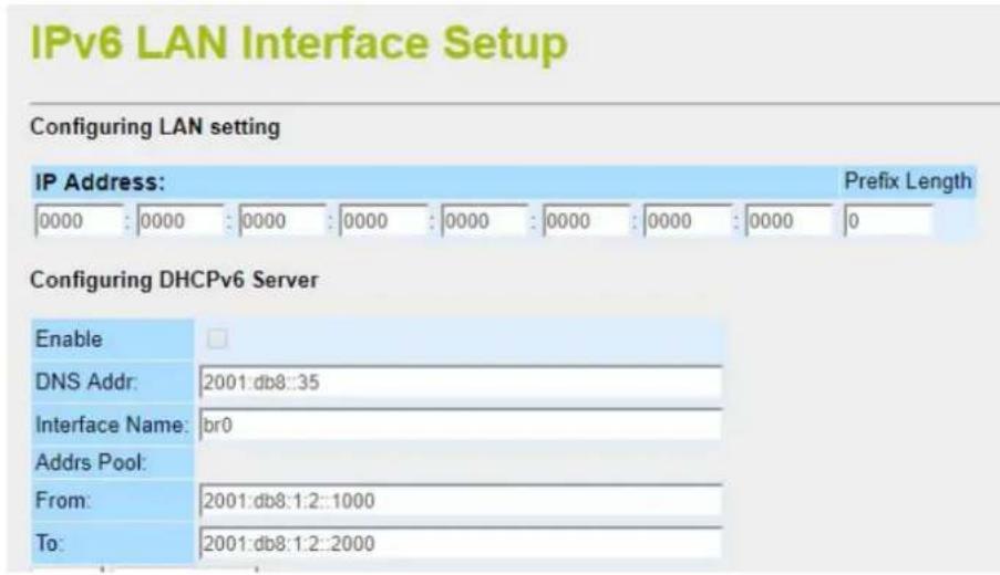
Figure 4-33: IPv6 LAN Setup
| Object Description | |
| Enable IPv6 LAN | Click this box to enable IPv6 LAN configuration. |
| DNS Address | Enter IPv6 DNS Address assigned by your ISP. |
| Interface Name | Enter assigned Interface name of the IPv6 LAN port. |
| From | Enter assigned starting Address pool. |
| To | Enter assigned ending Address pool. |
4.3.8 RADVD
The RADVD configuration is responsible for defining interface setting, prefixes, routers and RDNSS announcements. The setup is shown in Figures 4-34 to 4-35.
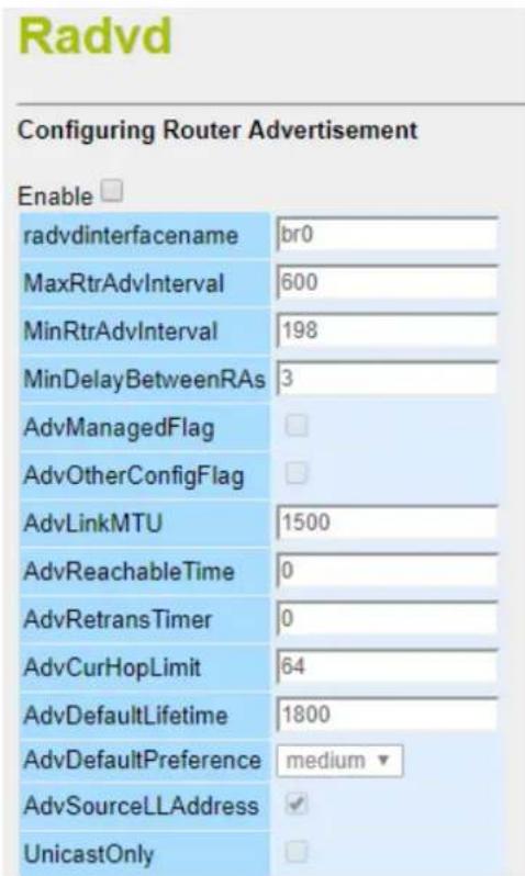
Figure 4-34: IPv6 RADVD
| Object Description | |
| Enable | Click this box to enable RADVD configuration. |
| Radvdinterfacename | Assigned interface name of RADVD. |
| MaxRtrAdvInterval | Enter the maximum time allowed between sending unsolicited multicast router advertisements from the interface in seconds. By default the value is 600. |
| MinRtrAdvInterval | Enter the minimum time allowed between sending unsolicited multicast router advertisements from the interface in seconds. By default the value is 198. |
| MinDelayBetweenRAs | Enter the minimum time allowed between sending multicast router advertisements from the interface in seconds By default the value is 3 |
| AdvManagedFlag | To enables and disable the additional stateful administered auto-configuration protocol. |
| AdvOtherConfigFlag | To enable and disable the auto-configuration of additional, non address information. |
| AdvLinkMTU | Enter value of Advertises the given link MTU in the RA if specified. 0 value disables MTU advertisements. |
| AdvReachable Time | Enter value of Advertises assumed reach-ability time in milliseconds of neighbors in the RA if specified. 0 value disables reach-ability advertisements. |
| AdvRetransTime | Enter value of Advertises wait time in milliseconds between Neighbor Solicitation messages in the RA if specified. 0 value is disables re-transmit advertisements |
| AdvCurHopLimit | Enter value of Advertises the default Hop Count value for outgoing unicast packets in the RA. 0 value is disables hopcount advertisements. By default value is set to 64. |
| AdvDefaultLifetime | Enter value of Advertises the lifetime of the default router in seconds. 0 value is indicates that the node is no default router. By default it is set to 1800. |
| AdvDefaultPreference | Select the advertises default router preference. By default it is set to medium. |
| AdvSourceLLAddress | To include the link-layer address of the outgoing interface in the RA. |
| UnicastOnly | To enable the indication that the underlying link is not broadcast capable, prevents unsolicited advertisements from being sent. |
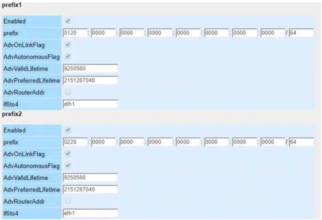
Figure 4-35: IPv6 RADVD Prefix
| Object Description | |
| Enable RADVD prefix | Click this box to enable RADVD prefix. |
| Prefix | Assigned the advertised IPv6 route prefix. |
| AdvOnLinkFlag | To enable indication that this prefix can be used for on-link determination. |
| AdvAutonomousFlag | To enable indication that this prefix can be used for autonomous address configuration. |
| AdvValidLifetime | Enter the advertising length of time in seconds that the prefix is valid for purpose of on-link determination. |
| AdvPreferredLifeTime | Enter the advertising length of time in seconds that addresses generated from the prefix via stateless address autoconfiguration remain preferred.The special value infinity means forever |
| AdvRouterAddr | Enable indication of the address of interface that is sent instead of network prefix. |
| if6to4 | Specifies a logical interface name to derive a 6to4 prefix origin. |
4.3.9 Tunnel (6 over 4)
6 to 4 is an IPv6 address assignment and automatic tunneling technology that is used to provide unicast IPv6 connectivity between IPv6 sites and hosts across the IPv4 Internet. The setup is shown in Figure 4-36.
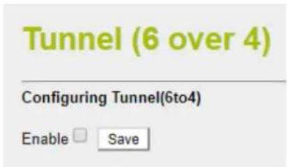
Figure 4-36: IPv6 Tunnel (6 over 4)
| Object Description | |
| Enable Tunnel (6 to 4) | Click this box to enable Tunnel (6 to 4). |
4.4 Security
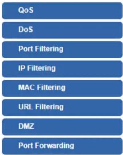
The Security menu provides QoS, firewall and access filtering as shown in Figure 4-37. Please refer to the following sections for the details.
flowchart
graph TD
    A["QoS"] --> B["DoS"]
    B --> C["Port Filtering"]
    C --> D["IP Filtering"]
    D --> E["MAC Filtering"]
    E --> F["URL Filtering"]
    F --> G["DMZ"]
    G --> H["Port Forwarding"]
Figure 4-37: Security menu
| Object Description | |
| QoS | Allows to set QoS (Quality of Service). |
| DoS | Allows to set DoS (Denial of Service). |
| Port Filtering | Allows to set Port Filtering. |
| IP Filtering | Allows to set IP Filtering. |
| MAC Filtering | Allows to set MAC Filtering |
| URL Filtering | Allow to set MAC Filtering. |
| DMZ | Allow to set DMZ. |
| Port Forwarding | Allow to set Port Forwarding |
4.4.1 QoS
The QoS (Quality of Service) helps improve your network gaming performance by prioritizing applications as shown in Figure 4-38. By default the bandwidth control is disabled and application priority is not classified automatically. In order to complete this settings, please follow the steps below.
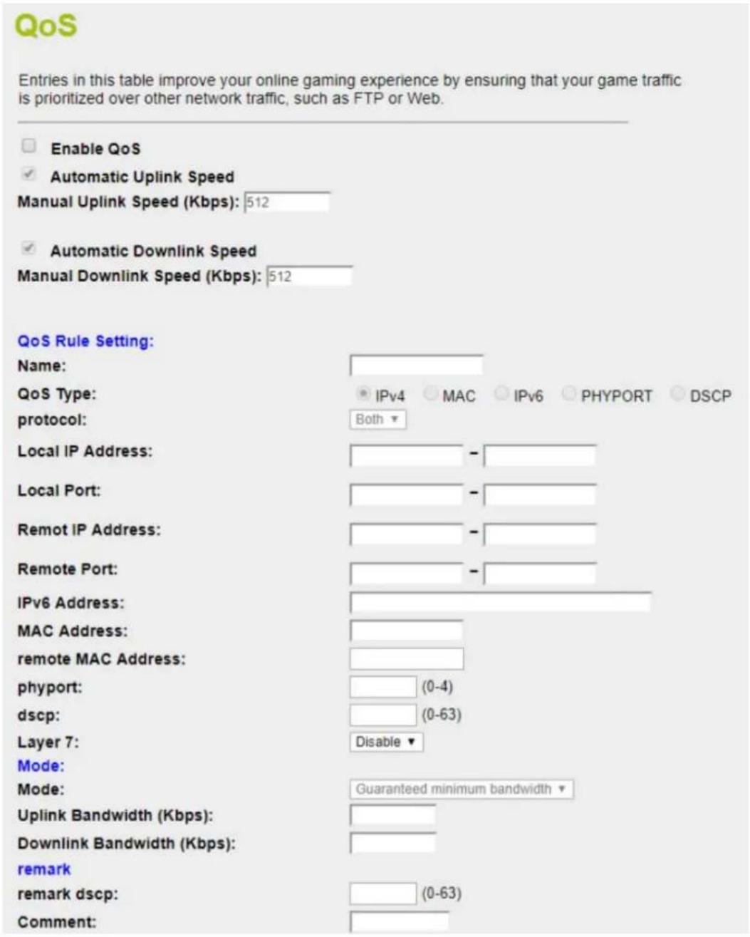
Figure 4-38: QoS
| Object Description | |
| Enable QoS | Check the box to enable the QoS function. |
| Automatic Uplink Speed | Check the box to adjust the uplink speed automatically by the Industrial wall-mount Gigabit router. Or enter the uplink data rate manually in the field below. |
| Automatic Downlink Speed | Check the box to adjust the downlink speed automatically by the Industrial wall-mount Gigabit router. Or enter the downlink data rate manually in the field below. |
| Name | Add a QoS rule name. |
| QoS Type | Choose type of QoS either by IPv4, MAC Address, IPv6, PHYPORT or DSCP. |
| Protocol | Select type of protocol to use for QoS. It can be either TCP, UDP or both. |
| Select IP | Select connected client IP Address. |
| Local IP Address | Enter local IP Address range of client or device (if QoS type is IPv4). |
| Local Port | Enter local port range of client or device (if QoS type is IPv4). |
| Remote IP Address | Enter remote IP Address range of client or device (if QoS type is IPv4). |
| Remote Port | Enter remote port range of client or device (if QoS type is IPv4). |
| IPv6 Address | Enter IPv6 Address of client or device (if QoS type is IPv6). |
| MAC Address | Enter MAC Address of client or device (if QoS type is MAC). |
| PHYPORT | Enter Physical Ethernet port of connected client or device (if QoS type is PHYPORT). |
| DSCP | Enter DSCP number of client or device (if QoS type is DSCP). |
| Mode | Select QoS mode for “Guaranteed minimum bandwidth” or “Restricted maximum bandwidth”. |
| Uplink Bandwidth | Enter value of upload limitation value according to the QoS mode. |
| Downlink Bandwidth | Enter value of download limitation value according to the QoS mode. |
| remark dscp | Insert a remark on DSCP configuration. |
| Comment | Insert comment of the DSCP configuration as references. |
4.4.2 DoS
A "Denial-of-Service" (DoS) attack is characterized by an explicit attempt by hackers to prevent legitimate users of a service from using that service. The industrial wall-mount Gigabit router can prevent specific DoS attacks as shown in Figure 4-39.
Denial of Service
A "denial-of-service" (DoS) attack is characterized by an explicit attempt by hackers
Enable DoS Prevention
Whole System Flood: SYN
Whole System Flood: FIN
Whole System Flood: UDP
Whole System Flood: ICMP
Per-Source IP Flood: SYN
Per-Source IP Flood: FIN
Per-Source IP Flood: UDP
Per-Source IP Flood: ICMP
TCP/UDP PortScan
ICMP Smurf
IP Land
IP Spoof
IP TearDrop
PingOfDeath
TCP Scan
TCP SynWithData
UDP Bomb
UDP EchoChargen
Select ALL Clear ALL
Enable Source IP Blocking
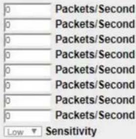

Figure 4-39: DoS
| Object Description | |
| Enable DoS Prevention | Check to enable DoS function.User may set other related configurations about DoS below. |
| Whole System Flood SYN | Check the box to enable. If enabled, when the number of the current SYN packets is beyond the set value, the router will startup the blocking function immediately. |
| Whole System Flood FIN | Check the box to enable. If enabled, when the number of the current FIN packets is beyond the set value, the router will startup the blocking function immediately. |
| Whole System Flood UDP | Check the box to enable. If enabled, when the number of the current UPD-FLOOD packets is beyond the set value, the router will startup the blocking function immediately. |
| Whole System Flood ICMP | Check the box to enable. If enabled, when the number of the current ICMP-FLOOD packets is beyond the set value, the router will startup the blocking function immediately. |
| Per-Source IP Flood SYN | Check the box to enable. When the IP Flood SYN Detection is enabled, the router has the ability to block malicious devices that are attempting to flood devices. |
| Per-Source IP Flood FIN | Check the box to enable. When the IP Flood FIN Detection is enabled, the router has the ability to block malicious devices that are attempting to flood devices. |
| Per-Source IP Flood UDP | Check the box to enable. When the IP Flood UDP Detection is enabled, the router has the ability to block malicious devices that are attempting to flood devices. |
| Per-Source IP Flood ICMP | Check the box to enable. When the IP Flood IGMP Detection is enabled, the router has the ability to block malicious devices that are attempting to flood devices. |
| TCP/UDP PortScan | Check the box will I block against hackers from probe to router system remotely and determine what TCP/UDP port are open. |
| ICMP Smurf | Check box to enable protection against ICMP Smurf attack. |
| IP Land | Check the box to enable the protection against LAND attack. |
| IP Spoof | Check box to enable protection against IP Spoofing attack on device within network. |
| IP TearDrop | Check box to enable protection against Teardrop attack that targeting on TCP/IP fragmentation reassembly codes. |
| PingOfDeath | Check box to enable protection against Ping of Death attack that aims to disrupt a targeted machine by sending a packet larger that maximum allowable size causing the target machine to freeze or crash. |
| TCP Scan | Check the box to enable protection against TCP Scan. TCP Scan is technique use to identify listening TCP Port. |
| TCP SynWithData | Check the box to block TCP Syn With Data evasion technique. |
| UDP Bomb | Check the box to enable protection against UDP Bomb or called as UDP Flood or packet storm. |
| UDP EchoChargen | Check the box to enable protection against CharGEN attack. CharGEN attack is carried out by sending small packets carrying a spoofed IP of the target to the internet enabled devices running CharGEN. |
| Select All | Select to enable all the DoS protection method. |
| Enable Source IP Blocking | Enter value of time duration for IP Blocking. |
4.4.3 Port Filtering
Entries in this table are used to restrict certain types of data packets from your local network to Internet through the Gateway. Use of such filters can be helpful in securing or restricting your local network as shown in Figure 4-40
Port Filtering
Entries in this table are used to restrict certain types of data packets from your local network to Internet through the Gateway. Use of such filters can be helpful in securing or restricting your local network.
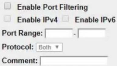
Figure 4-40: Port Filtering
| Object Description | |
| Enable Port Filtering | Check box to enable Port Filtering function. |
| Enable IPv4 | Check box to enable Port filtering method using IPv4. |
| Enable IPv6 | Check box to enable Port filtering method using IPv6. |
| Port Range | Add ports you want to control. |
| Protocol | Select the port number protocol type (TCP, UDP or both). If you are unsure, then leave it to the default both protocols. |
| Comment | Enter the description for this setting. |
4.4.4 IP Filtering
IP Filtering is used to block internet or network access to specific IP addresses on your local network as shown in Figure 4-41. The restricted user may still be able to log in to the network but will not be able to access the internet. To begin blocking access to an IP address, enable IP Filtering and enter the IP address of the user you wish to block.
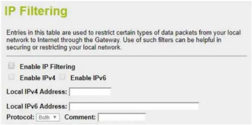
Figure 4-41: IP Filtering
| Object Description | |
| Enable IP Filtering | Check this box to enable IP Filter function |
| Enable IPv4 | Check this box to enable IP filtering method using IPv4. |
| Enable IPv6 | Check this box to enable IP filtering method using IPv6. |
| Local IP Address | Add LAN IP address you want to control |
| Protocol | Select the port number protocol type (TCP, UDP or both).If you are unsure, then leave it to the default both protocol |
| Comment | Enter the description for this setting. |
4.4.5 MAC Filtering
Entries in this table are used to restrict certain types of data packets from your local network to Internet through the Industrial wall-mount Gigabit router. Use of such filters can be helpful in securing or restricting your local network as shown in Figure 4-42.
MAC Filtering
Entries in this table are used to restrict certain types of data packets from your local network to Internet through the Gateway. Use of such filters can be helpful in securing or restricting your local network.
Enable MAC Filtering
MAC Address:
Comment:
Figure 4-42: MAC Filtering
| Object Description | |
| Enable MAC Filtering | Check this box to enable MAC filtering. |
| MAC Address | Add MAC address you want to control. |
| Comment | Enter the description for this setting. |
4.4.6 URL Filtering
URL filter is used to deny LAN users from accessing the internet as shown in Figure 4-43. Block those URLs which contain keywords listed below.
URL Filtering
URL filter is used to deny LAN users from accessing the internet. Block those URLs which contain keywords listed below.
Enable URL Filtering
deny url address(black list)
allow url address(white list)
URL Address:
Figure 4-43: URL Filtering
| Object Description | |
| Enable URL Filtering | Check this box to enable URL Filter function. |
| deny url address (black list) | deny access listed URL in the Current URL Filtering table and allow other URLs which are not in the list. |
| allow url address (white list) | allow access listed URL in the Current URL Filtering table and deny other URLs which are not in the list. |
| URL Address | The URL Address that you want to filter. |
4.4.7 DMZ
A Demilitarized Zone is used to provide Internet services without sacrificing unauthorized access to its local private network as shown in Figure 4-44. Typically, the DMZ host contains devices accessible to Internet traffic, such as Web (HTTP) servers, FTP servers, SMTP (e-mail) servers and DNS servers.
DMZ
A Demilitarized Zone is used to provide Internet services without sacrificing unauthorized access to its local private network. Typically, the DMZ host contains devices accessible to Internet traffic, such as Web (HTTP) servers, FTP servers, SMTP (e-mail) servers and DNS servers.

Enable DMZ
DMZ Host IP Address:
Figure 4-44: DMZ
| Object Description | |
| Enable DMZ | Check the box to enable DMZ function. If the DMZ Host Function is enabled, it means that you set up DMZ host at a particular computer to be exposed to the Internet so that some applications/software, especially Internet / online game can have two way connections. |
| DMZ Host IP Address | Enter the IP address of a particular host in your LAN which will receive all the packets originally going to the WAN port / Public IP address above. |
4.4.8 Port Forwarding
Entries in this table allow you to automatically redirect common network services to a specific machine behind the NAT firewall as shown in Figure 4-45. These settings are only necessary if you wish to host some sort of server like a web server or mail server on the private local network behind your Router's NAT firewall.
Port Forwarding
Entries in this table allow you to automatically redirect common network services to a specific machine behind the NAT firewall. These settings are only necessary if you wish to host some sort of server like a web server or mail server on the private local network behind your Gateway's NAT firewall.
Enable Port Forwarding

Figure 4-45: Port Forwarding
| Object Description | |
| Enable Port Forwarding | Check the box to enable Port Forwarding function |
| Local IP Address | Enter Local IP address of specified host or server on the private local network. |
| Protocol | Select the port number protocol type (TCP, UDP or both). If you are unsure, then leave it to the default both protocols. |
| Local Port Range | Enter local ports you want to control. For TCP and UDP Services, enter the beginning of the range of port numbers used by the service. If the service uses a single port number, enter it in both the start and finish fields. |
| Remote IP Address | Enter remote IP address of external IP Address. You could set to 0.0.0.0 for any IP address. |
| Remote Port Range | Enter remote ports you want to control. For TCP and UDP Services, enter the beginning of the range of port numbers used by the service. If the service uses a single port number, enter it in both the start and finish fields. |
| Comment | Enter the description for this setting. |
4.5 Maintenance
The Maintenance menu provides the following features for managing the system as Figure 4-52 is shown below:
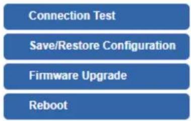
flowchart
graph TD
    A["Connection Test"] --> B["Save/Restore Configuration"]
    B --> C["Firmware Upgrade"]
    C --> D["Reboot"]
Figure 4-52: Maintenance Menu
| Object Description | |
| Connection Test | Allows you to issue ICMP PING packets to troubleshoot IP. |
| Save/Restore Configuration | Backup and restore setting file via USB HDD or PC. |
| Firmware | Firmware upgrade. |
| Reboot | Reboot the system |
4.5.1 Connection Test
The page allows you to issue ICMP PING packets to troubleshoot IP connectivity issues. After you press "Ping", 5 ICMP packets are transmitted, and the sequence number and roundtrip time are displayed upon reception of a reply. The Page refreshes automatically until responses to all packets are received, or until a timeout occurs. The ICMP Ping is shown in Figure 4-53.
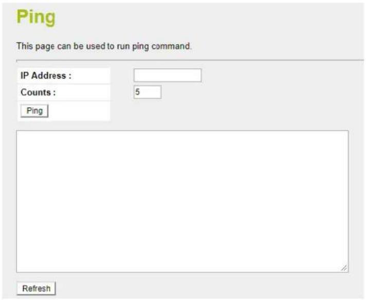
Figure 4-53: Ping
| Object Description | |
| IP Address | The destination IP Address. |
| Counts | The time of ping. |

Be sure the target IP address is within the same network subnet of the industrial wall-mount Gigabit router, or you have to set up the correct gateway IP address.
4.5.2 Save/Restore Configuration
This page shows the status of the configuration. You may save the setting file to the PC as Figure 4-54 is shown below:
Save/Reload Settings
This page allows you save current settings to a file or reload the settings from the file which was saved previously. Besides, you could reset the current configuration to factory default.
Save Settings to File: Save...
Load Settings from File: Choose File No file chosen
Reset Settings to Default: Reset
Upload
Figure 4-54: Save/Restore Configuration
| Object Description | |
| Save Settings to File | Press the Save button to save setting file to PC. |
| Load Settings from File | Press the Choose File button to select the setting file, and then press the Unload the button to upload setting file from PC. |
| Reset Setting to Default | Press the Reset button to reset to factory default. |
4.5.3 Upgrading Firmware
This page provides the firmware upgrade of industrial wall-mount Gigabit router as shown in Figure 4-55.

Figure 4-55: Firmware upgrade
| Object | Description |
| Choose File | Press the button to select the firmware. |
| Upload | Press the button to upgrade firmware to system. |
| Reset | Press this button to cancel the file. |
4.5.4 Reboot
This page enables the device to be rebooted from a remote location. Once the Reboot button is pressed, users have to re-log in the Web interface for about 60 seconds later as Figure 4-56 is shown below:
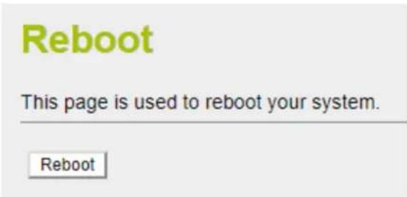
Figure 4-56: Reboot
| Object | Description |
| Reboot | Press the button to reboot system. |

You can also check the SYS LED on the front panel to identify whether the System is loaded completely or not. If the SYS LED is blinking, then it is in the firmware load stage; if the SYS LED light is on, you can use the Web browser to log in the industrial wall-mount Gigabit router.
Appendix A: Troubleshooting
This chapter contains information to help you solve issues. If the industrial wall-mount Gigabit router is not functioning properly, make sure the industrial wall-mount Gigabit router was set up according to instructions in this manual.
■ The Link LED is not lit
Solution:
Check the cable connection and remove duplex mode of the industrial wall-mount Gigabit router
■ Some stations cannot talk to other stations located on the other port
Solution:
Please check the VLAN settings.
■ Performance is bad
Solution:
Check the full duplex status of the industrial wall-mount Gigabit router. If the industrial wall-mount Gigabit router is set to full duplex and the partner is set to half duplex, then the performance will be poor. Please also check the in/out rate of the port.
■ Why the Router doesn't connect to the network
Solution:
-
Check the LNK/ACT LED on the router
-
Try another port on the router
-
Make sure the cable is installed properly
-
Make sure the cable is the right type
-
Turn off the power. After a while, turn on power again
■ 1000BASE-T port link LED is lit, but the traffic is irregular
Solution:
Make sure the attached device is not set to dedicated full duplex. Some devices use a physical or software switch to change duplex modes. Auto-negotiation may not recognize this type of full-duplex setting.
■ Router does not power up
Solution:
-
Terminal block or DC jack is not inserted or faulty
-
Check whether the terminal block or DC jack is inserted correctly
-
If the terminal block or DC jack is inserted correctly; check that the power source is working by connecting a different device in place of the router.
-
If that device works, refer to the next step.
-
If that device does not work, check the power source
Appendix B: Planet Smart Discovery Utility
For easily listing the industrial wall-mount Gigabit router in your Ethernet environment, Planet Smart Discovery Utility from PLANET download center is an ideal solution.
The following installation instructions guide you to running the Planet Smart Discovery Utility.
Step 1: Download the Planet Smart Discovery Utility to the administrator PC.
Step 2: Run this utility and the following screen appears.

Planet_Utility.exe PLANET Corp.
Step 3: Press the "Refresh" button for the currently connected devices in the discovery list as shown in the following screen:
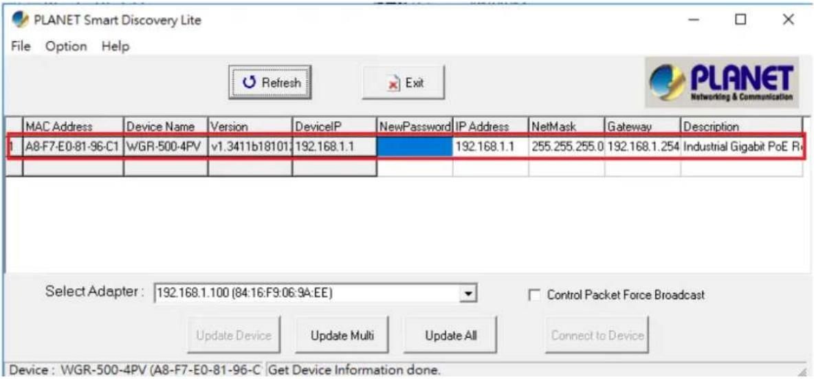
Step 3: Press the "Connect to Device" button and then the Web login screen appears.

The fields in the white background can be modified directly, and then you can apply the new setting by clicking the "Update Device" button.
Appendix C: Planet DDNS
First of all, please go to http://www.planetddns.com to register a Planet DDNS account, and refer to the FAQs (http://www.planetddns.com/index.php/faq) for how to register a free account.
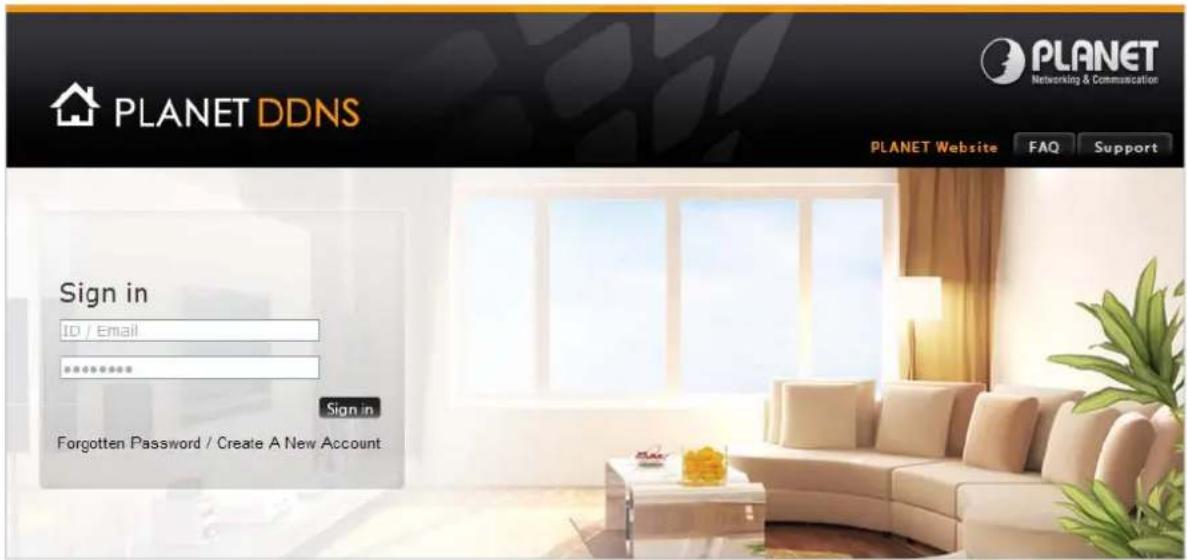
When you finish your DDNS account, please return to WAN Setup -> WAN Setup to set up your WAN type which can be connected to external network.
WAN Interface Setup
This page is used to configure the parameters for Internet network which PPPoE, PPTP or L2TP by click the item value of WAN Access type.
WAN Access Type:
Host Name:
MTU Size:
DHCP Client ▼
Static IP
DHCP Client
PPPoE
PPTP
L2TP
Attain DNS Automatically
Set DNS Manually
DNS 1:
DNS 2:
DNS 3:
8.8.8.6
(No text)
1
Step 1. Enable PLANET Dynamic DDNS, and enter account, password, and DDNS.
PLANET DDNS Setting
DDNS Option:
Enable Dynamic DDNS

Easy Domain Name:
pt8196c9.planetddns.com
Account:
username
Password:
[Unreadable]
DDNS:
ddnsdemo
.planetddns.com
Comment:
The Ground Truth image displays a single, solid horizontal line. According to Rule 2 (UNDERSCORE & LINE RULES), this is a stylistic or background line, not a placeholder underscore. Therefore, the OCR result must ignore it and output nothing or only meaningful text. The provided OCR content is "____", which consists of four underscores. This is an incorrect interpretation of the line as a placeholder, violating the rule that stylistic lines must be ignored. The OCR has hallucinated placeholder underscores where none should exist in the GT. Hence, the OCR result is inconsistent with the Ground Truth.
Step 2. Go to Network-> WAN setup page to allow remote access from WAN port.
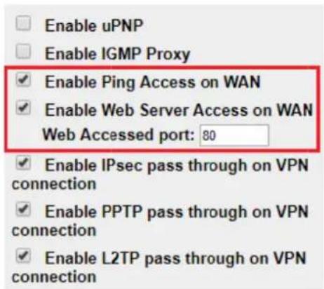
Step 3. Apply the settings, and ensure you have connected the WAN port to the internet by Ethernet cable.
Step 4. In a remote computer, enter the Domain Name to the internet browser's address bar.

Lastly you can go to My Devices page of PlanetDDNS website to check if the "Last Connection IP" is displayed. This indicates your DDNS service is working properly.
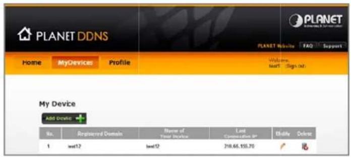
Appendix D: Glossary
A
ARP
ARP is an acronym for Address Resolution Protocol. It is a protocol that used to convert an IP address into a physical address, such as an Ethernet address. ARP allows a host to communicate with other hosts when only the Internet address of its neighbors is known. Before using IP, the host sends a broadcast ARP request containing the Internet address of the desired destination system.
ARP Inspection
ARP Inspection is a secure feature. Several types of attacks can be launched against a host or devices connected to Layer 2 networks by "poisoning" the ARP caches. This feature is used to block such attacks. Only valid ARP requests and responses can go through the switch device.
Auto-Negotiation
Auto-negotiation is the process where two different devices establish the mode of operation and the speed settings that can be shared by those devices for a link.
D
Default Gateway (Router)
Every non-router IP device needs to configure a default gateway's IP address. When the device sends out an IP packet, if the destination is not on the same network, the device has to send the packet to its default gateway, which will then send it out towards the destination.
DHCP
DHCP is an acronym for Dynamic Host Configuration Protocol. It is a protocol used for assigning dynamic IP addresses to devices on a network.
DHCP used by networked computers (clients) to obtain IP addresses and other parameters such as the default gateway, subnet mask, and IP addresses of DNS servers from a DHCP server.
The DHCP server ensures that all IP addresses are unique, for example, no IP address is assigned to a second client while the first client's assignment is valid (its lease has not expired). Therefore, IP address pool management is done by the server and not by a human network administrator.
Dynamic addressing simplifies network administration because the software keeps track of IP addresses rather than requiring an administrator to manage the task. This means that a new computer can be added to a network without the hassle of manually assigning it a unique IP address.
DHCP Relay
DHCP Relay is used to forward and to transfer DHCP messages between the clients and the server when they are not on the same subnet domain.
The DHCP option 82 enables a DHCP relay agent to insert specific information into a DHCP request packets when forwarding client DHCP packets to a DHCP server and remove the specific information from a DHCP reply packets when forwarding server DHCP packets to a DHCP client. The DHCP server can use this information to implement IP address or other assignment policies. Specifically the option works by setting two sub-options: Circuit ID (option 1) and Remote ID (option2). The Circuit ID sub-option is supposed to include information specific to which circuit the request came in on. The Remote ID sub-option was designed to carry information relating to the remote host end of the circuit. The definition of Circuit ID in the switch is 4 bytes in length and the format is "vlan_id" "module_id" "port_no". The parameter of "vlan_id" is the first two bytes represent the VLAN ID. The parameter of "module_id" is the third byte for the module ID (in standalone switch it always equal 0, in stackable switch it means switch ID). The parameter of "port_no" is the fourth byte and it means the port number. The Remote ID is 6 bytes in length, and the value is equal the DHCP relay agents MAC address.
DNS
DNS is an acronym for Domain Name System. It stores and associates many types of information with domain names. Most importantly, DNS translates human-friendly domain names and computer hostnames into computer-friendly IP addresses. For example, the domain name www.example.com might translate to 192.168.0.1.
DoS
DoS is an acronym for Denial of Service. In a denial-of-service (DoS) attack, an attacker attempts to prevent legitimate users from accessing information or services. By targeting at network sites or network connection, an attacker may be able to prevent network users from accessing email, web sites, online accounts (banking, etc.), or other services that rely on the affected computer.
E
Ethernet Type
Ethernet Type, or EtherType, is a field in the Ethernet MAC header, defined by the Ethernet networking standard. It is used to indicate which protocol is being transported in an Ethernet frame.
F
FTP
FTP is an acronym for File Transfer Protocol. It is a transfer protocol that uses the Transmission Control Protocol (TCP) and provides file writing and reading. It also provides directory service and security features.
H
HTTP
HTTP is an acronym for Hypertext Transfer Protocol. It is a protocol that used to transfer or convey information on the World Wide Web (WWW).
HTTP defines how messages are formatted and transmitted, and what actions Web servers and browsers should take in response to various commands. For example, when you enter a URL in your browser, this actually sends an HTTP command to the Web server directing it to fetch and transmit the requested Web Page. The other main standard that controls how the World Wide Web works is HTML, which covers how Web Pages are formatted and displayed.
Any Web server machine contains, in addition to the Web Page files it can serve, an HTTP daemon, a program that is designed to wait for HTTP requests and handle them when they arrive. The Web browser is an HTTP client, sending requests to server machines. An HTTP client initiates a request by establishing a Transmission Control Protocol (TCP) connection to a particular port on a remote host (port 80 by default). An HTTP server listening on that port waits for the client to send a request message.
HTTPS
HTTPS is an acronym for Hypertext Transfer Protocol over Secure Socket Layer. It is used to indicate a secure HTTP connection.
HTTPS provide authentication and encrypted communication and is widely used on the World Wide Web for security-sensitive communication such as payment transactions and corporate logons.
HTTPS is really just the use of Netscape's Secure Socket Layer (SSL) as a sublayer under its regular HTTP application layering. (HTTPS uses port 443 instead of HTTP port 80 in its interactions with the lower layer, TCP/IP.) SSL uses a 40-bit key size for the RC4 stream encryption algorithm, which is considered an adequate degree of encryption for commercial exchange.
|
ICMP
ICMP is an acronym for Internet Control Message Protocol. It is a protocol that generated the error response, diagnostic or routing purposes. ICMP messages generally contain information about routing difficulties or simple exchanges such as time-stamp or echo transactions. For example, the PING command uses ICMP to test an Internet connection.
IGMP
IGMP is an acronym for Internet Group Management Protocol. It is a communications protocol used to manage the membership of Internet Protocol multicast groups. IGMP is used by IP hosts and adjacent multicast routers to establish multicast group memberships. It is an integral part of the IP multicast specification, like ICMP for unicast connections. IGMP can be used for online video and gaming, and allows more efficient use of resources when supporting these uses.
IP
IP is an acronym for Internet Protocol. It is a protocol used for communicating data across a internet network.
IP is a "best effort" system, which means that no packet of information sent over it is assured to reach its destination in the same condition it was sent. Each device connected to a Local Area Network (LAN) or Wide Area Network (WAN) is given an Internet Protocol address, and this IP address is used to identify
the device uniquely among all other devices connected to the extended network.
The current version of the Internet protocol is IPv4, which has 32-bits Internet Protocol addresses allowing for in excess of four billion unique addresses. This number is reduced drastically by the practice of webmasters taking addresses in large blocks, the bulk of which remain unused. There is a rather substantial movement to adopt a new version of the Internet Protocol, IPv6, which would have 128-bits Internet Protocol addresses. This number can be represented roughly by a three with thirty-nine zeroes after it. However, IPv4 is still the protocol of choice for most of the Internet.
IP Source Guard
IP Source Guard is a secure feature used to restrict IP traffic on DHCP snooping untrusted ports by filtering traffic based on the DHCP Snooping Table or manually configured IP Source Bindings. It helps prevent IP spoofing attacks when a host tries to spoof and use the IP address of another host.
L
LAN
Local Area Network. A LAN is a group of computers and devices connected together in a relatively small area (such as a house or an office). Your network is considered a LAN.
N
NAT
Network Address Translation. NAT technology translates IP addresses of a local area network to a different IP address for the Internet Using the NAT capability of WGR-500 Series, you can access the Internet from any computer on your network without having to purchase more IP addresses from your ISP.
NetBIOS
NetBIOS is an acronym for Network Basic Input/Output System. It is a program that allows applications on separate computers to communicate within a Local Area Network (LAN), and it is not supported on a Wide Area Network (WAN).
The NetBIOS giving each computer in the network both a NetBIOS name and an IP address corresponding to a different host name, provides the session and transport services described in the Open Systems Interconnection (OSI) model.
NTP
NTP is an acronym for Network Time Protocol, a network protocol for synchronizing the clocks of computer systems. NTP uses UDP (datagrams) as transport layer.
PD
PD is an acronym for Powered Device. In a PoE> system the power is delivered from a PSE (power sourcing equipment) to a remote device. The remote device is called a PD.
PHY
PHY is an abbreviation for Physical Interface Transceiver and is the device that implement the Ethernet physical layer (IEEE-802.3).
PING
ping is a program that sends a series of packets over a network or the Internet to a specific computer in order to generate a response from that computer. The other computer responds with an acknowledgment that it received the packets. Ping was created to verify whether a specific computer on a network or the Internet exists and is connected.
ping uses Internet Control Message Protocol (ICMP) packets. The PING Request is the packet from the origin computer, and the PING Reply is the packet response from the target.
POP3
POP3 is an acronym for Post Office Protocol version 3. It is a protocol for email clients to retrieve email messages from a mail server.
POP3 is designed to delete mail on the server as soon as the user has downloaded it. However, some implementations allow users or an administrator to specify that mail be saved for some period of time.
POP can be thought of as a "store-and-forward" service.
An alternative protocol is Internet Message Access Protocol (IMAP). IMAP provides the user with more capabilities for retaining e-mail on the server and for organizing it in folders on the server. IMAP can be thought of as a remote file server.
POP and IMAP deal with the receiving of e-mail and are not to be confused with the Simple Mail Transfer Protocol (SMTP). You send e-mail with SMTP, and a mail handler receives it on your recipient's behalf.
Then the mail is read using POP or IMAP. IMAP4 and POP3 are the two most prevalent Internet standard protocols for e-mail retrieval. Virtually all modern e-mail clients and servers support both.
PPPoE
PPPoE is an acronym for Point-to-Point Protocol over Ethernet.
It is a network protocol for encapsulating Point-to-Point Protocol (PPP) frames inside Ethernet frames. It is used mainly with ADSL services where individual users connect to the ADSL transceiver (modem) over Ethernet and in plain Metro Ethernet networks (Wikipedia).
Q
QoS
QoS is an acronym for Quality of Service. It is a method to guarantee a bandwidth relationship between individual applications or protocols.
A communications network transports a multitude of applications and data, including high-quality video and delay-sensitive data such as real-time voice. Networks must provide secure, predictable,
measurable, and sometimes guaranteed services.
Achieving the required QoS becomes the secret to a successful end-to-end business solution. Therefore,
QoS is the set of techniques to manage network resources.
QoS class
Every incoming frame is classified to a QoS class, which is used throughout the device for providing queuing, scheduling and congestion control guarantees to the frame according to what was configured for that specific QoS class. There is a one to one mapping between QoS class, queue and priority. A QoS class of 0 (zero) has the lowest priority.
R
RADIUS
RADIUS is an acronym for Remote Authentication Dial In User Service. It is a networking protocol that provides centralized access, authorization and accounting management for people or computers to connect and use a network service.
S
SHA
SHA is an acronym for Secure Hash Algorithm. It designed by the National Security Agency (NSA) and published by the NIST as a U.S. Federal Information Processing Standard. Hash algorithms compute a fixed-length digital representation (known as a message digest) of an input data sequence (the message) of any length.
SMTP
SMTP is an acronym for Simple Mail Transfer Protocol. It is a text-based protocol that uses the Transmission Control Protocol (TCP) and provides a mail service modeled on the FTP file transfer service. SMTP transfers mail messages between systems and notifications regarding incoming mail.
SNMP
SNMP is an acronym for Simple Network Management Protocol. It is part of the Transmission Control Protocol/Internet Protocol (TCP/IP) protocol for network management. SNMP allow diverse network objects to participate in a network management architecture. It enables network management systems to learn network problems by receiving traps or change notices from network devices implementing SNMP.
T
Tag Priority
Tag Priority is a 3-bit field storing the priority level for the 802.1Q frame.
TCP
TCP is an acronym for Transmission Control Protocol. It is a communications protocol that uses the
Internet Protocol (IP) to exchange the messages between computers.
The TCP protocol guarantees reliable and in-order delivery of data from sender to receiver and distinguishes data for multiple connections by concurrent applications (for example, Web server and e-mail server) running on the same host.
The applications on networked hosts can use TCP to create connections to one another. It is known as a connection-oriented protocol, which means that a connection is established and maintained until such time as the message or messages to be exchanged by the application programs at each end have been exchanged. TCP is responsible for ensuring that a message is divided into the packets that IP manages and for reassembling the packets back into the complete message at the other end.
Common network applications that use TCP include the World Wide Web (WWW), e-mail, and File Transfer Protocol (FTP).
TELNET
TELNET is an acronym for TELetype NETwork. It is a terminal emulation protocol that uses the Transmission Control Protocol (TCP) and provides a virtual connection between TELNET server and TELNET client.
TELNET enables the client to control the server and communicate with other servers on the network. To start a Telnet session, the client user must log in to a server by entering a valid username and password. Then, the client user can enter commands through the Telnet program just as if they were entering commands directly on the server console.
U
UDP
UDP is an acronym for User Datagram Protocol. It is a communications protocol that uses the Internet Protocol (IP) to exchange the messages between computers.
UDP is an alternative to the Transmission Control Protocol (TCP) that uses the Internet Protocol (IP). Unlike TCP, UDP does not provide the service of dividing a message into packet datagrams, and UDP doesn't provide reassembling and sequencing of the packets. This means that the application program that uses UDP must be able to make sure that the entire message has arrived and is in the right order. Network applications that want to save processing time because they have very small data units to exchange may prefer UDP to TCP.
UDP provides two services not provided by the IP layer. It provides port numbers to help distinguish different user requests and, optionally, a checksum capability to verify that the data arrived intact. Common network applications that use UDP include the Domain Name System (DNS), streaming media applications such as IPTV, Voice over IP (VoIP), and Trivial File Transfer Protocol (TFTP).
UPnP
UPnP is an acronym for Universal Plug and Play. The goals of UPnP are to allow devices to connect seamlessly and to simplify the implementation of networks in the home (data sharing, communications, and entertainment) and in corporate environments for simplified installation of computer components
User Priority
User Priority is a 3-bit field storing the priority level for the 802.1Q frame.
V
VLAN
Virtual LAN. A method to restrict communication between switch ports. VLANs can be used for the following applications:
VLAN unaware switching: This is the default configuration. All ports are VLAN unaware with Port VLAN ID 1 and members of VLAN 1. This means that MAC addresses are learned in VLAN 1, and the switch does not remove or insert VLAN tags.
VLAN aware switching: This is based on the IEEE 802.1Q standard. All ports are VLAN aware. Ports connected to VLAN aware switches are members of multiple VLANs and transmit tagged frames. Other ports are members of one VLAN, set up with this Port VLAN ID, and transmit untagged frames.
Provider switching: This is also known as Q-in-Q switching. Ports connected to subscribers are VLAN unaware, members of one VLAN, and set up with this unique Port VLAN ID. Ports connected to the service provider are VLAN aware, members of multiple VLANs, and set up to tag all frames. Untagged frames received on a subscriber port are forwarded to the provider port with a single VLAN tag. Tagged frames received on a subscriber port are forwarded to the provider port with a double VLAN tag.
VLAN ID
VLAN ID is a 12-bit field specifying the VLAN to which the frame belongs.
W
WAN
Wide Area Network. A network that connects computers located in geographically separate areas (e.g. different buildings, cities, countries). The Internet is a wide area network.
- Industrial Wall-mount Gigabit Router
- Trademarks
- Disclaimer
- FCC Warning
- CE Mark Warning
- WEEE Warning
- Revision
- TABLE OF CONTENTS
- Chapter 1. Introduction......5
- Chapter 2. Hardware Installation....13
- Chapter 3. Router Management ......25
- Chapter 4. Configuration in Web UI....28
- Security....64
- Maintenance....75
- Chapter 1. Introduction
- Packet Contents
- Product Descript on
- Compact and Cost-effective for Building Industrial IoT Networks
- IPv6 Support for IoT Networking
- Secure Firewall Protection
- VLAN Support for Isolated Traffic and Security
- Innovative Wall-mount Installation
- Dual Power Input for High Availability Network System
- Product Features
- Physical Port
- Industrial Case and Installation
- Layer 2 Features
- Layer 3 IP Routing Features
- Security
- Management
- Product Specifications
- Chapter 2. Hardware Installation
- Product Outlook
- Front and Bottom Panel
- ■ Res et Button
- DIP Switch
- LED Indications
- Wiring the Power Inputs
- ■ Ter minal Block Connector Pinout
- DC Power Jack
- Installing the industrial wall-mount Gigabit router
- Wall-mot Installation
- Magnet Installation
- DIN-rail Installation
- Chapter 3. Router Management
- This chapter covers the following topics:
- Requirements
- Web Management
- Chapter 4. Configuration in Web UI
- Main Web Page
- Web Panel
- Main Menu
- System
- Dashboard
- WAN/LA N Connection Status
- Port Stattus
- Setup Wizard
- Setup Wizard
- Step 1: Operation Mode
- Operation Mode
- Step 3: Time Zone Setting
- Step 4: LAN Interface Setting
- LAN Interface Setup
- Step 5 WAN Interface Setting
- WAN Interface Setup
- Mode 1 - Static IP
- Mode 2 DHCP Client
- Mode 3 PPPoE
- Mode 4 PPTP
- Mode 5 L2TP
- Status
- Stastics
- Statistics
- Operation Mode
- Router:
- Switch:
- Date and Time
- User Configuration
- Password Setup
- SNMP
- Log
- Network
- WAN Setup
- LAN Setup
- VLAN
- 802.1Q VLAN
- Route
- Routing Setup
- Enable Dynamic Route
- Enable Static Route
- ■ Dynamic routing
- ■ Static routing
- DDNS
- Planet DDNS
- PLANET Dynamic DDNS
- PLANET Easy DDNS
- ■ Dynamic DNS
- IPv6 WAN Setting
- IPv6 LAN Setting
- RADVD
- Tunnel (6 over 4)
- Security
- QoS
- DoS
- Denial of Service
- Enable DoS Prevention
- Port Filtering
- Port Filtering
- IP Filtering
- MAC Filtering
- MAC Filtering
- URL Filtering
- URL Filtering
- DMZ
- DMZ
- Port Forwarding
- Port Forwarding
- Maintenance
- Connection Test
- Save/Restore Configuration
- Save/Reload Settings
- Upgrading Firmware
- Reboot
- Appendix A: Troubleshooting
- Solution:
- Appendix B: Planet Smart Discovery Utility
- Step 1: Download the Planet Smart Discovery Utility to the administrator PC.
- Step 2: Run this utility and the following screen appears.
- Step 3: Press the "Refresh" button for the currently connected devices in the discovery list as shown in the following screen:
- Step 3: Press the "Connect to Device" button and then the Web login screen appears.
- Appendix C: Planet DDNS
- PLANET DDNS Setting
- Appendix D: Glossary
- A
- ARP
- ARP Inspection
- Auto-Negotiation
- D
- Default Gateway (Router)
- DHCP
- DHCP Relay
- DNS
- DoS
- E
- Ethernet Type
- F
- FTP
- H
- HTTP
- HTTPS
- |
- ICMP
- IGMP
- IP
- IP Source Guard
- L
- LAN
- N
- NAT
- NetBIOS
- NTP
- PD
- PHY
- PING
- POP3
- PPPoE
- Q
- QoS
- QoS class
- R
- RADIUS
- S
- SHA
- SMTP
- SNMP
- T
- Tag Priority
- TCP
- TELNET
- U
- UDP
- UPnP
- User Priority
- V
- VLAN
- VLAN ID
- W
- WAN
Brand : Planet
Model : WGR-500
Category : Router