
UT725 - Measurement Uni-T - Free user manual and instructions
Find the device manual for free UT725 Uni-T in PDF.


| Product Type | Digital Multimeter |
| Brand | Uni-T |
| Model | UT725 |
| Display Counts | 6000 |
| DC Voltage Range | 600mV to 1000V |
| AC Voltage Range | 6V to 1000V |
| DC Current Range | 600µA to 10A |
| Resistance Range | 600Ω to 60MΩ |
| Capacitance Range | 60nF to 60mF |
| Frequency Range | 60Hz to 60MHz |
| Diode Test | Yes |
| Continuity Test | Yes |
| Safety Rating | CAT II 1000V, CAT III 600V |
| Power Supply | 9V battery (6F22) |
| Dimensions | 180 x 85 x 50 mm |
| Weight | Approx. 350 g (including battery) |
| Operating Temperature | 0°C to 40°C |
| Storage Temperature | -10°C to 50°C |
| Accessories Included | Test leads, battery, user manual |
| Maintenance | Clean with a damp cloth; no solvents |
Frequently Asked Questions - UT725 Uni-T
User questions about UT725 Uni-T
0 question about this device. Answer the ones you know or ask your own.
Ask a new question about this device
Download the instructions for your Measurement in PDF format for free! Find your manual UT725 - Uni-T and take your electronic device back in hand. On this page are published all the documents necessary for the use of your device. UT725 by Uni-T.
USER MANUAL UT725 Uni-T
natural_image
Abstract geometric pattern composed of gray squares forming a symmetrical shape (no text or symbols)
P/N:110401110426X
UNI-T®

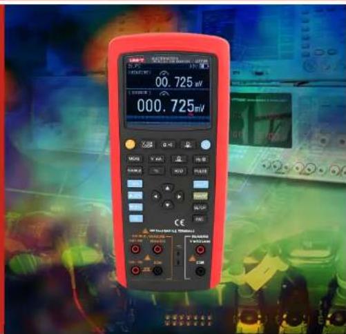
UT725
Multifunction
Process
Calibrator
UNI-T®
UT725 User Manual
Preface
Thank you for purchasing this brand new product. In order to use this product safely and correctly, please read this manual thoroughly, especially the safety notes.
After reading this manual, it is recommended to keep the manual at an easily accessible place, preferably close to the device, for future reference.
Limited Warranty and Liability
Uni-Trend guarantees that the product is free from any defect in material and workmanship within one year from the purchase date. This warranty does not apply to damages caused by accident, negligence, misuse, modification, contamination or improper handling. The dealer shall not be entitled to give any other warranty on behalf of Uni-Trend. If you need warranty service within the warranty period, please contact your seller directly.
Uni-Trend will not be responsible for any special, indirect, incidental or subsequent damage or loss caused by using this device.
UNI-T®
UT725 User Manual
Table of contents
- Overview 4
- Features 5
- Accessories 5
- Safety information 6
- Electrical symbols 7
- General specifications 7
- External structure 8
- Basic operations 11
- MEASURE mode 42
- MEASURE MODE 13
9.1 Millivolt measurement 13
9.2 Voltage measurement 14
9.3 Milliampere measurement 15
9.4 LOOP measurement 16
9.5 Resistance measurement 16
9.6 Pressure measurement 18 - TC measurement 21
- RTD measurement 23
- SOURCE mode 25
- Advanced applications 33
- Specifications 35
- Output specification 40
- Maintenance and Repair—44
UNI-T®
UT725 User Manual
1. Overview
UT725 is a handheld multifunction process calibrator with high accuracy and high performance. This meter can be used to measure and output multiple electrical and physical performances, the accuracy of measurement and output of DC current/voltage reaches up to 0.02%. Auto stepping and ramping function is used for fast linearity detection, the storage function makes users set up the system faster and more conveniently, and the data transfer function enables users to perform a fast communication test.
UT725 supports the processing of two signals, the upper screen can display test voltage, current (loop power supply), resistance and pressure, while the lower screen can display voltage, current, frequency, resistance, voltage, RTD and TC in the form of temperature.
| Function | Measurement | Output | Remark |
| DC voltage | 0~50V (Upper screen: ±30V) | 0~10V | Two-channel measurement |
| DC current | 0~24mA (Upper screen: ±24mA) | 0~24mA | Two-channel measurement |
| Frequency | 1.000Hz~100kHz | 0.20Hz~100kHz | |
| Resistance | 0~500Ω | 10~40000Ω | Two-channel measurement |
| DC millivolt | -10mV~500mV | -10mV~1100mV | Two-channel measurement |
| RTD | Pt100、Pt200、Pt500、Pt1000、Cu10、Cu50、Cu100、Pt100-392、Pt100-JIS、Ni120 | ||
| TC | R、S、K、E、J、T、N、B、L、U、XK、BP | ||
| Gas pressure | With pressure module | Two-channel measurement | |
| Others | Isolated loop power supply, stepping output, ramping output, adjustable range. | ||
UNI-T®
UT725 User Manual
2. Features
a) Up to 0.02% output and measurement accuracy
b) With percentage output function, different percentage values can be obtained by pressing corresponding
button
c) Auto stepping and ramping output for fast linearity detection.
d) Perform mA measurement at the same time that the loop power is provided to transmitter.
e) Measure and output 10 types of RTD and 12 types of TC signals.
f) Save frequently-used settings for future use.
g) Data transfer function enables users to perform a fast communication test.
h) Adjustable screen brightness.
i) Rechargeable Ni-MH battery.
3. Accessories
Open the package box and take out the device. Please check whether the following items are deficient or
damaged, and
contact your supplier immediately if they are.
| 1. UT725 | 1 piece |
| 2. Test probe | 2 pairs |
| 3. Afligator clips | 2 pairs |
| 4. K-type temperature probe | 1 piece |
| 5. User manual | 1 piece |
| 6. AA NI-MH battery | 6 piece |
| 7. Power adapter | 1 piece |
| 8. USB cable | 1 piece |
| 9. Cloth bag | 1 piece |
5
UNI-T®
UT725 User Manual
4. Safety information
Please follow the instructions in this user manual to use the meter, otherwise the protection provided by the meter may be impaired. "Warning" refers to potential hazard, "Attention" refers to the situation where would damage the calibrator or devices under test.

To avoid electric shock, damage, explosive gas ignition, please obey the followings:
- Please follow the instructions in this user manual to use the meter
- Check the meter before use, do not use a damaged calibrator.
- Check the connectivity and insulation of the test leads, replace any exposed test leads.
- When using the probes, user only hold the protection end of the probe.
- Do not exert a voltage with more than 50.0 V on any terminals and earth line
- If a voltage with more than 50.0 V is applied on any terminals, the factory certificate will be out of effect, moreover, the device will be damaged permanently.
- Correct terminals, modes, ranges must be used when it is on output status.
- To prevent the tested device from being damaged, choose a correct mode before connecting the testing lead.
- When connecting the leads, first connect the COM test probe and then connect the other probe. While disconnecting the lead, first disconnect the live probe and then disconnect the COM probe.
■ Do not open the calibrator case. - Before using the calibrator, please ensure that the battery door is tightly closed. Please refer to "Maintenance"
- When low battery indicator ☐ appears, replace or charge the battery as soon as possible to avoid wrong reading value which may cause electric shock. Before opening the battery door, first remove the calibrator from "Dangerous Zone".
- Please refer to "Maintenance".
■ Disassemble the test leads of the calibrator before opening the battery door.
6
UNI-T®
UT725 User Manual
UNI-T®
2. Buttons
Figure 3 shows the buttons of the meter, table 4 describes the functions of the meter.
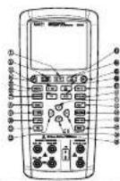
Figure 3 - The buttons of the meter
| No | Name | Description |
| 1 | -v) | Select resistance in upper screen, continuity measurement |
| 2 | V mA Loop | Select measurement function of millivolt voltage, millampers, loop current and others in upper screen. |
| 3 | Power cutoff | |
| 4 | V mA | Select measurement/output function of millivolt voltage, millampers, SIM and others in lower screen |
| 5 | MEAS | Switch the function of lower screen to measurement mode. |
| 6 | TC | Select measurement or output function of TC in lower screen. Consecutively short press this button to switch between different TC graduations. |
| 7 | SOURCE | Switch the functions of lower screen to output mode. |
9
UT725 User Manual
| 8 | 100% | When the lower screen is in output mode, short press to recall and output 100% value of the preset range. Long press to reset the 100% value. |
| 9 | ▲25% | When the lower screen is in output mode, press to increase output by 25% of preset range. |
| 10 | ▼25% | When the lower screen is in output mode, press to decrease output by 25% of preset range. |
| 11 | 0% | When the lower screen is in output mode, short press to recall and output 0% value of the preset range. Long press to reset the 0% value. |
| 12 | Enable the pulse output function. | |
| 13 | Select pressure measurement/output function in upper screen. Consecutively short press to switch between different pressure units. | |
| 14 | Select pressure measurement/output function in lower screen. Consecutively short press to switch between different pressure units. | |
| 15 | Adjust screen brightness. | |
| 16 | RTD | Select measurement/output function of RTD in lower screen. Consecutively short press to switch between different RTD graduations. |
| 17 | HzΩ | Select frequency in lower screen, resistance measurement/output function. |
| 18 | PULSE | Select pulse in lower screen, measurement/output function of switch quantify. |
| 19 | ▲ | Direction key (up), used to revise the output value. |
| 20 | AWR | When the lower screen is in output mode, short press to enable ramping output function. |
| 21 | RANGE | When the lower screen is in output mode, consecutively short press to switch the range for current range. |
| 22 | SETUP | Setup button, long press to enter the setup interface of system parameter. |
| 23 | ESC | Exit button |
| 24 | Direction key (right) | |
| 25 | Direction key (left) |
10
UNI-T®
UT725 User Manual
- LCD display
| Symbol | Description |
| SOURCE | Source output mode |
| MESUER | Measurement mode |
| ▲ | Data adjustment |
| SIM | Transmitter output simulation |
| LOOP | loop measurement |
| CCC1 | Battery level |
| LOAD | Overload |
| AW2 | Ramp/step output |
| PC | Remote control |
| APO | Auto power on/off |
8. Basic operations
This section introduces some basic operations about the meter.
1. Press and hold ⏻ for more than 2s to power on the meter, then the model of the meter will be displayed on LCD.
2. In any function interface, long press SETUP to enter system setup menu. Press arrow button to set parameter, short press ESC to exit setup menu.
11
UT725 User Manual
UNI-T®
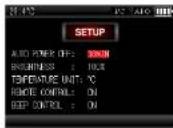
Figure 1 - System setup
1) Auto power off
Press ▼▲ to select AUTO POWER OFF, press ◀▶ to set up the auto power off time. The AUTO POWER OFF time will start when no button is pressed, the counting will restart if any button is pressed. The maximum AUTO POWER OFF time is 30 minutes, "0" represents auto power off is disabled.
2) Brightness
Press ▼▲ to select BRIGHTNESS, press ◀▶ to adjust screen brightness. In setup interface, press 🔒 to adjust brightness quickly.
3) Remote control
Press ▼▲ to select REMOTE CONTROL, press ◀▶ to set up for remote PC control.
4) Button beep control
Press ▼▲ to BEEP CONTROL, press ◀▶ to set up button sound. "Beep" once enables button sound, "Beep" twice disables button sound.
5) Temperature unit
Press ▼▲ to select TEMPERATURE UNIT, press ◀▶ to switch between ℃ and ℉. "Beep" once enables button sound, "Beep" twice disables button sound.
12
UNI-T®
UT725 User Manual
9. MEASURE mode
9.1 Millivolt measurement
Upper-screen millivolt measurement
Consecutively short press [70] to switch between mV, V, mA, LOOP until mV is selected.
Figure 4 - Measurement interface
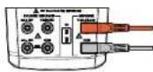
Figure 5 - Connection
Lower-screen millivolt measurement
In measurement mode (If the meter is in output mode, short press MEAS to switch to measurement mode),
consecutively short press to switch between mV, V, mA until mV is selected.
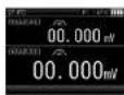
Figure 6 - Measurement interface
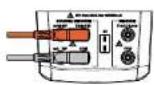
Figure 7 - Connection
UNI-T®
UT725 User Manual
9.2 Voltage measurement
Upper- screen voltage measurement
Consecutively short press switch between mV, V, mA, LOOP until V is selected.
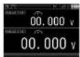
Figure 8 - Measurement interface
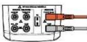
Figure 9 - Connection
Lower-screen voltage measurement
In measurement mode (If the meter is in output mode, short press MEAS to switch to measurement mode), short press VmA to switch between mV, V, mA until V is selected.
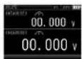
Figure 10 - Measurement interface
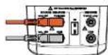
Figure 11 - Connection
UNI-T®
UT725 User Manual
9.3 Milliampere measurement
Upper-screen milliampere measurement
Consecutively short press , mA to switch between mV, V, mA, LOOP until mA is selected.
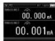
Figure 12 - Measurement interface
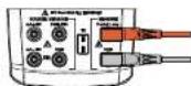
Figure 13 - Connection
Lower-screen milliampere measurement
In measurement (If the meter is in output mode, short press MEAS to switch to measurement mode), consecutively short press V mA to switch between mV, V, mA until mA is selected.
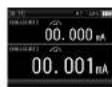
Figure 14 - Measurement interface
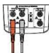
Figure 15 - Connection
UNI-T®
UT725 User Manual
9.4 LOOP measurement
LOOP measurement function can start the 24V power supply (inside the meter) connected with current measurement circuit in series, this enables users to test the transmitter without power supply of two-wire transmitter on site. Consecutively short press [5] to switch between mV, V, mA. LOOP until LOOP measurement function is selected.
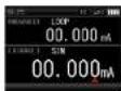
Figure 16 - Measurement interface
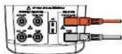
Figure 17 - Connection
9.5 Resistance measurement
Upper-screen resistance measurement
Consecutively short press =8 to switch between resistance measurement function and continuity measurement function until resistance measurement is selected.
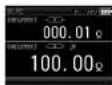
Figure 18 - Measurement Interface
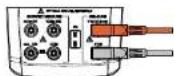
Figure 19 - Connection
UNI-T®
UT725 User Manual
Lower-screen resistance measurement
In measurement mode (If the meter is in output mode, short press MEAS to switch to measurement mode), short press Fe_2O to switch between 2/3/4-wire resistance measurement function and frequency measurement function until resistance measurement is selected. Lower-screen resistance measurement supports 2/3/4-wire connection method (Figure 22).
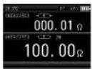
Figure 20 - Measurement interface
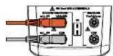
Figure 19 - Connection
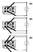
Figure 22 - 2/3/4-wire connection methods
Continuity measurement
Consecutively short press [ - ] to switch between continuity measurement function and resistance measurement function until continuity measurement is selected.
UNI-T®
UT725 User Manual
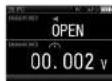
Figure 23 - Measurement interface
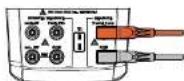
Figure 24 - Connection
Note: The buzzer sounds when the measured resistance value is less than 50Ω.
9.6 Pressure measurement
Upper-screen pressure measurement
Short press 🔒 to start pressure measurement function.
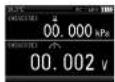
Figure 25 - Measurement interface
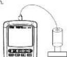
Figure 26 - Connection
Lower-screen pressure measurement
In measurement mode (if the meter is in output mode, short press MEAS to switch to measurement mode), short press ♀ to start pressure measurement function.
UNI-T®
UT725 User Manual
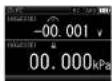
Figure 27 - Measurement interface
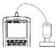
Figure 28 - Connection
Note: The pressure measurement is with 5-digit display, the specific range depends on pressure transducer. Pressure measurement cannot be performed in upper and lower screen at the same time, upper screen or lower screen will display “----” if selecting pressure measurement for both upper and lower screen. Press 9% to clear.
Frequency measurement
In measurement mode (If the meter is in output mode, short press MEAS to switch to measurement mode), consecutively short press 10 to switch between frequency measurement function and 2/3/4-wire resistance measurement function until frequency measurement is selected.
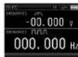
Figure 29 - Measurement interface
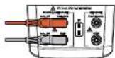
Figure 30 - connection
UNI-T®
UT725 User Manual
Pulse measurement
In measurement mode (If the meter is in output mode, short press MEAS to switch to measurement mode), consecutively short press PULSE to switch between pulse measurement function and switch measurement function until pulse measurement is selected.
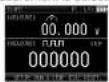
Figure 31 - Measurement interface
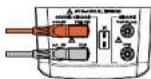
Figure 32 - connection
Note: Press [SETUP] to start or stop pulse measurement, press [ESC] to reset pulse measurement function, the current pulse counting will be cleared.
Switch quantity measurement
In measurement mode (If the meter is in output mode, short press PEAS to switch to measurement mode), consecutively press PULSE to switch between switch quantity measurement and pulse measurement until switch quantity measurement is selected.
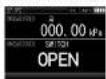
Figure 33 - Measurement interface
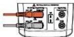
Figure 34 - connection
Note: Minimum duration for open/close test is 500ms
UNI-T®
UT725 User Manual
10. TC measurement
The meter supports temperature measurement of following thermal couples: R, S, K, E, J, T, N, B, L, U,
XK, BP, etc. The temperature ranges and characteristics of these thermal couples are shown in Table 5.
| Graduation | Positive conductor | Negative conductor | Temperature range (°C) |
| R | Platinum (13% rhodium) | Platinum | 0~1767 |
| S | Platinum (10% rhodium) | Platinum | 0~1767 |
| K | Chromel | Chromel | -100~1372 |
| E | Chromel | Constantan | -50~1000 |
| J | Iron | Constantan | -60~1200 |
| T | Copper | Constantan | -100~400 |
| N | Nickel - Chromium - Silicon | Nickel - Silicon - Magnesium | -200~1300 |
| B | Platinum (30% rhodium) | Platinum (6% rhodium) | 600~1820 |
| L | Iron | Constantan | -200~900 |
| U | Copper | Constantan | -200~400 |
| XK | 95 % lungslen + 5 % rhenium | 80 % lungslen + 20 % rhenium | -200~800 |
| BP | 90.5 % nickel+ 9.5 % chromium | 56 % copper + 44 % nickel | 0~2500 |
UNI-T®
UT725 User Manual
In measurement mode (If the meter is in output mode, short press MEAS switch to measurement mode), short press TC to start TC temperature measurement function.
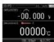
Figure 35 - Measurement interface
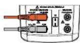
Figure 36 - connection
- Short press SETUP to set manual CJC value, press the direction button to adjust manual CJC value, short press ESC again to complete the input of manual CJC value.
- Short press SETUF to stop setting manual CJC value and switch to auto CJC mode.
Note: If the temperature environment of meter differs from that of thermal couple, please wait for more than one minute to stabilize the plug temperature after connecting TC input/output line.
UNI-T®
UT725 User Manual
11. RTD measurement
The meter supports temperature measurement of following RTD: Pt100-385, Pt100-392, Pt100-JIS, Pt200, Pt500, Pt1000, Cu10, Cu50, Cu100, Ni120, etc. The temperature ranges and characteristics of these RTD are shown in Table 6.
| Graduation | Material | Temperature range (°C) |
| PT100-385 | Platinum | -200~650 |
| PT100-392 | Platinum | -200~630°C |
| PT100-JIS | Platinum | -200~630°C |
| PT200-385 | Platinum | -200~630 |
| PT500-385 | Platinum | -200~630 |
| PT1000-385 | Platinum | -200~650 |
| Cu10 | Copper | -100~260 |
| Cu50 | Copper | -50~150 |
| Cu100 | Copper | -50~150 |
| Ni120 | Copper | -80~260 |
UNI-T®
UT725 User Manual
In measurement mode (If the meter is in output mode, short press MEAS to switch to measurement mode), short press RTD to start RTD temperature measurement function.
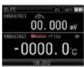
Figure 37 - Measurement interface
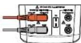
Figure 38 - Two-wire connection
Note: Consecutively short press SETUP to switch between 2-wire, 3-wire and 4-wire connection.
UNI-T®
UT725 User Manual
12. SOURCE mode
Millivolt output
In output mode (If the meter is in measurement mode, short press SOURCE to switch to output mode), consecutively short press VmA to switch between mV, V, mA, and SIM until mV is selected.
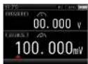
Figure 39 - Output interface
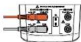
Figure 40 - Connection
Note: Press right or left arrow key to change the modified bit of output value, press up or down arrow key to modify the output value. The port outputs corresponding millivolt value in real time when output value is changed.
Voltage output
In output mode (If the meter is in measurement mode, short press SOURCE to switch to output mode), short press V mA to switch between mV, V, mA and SIM until V is selected.
UNI-T®
UT725 User Manual

Figure 41 - Output interface
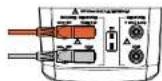
Figure 42 - Connection
Note: Press right or left arrow key to change the modified bit of output value, press up or down arrow key to modify output value. The port outputs corresponding voltage value in real time when output value is changed.
Milliampere output
In output mode (If the meter is in measurement mode, short press SOURCE to switch to output mode), consecutively short press V mA to switch between mV, V, mA and SIM until mA is selected.
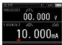
Figure 43 - Output interface
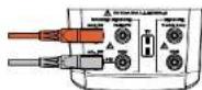
Figure 44 - Connection
UNI-T®
UT725 User Manual
Note:
- Press right or left arrow key to change the modified bit of output value, press up or down arrow key to modify output value. The port outputs corresponding current value in real time when output value is changed.
- The output value flickers and "LOAD" appears on the screen if output load is too high, please check whether the connection is correct for safety in such situation.
Passive current output (SIM)
In output mode (If the meter is in measurement mode, short press SOURCE to switch to output mode), consecutively short press V mA to switch between mV, V, mA and SIM until SIM is selected.
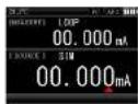
Figure 45 - Output interface
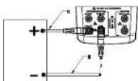
Figure 46 - Connection
Note:
- Press right or left arrow key to change the modified bit of output value, press up or down arrow key to modify output value. The port outputs corresponding current value in real time when output value is changed.
- The output value flickers and "LOAD" appears on the screen if output load is too high, please check whether the connection is correct for safety in such situation.
27
UNI-T®
UT725 User Manual
Resistance output
In output mode (If the meter is measurement mode, short press SOURCE to switch to output mode), consecutively short press to switch between resistance output and frequency output until resistance output is selected.
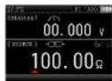
Figure 47 - Output interface
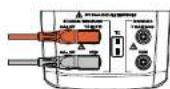
Figure 48 - Connection
Note:
- Press right or left arrow key to change the modified bit of output value, press up or down arrow key to modify output value. The port outputs corresponding resistance value in real time when output value is changed.
- Excitation current is required for resistance output. The output value flickers and "Exl HI"/"Exl LO" appears on the screen if excitation current is too high/low, please check the excitation current in such situation.
Frequency output
In output mode (If the meter is in measurement mode, short press SOURCE to switch to output mode), consecutively short press 2 to switch between frequency output and resistance output until frequency output is selected.
28
UNI-T®
UT725 User Manual
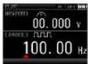
Figure 49 - Output interface
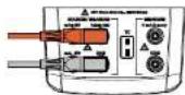
Figure 50 - Connection
Note:
- Short press RANGE to switch between 200Hz, 2000Hz, 20kHz and 100kHz.
- Short press SETUP to enter the interface of setting frequency amplitude, in this interface, press direction key to adjust frequency amplitude, short press SETUP again to make the adjustment valid, short press ESC to abort the adjustment.
Pulse output
In output mode (If the meter is in measurement mode, short press SOURCE to switch to output mode),
consecutively short press PULSE to switch between pulse output and switch quantity output until pulse output is selected.
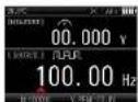
Figure 51 - Output interface
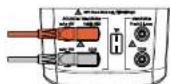
Figure 52 - Connection
UNI-T®
UT725 User Manual
Note:
- Press RANGE to switch between 100Hz, 1kHz and 10kHz.
- Short press SETUP to enter the status of editing pulse number, in this status, press direction key to edit the number of pulse, short press SETUP again to complete the setting of pulse number and then immediately enter the status of modifying pulse amplitude, in this status, press direction key to modify pulse amplitude, short press SETUP to complete the modification of pulse amplitude, the meter starts outputting a preset number of pulses according to the preset frequency and amplitude.
Switch quantity output
In output mode (If the meter is in measurement mode, short press SOURCE to switch to output mode), consecutively short press PULSE to switch between pulse output and switch quantity output until switch quantity output is selected.
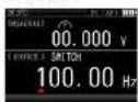
Figure 53 - Output interface
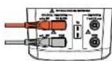
Figure 54 - Connection
Note:
- Short press RANGE to switch between 100Hz, 1kHz, 10kHz, 100kHz.
- Press right or left arrow key to change the modified bit of output value, press up or down arrow key to modify output value. The port outputs corresponding switch signal in real time when output value is changed.
UNI-T®
UT725 User Manual
TC output
The meter supports simulating temperature output of following thermal couples: R, S, K, E, J, T, N, B, L, U, XK, BP, etc.
In output mode (If the meter is in measurement mode, short press SOURCE to switch to output mode), short press TC to start TC temperature output function.
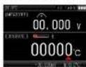
Figure 55 - Output interface
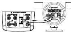
Figure 56 - Connection
Note:
- Short press [TC] to switch between different thermal couples.
- Short press SETUP to enter the interface of modifying CJC value of thermal couple, in this interface, press direction key to modify CJC value, press SETUP again to complete the input of manual CJC value.
- Press ESC to switch to auto CJC mode.
RTD output
In output mode (If the meter is measurement mode, short press SOURCE to switch to output mode), short press RTD to start RTD output function.
UNI-T®
UT725 User Manual
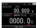
Figure 57 - Output interface
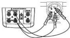
Figure 58 - Connection
Note:
- Consecutively short press RTD to switch between different RTD.
- 3-wire and 4-wire terminals are for measurement only (not for output simulation). The meter can simulate the output of a
2-wire RTD. If a 3-wire or 4-wire transmitter needs to be connected, use stacking cables to provide additional wiring. - "Exl HI"/"Exl LO" appears on the screen if excitation current of the measured device exceeds the limit.
Remote mode
Based on the instruction, turn on the PC control functionality, set the parameter of serial interface on PC and send the protocol command to control UT725.
Please access to UNI-T official website to download the communication protocol.
UNI-T®
UT725 User Manual
13. Advanced applications
Percentage output
Stepping operation and percentage display can be used after the values of 0% and 100% are set. Some values of the meter have been set before delivering. The table below lists the factory setting.
| Output functions | 0% value | 100% value | Output functions | 0% value | 100% value |
| Voltage | 0 V | 10 V | Thermocouple type R | 0 °C | 1767 °C |
| Millivolt | 0 mV | 100 mV | Thermocouple type S | 0°C | 1767 °C |
| Current | 4 mA | 20 mA | Thermocouple type B | 600 °C | 1920 °C |
| Resistance 400Ω | 0 Ω | 400 Ω | Thermocouple type L | -200 °C | 900 °C |
| Resistance 4000Ω | 0 Ω | 4000 Ω | Thermocouple type U | -200 °C | 400 °C |
| Resistance 40KΩ | 0Ω | 40000Ω | Thermocouple type XK | -200 °C | 800 °C |
| Frequency 200Hz | 0 Hz | 200 Hz | Thermocouple type BP | 0 °C | 2500 °C |
| Frequency 2000Hz | 200 Hz | 2000 Hz | Pt100-385 | -200 °C | 850 °C |
| Frequency 20 kHz | 2 kHz | 20 kHz | Pt100-392 | -200 °C | 630 °C |
| Thermocouple type J | -200 °C | 1200 °C | Pt100-JIS | -200 °C | 630 °C |
| Thermocouple type K | -200 °C | 1372 °C | Pt200-385 | -200 °C | 630 °C |
| Thermocouple type T | -250 °C | 400 °C | Pt500-385 | -200 °C | 630 °C |
| Thermocouple type E | -200 °C | 1000 °C | Pt1000-385 | -200 °C | 630 °C |
33
UNI-T®
UT725 User Manual
| Cu10 | -100°C | 260°C | Cu50 | -50°C | 150°C |
| Output function | 0% value | 100% value | Cu100 | -50°C | 150°C |
| Ni120 | -80°C | 260°C |
In output mode, short press 0%, 100%, ▲25%, ▼25% to quickly output the value of corresponding percentage in current function.
0% and 100% values can be set as below:
-
Press direction key to adjust output value of current output function, long press [100%] until the buzzer beeps, the current output value is set as new 100% value.
-
Press direction key to adjust output value of current output function, long press [0%] until the buzzer beeps, the current output value is set as new 0% value.
Note:
-
100% value must be greater than 0% value.
-
Short press ▲25% to increase the output by 25% of the difference between 100% value and 0%. Short press ▼25% to decrease the output by 25% of the difference between 100% value and 0%.
-
Short press ▲25%, ▼25% to adjust output value (0% value < output value <100% value).
Ramping output
The auto ramping function allows you to continuously apply a varying signal from the meter to the transmitter. When you press AMr^F , the meter will generate a continuous and repeating 0% - 100% - 0% ramping output. Three types of ramping waveforms are available:
A 0%-100%-0% 45-second smooth ramp
M 0%-100%-0% 20-second smooth ramp
0%-100%-0% 25% step ramp, pausing for 5s at each step
Press any key to exit the ramping output function.
34
UNI-T®
UT725 User Manual
14. Specifications
All specifications are based on one-year calibration period and applied to a temperature range of +18°C →+28°C unless otherwise specified. All specifications are assumed to obtain after 30 minutes operation.
Input specifications
| Specifications | Range | Resolution | Accuracy |
| DC voltage | 50mV | 0.001mV | ±(0.02%+10) |
| 500mV | 0.01mV | ±(0.02%+5) | |
| 30V (Upper) | 1mV | ±(0.02%+2) | |
| 50V (Lower) | 0.001V | ±(0.02%+2) | |
| DC current | 20mA@0-24mA | 0.001mA | ±(0.02%+2) |
| 20mA(loop) @0-24mA | 0.001mA | ±(0.02%+2) | |
| Resistance | 500Ω | 0.01Ω | ±(0.05%+10) |
| 5000Ω | 0.1Ω | ±(0.05%+10) | |
| Frequency | 100Hz | 0.001Hz | ±(0.01%+1) |
| 1kHz | 0.01Hz | ±(0.01%+1) | |
| 10kHz | 0.1Hz | ±(0.01%+1) | |
| 100kHz | 1Hz | ±(0.01%+1) |
35
UNI-T®
| Thermocouple R (TC) | 0~500 | 1°C/1°F | ±1.8°C |
| 500-1767 | ±1.5°C | ||
| Thermocouple S (TC) | 0-500 | 1°C/1°F | ±1.8°C |
| 500-1767 | ±1.5°C | ||
| Thermocouple K (TC) | -100-0 | 0.1°C | ±1.2°C |
| 0-1372 | ±0.8°C | ||
| Thermocouple E (TC) | -50-0 | 0.1°C | ±0.9°C |
| 0-1000 | ±1.5°C | ||
| Thermocouple J (TC) | -60-0 | 0.1°C | ±1.0°C |
| 0-1200 | ±0.7°C | ||
| Thermocouple T (TC) | -100-0 | 0.1°C | ±1.0°C |
| 0-400 | ±0.7°C | ||
| Thermocouple N (TC) | -200-0 | 0.1°C | ±1.5°C |
| 0-1300 | ±0.9°C |
36
UNI-T®
UT725 User Manual
| Thermocouple B (TC) | 600~800 | 1°C/1°F | ±2.2°C |
| 800~1000 | ±1.8°C | ||
| 1000~1820 | ±1.4°C | ||
| Thermocouple L (TC) | -200~0 | 0.1°C/0.1°F | ±0.85°C |
| 0~900 | ±0.7°C | ||
| Thermocouple U (TC) | -200~0 | 0.1°C/0.1°F | ±1.1°C |
| 0~400 | ±0.75°C | ||
| Thermocouple XK (TC) | -200~100 | 0.1°C/0.1°F | ±0.5°C |
| -100~800 | ±0.6°C | ||
| Thermocouple BP (TC) | 0~800 | 0.1°C/0.1°F | ±1.2°C |
| 800~2500 | ±2.5°C | ||
| RTD Pt100 (RTD) | -200~850 (2W/3W) | 0.1°C/0.1°F | ±0.4°C |
| -200~850 (4W) | ±0.3°C | ||
| Pt200 (RTD) | -200~250 (2W/3W) | 0.1°C/0.1°F | ±0.3°C |
| -200~250 (4W) | ±0.2°C | ||
| 250~630 (2W/3W) | ±1.6°C | ||
| 250~630 (4W) | ±0.8°C |
37
UNI-T®
UT725 User Manual
| Pt500 (RTD) | -200~500 (2W/3W) | 0.1°C/0.1°F | ±0.6°C |
| -200~500 (4W) | ±0.3°C | ||
| 500~630 (2W/3W) | ±0.9°C | ||
| 500~630 (4W) | ±0.4°C | ||
| Pt1000 (RTD) | -200~650 (2W/3W) | 0.1°C/0.1°F | ±0.3°C |
| -200~650 (4W) | ±0.15°C | ||
| Cu10 (RTD) | -100~260 | 0.1°C/0.1°F | ±1.8°C |
| Cu50 (RTD) | -50~150 (2W/3W) | 0.1°C/0.1°F | ±0.8°C |
| -50~150 (4W) | ±0.5°C | ||
| Cu100 (RTD) | -50~150 (2W/3W) | 0.1°C/0.1°F | ±0.4°C |
| -50~150 (4W) | ±0.25°C | ||
| Pt100-392 (RTD) | -200~630 (2W/3W) | 0.1°C/0.1°F | ±0.5°C |
| -200~630 (4W) | ±0.3°C | ||
| Pt100-JIS (RTD) | -200~630 (2W/3W) | 0.1°C/0.1°F | ±0.5°C |
| -200~630 (4W) | 0.1°C/0.1°F | ±0.3°C |
38
UNI-T®
UT725 User Manual
| Ni120 (RTD) | -80~260 (2W/3W) | 0.1°C/0.1°F | ±0.3°C |
| -80~260 (4W) | ±0.2°C | ||
| Switch quantity measurement | Minimum duration for open/close test is 500ms | CLOSE/OPEN | |
| Continuity detection | 500Ω | 0.01Ω | Beeps at ≤50Ω |
| Pulse | 0~15kHz (0~100000) | ||
Note:
1. For 2-wire measurement of resistance, the error does not include the conductor resistance.
2. For 3-wire measurement of resistance, a matched test lead should be used, the conductor resistance is not greater than 25 .
3. For 4-wire measurement of resistance, the conductor resistance is not greater than 100Ω.
4. The sensitivity of frequency measurement: Vpp≥1V; waveform: rectangular wave, sine wave, triangular wave, etc.
5. The accuracy of pressure measurement is based on the accuracy grade of pressure module.
UNI-T®
UT725 User Manual
- Output specification
| Specifications | Range | Resolution | Accuracy |
| DC voltage | 100mV | 0.001mV | ±(0.02%+10) |
| 1V | 0.01mV | ±(0.02%+10) | |
| 10V | 0.0001V | ±(0.02%+10) | |
| DC current | 20mA @ 0 - 24mA | 0.001mA | ±(0.02%+2) |
| 20mA (SIM) @ 0 - 24mA | 0.001mA | ±(0.02%+2) | |
| Resistance | 400Ω | 0.01Ω | ±(0.02%+8) |
| 4000Ω | 0.1Ω | ±(0.05%+10) | |
| 40kΩ | 1Ω | ±(0.1%+40) | |
| Frequency | 200Hz | 0.01Hz | ±(0.01%+1)(±3dig) |
| 2000Hz | 0.1Hz | ±(0.01%+1)(±3dig) | |
| 20kHz | 1Hz | ±(0.01%+1)(±3dig) | |
| 100kHz | 10Hz | ±5dig | |
| Pulse | 100Hz (1~100000) | 1cyc | ±2dig |
| 1kHz (1~100000) | ±2dig | ||
| 10kHz (1~100000) | ±2dig |
UNI-T®
UT725 User Manual
| Switch quantity | 100Hz(1Hz~110Hz) | 0.01Hz | ±2dig |
| 1kHz(0.1kHz~1.1kHz) | 0.1Hz | ±2dig | |
| 10kHz(1kHz~11kHz) | 1Hz | ±2dig | |
| 100kHz(10kHz~110kHz) | 10Hz | ±2dig | |
| Thermocouple R (TC) | 0~100°C | 1°C/1°F | ±1.5°C |
| 100~1767°C | ±1.2°C | ||
| Thermocouple S (TC) | 0~100°C | 1°C/1°F | ±1.5°C |
| 100~1767°C | ±1.2°C | ||
| Thermocouple K (TC) | -200~100°C | 0.1°C/0.1°F | ±0.6°C |
| -100~400°C | ±0.5°C | ||
| 400~1200°C | ±0.7°C | ||
| 1200~1372°C | ±0.9°C | ||
| Thermocouple E (TC) | -200~100°C | 0.1°C/0.1°F | ±0.6°C |
| -100~600°C | ±0.5°C | ||
| 600~1000°C | ±0.4°C |
UNI-T®
UT725 User Manual
| Thermocouple J (TC) | -200~-100°C | 0.1°C/0.1°F | ±0.6°C |
| -100~800°C | ±0.5°C | ||
| 800~1200°C | ±0.7°C | ||
| Thermocouple T (TC) | -250~400°C | 0.1°C/0.1°F | ±0.6°C |
| Thermocouple N (TC) | -200~-100°C | 0.1°C/0.1°F | ±1.0°C |
| -100~900°C | 0.1°C/0.1°F | ±0.7°C | |
| 900~1300°C | 0.1°C/0.1°F | ±0.8°C | |
| Thermocouple B (TC) | 600~800°C | 1°C/1°F | ±1.5°C |
| 800~1820°C | 1°C/1°F | ±1.1°C | |
| Thermocouple L (TC) | -200~0°C | 0.1°C/0.1°F | ±0.85°C |
| 0~900°C | 0.1°C/0.1°F | ±0.7°C | |
| Thermocouple U (TC) | -200~0°C | 0.1°C/0.1°F | ±1.1°C |
| 0~400°C | 0.1°C/0.1°F | ±0.75°C | |
| Thermocouple XK (TC) | -200~-100°C | 0.1°C/0.1°F | ±0.5°C |
| -100~800°C | 0.1°C/0.1°F | ±0.6°C |
UNI-T®
UT725 User Manual
| Thermocouple BP (TC) | 0~800°C | 0.1°C/0.1°F | ±1.2°C |
| 800~2500°C | 0.1°C/0.1°F | ±2.5°C | |
| Pt100-385 (RTD) | -200~800°C | 0.1°C/0.1°F | ±0.33°C |
| Pt100-392 (RTD) | -200~630°C | 0.1°C/0.1°F | ±0.3°C |
| Pt200-385 (RTD) | -200~250°C | 0.1°C/0.1°F | ±0.2°C |
| 250~630°C | 0.1°C/0.1°F | ±0.8°C | |
| Pt100-JIS (RTD) | -200~630°C | 0.1°C/0.1°F | ±0.3°C |
| Pt500-385 (RTD) | -200~500°C | 0.1°C/0.1°F | ±0.3°C |
| 500~630°C | 0.1°C/0.1°F | ±0.4°C | |
| Pt1000-385 (RTD) | -200~100°C | 0.1°C/0.1°F | ±0.2°C |
| 100~630°C | 0.1°C/0.1°F | ±0.2°C | |
| RTD Cu10 | -100~260°C | 0.1°C/0.1°F | ±1.8°C |
| RTD Cu50 | -50~150°C | 0.1°C/0.1°F | ±0.5°C |
| RTD Cu100 | -50~150°C | 0.1°C/0.1°F | ±0.25°C |
| RTD Ni120 | -80~260°C | 0.1°C/0.1°F | ±0.2°C |
UNI-T®
UT725 User Manual
Note:
- Temperature coefficient for -10°C\~18°C and +28°C\~55°C: ±0.005%FS/°C.
- Maximum load of DC voltage output: 1mA or 10kΩ, whichever is lower load.
3.Maximum load resistance of DC current output: 1000Ω@20mA - Frequency output: rectangular wave with a duty ratio of 50% approximately.
16. Maintenance and Repair
Warning: Make sure that the power is off before opening the rear cover of the calibrator or battery cover, and that he probe is away from input terminal and tested circuit.
1. General maintenance and repair
* Clean the case by damp cloth and mild detergent, do not use abrasives or solvents.
* If there is any malfunction, stop using the calibrator and send it for repair.
* Please ensure that the calibrator is repaired by professionals or designated repair center.
* Calibrate the meter once a year to ensure its performance.
* If the meter is not in use, turn off the power. If the meter is not in use for a long time, please take out the batteries.
* Ensure that the instrumentation is free from moisture, high temperature and strong electromagnetic fields.
- Install or replace the battery (Figure 59)
NOTE: When the battery power display (☐), it means the rest of battery power is less than 20%, to ensure that the calibrator can work normally, please replace the battery in time, otherwise the measurement accuracy might be affected. Please replace the old battery by 1.5V alkaline battery or 1.2V NI-MH battery.
UNI-T®
UT725 User Manual
UT725 User Manual
UNI-T®
The contents of this manual are subject to change without notice.
UNI-T
UNI-TREND TECHNOLOGY (CHINA) CO., LTD.
No. 6, Gong Ye Bei 1st Road,
Songshan Lake National High-Tech Industrial
Development Zone, Dongguan City,
Guangdong Province, China
- UNI-T®
- UT725
- Preface
- Limited Warranty and Liability
- Table of contents
- Overview
- Features
- Accessories
- Safety information
- Buttons
- Basic operations
- 1) Auto power off
- 2) Brightness
- 3) Remote control
- 5) Temperature unit
- MEASURE mode
- Millivolt measurement
- Voltage measurement
- Milliampere measurement
- Lower-screen milliampere measurement
- LOOP measurement
- Resistance measurement
- Lower-screen resistance measurement
- Continuity measurement
- Pressure measurement
- Lower-screen pressure measurement
- Frequency measurement
- Pulse measurement
- TC measurement
- RTD measurement
- SOURCE mode
- Note:
- Passive current output (SIM)
- Resistance output
- Frequency output
- Pulse output
- Switch quantity output
- TC output
- RTD output
- Remote mode
- Advanced applications
- Percentage output
- 0% and 100% values can be set as below:
- Specifications
- Maintenance and Repair
- UNI-T
Brand : Uni-T
Model : UT725
Category : Measurement