
ARC-1230WNH - Air conditioner Whynter - Free user manual and instructions
Find the device manual for free ARC-1230WNH Whynter in PDF.


| Product Type | Portable Air Conditioner with Heat Pump |
| Model | ARC-1230WNH |
| Cooling Capacity | 14,000 BTU (SACC 12,000 BTU) |
| Heating Capacity | 12,000 BTU |
| Coverage Area | 600 sq. ft. |
| Noise Level (Low/Med/High) | 42.5 / 52.6 / 56.8 dB |
| Fan Speeds | Continuous, Auto, Low, Medium, High |
| Temperature Range (Cooling) | 60°F - 86°F |
| Temperature Range (Heating) | 60°F - 86°F |
| Timer | Up to 24 hours |
| Refrigerant | R32 |
| Power Consumption | 1300W |
| Power Supply | 115V / 60Hz |
| Amps | 11.9 A |
| Dimensions (W x D x H) | 19.5" x 16.7" x 32.5" |
| Net Weight | 77.2 lbs |
| Control Methods | Control Panel, Remote Control, Wireless App |
| Special Features | Inverter Technology, Dual Hose (Hose-in-Hose), Auto Swing, I Sense, Sleep Mode, Auto Restart, Filter Indicator |
| Filter Type | Washable Pre-Filter |
| Maintenance Interval | Clean filter every 2 weeks |
| Warranty | 1 Year Parts, 3 Years Compressor |
| Safety Features | Overload Protection, Auto Restart, L.C.D.I. Power Cord |
Frequently Asked Questions - ARC-1230WNH Whynter
User questions about ARC-1230WNH Whynter
0 question about this device. Answer the ones you know or ask your own.
Ask a new question about this device
Download the instructions for your Air conditioner in PDF format for free! Find your manual ARC-1230WNH - Whynter and take your electronic device back in hand. On this page are published all the documents necessary for the use of your device. ARC-1230WNH by Whynter.
USER MANUAL ARC-1230WNH Whynter
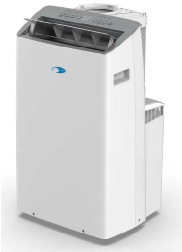
Whynter NEX Inverter Dual Hose Portable Air Conditioner with Wireless & LCD Remote
MODEL: ARC-1030WN / ARC-1230WN / ARC-1230WNH
natural_image
Exterior view of a white industrial air conditioner unit with control panel and ventilation slots (no visible text or symbols)Congratulations on your new Whynter product. To ensure proper operation, please read this Instruction Manual carefully before using this product. Keep this manual in a safe place for future reference.
Thank you for choosing Whynter. Please follow the instructions provided in this user manual to obtain the very best performance from your portable air conditioner. We trust that your Whynter portable air conditioner will provide the performance and reliability that we stand for.
Please keep this user manual in a safe place for future reference.
natural_image
Symbol of a trash bin with crossed x and y lines, no text or numbers presentThis symbol on the product or its packaging indicates that this appliance cannot be treated as normal domestic trash, but must be handed in at a collection point for recycling electric and electronic appliances. Your contribution to the correct disposal of this product protects the environment.
Further information about the recycling of this product can be obtained from your local municipal authority.
Supplier's Declaration of Conformity 47 CFR § 2.1077 Compliance Information
Responsible Party - U.S. Contact Information
Brand: Whynter
Company Name: Whynter LLC.
Address: 3320 E Birch Street, Brea CA 92821
Internet contact information: https://www.whynter.com
FCC Compliance Statement
This device complies with Part 15 of the FCC Rules. Operation is subject to the following two conditions: (1) This device may not cause harmful interference, and (2) this device must accept any interference received, including interference that may cause undesired operation.
Table of Contents
| PAGE | |
| SAFETY PRECAUTIONS | 4 |
| PREPARATION | 10 |
| INTRODUCTION / TECHNICAL DATA | 11 |
| ACCESSORIES | 12 |
| WINDOW KIT INSTALLATION | 12 - 14 |
| CONTROL PANEL | 15 - 16 |
| OPERATION INSTRUCTIONS | 17 - 18 |
| REMOTE CONTROL | 19 - 20 |
| CLEANING AND MAINTENANCE | 20 - 21 |
| TROUBLESHOOTING | 22 - 23 |
| WARRANTY | 24 |
SAFETY PRECAUTIONS
Read Safety Precautions Before Operation and Installation
To prevent death or injury to the user or other people and property damage, the following instructions must be followed. Incorrect operation due to ignoring of instructions may cause death, harm or damage.
- Installation must be performed according to the installation instructions. Improper installation can cause water leakage, electrical shock, or fire.
- Use only the included accessories and parts, and specified tools for the installation. Using non-standard parts can cause water leakage, electrical shock, fire, and injury or property damage. Make sure that the outlet you are using is grounded and has the appropriate voltage.
• The power cord is equipped with a three-prong grounding plug to protect against shock.
• Voltage information can be found on the nameplate of the unit. - Your unit must be used in a properly grounded wall receptacle. If the wall receptacle you intend to use is not adequately grounded or protected by a time delay fuse or circuit breaker (the fuse or circuit breaker needed is determined by the maximum current of the unit. The maximum current is indicated on the nameplate located on unit), have a qualified electrician install the proper receptacle.
• Install the unit on a flat, sturdy surface. Failure to do so could result in damage or excessive noise and vibration.
• The unit must be kept free from obstruction to ensure proper function and to mitigate safety hazards. - Do not modify the length of the power cord or use an extension cord to power the unit.
- Do not share a single outlet with other electrical appliances. Improper power supply can cause fire or electrical shock.
- Do not install your air conditioner in a wet room such as a bathroom or laundry room. Too much exposure to water can cause electrical components to short circuit.
- Ensure there is a minimum of 36" clearance around the unit and is clear from any combustible items such as propane, fire extinguishers, fuel, etc.
• The exhaust hose should always be used and should never be covered or blocked which can become a fire hazard. - The unit has wheels to facilitate moving. Make sure not to use the wheels on thick carpet or to roll over objects, as these could cause tipping.
- Do not operate a unit that it has been dropped or damaged.
- Do not place the portable air conditioner close to any other heat generating appliances
- Do not touch the unit with wet or damp hands or when barefoot.
- If the air conditioner is knocked over during use, turn off the unit and unplug it from the main power supply immediately. Visually inspect the unit to ensure there is no damage. If you suspect the unit has been damaged, contact a technician or customer service for assistance.
• In a thunderstorm, the power must be cut off to avoid damage to the machine due to lightning. - Your air conditioner should be used in such a way that it is protected from moisture. e.g. condensation, splashed water, etc. Do not place or store your air conditioner where it can fall or be pulled into water or any other liquid. Unplug immediately if it occurs.
- All wiring must be performed strictly in accordance with the wiring diagram located inside of the unit.
- The unit's circuit board (PCB) is designed with a fuse to provide overcurrent protection. The specifications of the fuse are printed on the circuit board, such as: T 3.15A/250V, etc.
- When the water drainage function is not in use, keep the upper and the lower drain plug firmly plugged into to the unit to prevent choking.
CAUTION
- This appliance is not intended for use by persons (including children) with reduced physical, sensory or mental capabilities or lack of experience and knowledge, unless they have been given supervision or instruction concerning use of the appliance by a person responsible for their safety. Children should be supervised to ensure that they do not play with the appliance.
• Children must be supervised around the unit at all times. - If the supply cord is damaged, it must be replaced by the manufacturer, its service agent or similarly qualified persons in order to avoid a hazard.
- Prior to cleaning or other maintenance, the appliance must be disconnected from the supply mains.
- Do not remove any fixed covers. Never use this appliance if it is not working properly, or if it has been dropped or damaged.
CAUTION
- Do not remove any fixed covers. Never use this appliance if it is not working properly, or if it has been dropped or damaged.
- Do not run cord under carpeting. Do not cover cord with throw rugs, runners, or similar coverings. Do not route cord under furniture or appliances. Arrange cord away from traffic area and where it will not be tripped over.
- Do not operate unit with a damaged cord, plug, power fuse or circuit breaker. Return to an authorized service facility for examination and/or repair.
• To reduce the risk of fire or electric shock, do not use this fan with any solid-state speed control device.
• The appliance shall be installed in accordance with national wiring regulations. - Contact the manufacturer or authorized service technician for repair or maintenance information of this unit.
- Contact the manufacturer or authorized installer for installation questions of this unit.
• Do not cover or obstruct the inlet or outlet grilles. - Do not use this product for functions other than those described in this instruction manual.
• Before cleaning, turn off the power and unplug the unit. - Disconnect the power if strange sounds, smell, or smoke comes from it and contact the
• manufacturer or authorized service technician for assistance. - Do not press the buttons on the control panel with anything other than your fingers.
- Do not remove any fixed covers. Contact Whynter Customer Support if this unit if it is not working properly, or if it has been dropped or damaged.
- Do not operate or stop the unit by inserting or pulling out the power cord plug.
- Do not use hazardous chemicals to clean or come into contact with the unit. Do not use the unit in the presence of inflammable substances or vapor such as alcohol, insecticides, petrol, etc. Always transport your air conditioner in a vertical position and stand on a stable, level surface during use.
- Always contact Whynter Customer Support for replacement parts compatible with your unit. Hold the plug by the head of the power plug when taking it out.
• Turn off the product when not in use.
ELECTRONIC WORK

WARNING:
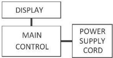
BEFORE PERFORMING ANY ELECTRICAL OR WIRING WORK, TURN OFF THE MAIN POWER TO THE SYSTEM.
flowchart
graph TD
    A["DISPLAY"] --> B["MAIN CONTROL"]
    B --> C["POWER SUPPLY CORD"]
NOTE: The cographs are for explanation purpose only.
Your machine may be slightly different.
- Do not use means to accelerate the defrosting process or to clean, other than those recommended by the manufacturer.
- The appliance shall be stored in a room without continuously operating ignition sources (for example: open flames, an operating gas appliance or an operating electric heater).
• Do not pierce or burn. - Be aware that the refrigerants may not contain an odour.
- Appliance should be installed, operated and stored in a room with a floor area according to the amount of refrigerant to be charged. For specific information on the type of gas and the amount, please refer to the relevant label on the unit itself. When there are differences between the lable and the manual on the Min. room area description, the description on label shall prevail.
• Appliance shall be installed, operated and stored in a room with a floor area larger than 4 m ^2 .
Appliance shall not be installed in an unvertilated space, if that space is smaller than 4 m^2 . - No any open fire or device like switch which may generate spark/arcing shall be around appliance to avoid causing ignition of the flammable refrigerant used. Please follow the instructions carefully when storing or maintaining the appliance to prevent mechanical damage from occurring.

CAUTION:
Risk of fire
flammable materials
Explanation of symbols displayed on the unit
 | CAUTION | This symbol shows that the operation manual should be read carefully. |
 | CAUTION | This symbol shows that a service personnel should be handling this equipment with reference to the installation manual. |
 | CAUTION | This symbol shows that information is available such as the operating manual or installation manual. |
WARNING
- Servicing shall only be performed as recommended by the equipment manufacturer. Maintenance and repair requiring the assistance of other skilled personnel shall be carried out under the supervision of the person competent in the use of flammable refrigerants.
- DO NOT modify the length of the power cord or use an extension cord to power the unit.
- DO NOT share a single outlet with other electrical appliances. Improper power supply can cause fire or electrical shock.
- Please follow the instruction carefully to handle, install, clear, service the appliance to avoid any damage or hazard.
- When maintaining or disposing the appliance, the refrigerant shall be recovered properly, shall not discharge to air directly.
- Compliance with national gas regulations shall be observed.
- Keep ventilation openings clear of obstruction.
- The appliance shall be stored so as to prevent mechanical damage from occurring.
- A warning that the appliance shall be stored in a well-ventilated area where the room size corresponds to the room area as specified for operation.
- Any person who is involved with working on or breaking into a refrigerant circuit should hold a current valid certificate from an industry-accredited assessment authority, which authorises their competence to handle refrigerants safely in accordance with an industry recognised assessment specification. All training shall follow the ANNEX HH requirements of UL 60335-2-40.
Examples for such working procedures are:
• breaking into the refrigerating circuit;
• opening of sealed components;
• opening of ventilated enclosures.
- Transport of equipment containing flammable refrigerants
See transport regulations.
- Marking of equipment using signs
See local regulations.
- Disposal of equipment using flammable refrigerants
See national regulations.
- Storage of equipment/appliances
The storage of equipment should be in accordance with the manufacturer's instructions.
- Storage of packed (unsold) equipment
Storage package protection should be constructed such that mechanical damage to the equipment inside the package will not cause a leak of the refrigerant charge. The maximum number of pieces of equipment permitted to be stored together will be determined by local regulations.
6. Information on servicing
1) Checks to the area
Prior to beginning work on systems containing flammable refrigerants, safety checks are necessary to ensure that the risk of ignition is minimised. For repair to the refrigerating system, the following precautions shall be complied with prior to conducting work on the system.
2) Work procedure
Work shall be undertaken under a controlled procedure so as to minimise the risk of a flammable gas or vapour being present while the work is being performed.
3) General work area
All maintenance staff and others working in the local area shall be instructed on the nature of work being carried out. Work in confined spaces shall be avoided. The area around the workspace shall be sectioned off. Ensure that the conditions within the area have been made safe by control of flammable material.
4) Checking for presence of refrigerant
The area shall be checked with an appropriate refrigerating detector prior to and during work, to ensure the technician is aware of potentially flammable atmospheres. Ensure that the leak detection equipment being used is suitable for use with flammable refrigerants, i.e. non-sparking, adequately sealed or intrinsically safe.
5) Presence of fire extinguisher
If any hot work is to be conducted on the refrigeration equipment or any associated parts, appropriate fire extinguishing equipment shall be available to hand. Have a dry powder or CO_2 fire extinguisher adjacent to the charging area.
6) No ignition sources
No person carrying out work in relation to a refrigerating system which involves exposing any pipe work that contains or has contained flammable refrigerant shall use any sources of ignition in such a manner that it may lead to the risk of fire or explosion. All possible ignition sources, including cigarette smoking, should be kept sufficiently far away from the site of installation, repairing, removing and disposal, during which flammable refrigerant can possibly be released to the surrounding space. Prior to work taking place, the area around the equipment is to be surveyed to make sure that there are no flammable hazards or ignition risks. No Smoking signs shall be displayed.
7) Ventilated area
Ensure that the area is in the open or that it is adequately ventilated before breaking into the system or conducting any hot work. A degree of ventilation shall continue during the period that the work is carried out. The ventilation should safely disperse any released refrigerant and preferably expel it externally into the atmosphere.
8) Checks to the refrigerating equipment
Where electrical components are being changed, they shall be fit for the purpose and to the correct specifications. At all times the manufacturer's maintenance and service guidelines shall be followed. If in doubt consult the manufacturer's technical department for assistance. The following checks shall be applied to installations using flammable refrigerants: the actual refrigerant charge is in accordance with the room size within which the refrigerant containing parts are installed; the ventilation machinery and outlets are operating adequately and are not obstructed; if an indirect refrigerating circuit is being used, the secondary circuit shall be checked for the presence of refrigerant; marking to the equipment continues to be visible and legible.
Markings and signs that are illegible shall be corrected; and refrigerating pipe or components are installed in a position where they are unlikely to be exposed to any substance which may corrode refrigerant containing components, unless the components are constructed of materials which are inherently resistant to being corroded or are suitably protected against being so corroded.
9) Checks to electrical devices
Repair and maintenance to electrical components shall include initial safety checks and component inspection procedures. If a fault exists that could compromise safety, then no electrical supply shall be connected to the circuit until it is satisfactorily dealt with. If the fault cannot be corrected immediately but it is necessary to continue operation, an adequate temporary solution shall be used.
This shall be reported to the owner of the equipment so all parties are advised. Initial safety checks shall include: That capacitors are discharged: this shall be done in a safe manner to avoid possibility of sparking; that there no live electrical components and wiring are exposed while charging, recovering or purging the system; that there is continuity of earth bonding.
7.Sealed electrical components shall be replaced.
1) During repairs to sealed components, all electrical supplies shall be disconnected from the equipment being worked upon prior to any removal of sealed covers, etc. If it is absolutely necessary to have an electrical supply to equipment during servicing, then a permanently operating form of leak detection shall be located at the most critical point to warn of a potentially hazardous situation.
2) Particular attention shall be paid to the following to ensure that by working on electrical components, the casing is not altered in such a way that the level of protection is affected. Check for damage to cables, excessive number of connections, terminals not made to original specification, damage to seals, incorrect fitting of glands, etc. Ensure that apparatus is mounted securely. Ensure that seals or sealing materials have not degraded such that they no longer serve the purpose of preventing the ingress of flammable atmospheres. Replacement parts shall be in accordance with the manufacturer's specifications.
NOTE: The use of silicon sealant may inhibit the effectiveness of some types of leak detection equipment. Intrinsically safe components do not have to be isolated prior to working on them.
8. Intrinsically safe components must be replaced.
Do not apply any permanent inductive or capacitance loads to the circuit without ensuring that this will not exceed the permissible voltage and current permitted for the equipment in use. Intrinsically safe components are the only types that can be worked on while live in the presence of a flammable atmosphere. The test apparatus shall be at the correct rating. Replace components only with parts specified by the manufacturer. Other parts may result in the ignition of refrigerant in the atmosphere from a leak.
9. Cabling
Check that cabling will not be subject to wear, corrosion, excessive pressure, vibration, sharp edges or any other adverse environmental effects. The check shall also take into account the effects of aging or continual vibration from sources such as compressors or fans.
10. Detection of flammable refrigerants
Under no circumstances shall potential sources of ignition be used in the searching for or detection of refrigerant leaks.
A halide torch (or any other detector using a naked flame) shall not be used.
The following leak detection methods are deemed acceptable for systems containing flammable refrigerants. Electronic leak detectors shall be used to detect flammable refrigerants, but the sensitivity may not be adequate, or may need re-calibration. (Detection equipment shall be calibrated in a refrigerant-free area.) Ensure that the detector is not a potential source of ignition and is suitable for the refrigerant used. Leak detection equipment shall be set at a percentage of the LFL of the refrigerant and shall be calibrated to the refrigerant employed and the appropriate percentage of gas (25 % maximum) is confirmed. Leak detection fluids are suitable for use with most refrigerants but the use of detergents containing chlorine shall be avoided as the chlorine may react with the refrigerant and corrode the copper pipe-work. If a leak is suspected, all naked flames shall be removed/ extinguished. If a leakage of refrigerant is found which requires brazing, all of the refrigerant shall be recovered from the system, or isolated (by means of shut off valves) in a part of the system remote from the leak.
Removal of refrigerant shall be according to Removal and evacuation.
11. Removal and evacuation
When breaking into the refrigerant circuit to make repairs—or for any other purpose - conventional procedures shall be used. However, for flammable refrigerants it is important that best practice be followed, since flammability is a consideration. The following procedure shall be adhered to:
-Safely remove refrigerant following local and national regulations;
-Evacuate;
-Purge the circuit with inert gas (optional for A2L);
-Evacuate (optional for A2L);
-continuously flush or purge with inert gas when using flame to open circuit; and -open the circuit.
The refrigerant charge shall be recovered into the correct recovery cylinders if venting is not allowed by local and national codes. For appliances containing flammable refrigerants, the system shall be purged with oxygen-free nitrogen flammable refrigerants. This process might compressed air or oxygen shall not be used for purging refrigerant systems.
For appliances containing flammable refrigerants, refrigerants purging shall be achieved by breaking the vacuum in the system with oxygen-free nitrogen and continuing to fill until the working pressure is achieved, then venting to atmosphere, and finally pulling down to a vacuum (optional for A2L). This process shall be repeated until no refrigerant is within the system (optional for A2L). When the final oxygen-free nitrogen charge is used, the system shall be vented down to atmospheric pressure to enable work to take place. The outlet for the vacuum pump shall not be close to any potential ignition sources, and ventilation shall be available.
12. Charging procedures
In addition to conventional charging procedures, the following requirements shall be followed. Ensure that contamination of different refrigerants does not occur when using charging equipment. Hoses or lines shall be as short as possible to minimise the amount of refrigerant contained in them. Cylinders shall be kept in an appropriate position according to the instructions. Ensure that the refrigeration system is earthed prior to charging the system with refrigerant. Label the system when charging is complete (if not already). Extreme care shall be taken not to overfill the refrigeration system. Prior to recharging the system it shall be pressure tested with OFN. The system shall be leak tested on completion of charging but prior to commissioning. A follow up leak test shall be carried out prior to leaving the site.
13. Decommissioning
Before carrying out this procedure, it is essential that the technician is completely familiar with the equipment and all its detail. It is recommended good practice that all refrigerants are recovered safely. Prior to the task being carried out, an oil and refrigerant sample shall be taken in case analysis is required prior to re-use of reclaimed refrigerant. It is essential that electrical power is available before the task is commenced.
a) Become familiar with the equipment and its operation.
b) Isolate system electrically.
c) Before attempting the procedure ensure that: Mechanical handling equipment is available, if required, for handling refrigerant cylinders; all personal protective equipment is available and being used correctly; the recovery process is supervised at all times by a competent person; recovery equipment and cylinders conform to the appropriate standards.
d) Pump down refrigerant system, if possible.
e) If a vacuum is not possible, make a manifold so that refrigerant can be removed from various parts of the system.
f) Make sure that cylinder is situated on the scales before recovery takes place.
g) Start the recovery machine and operate in accordance with manufacturer's instructions.
h) Do not overfill cylinders. (No more than 80 % volume liquid charge).
i) Do not exceed the maximum working pressure of the cylinder, even temporarily.
j) When the cylinders have been filled correctly and the process completed, make sure that the cylinders and the equipment are removed from site promptly and all isolation valves on the equipment are closed off.
k) Recovered refrigerant shall not be charged into another refrigeration system unless it has been cleaned and checked.
14. Labelling
Equipment shall be labelled stating that it has been de-commissioned and emptied of refrigerant. The label shall be dated and signed. Ensure that there are labels on the equipment stating the equipment contains flammable refrigerant.
15.Recovery
When removing refrigerant from a system, either for servicing or decommissioning, it is recommended good practice that all refrigerants are removed safely. When transferring refrigerant into cylinders, ensure that only appropriate refrigerant recovery cylinders are employed. Ensure that the correct number of cylinders for holding the total system charge is available. All cylinders to be used are designated for the recovered refrigerant and labelled for that refrigerant (i.e. special cylinders for the recovery of refrigerant). Cylinders shall be complete with pressure relief valve and associated shut-off valves in good working order. Empty recovery cylinders are evacuated and, if possible, cooled before recovery occurs. The recovery equipment shall be in good working order with a set of instructions concerning the equipment that is at hand and shall be suitable for the recovery of the flammable refrigerant. If in doubt, the manufacturer should be consulted. In addition, a set of calibrated weighing scales shall be available and in good working order. Hoses shall be complete with leak-free disconnect couplings and in good condition.
The recovered refrigerant shall be processed according to local legislation in the correct recovery cylinder, and the relevant waste transfer note arranged. Do not mix refrigerants in recovery units and especially not in cylinders. If compressors or compressor oils are to be removed, ensure that they have been evacuated to an acceptable level to make certain that flammable refrigerant does not remain within the lubricant. The compressor body shall not be heated by an open flame or other ignition sources to accelerate this process. When oil is drained from a system, it shall be carried out safely.
The power supply cord contains a current measuring device that detects damage to the power cord. Test your power supply cord as follows:
- Plug in the air conditioner.
- The power supply cord will have TWO buttons on the plug head. Press the TEST button. You will notice a click as the RESET button pops out.
- Press the RESET Button. You will notice a click as the button engages.
- The power supply cord is now supplying electricity to the unit. (On some products this is also indicated by a light on the plug head.)
NOTICE:
The power supply cord with this air conditioner contains a current detection device designed to reduce the risk of fire.
In the event that the power supply cord is damaged, it can not be repaired. It must be replaced with a cord from the manufacturer
NOTICE:
- Do not use this device to turn the unit on or off.
• Always make sure the RESET button is pushed in for correct operation. - The power supply cord must be replaced if it fails to reset when either the TEST button is pushed, or it can not be reset. Please contact Customer Service.
PREPARATION
All illustrations in the manual are for explanation purpose only. Your machine may be slightly different. The unit can be controlled by the unit control panel alone or with the remote controller.

DESIGN NOTICE
In order to ensure the optimal performance of our products, the design specifications of the unit and remote control are subject to change without prior notice.
EXHAUST HOSE INSTALLATION
The innovative hose-in-hose design delivers more than 2x faster and stronger cooling. The hoses and adapter must be installed or removed in accordance with the usage mode. For COOL mode & HEAT mode (only for ARC-1230WNH), the adapter and exhausts must be installed. For FAN or DRY mode, the adapter and exhaust hoses can optionally be removed.
Your installation location should meet the following requirements:
- Make sure that you install your unit on an even surface to minimize noise and vibration.
- The unit must be installed near a grounded plug, and the Collection Tray Drain (found on the back of the unit) must be accessible.
- The unit should be located at least 25cm (9.8") from the nearest wall to ensure proper air conditioning. The horizontal louver blade should be at least 50cm (19.7") away from obstacles.
- DO NOT cover the Intakes, Outlets or Remote Signal Receptor of the unit, as this could cause damage to the unit.
| MODE | TEMPERATURE RANGE |
| Cool | 62-95°F | 17-35°C |
| Dry | 62-95°F | 17-35°C |
| Heat (heat pump mode) | 41-86°F | 5-30°C (only for ARC-1230WNH) |
INTRODUCTION
INTRODUCTION TO INVERTER TECHNOLOGY
As pioneers in the air comfort space, we are introducing next generation technology currently used only in high efficiency ductless mini-split air conditioners. The Inverter technology will be featured in our NEX line of portable air conditioners. By utilizing this much more efficient technology, Whynter's Inverter variable-speed system allows the compressor to optimize efficiency and power consumption together, while maintaining a specified output.
This allows for a much quieter operation and significantly reduced energy consumption. The Inverter technology system potentially reduces energy usage by more than 40% while the new hose-in-hose design delivers more than double the cooling output. Below are the advantages of inverter technology:
- At least 40% - 50% cheaper to run as it consumes less power
• Quicker to achieve desired temperature
• Quieter operation
• No temperature fluctuations
• No voltage peaks from compressor
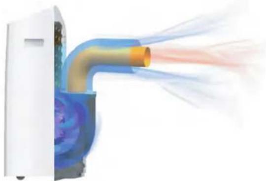
HOSE-IN-HOSE COOLING SETUP
The innovative two-hose in one design and the sealed bottom structure ensure no heat leakage. This cooling setup extracts and exhausts air from the outdoor, so the indoor space reaches an independent and balanced cool air circulation. As a result, the entire room can be cooled down quickly and effectively.
natural_image
Illustration of airflow around a jet engine (no text or symbols)| Model | ARC-1030WN | ARC-1230WN ARC-1230WNH | |
| Operational Modes | Auto / Cool / Fan / Dry | Auto / Cool / Fan / Dry | Auto / Cool / Fan / Dry / Heat |
| Cooling Capacity | 12,000 BTU | SACC 10,000 BTU | 14,000 BTU | SACC 12,000 BTU | 14,000 BTU | SACC 12,000 BTU |
| Heating Capacity | - | - | 12,000 BTU |
| Coverage Area | 500 sq. ft. | 600 sq. ft. | 600 sq. ft. |
| Fan Speed | Continuous | Auto | Low | Medium | High | Continuous | Auto | Low | Medium | High | Continuous | Auto | Low | Medium | High |
| Noise Level | 42.5 / 49.5 / 53.5 | 42.5 / 49.5 / 56.5 | 42.5 / 52.6 / 56.8 |
| Temperature Range | 60-86°F | 60-86°F | Cooling: 60-86°F | Heating: 60-86°F |
| Timer | Up to 24 hours | Up to 24 hours | Up to 24 hours |
| Refrigerant | R32 | R32 | R32 |
| Power Consumption | 1266W | 1293W | 1300W |
| Amps | 11.8 | 11.9 | 11.9 |
| Power Supply | 115V/60Hz | 115V/60Hz | 115V/60Hz |
| CEER | EER | 14.7 | 10.0 | 13.8 | 10.8 | 14.2 | 10.8 |
| Net Weight | 72.8 lbs | 75 lbs | 77.2 lbs |
| Unit Dimensions | 19.5" W x 16.7" D x 32.5" H | 19.5" W x 16.7" D x 32.5" H | 19.5" W x 16.7" D x 32.5" H |
WHAT SHOULD I LOOK FOR WHEN PURCHASING A PORTABLE AIR CONDITIONER?
The right air conditioner helps you cool a room efficiently. An undersized unit won't cool adequately while one that's too large will not remove enough humidity, leaving the air feeling damp. To find the proper air conditioner, determine the square footage of the room you want to cool by multiplying the room length by its width. You also need to know the air conditioner's BTU (British Thermal Unit) rating, which indicates the amount of heat it can remove from a room. Why is the cooling capacity lower on newer models than on older units? A higher number means more cooling power for a larger room. (Be sure you are comparing only newer models to each other- older models may appear to have a higher capacity, but are actually the same). Be sure to "size up" if your portable air conditioner will be placed in a very sunny room, in a kitchen, or in a room with high ceilings. After you've found the right cooling capacity for your room, you can look at other features.
WHY IS THE COOLING CAPACITY LOWER ON NEWER MODELS THAN OLDER MODELS?
Federal regulations require manufacturers to calculate cooling capacity based on a specific test procedure, which was changed just this year. Models manufactured before 2017 were tested under a different procedure and cooling capacity is measured differently than in previous models. So, while the BTUs may be lower, the actual cooling capacity of the air conditioners has not changed.
WHAT IS SACC?
SACC is the representative value of Seasonally Adjusted Cooling Capacity, in Btu/h, as determined in accordance with the DOE test procedure at title 10 Code of Federal Regulations (CFR) 430, subpart B, appendix CC and applicable sampling plans.
ACCESSORIES
| Image | Accessory | Qty |
 | Hose-in-hose (Air intake hose & exhaust hose) | 1 set |
 | Air outlet adapter | 1 piece |
| [60CH] [TKTV] [SD74] C | Exhaust Connector Module A B C* | 1 piece each |
 | Window Slider A | 1 piece |
 | Window Slider B | 1 piece |
 | Window Slider C | 1 piece |
 | Foam Seal A (Adhesive) | 2 pieces |
 | Zip Tie ( For AR C-1230WNH model only) | 2 pieces |
| Image | Accessory | Qty |
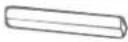 | Foam Seal B (Adhesive) | 2 pieces |
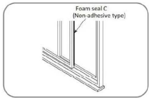
 | Foam Seal C (Non-Adhesive) | 1 pieces |
  | Security Bracket | 1 set |
 | Drain Hose Adaptor (For AR C-1230WNH model only) | 1 piece |
 | Power Cord Buckle (N/A for AR C-1230WNH model) | 1 piece |
 | Bolt | 2 piece |
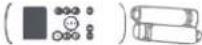 | Remote Control | 1 set |
 | Drain Hose Adaptor | 1 piece |
 | Washable Filter (preinstalled) | 1 piece |
WINDOW KIT INSTALLATION

natural_image
Diagram showing a device before and after transformation, with no visible text or symbolsAdjustable Window Slider Option
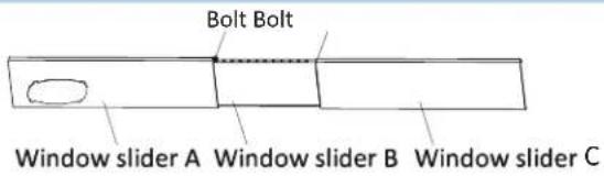
- Measure the window opening where the window kit will be installed.
- Assemble as many sliders as necessary to fit the window. If the window opening is less than the minimum length of a single slider, use the slider that has the hole in it and cut it to the correct length. Make sure not to cut the end that has the hole as this is necessary to attach the exhaust hose adapter.
- Use the window slider bolts to secure the window sliders at the correct length.
Hoses Connector Modules (For Sliding Window)
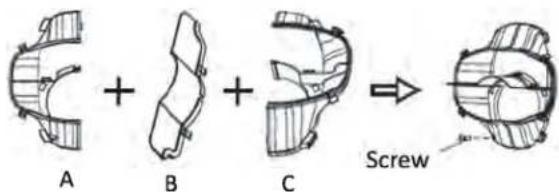
Assemble the exhaust adapter module for sliding windows using the exhaust connector screw as shown. The window slider is eccentric so the exhaust adapter must be installed away from the wall.
Note: For vertical installation, exhaust hose connector module B can be omitted.
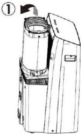
- Rotate the exhaust hose gently backwards.
- Pull out the exhaust hose away from the wall.
Hose-in-hose
NOTE: To ensure proper functioning, DO NOT overextend or bend the hose. Make sure that there is 20" of clearance around the air outlet of the exhaust hose in order for the exhaust system to work properly. All illustrations in this manual are for explanation purposes only. Your air conditioner may be slightly different. The actual shape shall prevail.
NOTE: Once the Exhaust Hose assembly and Adjustable Window Slider are prepared, choose from one of the following two installation methods.
Hung Window or Sliding Window Installation
- Cut adhesive foam seals A and B to the correct lengths and attach them to the window frame as shown.
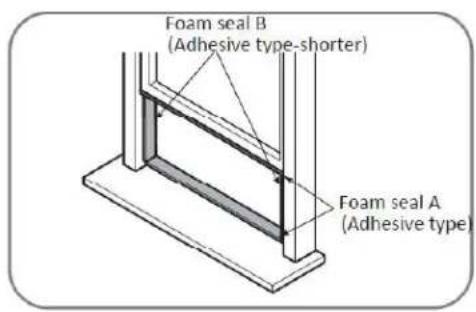
Or
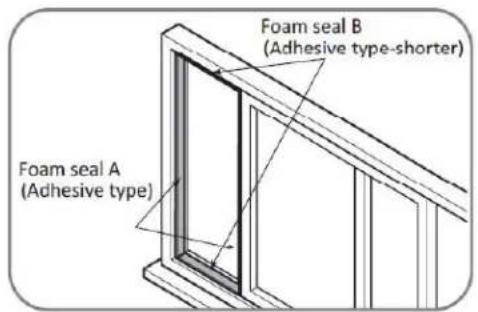
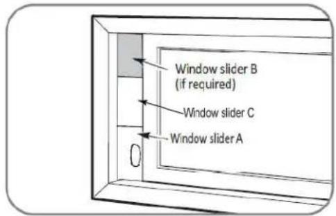
- Insert the window slider kit into the window opening and close the window the secure it in place.

Or
- Cut the non-adhesive foam seal C to match the width or height of the window and insert it between the panes of glass as shown to prevent outside air from entering the window.
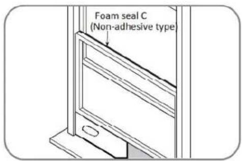
Or
NOTE: Once the Exhaust Hose assembly and Adjustable Window Slider are prepared, choose from one of the following two installation methods.
Hung Window or Sliding Window Installation
- If desired, install the security bracket with 2 screws as shown.

Or

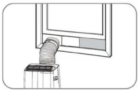
- For a hung window, attach the air outlet adapter onto the exhaust hose and rotate it 90° to secure it in place. For a sliding window, attach the exhaust adapter onto the exhaust hose.

Or

- For a hung window, attach the air outlet adapter onto the window slider kit. For a sliding window, attach the exhaust adapter onto the window slider kit.
natural_image
Line drawing of a window with a coiled hose mounted on a base (no text or symbols)
natural_image
Line drawing of a pipe connection to a window (no text or symbols)CONTROL PANEL

DISPLAY ICONS
Wireless feature (Wireless enabled models only)

Illuminates to show wireless connection is activated.
The timer on/off indicator light
Press and hold on TIMER button for 3 seconds to cancel timing function.
Operation Mode Indicator Lights Auto Cool Dry Fan Heat
Illuminates to show current mode operation.
LED Display 62
Shows the set temperature in °F or °C and the Auto-timer settings. While on FAN modes, it shows the room temperature.
Fan Speed Indicator Lights Cont, Auto Low Med High
Illuminates to show the set fan speed.
Sleep Indicator Light Sleep
Illuminates when Sleep Mode is activated.
Filter Indicator Light
The LED will illuminate after 250 hours of operation. This feature is a reminder to clean the Air Filter for more efficient operation.
CONTROL BUTTONS
Swing / Wireless Mode

Auto-swing
Press to start the auto swing feature. When the operation is ON, press the SWING button to stop the louver at a desired angle.
Turn on Wireless connection mode
To turn on Wireless connection mode on, press and hold the swing button for 3 seconds and the LED display will show "AP" for 3 seconds. Follow the instructions on the Wireless setup manual and the latest app version available for your phone operating system.
Turn off Wireless connection mode
Once the wireless connection mode is successful, press and hold the swing and down buttons for 3 seconds and the LED display will show "OF" for 3 seconds.
Connection Successful
If the connection is successful within 8 minutes, the unit will exit wireless connection mode automatically and the wireless indicator will illuminate.
Connection Failed
If the connection has failed within 8 minutes, the unit will exit Wireless connection mode automatically.
NOTE: When you restart the wireless functions, it will take a period of time to connect to the network automatically. Always be sure your wireless connection is working properly and there is a valid internet connection for Wireless functionality to work.
Timer
Press to program timer delayed switch ON or OFF function.
Modes
Press to change modes. Controls the functions modes: AUTO, COOL, DRY, FAN, and HEAT*.
*only for ARC-1230WNH
CONTROL PANEL

CONTROL BUTTONS
Up and Down buttons

Adjusts set temperature 1^ F | 1^ C increments or timer hours (0 - 24 hours).
NOTE: This unit is capable of displaying set temperature in Fahrenheit or Celsius. To convert from one to another, press and hold the Up and Down buttons for 3 seconds.
Fan
Press to change fan speed. Controls the 5 fan speeds and mode: Continuous, Auto, Low, Medium, and High.
NOTE: In Auto and Dry mode, the fan speed control is disabled Continuous Fan Mode. Press and hold to select continuous fan speed. The fan speed will keep on operating in a continuous speed based on the last fan speed setting.
Sleep Mode
Press to activate Sleep mode. Press SLEEP button again to stop the sleep operation.
NOTE: This feature is not available in FAN or DRY mode.
Filter
Press SLEEP button for 3 seconds to initiate the filter feature.
Power
Press to turn the air conditioner on and off.
ERROR CODES
E1 - Room temperature sensor error
Unplug unit and restart in 5 minutes
E2 - Evaporator sensor error
Unplug unit and restart in 5 minutes
E3 - Condenser sensor error
Unplug unit and restart in 5 minutes
E4 - Display panel sensor error
Unplug unit and restart in 5 minutes
P1 - Water reservoir full
Drain water from the unit
OPERATION INSTRUCTIONS
BEFORE USING YOUR APPLIANCE
- Remove the exterior and interior packing
- Before connecting the appliance to the power source, let it stand upright for approximately 4 hours. This will reduce the possibility of a malfunction in the cooling system from handling during transportation
SWITCHING ON/OFF THE AIR CONDITIONER
The appliance can be switched ON or OFF by pressing the POWER button on the control panel or the ON/OFF button on the remote control
COOLING MODE
In this mode, the air conditioner cools and dehumidifies the room. To activate this function mode, press the MODE button until the COOL indicator light comes on. When the cooling mode is set, the compressor will start in approximately 3 minutes. In cooling mode, hot air is exhausted from the outdoor exhaust port and the exhaust hose must be connected to exhaust out the hot air. The temperature setting range of this air conditioner is from 60°F / 16°C to 86°F / 30°C. To set the temperature, press the + or - buttons. This air conditioner has a 5°F temperature cushion which if the set temperature is within 5°F of the ambient temperature, the unit runs on fan only mode. This saves energy and prolongs the life of the compressor of the air conditioner. To set the fan speed, press the FAN button. In cooling mode, the difference in noise level between the fan speeds is not very noticeable when the compressor is on. Try setting the unit to Fan only mode, you should be able to hear the difference between high and low fan speed settings.
In this mode, the air conditioner only dehumidifies the room, the compressor will activate intermittently depending on the ambient temperature and the fan speed is set to LOW. To activate this function mode, press the MODE button until the DRY indicator light is displayed. Please note that when switching function mode, there will be an approximately 3 minute transition time. In dehumidifying mode, the exhaust hose does not need to be vented. If the exhaust hose is vented, the room will be cooled as it dehumidifies. To prevent cooling, remove the exhaust hose from the window kit and allow the warm air from the rear to be re-circulated into the room. If room temperature is higher than 77°F, the fan speed can be adjusted. If room temperature is lower than 77°F, the fan speed is set at Low.
NOTE: When using dehumidifying mode, venting the exhaust hose to the outside is not required. If vented, the warm air is exhausted to the outside and cooling within the room may occur. Additionally, if the exhaust hose is not vented, the unit may require more frequent draining. Also, the air conditioner does not have a humidistat in which a specific humidity level can be set.
AUTOMATIC MODE
When you set the air conditioner in AUTO mode, it will automatically select cooling or fan only operation depending on what temperature you have selected and the room temperature is close to the unit. The fan speed is automatically selected and cannot be changed. To operate the unit in Auto mode when the unit is on, press the MODE button until the AUTO indicator light comes on.
HEAT MODE (\*only for ARC-1230WNH)
This air conditioner operates on the heat-pump principle, absorbing heat from air outdoors and transferring that heat to the indoor unit. In this mode, the air conditioner heats the room. To activate this function mode, press the MODE button until the HEAT indicator display comes on. When the heating mode is set, the compressor will start in approximately 3-5 minutes. The heating temperature setting range of this air conditioner is from 60^ - 86^ / 16^ - 30^ . To set the temperature, press the UP and DOWN buttons. To set the fan speed, press the FAN button.
FAN ONLY MODE
In this mode, only the fan of the air conditioner runs and circulates the air in the room. To activate this function mode, press the MODE button until the FAN indicator light comes on. In this function mode, the temperature cannot be set. Subsequently, set the desired fan speed by pressing the FAN button. When using FAN only mode, venting the exhaust hose to the outside is optional.
OPERATION INSTRUCTIONS
TIMER (DELAYED SWITCH ON / OFF) FUNCTION
This function mode enables a delayed switch ON or delayed switch OFF of the air conditioner. The time (hours) delay can be set, enabled and disabled.
SETTING SWITCH OFF TIMER
With the air conditioner operating in any function mode, press the TIMER button. The TIMER OFF light will come on. Then set the desired time delay OFF hours by pressing the UP and DOWN buttons. The time increments are at 0.5 hour to up to 10 hours, followed by 1 hour increment up to 24 hours. When the delay time set has elapsed, the air conditioner switches off. To cancel the delayed switch off function, turn off the air conditioner or adjust the time set-ting to 0.0.
SETTING DELAYED SWITCH ON TIMER
With the air conditioner is off, press the TIMER button. The TIMER ON light will come on. Then set the desired time delay ON hours by pressing the UP and DOW N buttons. The time increments are at 0.5 hour to up to 10 hours, followed by 1 hour increment up to 24 hours. When the delay time set has elapsed, the air conditioner switches on. To cancel the delayed switch on function, turn on the air conditioner or adjust the time setting to 0.0.
I SENSE FUNCTION
The remote control serves as a remote thermostat allowing for the precise and comfortable temperature control. With this technology, an efficient temperature sensor is integrated in the remote control. To activate the I SENSE function, press I SENSE button on the remote control. Once this function is activated, the remote control will send the temperature signal to the air conditioner every 3 minutes interval until you press the I SENSE button again. The air conditioner will automatically cancel the I SENSE feature if it does not receive the signal during any 7 minutes interval.
NOTE: The I SENSE feature is not available in DRY and FAN mode. Shifting the operating mode or turning off the unit will cancel the Follow Me feature automatically. The remote control needs to be within 26 feet reach of the indoor unit for the I SENSE mode to work appropriately.
SLEEP MODE
In this mode, the air conditioner gradually increases the set temperature in cooling mode, decreases the noise level and conserves energy. In Economy and cooling mode, the set temperature is increased by 1^ C/2°F in the first 30 minutes. The temperature will then increase by another 1^ C/2°F after an additional 30 minutes. This new temperature will remain the same for 7 hours. To activate this function mode, press the SLEEP button until the SLEEP indicator light comes on.
NOTE: This feature is not available in FAN or DRY mode.
AUTO RESTART
In the event of a power outage, the air conditioner restarts at the previously set function mode and settings when power is restored.
CONTROLLING THE AIR FLOW DIRECTION
The louvers can be controlled to Auto-Swing or in a fixed direction. To control the air flow direction by Auto-Swing, press the SWING button. To set the louvers in a fixed angle or direction, press SWING button while on Auto-Swing mode when desired angle is chosen.
NOISE LEVEL
Portable air conditioners may make sounds that are not familiar to you. The sounds listed below are normal. Noise reflecting off hard surfaces such as a floor or wall can make the sounds seem louder than they actually are.
• The compressor may make a pulsating or high-pitched sound
• Water running from the evaporator to the water tank may make a splashing sound
• Refrigerant flowing may make a gurgling sound
• Fan sound may come from front and back air vents
COMPRESSOR LOCK OUT
This portable air conditioner is optimized to operate in an ambient temperature of 64^ F – 90^ F. The compressor circuit has an automatic 3 minute time delayed start if the unit is turned off and on quickly. This prevents over-heating of the compressor and possible circuit breaker tripping.
REMOTE CONTROL
The portable air conditioner can be switched on by the remote control. To transmit signals from the remote control to the air conditioner, point the front part of the remote handset towards the control panel on the air conditioner. Reception of the signal is confirmed by a beep. The maximum signal transmission distance is approximately 8 meters / 26 feet.
NOTE:
• Other appliances in the same room controlled by a remote control (TV, radio, stereo, etc.), may cause interferences
- Electronic and fluorescent lamps may interfere with the signal transmissions between the remote control and the air conditioner
- Remove the batteries if the remote control is not used for long periods
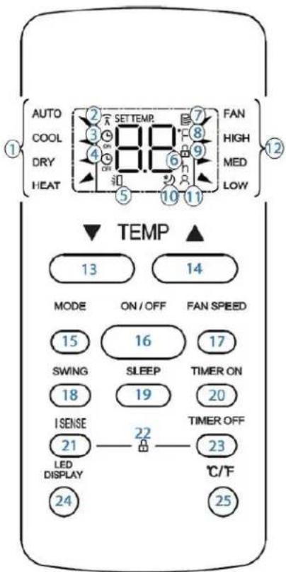
| 1 | Mode indicator | Displays the current selected mode (Auto, Cool, Dry, Heat* or Fan) |
| 2 | Wireless indicator | Displays when the remote is turned on, and disappears when it is turned off |
| 3 | Timer On indicator | Displays when TIMER ON is set |
| 4 | Timer Off indicator | Displays when TIMER OFF is set |
| 5 | Swing indicator | Displays auto-swing feature is turned, and disappears when it is turned off |
| 6 | Temperature/Timer display (h) | Displays the set temperature or timer setting when using ON/ OFF functions "h (hours)" indicator is shown when timer settings are activated |
| 7 | Remote Control indicator | Displays when the remote is turned on and disappears when it is turned off |
| 8 | Temperature Scale indicator | Displays temperature scale Fahrenheit or Celsius |
| 9 | Lock settings indicator | Indicated all the current settings are locked |
| 10 | Sleep Feature indicator | Displays when SLEEP function is activated |
| 11 | I Sense Feature indicator | Displays when I SENSE function is activated |
| 12 | Fan Speed indicator | Displays the current selected fan speed |
| 13 | Up button | Increases set temperature/time |
| 14 | Down button | Decreases set temperature/time |
| 15 | Mode button | Controls the function modes: Auto, Cool, Dry, Heat* and Fan *only for ARC-1230WNH |
| 16 | Power button | Turns the unit On and Off |
| 17 | Fan Speed button | Controls the fan speeds: Auto, High, Medium, or Low (Continuous mode cannot be set using the remote control) |
| 18 | Swing Feature button | Press to stop or start louver auto-swing feature |
| 19 | Sleep Feature button | Starts or stops louver movement and set louver angle |
| 20 | Timer ON button | Enables the Timer On |
| 21 | I Sense Feature button | Press to initiate I SENSE feature |
| 22 | Lock settings button | Press I SENSE and TIMER OFF buttons to lock current settings |
| 23 | Timer OFF button | Enables the Timer Off |
| 24 | LED Display button | Press this button to turn on and turn off the display on the indoor unit |
| 25 | Temperature Scale button | Press to change Temperature Scale (Fahrenheit | Celsius) |
RG51F2(2)/EFU1
REMOTE CONTROL
REPLACING THE REMOTE BATTERIES
This remote control comes with two AAA batteries. Place the batteries in the remote control before use.
- Slide the back cover from the remote downward to expose the battery compartment.
- Insert the batteries, ensure to match the (+) and (-) symbols on the ends of the batteries with the symbols inside the battery compartment.
- Slide the battery cover back into place.
Notes:
- The air conditioner will not respond if curtains, doors or other materials block the signal from the remote control to the unit.
- Prevent any liquid from contact with the remote control. Do not expose the remote control to direct sunlight or heat.
- If the infrared signal receiver on the indoor unit is exposed to direct sunlight, the air conditioner may not function properly. Use curtains to prevent the sunlight from falling on the receiver.
• Do not mix old and new batteries or batteries of different types. - Do not leave the batteries in the remote control if it is not going to be used for more than two months.

natural_image
Illustration of a hand holding two remote control devices with buttons and a close-up of the device (no text or symbols present)CARE AND MAINTENANCE
SAFETY PRECAUTIONS
• Always unplug the unit before cleaning or servicing.
• DO NOT use flammable liquids or chemicals to clean the unit.
• DO NOT wash the unit under running water. Doing so causes electrical danger.
- DO NOT operate the portable air conditioner if the power supply was damaged during cleaning. A damaged power cord must be replaced with a new cord. Contact Whynter Customer Support for more information.
WATER DRAINAGE
When the internal drain pan becomes full the appliance will beep 8 times and the digital display will show error code P1. The air conditioning or dehumidifying action will stop but the fan may continue to operate. Ensure that the appliance is turned off and unplugged and that it is close to a floor drain before setting up any drain option.
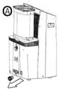
A. Drain Plug
Remove the drain plug and allow the water to completely drain. Replace the bottom drain plug, pressing firmly to ensure a tight fit and no leaks.
B. Continuous Gravity Drain
During dry mode, install continuous drain option so that the appliance will automatically drain collected water. Remove the upper drain plug and attach the drain hose that was provided with the appliance. Place the open end of the drain hose over the receptacle that the appliance will drain into; this could be a basement floor drain, a sink or similar.
Ensure that there are no kinks or bends in the drain hose and that it goes straight down toward the floor. The continuous drain is activated by gravity only. If the hose is not positioned directly downwards, water will not drain correctly.
C. Heat pump drainage (for ARC-1230WNH only)
This unit has a condensate pump feature that can pump out (and up) water through the included drain hose for continuous water removal during HEAT Mode. Remove the heat pump drain plug from the back of the unit and install the drain hose. Place the open end of the hose to a drain area.
NOTE: The condensatepump will only engage during Heat mode and will not work in any other modes. Pump drain hose is required to be installed when using the portable air conditioner in Heat Mode.
NOTE: To reduce pump drain noise, makes sure to attach the drain hose adaptorto the open end of the drain hose. To secure the adaptorin place, use the provided zip tie.
natural_image
Technical line drawing of a mechanical device with labeled components and an arrow indicating motion (no text or symbols present)
natural_image
Line drawing of a portable industrial machine with a handle and control panel (no text or symbols)
natural_image
Line drawing of a mechanical device with a curved handle and labeled point C (no text or symbols on the device itself)
CARE AND MAINTENANCE
UNIT CLEANING
CLEANING
• Unplug the appliance before cleaning or servicing.
- Clean the cabinet with a lukewarm damp cloth and neutral detergent. Dry the cabinet with a lint-free dry cloth.
- Do not use gasoline, paint thinner or other chemicals to clean the appliance.
- Do not wash the appliance directly under a tap or using a hose. It may cause electrical damage.
AIR FILTERS
The air filter should be cleaned every two weeks to ensure efficient performance. In households with animals, the air filters may need to be cleaned more often and the external grills may need to be wiped to prevent blocked air flow.
To access the filter:
- Switch off the air conditioner.
- Hold the exhaust hose, push it backward slightly and then lift it up.
- Remove the filter from the unit.
- Use a vacuum cleaner or tap lightly to remove loose dust and dirt.
- Rinse the filter thoroughly under warm running water (no hotter than 100^ F.)
- Dry thoroughly before re-inserting the filter.
natural_image
Technical line drawing of a mechanical device with no visible text or symbols
LONG-TERM STORAGE
- Drain all water from the appliance.
- Run the appliance on Fan mode for half a day in a warm room to dry the inside of the appliance and prevent mold formation.
- Turn off the appliance and unplug it, wrap the cord and bundle it with tape.
- Remove the batteries from the remote control.
- Clean the air filters and reinstall them.
- Store the appliance in a cool, dark place. Prolonged exposure to direct sunlight or extreme heat can shorten the lifespan of the appliance.
DISPOSAL
This appliance should not be treated as regular household waste. Check for local regulatory compliance regarding the approved and safe disposal of this appliance.
ERROR CODES
P1 - water tray is full - attach drain hose and drain excess water
If any other error code appears on the display, unplug the air conditioner and allow it to sit undisturbed for 5 minutes. If the error code persists when the unit is plugged back in, please contact Whynter Customer Support.
Many common portable air conditioner problems are easily resolved. Try the troubleshooting suggestions below to see if the problems can be resolved before having to contact the service department.
| PROBLEM | POSSIBLE CAUSES | SOLUTIONS |
| The portable air conditioner does not turn on | Power failure / outageThe automatic switch, line fuse, or breaker has been trippedThe power supply voltage is too lowThe power cord is damagedThe L.C.D.I. power plug for the unit is trippedThe internal water reservoir is full and 'P1" appears on display | Restore the power supplyFlip the switch / change the fuse / turn the breaker back on. Also note that you may have too many appliances drawing power on one circuit, you may need to move the other appliances to another circuitMove the unit onto another circuit with the correct voltageCall for service. Only authorized personnel should replace damaged power cord or power plugPress the Reset button on the L.C.D.I. power plugDrain water from the air conditionerPossible loose internal connection.Please contact Whynter for service. |
| The unit turns on but the compressor does not turn on (the fan runs but the unit is not cooling) | The room temperature is outside of the operational tolerances of the unitThe Cooling mode is not onThe compressor has not turned on yet because of its time delayThe set temperature is too highThe internal water reservoir is full and 'P1" appears on display | This unit is designed to work in ambient temperatures of 63°F to 90°F.Press the MODE button until the COOL light is shown on the display.Give the compressor 3 minutes to turn on after the Cooling mode has been selected.Set the air conditioner to a lower temperature.It is recommended to set the temperature to at least 5°F of the ambient temperature.Either manually drain the water by removing the drain plug or allow the unit to exhaust the water itself by running the fan only mode. Then cooling will resume.Possible loose internal connection.Please contact Whynter for service. |
| The air coming out of the unit is not very cold, or the airflow volume is weak | The filters are dirty or obstructedThe air intake or exhaust is obstructedThe unit is set in DRY or FAN modeThe unit is set to low fan speed | Clean the air filtersMake sure there is at least 20" of clearance from the air intake. Make the length of the exhaust hose is as short as possibleSet the unit to the cooling modeSet the unit to a higher fan speed |
Many common portable air conditioner problems are easily resolved. Try the troubleshooting suggestions below to see if the problems can be resolved before having to contact the service department.
| PROBLEM | POSSIBLE CAUSES | SOLUTIONS |
| The unit has worked for a long time, but the room is not cold enough | ·Windows or doors are open·There are too many people in the room·There is direct sunshine into the room·The room is a kitchen or with many heat producing appliances·There is a server in the room·The room is too large | ·Close all windows and doors·You may need additional cooling or another air conditioner.·Close curtains or blinds and try to minimize the amount of direct sunlight into the room.·You may need additional cooling or another air conditioner. |
| The unit is very noisy | ·The unit is not level·The surface underneath the unit is uneven·Low power voltage | ·Make sure the unit is on hard, level and stable surface.·Move the unit to a location with a level and hard floor.·Make sure the wall outlet and support the required power consumption of the air conditioner and do not use an extension cord. |
| The unit leaks water | ·The unit is tilted or not leveled·The water tank is full | ·Make use the unit is leveled·Drain water from the drain plug at the back of the air conditioner |
| Fan speed cannot be changed | ·Fan speed differences are not very noticeable | ·The fan speed difference is not very noticeable when the compressor is on. Try setting the unit to Fan only mode, you should be able to hear the difference between high and low fan speed settings. |
ONE YEAR LIMITED PARTS WARRANTY THREE YEAR WARRANTY ON COMPRESSOR
This WHYNTER product is warranted to the original owner, purchased from an authorized Whynter dealer within the 48 U.S. continental states, for one year from the original purchase date against defects in material and workmanship under normal residential usage. Should your WHYNTER product prove defective within one year from the date of purchase, contact Whynter's Customer Support team with the serial number and proof of purchase to make a warranty claim. A Return Authorization number must be issued before returning any parts or products. Parts or products received without a Whynter issued Return Authorization number will be refused. Under this warranty, Whynter will repair or replace any parts found defective with new or remanufactured parts or exchange the defective product with a new, refurbished, or remanufactured product at our discretion. All defective products and parts covered by this warranty will be repaired or replaced on a mail-in basis to Whynter's Service Center. This warranty is not transferable. After the expiration of the warranty, the cost of labor and parts will be the responsibility of the original owner.
The compressor of portable air conditioner is warranty of an additional two years after the one year limited warranty expires from the date of purchase.
After two months to one year, the customer will be responsible for the return freight cost to Whynter's Service Center. Please package the product carefully in its original packaging to avoid damage in transit. Whynter is not responsible for damage resulting from shipper mishandling or improper packaging. Please retain the original box and packaging materials.
THIS WARRANTY DOES NOT COVER:
- Acts of God, such as fire, flood, hurricanes, earthquakes and tornadoes.
- Improper power supply such as power surge, low voltage, defective household wiring or inadequate fuses.
- Use in commercial or industrial applications.
- Damage, accidental or otherwise, to the product while in the possession of a consumer not caused by a defect in material or workmanship.
- Damage caused by consumer misuse, tampering, lack of maintenance or failure to follow the care and special handling provisions in the instructions.
- Damage to the finish of the case, or other appearance parts caused by wear.
- Damage caused by repairs or alterations to the product by anyone other than authorized by the manufacturer.
- Removal, Replacement Packaging, Freight and Insurance cost for the warranty service.
- Products sold AS IS or from an unauthorized reseller.
- Products that have had their serial numbers removed or defaced.
DISCLAIMER OF IMPLIED WARRANTIES; LIMITATION OF REMEDIES
CUSTOMER'S SOLE AND EXCLUSIVE REMEDY UNDER THIS LIMITED WARRANTY SHALL BE PRODUCT REPAIR OR REPLACEMENT AS PROVIDED HEREIN. CLAIMS BASED ON IMPLIED WARRANTIES, INCLUDING WARRANTIES OF MERCHANTABILITY OR FITNESS FOR A PARTICULAR PURPOSE, ARE LIMITED TO ONE YEAR OR THE SHORTEST PERIOD ALLOWED BY LAW, BUT NOT LESS THAN ONE YEAR. WHYNTER SHALL NOT BE LIABLE FOR CONSEQUENTIAL OR INCIDENTAL DAMAGES SUCH AS PROPERTY DAMAGE AND INCIDENTAL EXPENSES RESULTING FROM ANY BREACH OF THIS WRITTEN LIMITED WARRANTY OR ANY IMPLIED WARRANTY. SOME STATES AND PROVINCES DO NOT ALLOW THE EXCLUSION OR LIMITATION OF INCIDENTAL OR CONSE- QUENTIAL DAMAGES, OR LIMITATIONS ON THE DURATION OF IMPLIED WARRANTIES, SO THESE LIMITATIONS OR EXCLUSIONS MAY NOT APPLY TO YOU. THIS WRITTEN WARRANTY GIVES YOU SPECIFIC LEGAL RIGHTS. YOU MAY ALSO HAVE OTHER RIGHTS THAT VARY FROM STATE TO STATE.
To obtain service or information, contact
Whynter LLC via email at support@whynter.com or call
866-WHYNTER.
Product contents and specifications may change without notice.
Copyright © 2024
WWW.WHYNTER.COM
- Whynter NEX Inverter Dual Hose Portable Air Conditioner with Wireless & LCD Remote
- Supplier's Declaration of Conformity 47 CFR § 2.1077 Compliance Information
- FCC Compliance Statement
- SAFETY PRECAUTIONS
- Read Safety Precautions Before Operation and Installation
- CAUTION
- ELECTRONIC WORK
- WARNING:
- CAUTION:
- WARNING
- Information on servicing
- 7.Sealed electrical components shall be replaced.
- Intrinsically safe components must be replaced.
- Cabling
- Detection of flammable refrigerants
- Removal and evacuation
- Charging procedures
- Decommissioning
- Labelling
- 15.Recovery
- NOTICE:
- PREPARATION
- DESIGN NOTICE
- EXHAUST HOSE INSTALLATION
- INTRODUCTION
- INTRODUCTION TO INVERTER TECHNOLOGY
- HOSE-IN-HOSE COOLING SETUP
- WHAT SHOULD I LOOK FOR WHEN PURCHASING A PORTABLE AIR CONDITIONER?
- WHY IS THE COOLING CAPACITY LOWER ON NEWER MODELS THAN OLDER MODELS?
- WHAT IS SACC?
- ACCESSORIES
- WINDOW KIT INSTALLATION
- Adjustable Window Slider Option
- Hoses Connector Modules (For Sliding Window)
- Hose-in-hose
- Hung Window or Sliding Window Installation
- CONTROL PANEL
- DISPLAY ICONS
- Wireless feature (Wireless enabled models only)
- The timer on/off indicator light
- Operation Mode Indicator Lights Auto Cool Dry Fan Heat
- LED Display 62
- Fan Speed Indicator Lights Cont, Auto Low Med High
- Sleep Indicator Light Sleep
- Filter Indicator Light
- CONTROL BUTTONS
- Swing / Wireless Mode
- Auto-swing
- Turn on Wireless connection mode
- Turn off Wireless connection mode
- Connection Successful
- Connection Failed
- Timer
- Modes
- Up and Down buttons
- Fan
- Sleep Mode
- Filter
- Power
- ERROR CODES
- E1 - Room temperature sensor error
- E2 - Evaporator sensor error
- E3 - Condenser sensor error
- E4 - Display panel sensor error
- P1 - Water reservoir full
- OPERATION INSTRUCTIONS
- BEFORE USING YOUR APPLIANCE
- SWITCHING ON/OFF THE AIR CONDITIONER
- COOLING MODE
- AUTOMATIC MODE
- HEAT MODE (\*only for ARC-1230WNH)
- FAN ONLY MODE
- TIMER (DELAYED SWITCH ON / OFF) FUNCTION
- SETTING SWITCH OFF TIMER
- SETTING DELAYED SWITCH ON TIMER
- I SENSE FUNCTION
- AUTO RESTART
- CONTROLLING THE AIR FLOW DIRECTION
- NOISE LEVEL
- COMPRESSOR LOCK OUT
- REMOTE CONTROL
- NOTE:
- REPLACING THE REMOTE BATTERIES
- Notes:
- CARE AND MAINTENANCE
- WATER DRAINAGE
- Drain Plug
- Continuous Gravity Drain
- Heat pump drainage (for ARC-1230WNH only)
- UNIT CLEANING
- CLEANING
- AIR FILTERS
- LONG-TERM STORAGE
- DISPOSAL
- ONE YEAR LIMITED PARTS WARRANTY THREE YEAR WARRANTY ON COMPRESSOR
- THIS WARRANTY DOES NOT COVER:
Brand : Whynter
Model : ARC-1230WNH
Category : Air conditioner