
LE2104D - Security Camera LG - Free user manual and instructions
Find the device manual for free LE2104D LG in PDF.


| Product Type | Security Camera |
| Brand | LG |
| Model | LE2104D |
| Dimensions (approx.) | 150 x 80 x 80 mm |
| Weight (approx.) | 500 g |
| Power Supply | 12V DC or PoE (Power over Ethernet) |
| Resolution | 2 MP (1920 x 1080) |
| Lens | Fixed 4mm |
| Field of View | 90° |
| Night Vision | IR up to 30 m |
| Video Compression | H.265 / H.264 |
| Connectivity | Ethernet (RJ-45) |
| IP Rating | IP66 (weatherproof) |
| Operating Temperature | -20°C to 50°C |
| Storage | microSD card up to 128 GB |
| Audio | Built-in microphone (two-way audio support) |
| Motion Detection | Yes (configurable) |
| ONVIF Compatibility | Yes |
| Housing Material | Metal |
| Mounting Type | Wall / Ceiling mount |
Frequently Asked Questions - LE2104D LG
User questions about LE2104D LG
0 question about this device. Answer the ones you know or ask your own.
Ask a new question about this device
Download the instructions for your Security Camera in PDF format for free! Find your manual LE2104D - LG and take your electronic device back in hand. On this page are published all the documents necessary for the use of your device. LE2104D by LG.
USER MANUAL LE2104D LG
Before connecting, operating or adjusting this product, please read this owner's manual carefully and completely.
MODEL
LE2104 Series
LE2104D Series

CAUTION
RISK OF ELECTRIC SHOCK DO NOT OPEN

CAUTION: TO REDUCE THE RISK OF ELECTRIC SHOCK DO NOT REMOVE COVER (OR BACK) NO USER-SERVICEABLE PARTS INSIDE REFER SERVICING TO QUALIFIED SERVICE PERSONNEL.

This lightning flash with arrowhead symbol within an equilateral triangle is intended to alert the user to the presence of uninsulated dangerous voltage within the product's enclosure that may be of sufficient magnitude to constitute a risk of electric shock to persons.

The exclamation point within an equilateral triangle is intended to alert the user to the presence of important operating and maintenance (servicing) instructions in the literature accompanying the product.
FCC WARNING: This equipment may generate or use radio frequency energy. Changes or modifications to this equipment may cause harmful interference unless the modifications are expressly approved in the instruction manual. The user could lose the authority to operate this equipment if an unauthorized change or modification is made.
REGULATORY INFORMATION: FCC Part 15
This equipment has been tested and found to comply with the limits for a Class A digital device, pursuant to Part 15 of the FCC Rules. These limits are designed to provide reasonable protection against harmful interference when the equipment is operated in a commercial environment. This equipment generates, uses, and can radiate radio frequency energy and, if not installed and used in accordance with the instruction manual, may cause harmful interference to radio communications.
Operation of this equipment in a residential area is likely to cause harmful interference in which case the user will be required to correct the interference at his own expense.
- A suitable conduit entries, knock-outs or glands shall be provided in the cable entries of this product in the end user.
- Caution: Danger of explosion if battery is incorrectly replaced. Replaced only with the same or equivalent type recommended by the manufacturer. Dispose of used batteries according to the manufacturer's instructions.
- Holes in metal, through which insulated wires pass, shall have smooth well rounded surfaces or shall be provided with brushings.
This Class A digital apparatus complies with Canadian ICES-003.
Warning: Do not install this equipment in a confined space such as a bookcase or similar unit.
Warning: Wiring methods shall be in accordance with the National Electric Code, ANSI/NFPA 70.
Warning: This is a class A product. In a domestic environment this product may cause radio interference in which case the user may be required to take adequate measures.
Warning: To reduce a risk of fire or electric shock, do not expose this product to rain or moisture.
Caution: This installation should be made by a qualified service person and should conform to all local codes.
Caution: To avoid electrical shock, do not open the cabinet. Refer servicing to qualified personnel only.
Caution: The apparatus shall not be exposed to water (dripping or splashing) and no objects filled with liquids, such as vases, shall be placed on the apparatus.
Caution:
This product employs a Laser System. To ensure proper use of this product, please read this owner's manual carefully and retain it for future reference. Should the unit require maintenance, contact an authorized service center. Performing controls, adjustments, or carrying out procedures other than those specified herein may result in hazardous radiation exposure. To prevent direct exposure to laser beam, do not try to open the enclosure. Visible laser radiation when open. DO NOT STARE INTO BEAM.
To disconnect power from mains, pull out the mains cord plug. When installing the product, ensure that the plug is easily accessible.

LG Electronics hereby declares that this/these product(s) is/are in compliance with the essential requirements and other relevant provisions of Directive 2004/108/EC, 2006/95/EC, and 2009/125/EC.
European representative :
LG Electronics Service Europe B.V.
Veluwezoom 15, 1327
AE Almere. The Netherlands
(Tel: +31-(0)36-547-8888)
Disposal of your old appliance

- When this crossed-out wheeled bin symbol is attached to a product it means the product is covered by the European Directive 2002/96/EC.
- All electrical and electronic products should be disposed of separately from the municipal waste stream via designated collection facilities appointed by the government or the local authorities.
- The correct disposal of your old appliance will help prevent potential negative consequences for the environment and human health.
- For more detailed information about disposal of your old appliance, please contact your city office, waste disposal service or the shop where you purchased the product.
EEE Compliance with Directive. (for Turkey only)
Safety way to remove the battery or the battery from the equipment:
Remove the old battery or battery pack, follow the steps in reverse order than the assembly. To prevent contamination of the environment and bring on possible threat to human and animal health, the old battery or the battery put it in the appropriate container at designated collection points. Do not dispose of batteries or battery together with other waste. It is recommended that you use local, free reimbursement systems batteries and accumulators. The battery shall not be exposed to excessive heat such as sunshine, fire or the lile.
Disposal of waste batteries/accumulators

- When this crossed-out wheeled bin symbol is attached to batteries/accumulators of Your product it means they are covered by European Directive 2006/66/EC.
- This symbol may be combined with chemical symbols for mercury(Hg), cadmium(Cd) or lead(Pb) if the battery Contains more that 0.0005% of mercury, 0.002% of cadmium or 0.004% of lead.
- All batteries/accumulators should be disposed separately from the municipal waste stream via designated collection facilities appointed by the government or the local authorities.
- The correct disposal of Your old batteries/accumulators will help to prevent potential negative consequences for the environment, animal and human health.
- For more detailed information about disposal of Your old batteries/accumulators, please contact Your city office, waste disposal service or the shop where You purchased the product.
IMPORTANT SAFETY INSTRUCTIONS
- Read these instructions.
- Keep these instructions.
- Heed all warnings.
- Follow all instructions.
- Do not use this apparatus near water.
- Clean only with dry cloth.
- Do not block any ventilation openings. Install in accordance with the manufacturer's instructions.
- Do not install near any heat sources such as radiators, heat registers, stoves, or other apparatus (including amplifiers) that produce heat.
- Do not defeat the safety purpose of the polarized or grounding-type plug. A polarized plug has two blades with one wider than the other. A grounding type plug has two blades and a third grounding prong. The wide blade or the third prong are provided for your safety. If the provided plug does not fit into your outlet, consult an electrician for replacement of the obsolete outlet.
- Protect the power cord from being walked on or pinched particularly at plugs, convenience receptacles, and the point where they exit from the apparatus.
- Only use attachments/accessories specified by the manufacturer.
- Use only with the cart, stand, tripod, bracket, or table specified by the manufacturer, or sold with the apparatus. When a cart is used, use caution when moving the cart/apparatus combination to avoid injury from tip-over.

natural_image
Symbolic icon of a person pushing a cart inside a circle (no text or symbols)- Unplug this apparatus during lightning storms or when unused for long periods of time.
- Refer all servicing to qualified service personnel. Servicing is required when the apparatus has been damaged in any way, such as power-supply cord or plug is damaged, liquid has been spilled or objects have fallen into the apparatus, the apparatus has been exposed to rain or moisture, does not operate normally, or has been dropped.
The following are warnings and cautions for the safety of the users and for the prevention of any property damage. Please read the following carefully.
WARNING
- Turn off the system before installation. Do not plug in several electric devices to the same outlet.
- This may cause heating, fire, or electric shock.
- Do not place any liquid container on the system, such as water, coffee, or other beverage.
- If liquid is poured onto the system, it can cause a system breakdown or fire.
• Prevent the power cable from being severely bent or having pressure exerted on it by a heavy object.
- This may cause fire.
- Clean the dust around the system on a regular basis. When cleaning the system, always use a dry cloth. Do not use a wet cloth or other organic solvents.
- This may damage the surface of the system and can cause a system breakdown or electric shock.
- Avoid any place with moisture, dust, or soot.
- This can cause fire or electric shock.
- When pulling the power cable from the plug, do so gently. Do not touch the plug with wet hands and avoid using the plug if the holes in the outlet are too loose.
- This may cause fire or electric shock.
- Do not attempt to disassemble, repair, or modify the system on your own. It is extremely dangerous due to the high voltage running through the system.
- This may cause fire, electric shock, or serious injury.
- Check for any danger signs such as a moist floor, a loosened or damaged power cable, or an unstable surface. If you encounter any problems, ask your dealer for assistance.
- This may cause fire or electric shock.
- Keep a distance of at least 15 cm between the back of the system and the wall for the cables connected to the system otherwise, they may be bent, damaged, or cut.
- This may cause fire, electric shock, or injury.
- Install the system in a cool place without direct sunlight and always maintain room temperature. Avoid candlelight and heat generating devices such as heaters. Keep the system away from places where many people pass.
- This may cause fire.
• Install the system on a plain surface with sufficient air ventilation. Do not place the system on an elevated surface.
- This may cause system breakdown or serious injury.
- The power outlet must be placed on the ground, and the voltage range must be within 10 % of the voltage rate. Do not use the same outlet with a hair dryer, iron, refrigerator, or any heating appliances.
- This may cause fire, over heating or electric shock.
- When the system's battery is depleted, replace it with the same or equivalent type of battery specified by the manufacturer. Depleted batteries should be discarded according to the manufacturer's instructions.
- This may cause an explosion.
- If the system's HDD exceeds its life span, you may not be able to recover any data stored inside the HDD. If the video on the system screen appears 'damaged' while playing a recording stored inside the system's HDD, it must be replaced with a new one. Ask for an engineer's assistance for HDD replacement from your dealer.
- LG Electronics is not responsible for deleted data caused by user mishandling.
CAUTION
Please beware of the following precautions before installing the DVR.
- Avoid positioning the product in any place where the unit may come into contact with moisture, dust, or soot.
- Avoid placing in direct sunlight or near heating appliances.
- Keep the product away from electric sparks or magnetic substances.
- Avoid temperature extremes (recommended operating temperature is between 0^ - 40^ ).
- Do not place any conductive material through the ventilation grills.
- Keep the system turned off before installation.
- Ensure enough space is left for cable connections.
- Place the system on a solid surface with sufficient air ventilation. Avoid any surface that vibrates.
- Placing the system near electronic devices such as a radio or a TV may cause the product to breakdown.
- Do not disassemble the product without seeking assistance from LG Electronics.
- Do not place any heavy object on the system.
• Prevent any substances from being inserted into the system.
- This may cause system breakdown.
• Install the system in a place with sufficient air ventilation.
- Keep at least 15 cm distance between the back of the system and the wall, and at least 5cm distance between the side of the system and the wall.
- Do not install the system in a place with high magnetic, electric wave, or wireless devices such as a radio or a TV.
- Do not install the system in a place with magnetic objects, electric frequencies, or vibration.
- Do not place any heavy object on the system.
- This may cause system breakdown.
• Install the system on a stable, level surface.
- The system may not operate properly.
• Install the system in a place with appropriate moisture and temperature levels.
- Avoid installing the system in a place with high (over 40 °C) or low (under 0 °C) temperature.
- The system can be damaged from a strong impact or vibration. Avoid throwing objects within the vicinity of the system.
- Avoid direct sunlight or any heating appliances.
- Recommended operating temperature is over 0 °C (32 °F).
- Ventilate the air inside the system operation room, and tighten the system cover firmly.
- System breakdown may be caused by an inappropriate environment.
It is recommended to use AVR (Automatic Voltage Regulator) for a stable power supply.
It is recommended to coil the core-ferrite around the connector of the system to avoid electromagnetic interference.
• The outlet must be placed on the ground.
• If there is strange sound or smell, unplug the power cable immediately and contact the service center.
- This may cause fire or electric shock.
• In order to maintain stable system performance, have your system checked regularly by the service center.
- LG Electronics is not held responsible for system breakdown caused by user mishandling.
- There is a risk of explosion if a battery is replaced by an incorrect type. Dispose of used batteries according to the instructions.
- Do not overturn the product during use.
Contents
Introduction 7
Features 7
Accessories 7
Front Panel 8
Rear Panel 9
Remote Control 10
Connections and settings 11
Precautions 11
Basic Connection Overview ......11
Connecting Camera 12
Connecting Display device....12
Connecting Audio device ....12
Connecting USB device 12
Connecting CONSOLE (RS-232C) Port 13
Mouse 13
Connecting Network 13
Connecting RS-485 Device 13
Connecting Alarm Input and Alarm Output ....14
HDD INSTALLATION ....15
Installing or Replacing the Hard Disk Drive ....15
System Operation 17
General Explanation of the Live Screen on the Main Monitor ....18
Configuration menu ......22
Camera settings....23
Schedule settings 26
Display settings 29
Event Settings 30
Network Settings 31
System Settings 35
Recording 40
Instant recording ....40
Search and Playback 41
Playback ....41
Search 41
LG Network Client Program 44
Introduction 44
Getting Started 44
Operation and settings 47
Using the Export function ....57
Additional Programs 58
Emergency Agent Program 58
Export Viewer Program ....59
Web Viewer Program 60
Reference 61
Troubleshooting 61
Recommended Devices 63
Time zones 65
Factory Default Configuration Settings ....66
Recording Time Table (250GB HDD)....69
Specifications 72
Introduction
Features
• Stable embedded Linux operating system.
• Journal filing system for HDD file recovery following power recovery.
• Small file sizes with H.264 compression.
- Internal storage expandable to 1 TB. (Expandable if new high capacity HDD is launched)
• NTSC and PAL selectable video format.
• Full real-time recording.
| NTSC | Up to 120 IPS @ 352 x 240, Up to 60 IPS @ 704 x 240, Up to 30 IPS @ 704 x 480 |
| PAL | Up to 100 IPS @ 352 x288, Up to 50 IPS @ 704 x 288, Up to 25 IPS @ 704 x 576 |
• Various recording resolutions and quality levels.
- D1(704 x 480), Half D1(704 x 240), CIF(352 x 240) : NTSC
- D1(704 x 576), Half D1(704 x 288), CIF(352 x 288): PAL.
-
5 step quality level (Highest, High, Standard, Low, Lowest).
-
Easy operation using various user interface & user friendly GUI.
- Optical mouse, Full function IR remote controller
• Powerful multiplex function. - Simultaneous live display, recording, playback, network transmission, back-up.
- Various search function.
- Date/time search (calendar search), event search, bookmark search.
• Event data protection by event partition recording.
• Pre-alarm recording (Up to 1 minute).
• Motion event recording. - Recording image rate & quality adjustment per individual camera.
• Powerful record scheduling.
• Instant playback in surveillance mode.
• Perfect audio/video synchronization.
• Automatic backup by schedule.
• Image authentication (Watermark).
• Three USB 2.0 ports for backup interface. - Setup configuration export/import with USB memory stick.
- Easy system S/W update with USB memory stick or network.
- Clients S/W can manage maximum 100 DVR servers.
• Max five clients can access one DVR server simultaneously.
• Network bandwidth throttle.
- Automatically adjust a bandwidth according to network speed status of unit.
• Remote alarm notification via client software or E-mail.
• Time and date sync from NTP server.
• Daylight saving mode.
• Covert camera protection.
• Back-up CD auto run.
• User management (User level control).
- PTZ Control.
- For more details see page 64.
- Dome camera telemetry control (Dome OSD control).
Accessories
| Software Install CD | 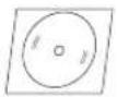 |
| Mouse (PS2 type) | 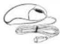 |
| Remote Control | 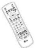 |
| AAA type batteries |  |
| Power Plug | 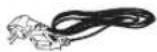 |
| DC adaptor | 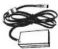 |
| SATA cable(s) | 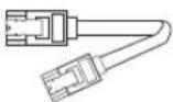 |
| SATA power cable | 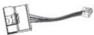 |
| HDD fixing screws |  |
Front Panel
LE2104D model
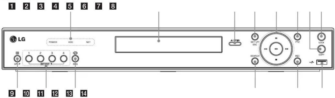
LE2104 model
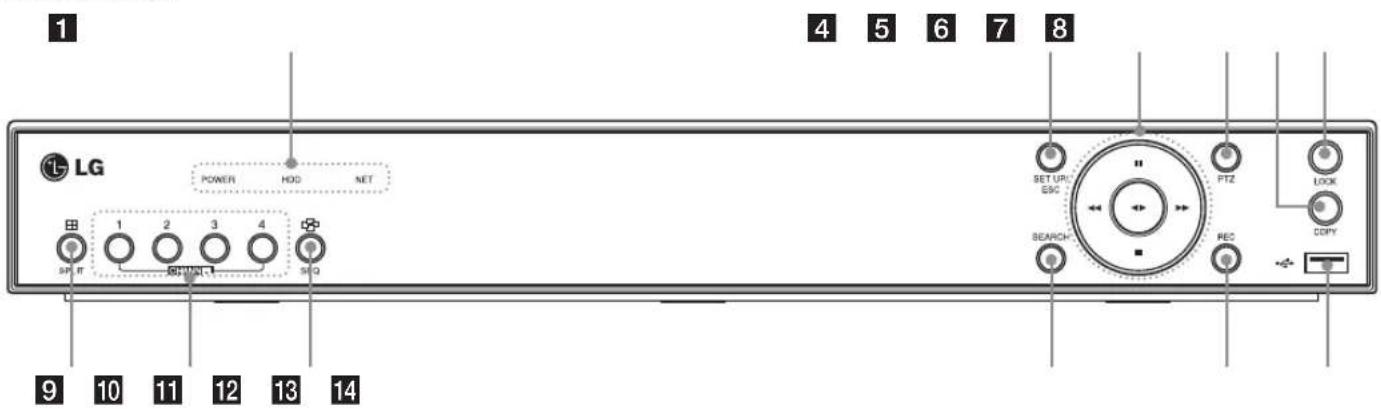
1 POWER Indicator: Lights when the DVR is powered.
HDD Indicator: Blinks when the HDD is accessed.
NET Indicator: Lights when a network cable is connected.
2 Disc Tray (LE2104D model only): Insert a disc here.
3 OPEN (LE2104D model only): Opens or closes the disc tray.
4 SETUP/ESC: Displays the setup menu or cancels operation on the setup menus.
5 Playback Control Buttons
- II: Pauses playback.
- ←: Search the recorded images in reverse.
- ◀▶: Playback or reverse playback of recorded images.
- ▶▶: Forward search the recorded images.
- ■: Stops playback.
6 PTZ: Switches this unit to PTZ mode to control the PTZ camera connected.
7 COPY: Copies the recording data to an external device.
8 LOCK: Displays the lock menu to change the user type or disable the system operation.
9 SPLIT: Press to see different multi screen modes.
10 CHANNEL: Selects the respective camera.
11 SEQ: View all channels in sequence.
12 SEARCH: Displays the search menu.
13 REC: Starts or stops instant recording.
14 USB Port: Connect an external USB device for backup or playback. (The USB type mouse is not supported.)
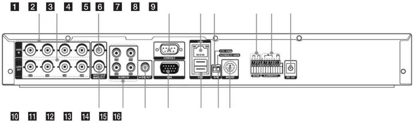
Rear Panel
Rear panel with the TV or VGA output select switch.
Rear panel without the TV or VGA output select switch.
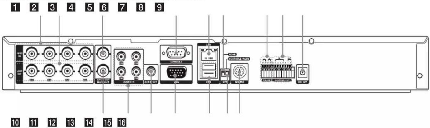
1 VIDEO INPUT Connect the camera's video output to these BNC connectors.
2 LOOP OUT The signal from VIDEO INPUT connector is looped out to this connector.
3 SPOT-OUT (BNC Type Connector) Connect to spot monitor or display device.
4 CONSOLE (RS-232C Connector) Used to connect to a host device equipped with RS-232C connector (such as a personal computer). This unit can be controlled from other devices via this connector.
5 LAN Port Connect the ethernet 10/100 Mbps network cable for controlling this unit via a PC network.
6 TV or VGA output select switch. (This switch is optional by models.)
7 RS-485 Terminals Connect RS-485 compatible cameras. Connect the LKD1000 controller to D2 terminal.
8 ALARM IN/OUT Terminals - IN: Input terminals for alarm(relay) signal. - OUT: Output terminals for alarm(relay) signal.
9 Power Cord Inlet (DC 12 V) Connect the power plug.
10 MAIN-OUT (BNC Type Connector) Connect to main monitor or display device.
11 AUDIO INPUT Connect the audio output of an external device.
12 AUDIO OUT Connect the audio input signal of an external device.
13 VGA Connect a VGA monitor.
14 USB Ports Connect an optional extension USB device.
15 CONSOLE or ATM output select switch. (ATM is a reserved function.)
16 MOUSE Connect an mouse device (PS2 Type).
Remote Control
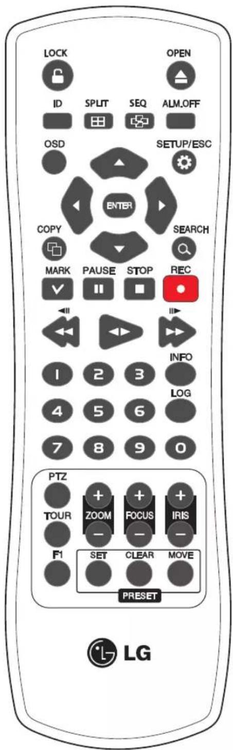
- LOCK: Displays the lock menu to change user type or disable system operation.
- OPEN: Opens or closes the disc tray. This button is only used for LE2104D models.
- ID: Set the appropriate DVR system ID to operate via the IR Remote Controller when using the multiple DVR. Press the ID button then press the number button within 2 seconds to select the system ID of the DVR. If you set the system ID to "0", you can control multiple DVR at the same time.
• SPLIT: Press to see different multiscreen modes.
- SEQ: Views the all channels in sequence on the full screen display mode. You cannot use sequence mode with the 4 split.
- ALM.OFF: Cancels alarm activation and returns the system to the condition before the alarm was activated.
• OSD: Displays the submenu.
- SETUP/ESC: Displays the setup menu or cancels operation of the setup menu.
- Arrow Buttons (◀ ▶ ▲ ▼): Selects or moves between the menu options.
• ENTER: Confirms menu selections.
• COPY: Copies the recording data to an external device.
• SEARCH: Displays the search menu.
- MARK: Sets the mark point for recording search. You can set the mark point during the single or multi channel playback of recorded data.
• PAUSE (II): Pauses playback.
• STOP(■): Stops playback.
• REC (●): Starts or stops recording.
◀◀/◀◀: Searches the recorded images in reverse or skips the recorded images.
◀ / ▶: Playback or reverse playback of recorded images.
▶▶ / ▶▶ : Forward searches the recorded images or skips the recorded images.
• Number Buttons (0,1-9): To select the PTZ preset number, ID, or channel.
• INFO: Displays the system information window.
• LOG: Displays the System Log List window.
- PTZ: Switches this unit to PTZ mode to control the connected PTZ camera.
• TOUR: Tours all registered preset positions in the camera.
• ZOOM + / -: Zooms in/out on the playback window.
• FOCUS + / -: Adjusts the focus of a camera.
• IRIS + / -: Adjusts the iris of a camera.
• F1: This button is not available.
- PRESET
- SET: Registers the PTZ camera's preset positions.
- CLEAR: Deletes a memorized preset position.
- MOVE: Moves the camera to the preset position.
Connections and settings
Precautions
- Depending on the camera and other equipment there are various ways to connect the unit. Please refer to the camera manual or manuals for other devices as necessary for additional connection information.
- Be sure to switch off the camera before installation and connection.
Basic Connection Overview
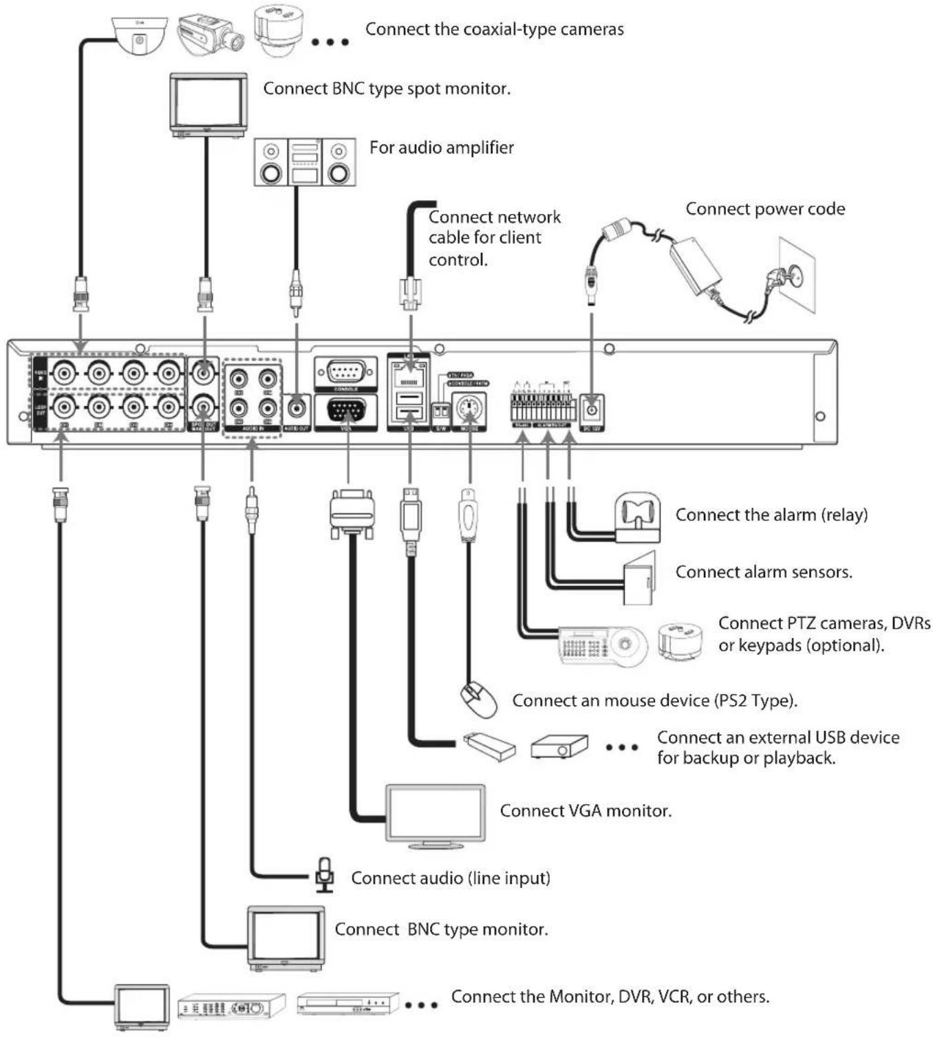
flowchart
graph TD
    A["Camera"] --> B["Coaxial-type cameras"]
    C["Monitor"] --> D["BNC type spot monitor"]
    E["Analog unit"] --> F["For audio amplifier"]
    G["External Monitor"] --> H["Connect the monitor, DVR, VCR, or others."]
    I["Computer"] --> J["Connect audio (line input)"]
    K["Analog unit"] --> L["Connect VGA monitor"]
    M["Analog unit"] --> N["Connect an external USB device for backup or playback."]
    O["Analog unit"] --> P["Connect an mouse device (PS2 Type)."]
    Q["Analog unit"] --> R["Connect alarm sensors."]
    S["Analog unit"] --> T["Connect power code"]
    U["Analog unit"] --> V["Connect network cable for client control."]
    W["Analog unit"] --> X["Connect the alarm (relay)."]
Connecting Camera
Connect cameras to the unit using 75 Ω video coaxial cables with BNC connectors. There are two BNC connectors for each camera. Either connector can receive a camera's signal. This signal is looped-through (directly connected) to the other connector, so that you can send the camera's signal to other equipment.
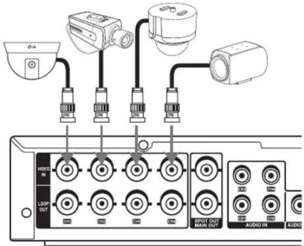
Connecting Display device
Make one of the following connections, depending on the capabilities of your existing equipment.
The LE2104/LE2104D models without TV/VGA output select switch can be outputted simultaneously from the VGA and MAIN OUT jack. On other LE2104/LE2104D models with TV/VGA output select switch, main monitor type should be selected to display the main screen.
CCTV(Composite Video Type) Monitor connection
When using the analog TV monitor, set the Video Output mode select switch to TV position.
Connect the unit to the monitors via 75 Ω video coaxial cables with BNC connectors.
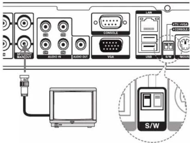
VGA Monitor connection
When using the VGA monitor, set the Video Output mode select switch to VGA position.
Connect the VGA jacks on the rear of the unit to the corresponding input jacks on the TV or monitor using the VGA cable.
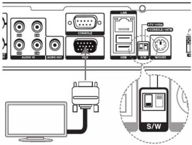
Connecting Audio device
Connect the AUDIO OUT jacks on the unit to the mono audio in jacks on your audio device.
Connecting USB device
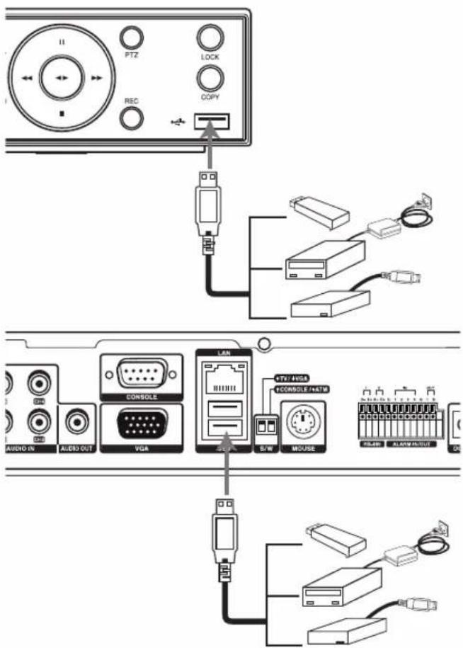
USB memory device
Insert the memory device into the USB port. The system automatically recognizes the device.
Using a USB memory device the system software can be easily upgraded.
USB backup device
Connect the USB cable of the USB backup device to the USB port.
(Example: HDD or other external storage.)
Note:
Do not connect USB type mouse.
Connecting CONSOLE (RS-232C) Port
The serial RS232 console port connector is used to connect a PC to the unit for service purposes. Use a null-modem cable to connect the serial port of the PC to the unit. This terminal is compliant with the RS-232C standard.
Mouse
Connect the mouse for function control of the unit.
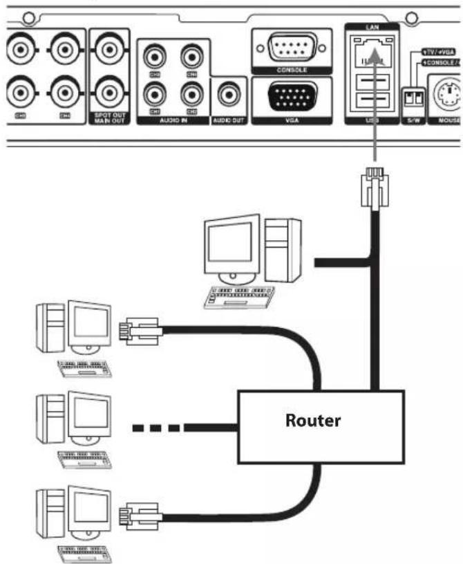
Connecting Network
You can control and monitor the system via network. With the remote control (monitoring), you can change the system configuration or monitors the image via network (LAN). After the installation, the network on the system setup menu should be set to make the remote control and monitoring work.
flowchart
graph TD
    A["Computer Port 1"] --> B["Router"]
    C["Computer Port 2"] --> B
    D["Computer Port 3"] --> B
    E["Computer Port 4"] --> B
    F["Computer Port 5"] --> B
    G["Computer Port 6"] --> B
    H["Computer Port 7"] --> B
    I["Computer Port 8"] --> B
    J["AUDIO IN"] --> K["AUDIO OUT"]
    L["AUDIO IN"] --> M["AUDIO OUT"]
    N["AUDIO OUT"] --> O["AUDIO OUT"]
    P["VGA"] --> Q["VGA"]
    R["LAN"] --> S["LAN"]
    T["USB"] --> U["USB"]
    V["S/W"] --> W["S/W"]
    X["TV/VSA"] --> Y["TV/VSA"]
    Z["CONSOLE"] --> AA["CONSOLE"]
    AB["MOUSE"] --> AC["MOUSE"]
LAN connection
Connect the LAN port to an available 10/100 base-T port with a straight ethernet cable (not supplied). The NET indicator on the front panel will be lit.
Automatic network configuration
The DVR can automatically obtain and configure the network interface via DHCP.
Manually configure network
The DVR may be manually configured by assigning an IP address, subnet mask, gateway and DNS.
Connecting RS-485 Device
This DVR has two data terminals. Use this port to connect PTZ cameras, DVRs or keypads (optional).
| RS-485 Terminal Description | |
| D - (DATA -) Data Transmission/Reception | |
| D + (DATA +) Data Transmission/Reception | |
| GND Shield |
Connecting the PTZ camera
Connecting the PTZ serial communication lines to the RS-485 terminal.
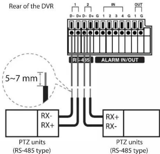
Notes:
- When connecting lines, connect the D - of the DVR to RX - of the PTZ unit and D + of the DVR to RX + of the PTZ unit correctly.
- Recommended initial data are 9600 Baud Rate, 8 Data bits, 1 Stop bit and No parity.
- When connecting PTZ cameras to DVRs it is necessary to set the setup menu for this unit according to the RS-485 settings of the camera and DVRs.
Connecting LKD1000 controller
Connecting the LKD1000 controller to control the DVR. (Refer to the manuals of the LKD1000 controller for more details.).
Rear of the DVR
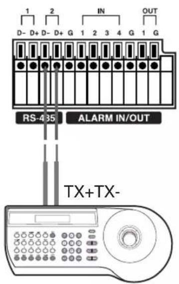
LKD1000 Controller
Notes:
- Do not connect a PTZ camera with LKD1000 controller to the D1 or D2 port. It may cause a malfunction.
- The MAIN and SPOT buttons of the LKD1000 controller are not activated for LE2104/LE2104D models.
Connecting Alarm Input and Alarm Output
Alarm terminals are used to connect the alarm devices such as sensors, door switches, etc.
Alarm Input
You can connect up to 4 alarm sensors.
Each alarm sensor should be connected with G (GND). The signal state is adjustable to N/O (Normal Open) or N/C (Normal Close) through the setup menu.
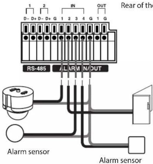
| Terminal No. Description | |
| 1 Alarm Input 1 | |
| 2 Alarm Input 2 | |
| 3 Alarm Input 3 | |
| 4 Alarm Input 4 | |
| G Ground | |
Alarm Output
Connect the alarm device to the alarm output. Alarm signal output at an event occurrence.
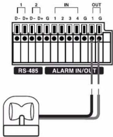
Rear of the DVR
| Terminal No. Description | |
| 1 Alarm Output 1 | |
| G Ground | |
Note:
The internal switching relays are rated for 0.3 A at 125 V AC or 1 A at 30 V DC. If the electric current is higher than that the unit can be damaged.
HDD INSTALLATION
Note for Hard Disk Drive
The internal hard disk drive (HDD) is a fragile piece of equipment. Please follow the guidelines below when using the DVR to protect against possible HDD failure.
We recommend that you back up your important recordings onto an external backup device in order to prevent accidental loss.
Make sure that the power is turned OFF when attaching or removing the HDD.
- Do not move the DVR while the power is on. - Do not use the DVR in excessively hot or humid places, or in places that may be subject to sudden changes in temperature. Sudden changes in temperature can cause condensation to form inside the DVR. This can be a cause of HDD failure.
- While the DVR is switched on, do not unplug from the wall socket or switch the electricity off from the breaker switch.
- If there's a power failure while the DVR is on there is a chance that some data on the HDD will be lost.
- Do not drop the HDD. Also do not put the metallic object such as coins or screwdrivers into the HDD tray.
- When a power failure occurs during recording, avoid adding, replacing or transporting the HDD as the recorded data may be erased. In this case, turn the power back on to boot up the unit normally with the HDD that was being used at the time of the power failure attached. Then add, replace, or transport the HDD.
- The HDD is very delicate. Handle the HDD with care and follow the precautions below because even a small shock may damage the internal components of the HDD.
- Do not place the HDD on a desk or a table directly. Put a thick cushion under the HDD because even a small shock may damage the internal components of the HDD.
- Do not use an electric screwdriver. Vibrations and shocks caused by an electric screwdriver may damage the internal components of the HDD.
- When replacing the HDD, do not knock the HDD with other components such as another HDD and the HDD tray.
- Do not knock the HDD with tools such as a driver when replacing the HDD.
- Protect the hard disk drives from static electricity.
Installing or Replacing the Hard Disk Drive
Installing the Hard Disk Drive
You can install up to 2 HDDs. (LE2104 model only)
However, since the product contains many parts which may incur electric shocks, accidents or product breakdown, and because improper installation or setup may disturb HDD recognition or normal product operation, you should consult with an expert from the store where the product was purchased.
Turn the power of the unit off and detach the power plug from the outlet.
- Remove the fixing screws on the left/right side and rear panel.
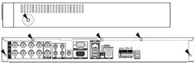
natural_image
Back view of a computer rack with ports, connectors, and memory unit (no text or symbols visible)-
Detach the top case by sliding it after removing the screws.
-
Detach the front panel.
-
Remove the screws and detach the hard disk mounting brackets from the unit.
• In case of LE2104 model
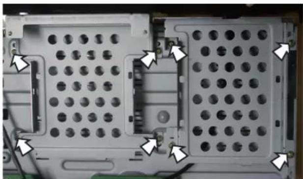
natural_image
Close-up of a computer motherboard showing two grid-like compartments with white arrows pointing to specific components (no text or symbols visible)• In case of LE2104D model
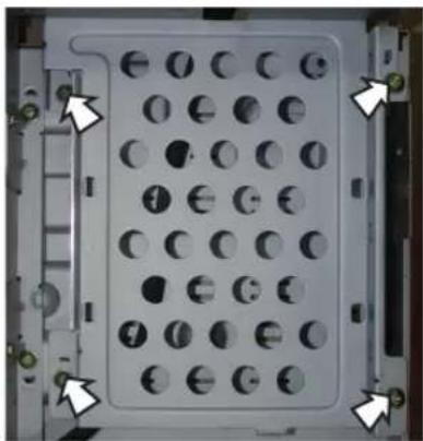
natural_image
Close-up of a mechanical component with circular holes and mounting brackets (no visible text or symbols)- Attach the HDD onto the hard disk mounting brackets with four screws.
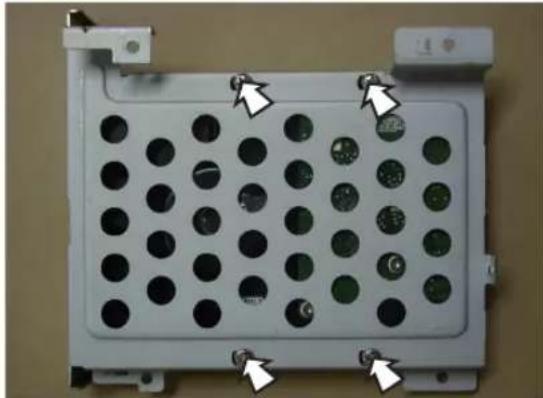
natural_image
Close-up of a white electronic device panel with circular holes and mounting bracket (no visible text or symbols)-
Attach the hard disk mounting brackets with the screws.
-
Connect the HDD power cable. You must use the supplied SATA power cable. The SATA power cable that used for normal PC is not compatible with this unit.
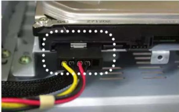
natural_image
Close-up of electronic components with colored wires and connectors, no visible text or symbols- Connect the Serial SATA cable.
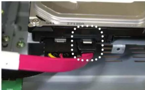
natural_image
Close-up of a red-handled glove inserting into an electronic device component (no visible text or symbols)- Connect the SATA cable to the SATA connector on the main board.
- When installing 1 HDD.
Connect the SATA cable of the HDD to the SATA connector of the main board.
- When installing 2 HDDs.
9-1. Connect the SATA cable of the first HDD to the first SATA connector of the main board.
9-2. Connect the SATA cable of the second HDD to the second SATA connector of the main board.
-
Assemble the front panel and top case.
-
Fix the screws.
-
After installing the HDD, you must format the HDD using the setup menu (See page 37).
Note:
When you add the new HDD, do not change the position of the HDD. It may delete the current data and cause a malfunction.
Replacing the Hard Disk Drive
Turn the power of the unit off and detach the power plug from the outlet.
-
Follow steps 1-4 described in "Installing the Hard Disk Drive".
-
Remove the connector from the HDD.
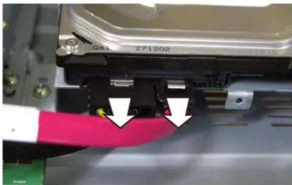
natural_image
Close-up of a mechanical component with red and white arrows pointing to a yellow connector (no visible text or symbols)- Remove the screws from the hard disk drive on the bottom of the hard disk mounting bracket.
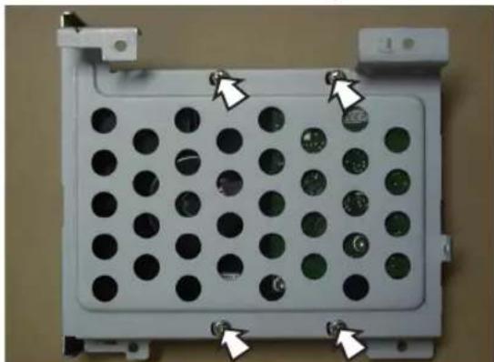
natural_image
Close-up of a white electronic device panel with circular holes and three metallic pins, no visible text or symbols.-
Remove the HDD from the hard disk mounting bracket.
-
Install the new HDD in the reverse order to when replacing the hard disk drive.
-
After replacing the hard disk drive, insert the power plug into the outlet and turn the power of the unit on.
Notes:
• Make sure that each of the SATA cables is connected to the connector housing through its holes.
• Do not stack them nor keep them upright.
• Do not use an electric screwdriver to fix them.
The HDD should be formatted after installation
When installing or adding the HDD, it should be formatted before use. You can set the event or normal partition space of the HDD. (See page 37). The HDD which has been used in another device should be formatted to make sure normal storage.
Recommended HDD
The following HDD has been tested and compatibility is ensured. When you attach multiple HDDs use the recommended HDDs.
Note:
If you do not use the recommended HDD, the system may not be operated normally.
| Maker RPM Capacity Interface Model No. | |||
| Seagate | 7,200 250 GB SATA ST3250311SV | ||
| 7,200 500 GB SATA ST3500410SV | |||
| 5,400 1 TB SATA ST31000424CS | |||
| Hitachi 5 | 700 1 TB SATA HCS5C1010CLA382 | ||
System Operation
-
Turn on the unit. System booting will commence. The LG logo image will be displayed on the main monitor during the system booting.
-
When the booting is complete, the login window will be displayed. Select a user name by using the mouse or arrow, then the ENTER button on the remote control or front panel.
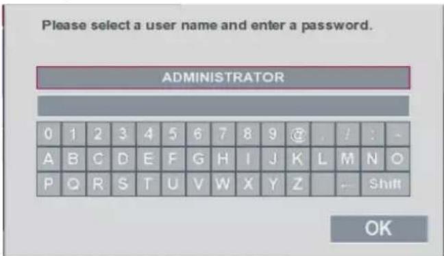
- ADMINISTRATOR: Unlimited operation of the unit.
- Power User: Use of the limited functions of the system. (The setup configuration is not allowed to change.)
- Normal User: Use of the limited functions of the system. (Multiscreen monitor and live image view are available.)
-
Enter the password by using the virtual keyboard. (Initial password is "000000".)
-
Select [OK] button and press ENTER. You can see the live screen and operate the system.
Notes:
- The LE2104/LE2104D series models with TV/VGA output select switch can not be outputted simultaneously from the VGA and MAIN OUT jack. Consequently, the user is obliged to choose either the composite monitor or the VGA monitor. When set to composite monitor there is no VGA output. When set to VGA monitor there is no composite output. SPOT-OUT is unaffected by the monitor setting.
- This DVR is based on a VGA monitor using OSD. We recommend to using the VGA monitor with this unit. If you use a composite monitor, the OSD quality may lower to read it.
• User access rights
| User Level | Administrator | Power User | Normal User |
| ViewLive Video | YES | YES | YES |
| Alarm Off | YES | YES | NO |
| PTZ | YES | YES | NO |
| Instant Record | YES | YES | NO |
| Export | YES | YES | NO |
| Search/Play | YES | YES | NO |
| Setup | YES | NO | NO |
- If the DVR is turned off accidentally and then turned on again, the DVR may take a long time to be rebooted.
General Explanation of the Live Screen on the Main Monitor
Main Monitor Screen
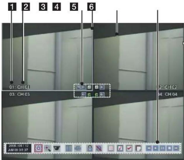
1 Channel Number
Displays the channel number.
2 CH 01 Channel Name
Displays the edited channel name.
3 Camera Status Icon

Displays the PTZ camera status.

Input audio icon
Displays the input audio status.

Recording status icon
Displays the recording status.
- Green "C" indicates continuous recording.
- Green "I" indicates Instant recording.
- Red "S" indicates sensor triggered recording.
- Blue "M" indicates motion detection recording.
- White "N" indicates the channel is not being recorded.
4 Selected Channel
Displays the selected channel with white box.
5 Live Screen
Displays the current surveillance live screen.
6 System Control Bar
| 2008/08/12AM 09:35:37 | Displays the current date and time. |
 | Displays the setup menu. |
 | Displays the search menu. |
 | Displays the PTZ remote control window. |
 | Displays in the full screen display mode to return to the 4 division screen windows. |
 | Views the all channels in sequence on the full screen display mode. You cannot use sequence mode with the 4 split.Note:The covert channel(s) or video loss channel(s) is(are) not displayed with power and normal user. |
 | Displays the lock menu to change the user type or disable system operation. |
 | Turns the alarm off. |
 | Displays the system log list window. |
 | Displays the system information window. |
 | Click at a desired point to be marked during playback. Up to 15 points can be marked. |
 | Display copy (export) menu. |
 | Select the required scanning speed. |
 | Starts instant playback in selected recording channel. If the recorded data is empty, a warning message is displayed. |
 | Pause playback. |
 | Stop playback. |
To display / remove the system control bar
- Press OSD or click the right mouse button in live screen mode and select [Control bar On/Off] option.
- Press ENTER or click the [Control bar On/Off] option and then the system control bar will be displayed or removed.
PTZ Camera Control
You can control the cameras connected via the data port of RS-485 terminal. You must set the configuration between the PTZ camera and the DVR.
-
Select the PTZ camera channel on the main monitor you want to control.
-
Press PTZ or Click the icon in the system control bar.
Virtual PTZ remote control is displayed on the main monitor.
- Use each item to control the PTZ camera.
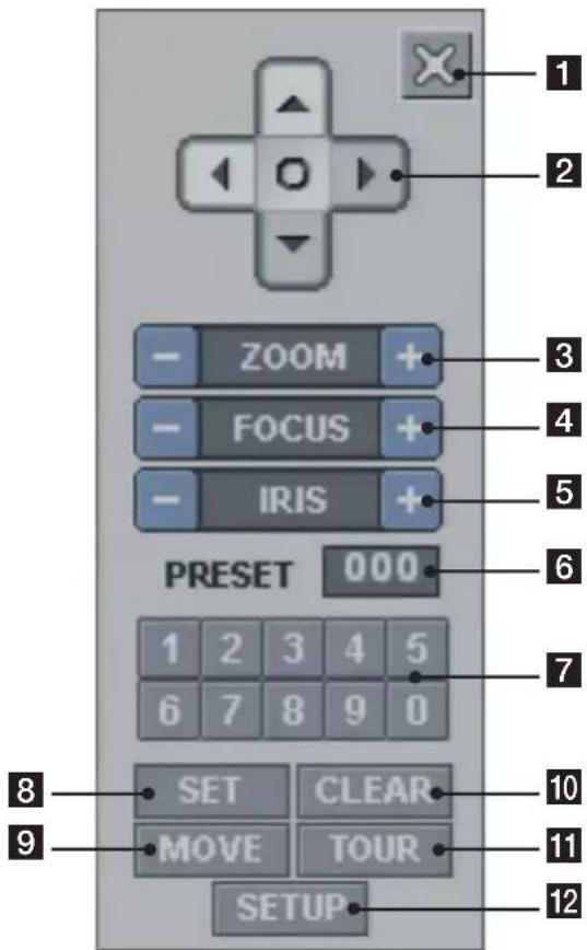
| Button Function | ||
| 1 | Remove the PTZ virtual remote control. | |
| 2 |  | Use to pan/tilt the camera. |
 | Confirm the preset position. | |
| 3 |  | To adjust the camera zoom. |
| 4 |  | To manually adjust the focus of a camera. |
| 5 |  | To manually adjust the iris of a camera. |
| 6 |  | Displays the Selected Preset Number |
| 7 |  | Number Buttons To input the preset number. |
| 8 |  | To register preset positions. |
| 9 |  | To move the camera to the preset position. |
| 10 |  | To delete a memorized preset position. |
| 11 | To start  . . | |
| 12 |  | To displays the setup menu of the PTZ camera. |
Preset Settings
Preset position is the function to register camera monitoring positions (preset positions) associated with position numbers.
By entering the position numbers, you can move cameras to the preset positions.
Note:
To activate this function, you need to register the preset positions of the PTZ cameras.
To Register Preset Positions
- Move the camera to a point you wish by using the
-
Press SET or click the icon.
-
Select the preset number you wish to register.
-
Press ENTER or click the icon.
The position and its number are memorized.
- Repeat steps 1-4 to add additional positions.
Note:
Preset numbers from 0 to 255 are available on this unit but the actual preset range differs depending on PTZ cameras.
Changing to a Picture in a Preset Position
The following function is available only with cameras provided with the preset function. The preset function makes the combination camera move to the programmed preset position. It is necessary to program preset positions for the combination camera beforehand.
-
Press the MOVE button or click the icon.
-
Use number buttons to enter the memorized preset position's index number then press ENTER or click the icon. The camera moves to the preset position and the picture of the camera in that position appears on the monitor.
To Clear the Preset Position
You can clear a memorized preset position.
- Press the CLEAR button or Click the icon.
- Use number buttons to enter the memorized preset index number then press ENTER or Click the icon to clear the preset positions.
Note:
This function may not be available depending on PTZ cameras.
To Tour The Preset Positions
You can tour all preset positions.
- Press the TOUR button or Click the icon. All registered preset positions in the camera will be selected and the camera position image will be switched on the active monitor.
- You can stop the tour by pressing the TOUR button or clicking the icon.
Setup for PTZ Cameras
You can adapt the camera to your requirements by setting up the respective items in menus.
- Click the icon.
The setup menu appears in the selected window of the main monitor. - Use // , and buttons to set the options.
Notes:
• Refer to the manuals of the PTZ camera for more details.
• Some PTZ cameras may not operate correctly with this unit.
- You cannot control the other functions when the PTZ virtual remote control is displayed.
Viewing System Information
To view system information:
- Press INFO or click the icon in the system control bar.
The system information window is displayed on the main monitor.
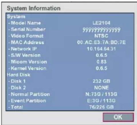
- Select [OK] and press ENTER or click the [OK] button to exit the window.
Viewing the System Log List
To view the system log list:
- Press LOG or click the icon in the system control bar.
The system log list window is displayed on the main monitor.
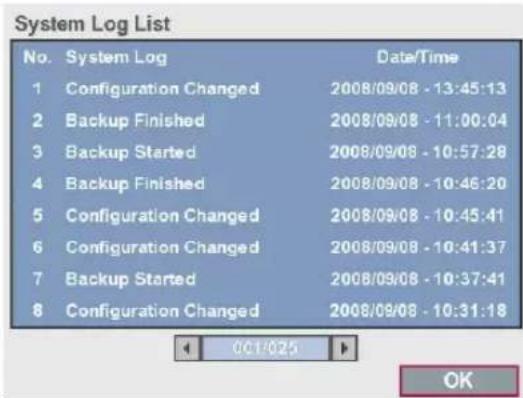
-
Use ◀/▶ to see the previous or next log list.
-
Select [OK] and press ENTER or click the [OK] button to exit the window.
Note:
The system log list.
| No. Log | Message |
| 1 | Power On |
| 2 | Power Off |
| 3 | Power Recovery |
| 4 | Admin Login (Remote) |
| 5 | Admin Logout (Remote) |
| 6 | Power User Login (Remote) |
| 7 | Power User Logout (Remote) |
| 8 | Normal User Login (Remote) |
| 9 | Normal User Logout (Remote) |
| 10 | Admin Login (Local) |
| 11 | Admin Logout (Local) |
| 12 | Power User Login (Local) |
| 13 | Power User Logout (Local) |
| 14 Normal User Login (Local) |
| 15 Normal User Logout (Local) |
| 16 Configuration Changed |
| 17 Configuration Imported |
| 18 Factory Default Set |
| 19 Backup Started |
| 20 Backup Finished |
| 21 Backup Failed |
| 22 Export Started |
| 23 Export Finished |
| 24 Export Failed |
| 25 S/W Updated |
| 26 HDD Added (HDD1) |
| 27 HDD Added (HDD2) |
| 28 HDD Removed (HDD1) |
| 29 HDD Removed (HDD2) |
| 30 HDD Formatted (HDD1) |
| 31 HDD Formatted (HDD2) |
| 32 HDD Changed (HDD1) |
| 33 HDD Changed (HDD2) |
| 34 HDD Damaged (HDD1) |
| 35 HDD Damaged (HDD2) |
Export the recorded data
This unit can manually copy recorded images and audio from built-in HDD to the external recording devices.
- Press COPY or click the bar.

The export menu window appears.
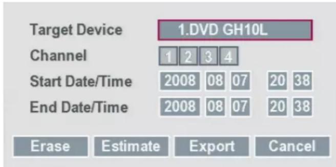
- Select [Target Device] then press ENTER.
- Use ◀/▶ to select a target device to export.
- Press ENTER to confirm it.
- Select the channel number and press ENTER. Repeat this step to select multi channels.
- Set the [Start Date/Time] and [End Date/Time] to copy.
• ◀/▶/▲/▼: Moves to the options.
• ◀/▶: Sets the selected option.
• ENTER: Selects option or confirms the setting.
- Select [Export] and press ENTER or click [Export] icon to start exporting. The exported data will be authorized by the unit before saving and it can only be played back with the exclusive player.
Notes:
- You can also use the COPY button on the front panel for export function.
- Check the export device before you proceed.
• You can export the recorded data only in the live mode. -
If you use the external USB memory device, the external USB memory device has to be formatted on this unit.
-
Connect the USB memory device to the USB port on the front or the rear of the DVR.
- Select the [Erase] icon then press ENTER. Confirm window is displayed after format is completed.
- Select [OK] and press ENTER to close the window.
- Check the size of the selected data and free space of the external device. If the device has not enough space, create space on the device or erase the previously stored data.
- Select the [Estimate] icon and press ENTER. The size of the selected data and free space is displayed.
-
Select [OK] and press ENTER to close the window.
-
Export can not be executed while the backup is in progress.
- You can search the exported data with the supplied viewer software.
- When you export the recorded data, the audio data will also be exported.
- When you export the recorded data the export viewer program will also be exported in the [ExportViewer] folder of the device. The exported data file name is made automatically as the [Channel name_export date_export time.exp] type.
- Do not remove the USB device while the export is in progress, it may cause a malfunction. If you reuse the removed device, you must format the media by using erase options.
-
The warning message appears for the conditions listed below.
-
When the start date/time and end date/time are the same value.
- When the start date/time is later than the end date/time.
- The export media does not have enough space.
-
When you set the time for data that does not exist.
-
An external media has to be formatted on this unit to prevent a malfunction.
- DVD+RW and DVD-RW discs have to be initialized before using.
- You can format the external media with the [Erase] option.
Configuration menu
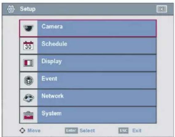
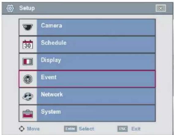
The features and options of the DVR are configured through the menu. The operations of this unit can be set via a menu displayed on the main monitor. You can select and set the operational conditions by using the buttons on the front panel and the remote control or using a Mouse connected to the unit.
Only administrator-level users have permission to access the Setup menu and configure the DVR.
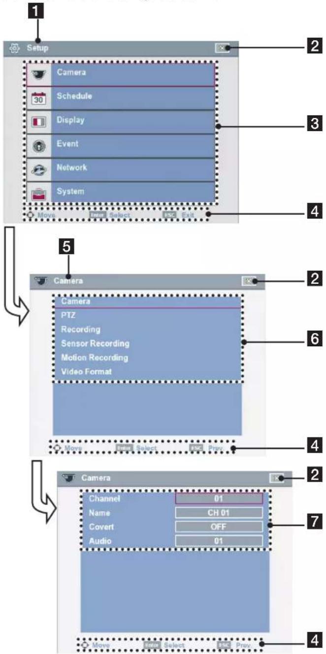
1 Displays the main menu title.
2 Returns to the previous menu or exits the setup menu.
3 Displays the main menu.
4 Displays the help menu.
5 Displays the selected submenu title.
6 Displays the submenu options.
7 Displays the detail options for selected submenu.
Using a mouse to set a menu
Use the left or right mouse buttons to set the menu.
| Button Function | ||
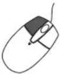 | Left button | Use to select a required item or decrease the options value.If you double click the button, you can see the selected channel on the full screen. |
 | Right button | Use to increase the options value.Displays the sub-setup menu in the live screen mode. |

- Click the icon on the bottom of the on-screen display with the left mouse button to display a setup menu.
- Click the desired option with the left mouse button to move to the second or third menu level.
- Click the desired option with the left mouse button.
- Set the selected options value.
- Click the icon repeatedly to exit setup menu. If the save message appears, click button with the left mouse button to save the settings.
Setting the Menu Using the Front Panel Buttons or Remote Control Buttons
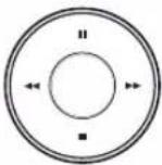 |  | Use these buttons to select the menu options or adjust the options value. |
 |  | Select the option or confirm the setting. |
 |  | Return to the previous menu or level. |
- Press SETUP/ESC to display the setup menu.
- Use ▲/▼ to select the desired menu item, then press ENTER to display the submenu.
- Use ▲/▼ to select the desired submenu item, then press ENTER to display the setting options.
- Use ▲/▼ to select the desired option then press ENTER to set the value.
- Use ◀/▶ to select the desired setting then press ENTER to confirm your selection.
- Press SETUP/ESC repeatedly to exit the Setup menu. If the save message appears, select [OK] and press ENTER to save the settings.
Notes:
- When you operate the function menu by using the remote control and front panel buttons, both buttons are operated in the same way to control the function menu.
- All the operation explanations are based on using the remote control.
Camera settings
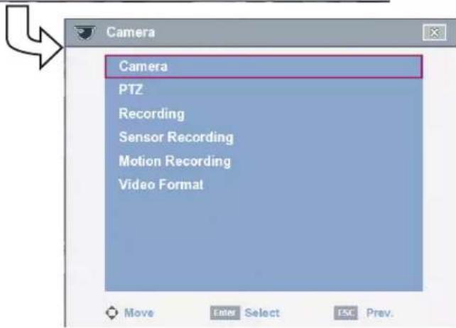
Camera
The channel name, covert and input audio channel settings are configured.
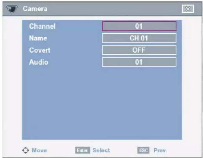
• Channel: Selects the desired channel to set the options.
- Name: Enter the channel name using up to 12 characters.
- ◀/▶/▲/▼: Use to move the columns, [OK] or [Cancel] button. Select a character.
- ENTER: Confirms your selection.
- Select [OK] and press ENTER to save the channel name.
-
Select [Cancel] and press ENTER to exit the virtual keyboard menu.
-
Covert: You can set the camera conditions to prevent operation by other users. If the covert option is set to ON, "LG logo" is displayed on the live window with POWER or NORMAL user.
• Audio: You can connect the audio input with a specified camera input.
PTZ
Settings for the PTZ cameras connected via the data port of the RS-485 terminal.
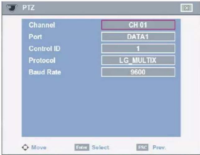
• Channel: Selects the desired channel to set the connected PTZ camera.
- Port: Selects the connected data port of the RS-485 terminal on the rear panel. The D2 (DATA 2) port is used to control the PTZ camera connected to DVR or to control by using the LKD1000 controller. If you want to use the PTZ camera via D2 (DATA 2) port, you should set the DVR ID to "NONE" on the system setup menu. If you use the LKD1000 controller to control the DVR via D2 (DATA 2) port, you should set the DVR ID number (01 to 16) on the system setup menu.
• Control ID: Selects the PTZ camera ID from 0 to 255. Make the same settings as the PTZ camera.
- Protocol: Selects the protocol supported by PTZ camera. The supported PTZ camera list is on page 64 for reference.
• Baud Rate: Selects the communication speed. (1 200, 2 400, 4 800, 9 600 or 19 200)
Recording
Settings concerning normal recording.
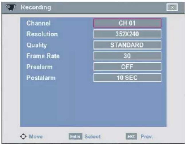
• Channel: Selects the desired channel to set the options.
• Resolution: Selects the recording resolution.
• Quality: Selects the recording picture quality (LOWEST, LOW, STANDARD, HIGH or HIGHEST).
- Frame Rate: Selects the frame rate. The frame rate is the number of recorded frames per second. According to resolution, the frame rate is set automatically. If you wish to set manually, refer to the below.
| Resolution Frame Rate | |
| NTSC | 352 x 240 1, 3, 5, 7.5, 15, 20, 30 |
| 704 x 240 1, 3, 5, 7.5, 15 | |
| 704 x 480 1, 3, 5, 7.5 | |
| PAL | 352 x 288 1, 3, 5, 6, 12.5, 20, 25 |
| 704 x 288 1, 3, 5, 6, 12.5 | |
| 704 x 576 1, 3, 5, 6 | |
- Prealarm: Specify the pre-event recording time that records the situation until the sensor alarm signal has input or motion has been detected. (OFF, 5, 10, 20, 30, 40, 50 or 60 SEC)
- Postalarm: Specify the post-event recording time that records the situation from when the sensor alarm signal has input or motion has been detected. (10, 20, 30, 40, 50 SEC or 1, 2, 3, 5, 10 MIN)
Note:
The setting values of Prealarm and Postalarm options are also used as the same ones for Sensor Recording and Motion Recording function.
Sensor Recording
Settings concerning sensor recording.
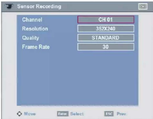
• Channel: Selects the desired channel to set the options.
• Resolution: Selects the recording resolution.
• Quality: Selects the recording picture quality (LOWEST, LOW, STANDARD, HIGH or HIGHEST).
- Frame Rate: Selects the frame rate. The frame rate is the number of recorded frames per second. According to resolution, the frame rate is set automatically. If you wish to set manually, refer to the below.
| Resolution Frame | Rate | |
| NTSC | 352 x 240 1 | 3, 5, 7.5, 15, 20, 30 |
| 704 x 240 1 | 3, 5, 7.5, 15 | |
| 704 x 480 1 | 3, 5, 7.5 | |
| PAL | 352 x 288 1 | 3, 5, 6, 12.5, 20, 25 |
| 704 x 288 1 | 3, 5, 6, 12.5 | |
| 704 x 576 1 | 3, 5, 6 | |
Motion Recording
Settings concerning motion recording.
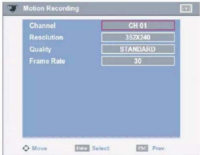
• Channel: Selects the desired channel to set the options.
• Resolution: Selects the recording resolution.
• Quality: Selects the recording picture quality (LOWEST, LOW, STANDARD, HIGH or HIGHEST).
- Frame Rate: Selects the frame rate. The frame rate is the number of recorded frames per second. According to resolution, the frame rate is set automatically. If you wish to set manually, refer to the below.
| Resolution Frame | Rate | |
| NTSC | 352 x 240 1 | 3, 5, 7.5, 15, 20, 30 |
| 704 x 240 1 | 3, 5, 7.5, 15 | |
| 704 x 480 1 | 3, 5, 7.5 | |
| PAL | 352 x 288 1 | 3, 5, 6, 12.5, 20, 25 |
| 704 x 288 1 | 3, 5, 6, 12.5 | |
| 704 x 576 1 | 3, 5, 6 | |
Video Format
Selects the video format to NTSC or PAL according to your video system format.
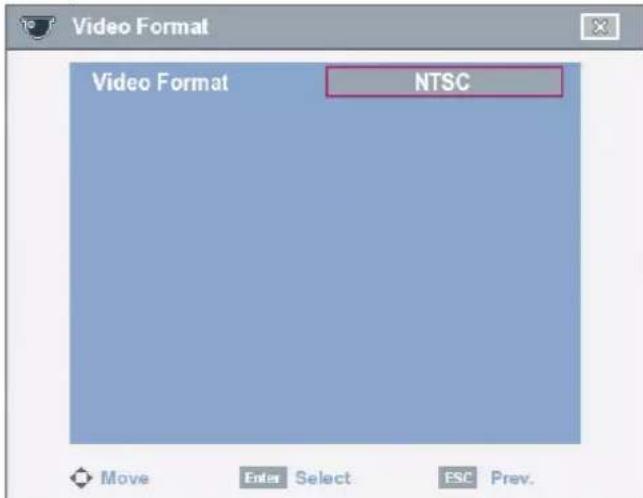
- Select the video format. The confirmation message is displayed.
- Select [OK] and press ENTER. After the HDD has been formatted, the system will reboot.
Note:
All cameras must be disconnected before you change the video format to prevent malfunction.
Video Adjustment
Adjust the brightness, contrast and color settings of each camera channel.
- Select the desired channel in live screen mode to adjust the options.
- Press OSD or click the right mouse button to display the sub-setup menu.
- Select [Video Adjustment] option and press ENTER. Video Adjustment menu is displayed.
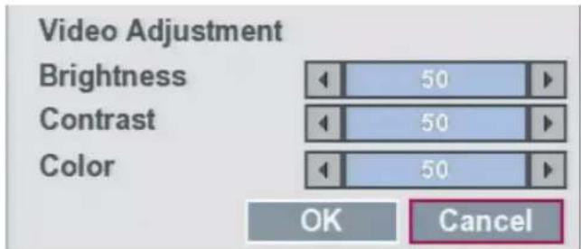
- Selects the desired option and press ENTER.
- Use ◀/▶ to adjust the value.
- Brightness: Adjust the brightness value from 01 to 100 for the selected channel.
- Contrast: Adjust the contrast value from 01 to 100 for the selected channel.
• Color: Adjust the color value from 01 to 100 for the selected channel.
- Select [OK] icon and press ENTER to confirm your settings.
- Select [Exit] and press ENTER to exit the sub-setup menu.
Note:
This function is not activated for spot out channel.
Schedule settings
The DVR can record according to a schedule set by the user. It can also record manually regardless of date and time. The recording can be made either continuously or triggered by events (alarm and motion detection).
The recording schedule screen displays the selected day showing the schedule of all channels over a 24-hour period.
For each 1-hour cell block the recording method can be specified. The recording method for each block is shown in color for easy viewing.
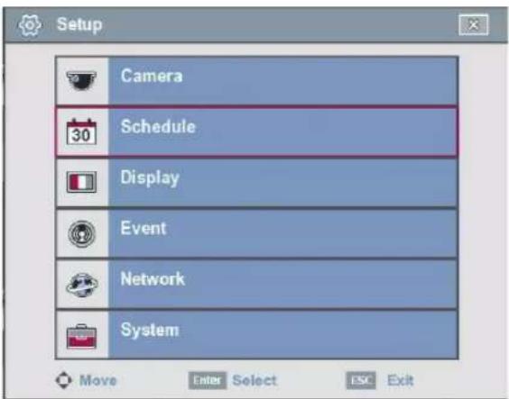
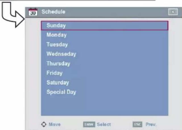
To Set the Recording Schedule for a Typical Day of the Week
1. Select a day of the week.
The recording schedule screen is displayed.
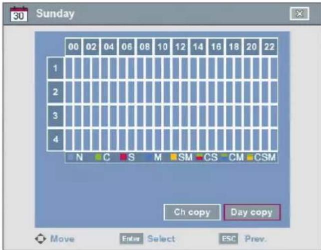
- Select the desired channel to schedule recording.
- Select the time cell block for the start time and press ENTER.
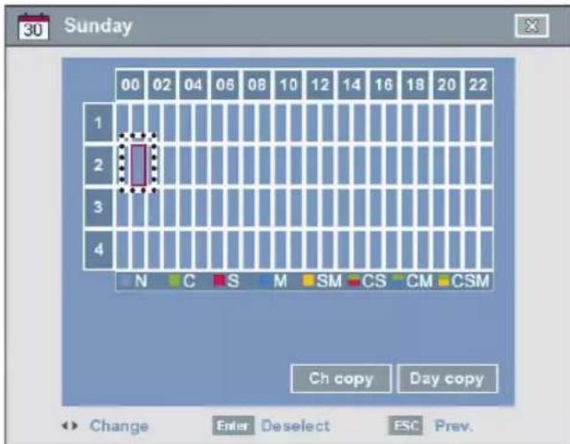
-
Use ◀/▶ or click the left mouse button to select a recording mode. The color of the cell blocks will change automatically.
-
Gray: No scheduled recording.
- Green (Continuous recording): Recording starts automatically from the preset time.
- Red (Sensor event recording): Recording starts automatically when the sensor alarm is occurs within a designated time.
- Blue (Motion event recording): Recording starts automatically when motion is detected within a designated time.
-
Yellow (Sensor+Motion recording): Recording starts automatically when the sensor alarm signal has input or motion has been detected.
-
Green+Red (Continuous+Sensor event recording): Recording starts automatically from the preset time. When the sensor alarm occurs within a designated time, change the continuous recording mode to sensor event recording mode and recording starts automatically.
- Green+Blue (Continuous+Motion event recording): Recording starts automatically from the preset time. When the motion is detected within a designated time, change the continuous recording mode to motion event recording mode and recording starts automatically.
-
Green+Yellow (Continuous+Sensor+Motion event recording): Recording starts automatically from the preset time. When the sensor alarm signal has input or motion has been detected, change the continuous recording mode to motion event recording mode and recording starts automatically.
-
Select the next time cell block of schedule time cell blocks to confirm the schedule time and press ENTER.
- Use ◀/▶ or click the left mouse button repeatedly to select gray to set the time for the end of the schedule. The settings cell block is highlighted.
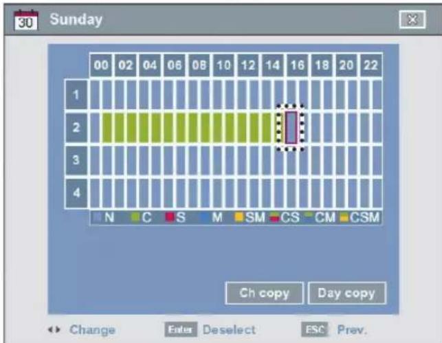
- Press SETUP/ESC to move to the previous menu. If the save message appears, select [OK] and press ENTER to save the settings.
- Press SETUP/ESC repeatedly to exit the Setup menu.
To Set a Recording Schedule for a Special Day
In addition to the weekly schedule, up to 10 specific date/time periods can be defined. To configure the specific recording schedule select Specific Dates.
- Select the [Special Day] option.
- Select the [Add] icon.
The specific date selection menu appears.
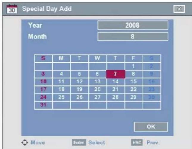
- Enter the necessary information for year, month and date.
• ◀/▶/▲/▼: Press to move the columns.
- ◀/▶ (or left/right mouse button): Changes the value at the current position.
• ENTER: Confirms your selection.
4. Use ◀/▶/▲/▼ to select [OK] button and press ENTER.
The virtual keyboard menu appears.
5. Enter the name of the special day. Use ◀/▶/▲/▼ to select a character then press ENTER to confirm your selection.
6. Use ▲/▼ to select the [OK] button then press ENTER to fix the date of the special day and return to the special day recording schedule screen.
7. Select the schedule time and set the recording method for each channel.
8. Press SETUP/ESC to move to the previous menu. If the save message appears, select [OK] and press ENTER to save the settings.
9. Press SETUP/ESC repeatedly to exit the Setup menu.
Checking the Special Day Schedule List
- Select the [Special Day] option.
- Select the [List] icon. The special day scheduled list appears.
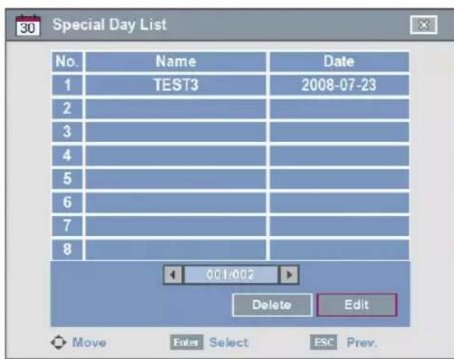
- Select a special day title on the list and press ENTER. The title color turns red.
- Select the [Edit] icon then press ENTER to edit the special day or select the [Delete] icon to delete the special day schedule.
- Press SETUP/ESC to exit the special day schedule list.
Note:
If the special day recording schedule is duplicated with the other recordings, only the special day recording is possible.
Copying the Recording Schedule
Copying from the Scheduled Data of the Channel
You can copy the schedule data of the channel to the other channel(s) within the selected day of the week.
- Select the day of the week and press ENTER.
- Select channel that you want to copy and press ENTER.
- Select the [Ch copy] icon then press ENTER. The channel selection menu appears.
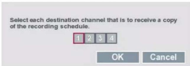
- Use ◀/▶ to move to the left or right column then press ENTER to select the target channel(s). You can cancel the selected channel by pressing ENTER.
- Use ▲/▼ to select [OK] then press ENTER to confirm your selection.
Copying from the Scheduled Data of the Day
You can copy the scheduled day of the week to another day of the week, weekday and weekend.
- Select the day of week that you want to copy and press ENTER.
- Select the [Day copy] icon then press ENTER. The select date(s) menu appears.
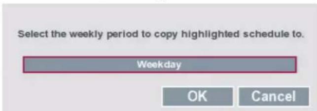
- Use ◀/▶ to select the target date(s).
- Use ▲/▼ to select [OK] then press ENTER to confirm your selection.
Display settings
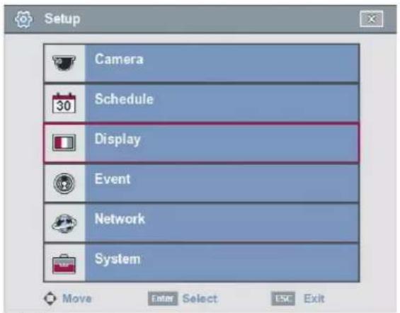
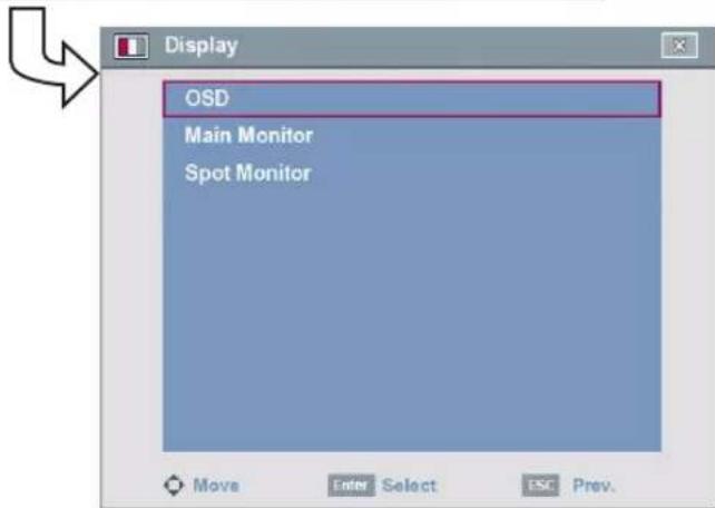
OSD
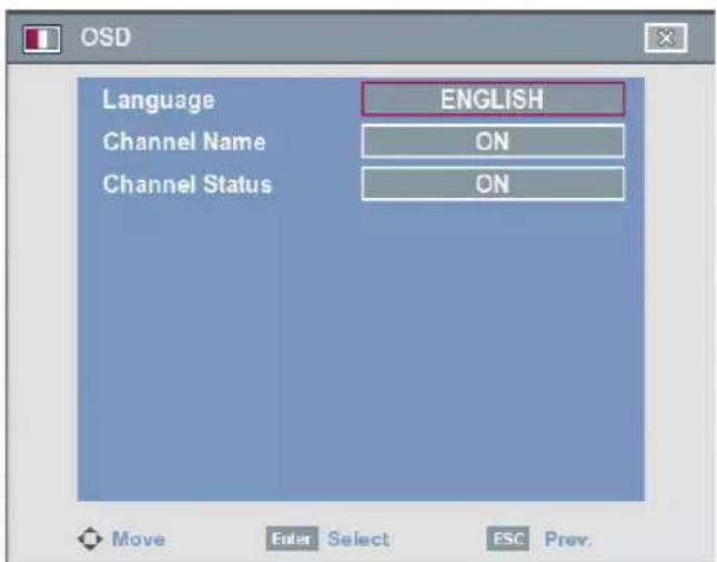
• Language: Select a language for the setup menu and information display.
- Channel Name
- ON: Displays the title of the channel.
- OFF: Displays the live picture without the title of the channel.
- Channel Status
- ON: The current channel recording status is displayed.
- OFF: Remove the current channel recording status.
Main Monitor
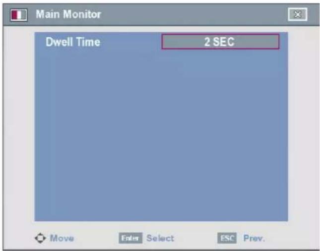
- Dwell Time: You can set the channel sequence time to 2 SEC, 5 SEC, 10 SEC, 20 SEC, 30 SEC, 40 SEC, 50 SEC, 60 SEC, 70 SEC, 80 SEC or 90 SEC.
Spot Monitor
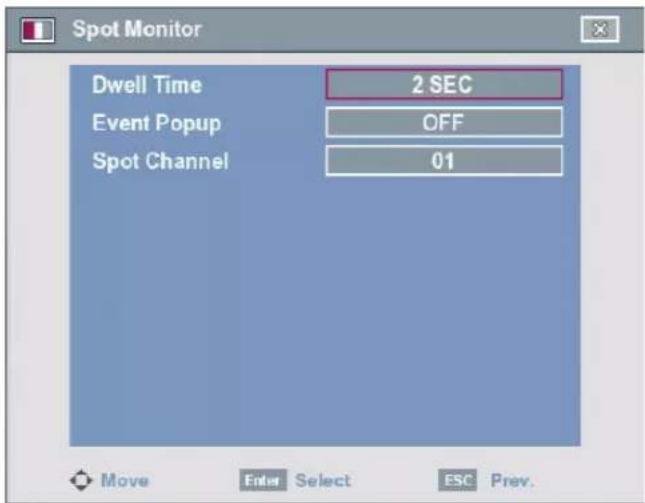
- Dwell Time: You can set the channel sequence time to 2 SEC, 5 SEC, 10 SEC, 20 SEC, 30 SEC, 40 SEC, 50 SEC, 60 SEC, 70 SEC, 80 SEC or 90 SEC.
- Event Popup: Displays an event popup on the spot monitor if motion, sensor or all (motion or sensor) occur.
-
Spot Channel: Selects the desired spot channel.
-
01 to 04: Views the selected channel's surveillance image on the spot monitor.
- SEQUENCE 1: Views the all channels in sequence. The covert channel(s) or video loss channel(s) is(are) not displayed with power and normal user.
- SEQUENCE 2: Views the all channels in sequence except the covert channel(s) and video loss channel(s).
Event Settings
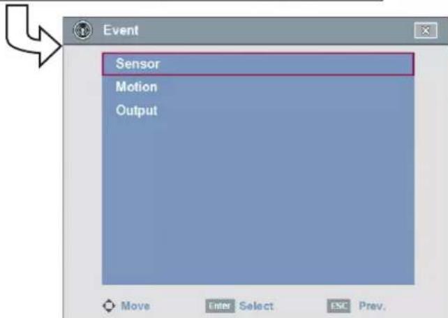
Sensor
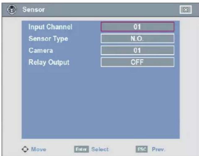
- Input Channel: Select the number of the ALARM-IN terminal.
- Sensor Type: The sensor state can be set to either N.O. (Normally Open) or N.C. (Normally Closed).
• Camera: Select the connected camera channel to the ALARM-IN terminal. - Relay Output:
- ON: Outputs the alarm (relay) signal via the ALARM-OUT terminal.
- OFF: Not used.
Motion
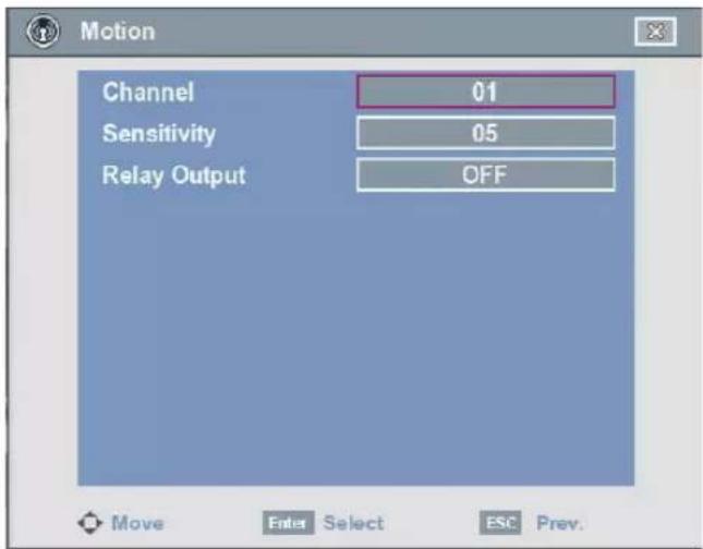
• Channel: Select the channel to set motion detection.
- Sensitivity: Set the level of sensitivity for the created motion detection area. Sensitivity can be set from level 01 to 10 or NONE.
- Relay Output:
- ON: Outputs the alarm (relay) signal via the ALARM-OUT terminal.
-OFF: Not used.
Notes:
- In the condition that illumination is low and the outline of object is not clear enough to see, regardless of sensitivity, Motion Event could be possible not to happen. You must check Motion Event before setting.
-
Motion area setting
-
Select the desired channel in live screen mode.
-
Press OSD or click the right mouse button to display the sub-setup menu.
-
Select [Motion] option and press ENTER.
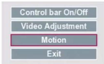
- Select the desired motion detection area on the selected channel window screen.
• Using the Remote control
- ◀/▶/▲/▼: Move the cell box to another cell zone.
- ENTER: Selects or cancels the motion detection area at the current cell position.
• Using the Mouse
- To select the area: Drag & drop a cell to the right to select the motion detection area.
-
To cancel area: Drag & drop a cell point of a selected cell area to the left to cancel the motion detection area.
-
Click the right mouse button to exit the settings.
- Select [Exit] and press ENTER to exit the sub-setup menu.
Output
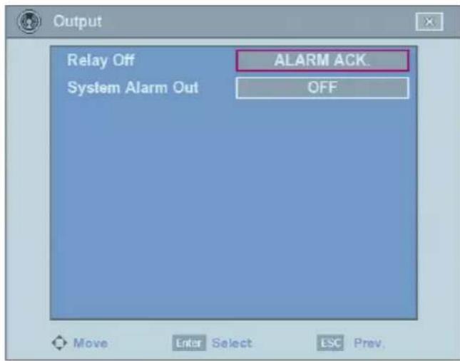
- Relay Off
- ALARM ACK.: Use the ALM.OFF button to stop alarm.
- POST-ALARM TIME: The alarm is stopped after post-alarm time.
• System Alarm Out:
- ON: Outputs the alarm (relay) signal via the ALARM-OUT terminal below cases.
When the HDD has bad sector.
When a video signal from the camera has stopped because of a cable disconnection or malfunction of a camera.
- OFF: Not used.
Network Settings
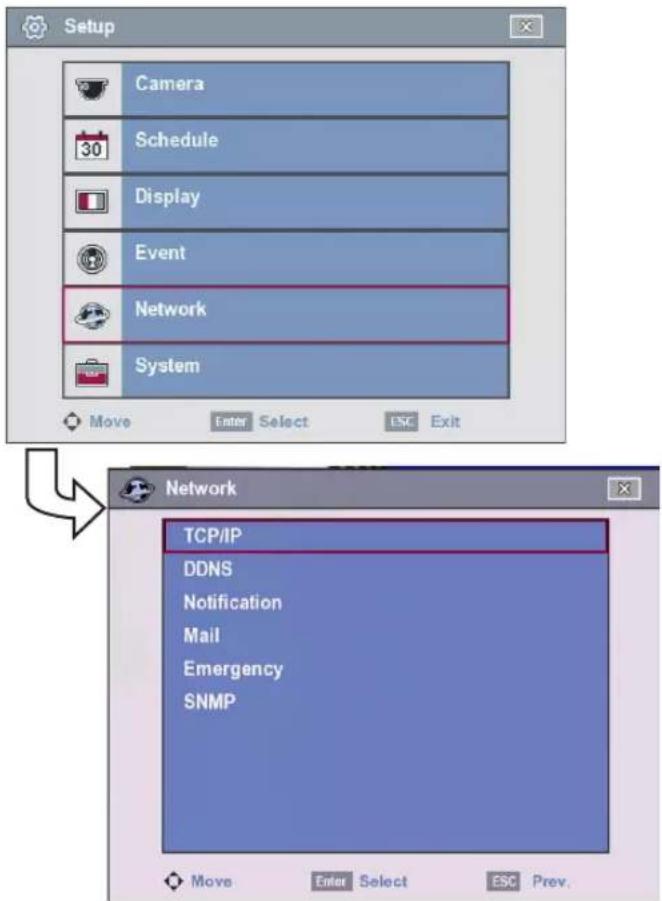
TCP/IP
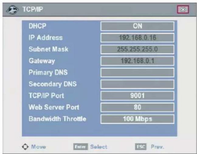
- DHCP: DHCP stands for Dynamic Host Configuration Protocol.
- ON: Network settings of this unit are configured automatically by the DHCP server. You can use the DDNS function instead of the dynamic IP address. (For more details refer to the DDNS settings.) If you set to ON, the [IP Address], [Subnet Mask], [Gateway], [Primary DNS] and [Secondary DNS] options are not set.
-
OFF: Enter the network settings manually.
-
IP Address: Enter an IP address using the virtual keyboard.
- Subnet Mask: Enter a subnet mask address using the virtual keyboard.
- Gateway: Enter the gateway address using the virtual keyboard.
• Primary DNS: Enter the Main DNS server address using the virtual keyboard.
• Secondary DNS: Enter the Sub DNS server address using the virtual keyboard. - TCP/IP Port: Enter the TCP/IP Port number using the virtual keyboard. You can watch the live surveillance image over the network with the PC Client program.
The factory default port for transmission of video and audio data is 9001. However in some cases it is better to change this port number for added flexibility or security. If desired change the port number (1025 to 65 535). - Web Server Port: Enter the Web server Port number using the virtual keyboard. You can watch the live surveillance image over the network with a web browser. Typically the TCP port used by HTTP is 80. However in some cases it is better to change this port number for added flexibility or security. If desired change the port number (80 or 1025 to 65 535).
- Bandwidth Throttle: Select the Bandwidth to adjust the data traffic.
Note:
When you change the TCP/IP port or web sever port number, all connections with the PC Client programs or web browser will be disconnected.
DDNS (Dynamic Domain Name System)
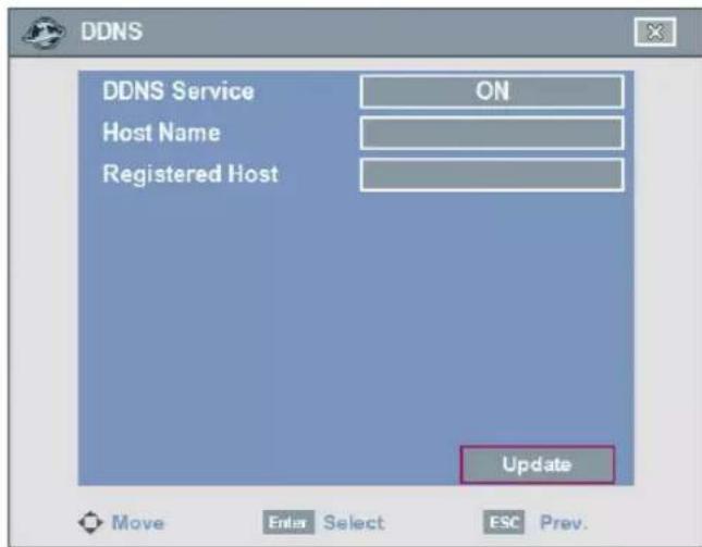
- DDNS Service:
- ON: Select to enable DDNS function. This free service is very useful when combined with the LG DDNS Server. It allows Internet users to connect the LG DDNS Server using a Host Name, rather than an IP Address. This also solves the problem of having a dynamic IP address. With a dynamic IP address, your IP address may change
whenever you connect, which makes it difficult to connect to you.
- OFF: The DDNS function is not used.
- Host Name: Using the virtual keyboard, enter the host name you want to use.
• Registered Host: The registered host name appears. - Update: Register the host name you typed in [Host Name] to LG DDNS server.
Note:
Check the network settings before using this function. You might have to properly configure your network settings to use this function.
How to register DDNS host name
With the DDNS function, you can easily use LG DVR.
When you use the DDNS function for the first time after you purchased LG DVR
- Displays the DVR setup menu.
- Select [Network] > [DDNS] option.
- Set the [DDNS Service] to [ON].
- Enter the host name in [Host Name] option.
- Select the [Update] icon and press ENTER. If host registration is properly completed, the host name will be displayed in [Registered Host] option.
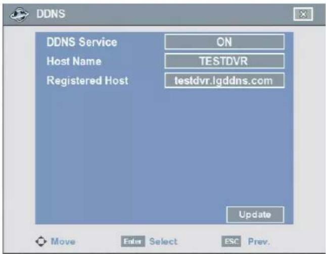
Note:
If the host name is not registered after updating, please check network connection.
When you want to change DDNS host name
If you want to change the registered host name to new one, follow as shown below.
- Enter a new host name in [Host Name] option.
- Select the [Update] icon and press ENTER. The confirmation window will be displayed to change your host name.
![DDNS DDNS Service Host Name Registered Host ON TESTDVR-UP testdvr.lgddns.com You have registered the host [ testdvr.lgddns.com ] before. Do you want to delete the host and register new one? OK Cancel Update Move Enter Select ESC Prev.](/content/2026/05/956624/images/f1c41de4a1ac228ce5b897b303814244ac8c64d6aefff998dce34de2885bc916.jpg)
- Select the [OK] and press ENTER.
When host name is properly changed, the changed host name will be displayed in [Registered Host].
Note:
If host name is not changed after updating, please check network connection.
Notification
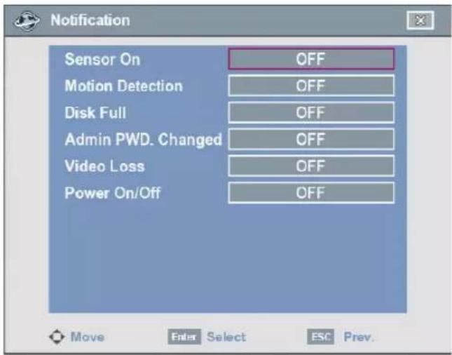
- Sensor On:
- ON: Sends an e-mail when a sensor has occurred.
- OFF: Not used.
- Motion Detection:
- ON: Sends an e-mail when a motion detection has occurred.
- OFF: Not used.
- Disk Full:
- ON: Sends an e-mail when the HDD has fully recorded.
- OFF: Not used.
• Admin PWD. Changed:
- ON: Sends an e-mail when the administrator password has changed.
- OFF: Not used.
- Video Loss:
- ON: Sends an e-mail when a video signal from the camera has stopped because of a cable disconnection or malfunction of a camera.
- OFF: Not used.
• Power On/Off:
- ON: Sends an e-mail when power is on.
- OFF: Not used.
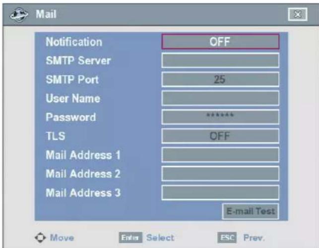
- Notification
- ON: Notifies the user of unit operating information by e-mail according to notification settings.
- OFF: The notification function is not used. The mail options are not set.
- SMTP Server: Enter the SMTP Server address using the virtual keyboard.
If notification is set to ON and the SMTP server option is empty, the SMTP Port, User Name, Password and TLS options are not set.
- SMTP Port: Enter the SMTP Port Number using the virtual keyboard. Typically the port used for SMTP is 25. However in some cases it is better to change this port number for added flexibility or security. If desired change the port number (1 to 65 535).
- User Name: Enter the user name using the virtual keyboard.
- Password: Enter the password using the virtual keyboard.
- TLS: Set to ON when using the TLS (Transport Layer Security) function. By default, TLS is OFF.
- Mail Address (1 to 3): Enter the mail address using the virtual keyboard.
You can input up to 3 e-mail addresses.
• E-mail Test: Select [E-mail Test] to test send an e-mail.
Note:
The SMTP server, SMTP port no., user name or password settings are optional. The DVR can send e-mail directly without the use of an SMTP server or MTA (message transfer agent). In certain cases all e-mail should be forwarded to a specific SMTP server. Specify the server host name or IP address in such a case. For more detail on SMTP setup, ask your network administrator and/or mail service provider.
Emergency
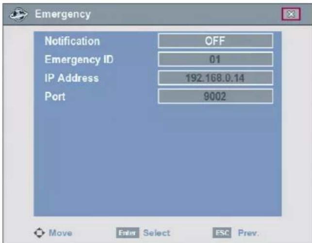
- Notification
- ON: Notifies the emergency agent about unit operating information according to your notification settings.
- OFF: Notification function is not used. If you set to OFF, the Emergency ID, IP Address and Port options are not set.
• Emergency ID: Select the emergency ID of the emergency agent program.
• IP Address: Enter the IP address of the emergency agent program using the virtual keyboard.
- Port: Enter the port number of the emergency agent program using the virtual keyboard. The factory default port for this function is 9002. However in some cases it is better to change this port number for added flexibility or security. If desired change the port number (1025 to 65 535). You can set up to 9 IP/port numbers.
SNMP
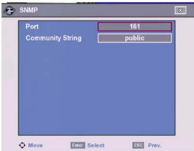
- Port: Enter the SNMP Port Number. Typically the port used for SNMP is 161. However in some cases it is better to change this port number for added flexibility or security. If desired change the port number from 1 to 65 535.
• Community String: Enter the Community name.
System Settings
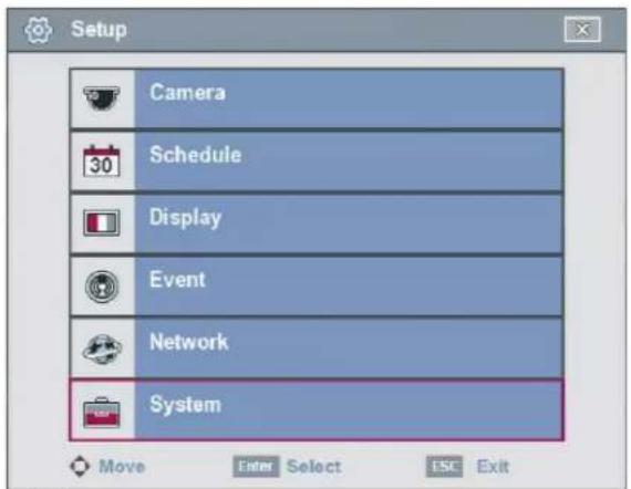
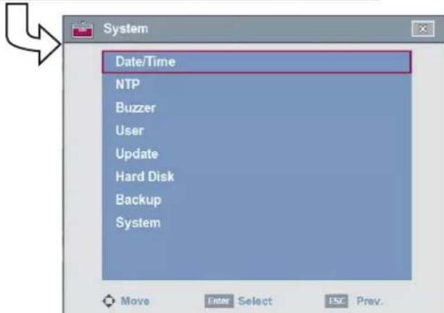
Date/Time
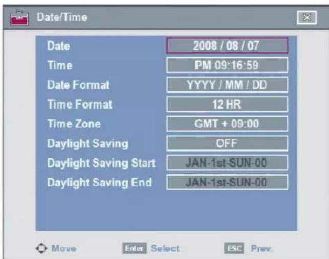
• Date: Enter the current date.
• Time: Enter the current time. (24 HR or 12 HR)
• Date Format: Select the date display format.
• Time Format: Select the time display format.
• Time Zone: Select your Time Zone.
(For more details refer to Time Zone table on page 65)
- Daylight Saving: Set to ON to you use the daylight saving function.
• Daylight Saving Start: Select the Daylight Saving start time.
- Daylight Saving End: Select the Daylight Saving end time.
Caution:
If you change the time setup, warning message will be displayed. For example, if you delay the time by 10 minutes, the overlapped 10minutes data can be deleted.
NTP
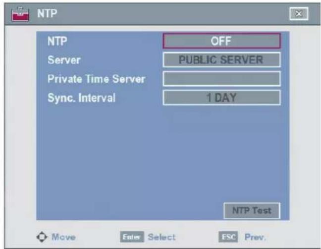
- NTP: Set to ON when using the NTP (Network Time Protocol) server for time adjustment. If the NTP is set to OFF, the time settings should be entered manually and the [Server], [Private Time Server], [Sync. Interval] and [NTP Test] options are not set.
- Server: Select your time server. For most cases select public. The DVR will obtain the average time among 5 public servers (time.nist.gov, time-a.nist.gov, time-b.nist.gov, ntp.nasa.gov, clock.isc.org).
- Private Time Server: Enter the private time server's IP address or host name using the virtual keyboard.
- Sync. Interval: You can set synchronized intervals with the NTP time server to 1 day, 1 hour, 1 month and 1 week.
• NTP Test: Select [NTP Test] to test the NTP server.
Note:
If the NTP option is not set to this system, there can be a gap between the system time and actual time. Using NTP is recommended.
Buzzer
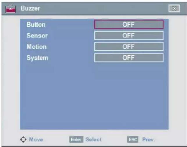
- Button
- ON: Makes a sound when using the buttons.
- OFF: Turns off the button beep.
- Sensor
- ON: Makes a sound when a sensor occurs.
- OFF: Turns off the sensor buzzer.
- Motion
- ON: Makes a sound when a motion is detected.
- OFF: Turns off the motion buzzer.
- System
- ON: Makes a sound when the HDD has a bad sector.
- OFF: Turns off the system buzzer.
Note:
The sensor and motion buzzer have low sound on this unit. If you want to make a loud sound, connect an external alarming device to the ALARM-OUT terminals (ex. Siren).
User
You can register a new user with various access rights to the DVR or client program.
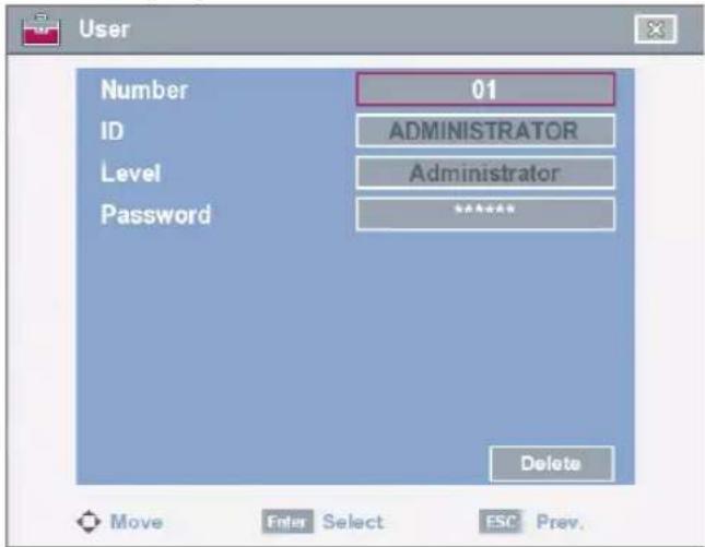
• Number: Select the number to add new user ID or change the user ID, user level or password.
• ID: Enter the new user ID using the virtual keyboard.
• Level: Select the level of the new user.
- Password: Enter or change the password for the user using the virtual keyboard. You can use the password with number, special character or characters. (Minimum 4 length, Maximum 8 length)
Note:
Remember the password. If you forget the password please contact an authorized service center or the store where you purchased the system.
Update
The update feature allows you to upgrade DVR software and add/upgrade PTZ protocols. In this case, the current DVR settings are not deleted or replaced during the update process.
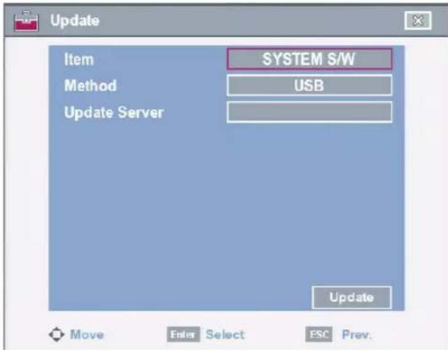
-
Select one of the following:
-
Select SYSTEM S/W to upgrade DVR system software.
-
Select PTZ PROTOCOL to update the DVR protocols.
-
Choose the media from which to perform the update:
-
USB: Select USB, and then insert the USB drive into the DVR. All USB devices must be disconnected before you can use the USB drive.
• NETWORK: Select NETWORK, and then do following:
1) Select the update server settings box. The virtual keyboard is displayed.
2) Enter the update server IP address. The DVR network settings must be configured and you must know the update server's IP address.
- Select [Update] and press ENTER to start the update process.
- Select [OK] and press ENTER to begin the update process or select [Cancel] to stop and exit. After the update process is completed, the system displays the dialogue box for system restarting.
- Select [OK] and press ENTER to restart the DVR.
Note:
You should install one of the formatted HDD for update. If you do not install the HDD, the update will not work properly.
Hard Disk
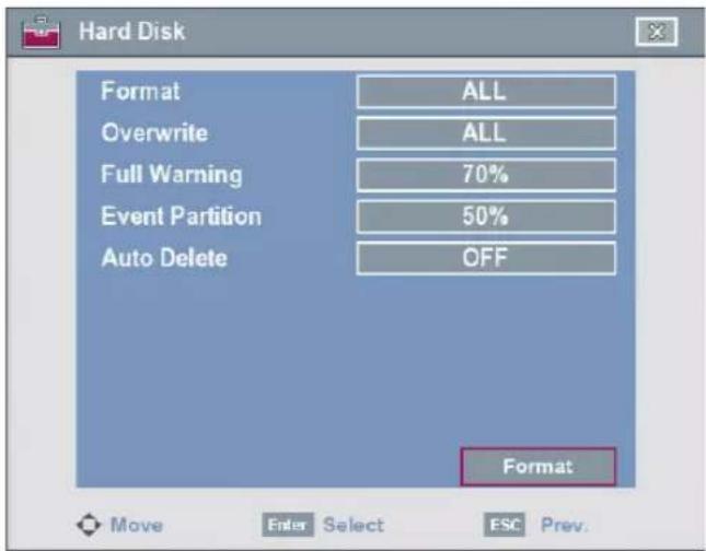
- Format: Initializes the HDD (Hard Disk Drive). All data on the selected HDD will be erased.
How to format the HDD
-
Select the [Event Partition] option and set the event partition rate of the HDD. If you set the event partition to 60 %, the remaining space of 40 % is set to normal partition automatically.
-
Event Partition: To save space of the HDD for motion and sensor recording data.
-
Normal Partition: To save space of the HDD for instant or normal recording data.
-
Select the [Format] icon and press ENTER.
- Select [OK] and press ENTER to start format.
• Overwrite:
- ALL: Overwrite recording is possible when the normal partition and event partition of HDD have fully recorded.
- NORMAL PARTITION: Overwrite recording is possible for normal partition of HDD when the normal partition of HDD has fully recorded.
- EVENT PARTITION: Overwrite recording is possible for event partition of HDD when the event partition of HDD has fully recorded.
- OFF: Do not use overwriting.
• Full Warning: When the HDD has overflowed a warning message is displayed.
• Event Partition: Set the space of event partition for event recording.
Note
The motion and sensor recording data are saved in the event partition area of the HDD. You should set the space of event partition before event recording.
- Auto Delete: Set the auto delete date (OFF, 1 DAY, 2 DAYS, 5 DAYS, 10 DAYS, 20 DAYS, 30 DAYS, 40 DAYS, 50 DAYS or 60 DAYS). If you set the auto delete date, the recorded data will be deleted except the data within the selected date period of time. The Auto Delete function is activated every 35 minutes.
Note:
If you change the value of event partition, the current recorded data of HDD is deleted and the partition is reset. The partitions will be formatted automatically and the system will be restarted.
Backup
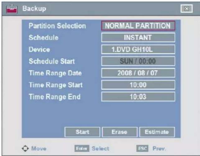
• Partition Selection: Select a backup partition.
• Schedule: You can set the backup schedule.
- OFF: If the schedule is set to OFF, the Schedule Start, Time Range Date, Time Range Start and Time Range End options are disabled.
- INSTANT: The backup data is saved manually.
- WEEKLY or DAILY: The backup data will be automatically saved according to the setting.
• Device: Select a backup device.
- Schedule Start: Set the schedule start date (A day of the week and time).
• Time Range Date: Enter the date you want to backup.
- Time Range Start: Enter the start day of the week or time.
• Time Range End: Enter the end day of the week or time.
• Start: To start backup.
- Erase: To erase the media.
• Estimate: Displays the size of backup data and the free space of external USB devices.
Notes:
- The LE2104D model does not support the backup function using the external USB CD-ROM driver.
- The external USB HDD is supported with maximum 250 GB.
- Use the recommended external USB devices for preventing malfunction (See page 63-64).
• The CD-R, DVD-R or DVD+R discs cannot be formatted. - An external media has to be formatted on this unit to prevent malfunction.
-
DVD+RW and DVD-RW discs have to be initialized before using.
-
You cannot use the [Estimate], [Start] and [Erase] options in backup progressing.
- Do not remove the USB device while the backup is in progress, it may cause a malfunction. If you reuse the removed device, you must format the media by using erase media options.
- If you format the external media by using a PC, the media may not be used on this unit.
- You can playback the backup data using this DVR only. The backup data does not play back on the PC.
Instant Backup
- Connect the backup USB device or insert a recordable disk to the disc driver for backup.
- Select the partition you want to backup.
- Select [INSTANT] from the schedule options.
- Select the backup device.
- Set the [Time Range Date], [Time Range Start], and [Time Range End] option for backup.
- Select the [Estimate] icon and press ENTER.
- Check the size of the selected data and free space. If the device has not enough space, create space on the device or erase the previously stored data.
- Select the [Start] icon and press ENTER to start backup.
- Exit the setup menu.
You can check the backup status on the system information window.
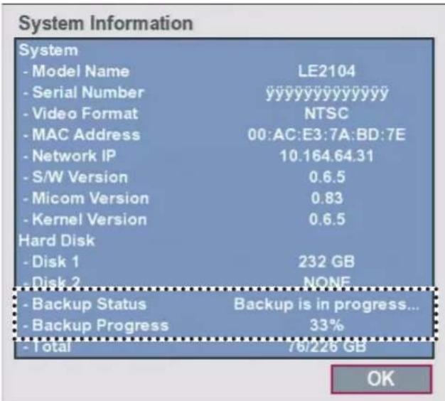
Notes:
• You cannot stop the backup in backup progress.
- The warning message will appear for the conditions listed below.
- When the start time and end time are the same value.
- When the start time is later than the end time.
- A media has not enough space.
- When you set the time for data that does not exist.
- The disc burning is carried out by a single session closed format.
• If you use the CD/DVD writer device for backup, the backup status will be displayed as shown below.
- 1st. Status of making ISO image

- 2nd. Status of writing

Daily/Weekly backup
- Connect the USB device for backup. You cannot use the CD or DVD writer for daily or weekly backup.
- Select [WEEKLY] or [DAILY] on the schedule options.
- Select the backup device.
- Enter the date and/or time to start backup on the schedule start option.
- Enter the day of week and/or time on the Time Range Start option.
- Enter the day of week and/or time on the Time Range End option.
- Select [Estimate] icon and press ENTER.
- Check the size of selected data and free space of USB device. If the USB device has not enough space, change the USB device of enough space or erase the connected USB device.
Notes:
• You cannot stop the backup in backup progress.
- The warning message will appear for the conditions listed below.
- When the start time and end time setting are wrong.
- A media does not have enough space.
- When you set the time for data that does not exist.
-
When the selected USB device is disconnected.
-
The estimated size of backup data is only the approximate size. So you must prepare sufficient space on the media to prevent lack of space.
- When the backup process starts, you can check the backup status on the system information window.
- While export is in progress or searching the backup data from the external USB device, the scheduled backup will not be started. After the export or backup search is finished, scheduled backup will be restarted.
- When you set the schedule backup, the backup data size is estimated from the recording settings of the Setup menu. If the real recorded data size are over the estimated recording data size, the schedule backup may not be activated.
System
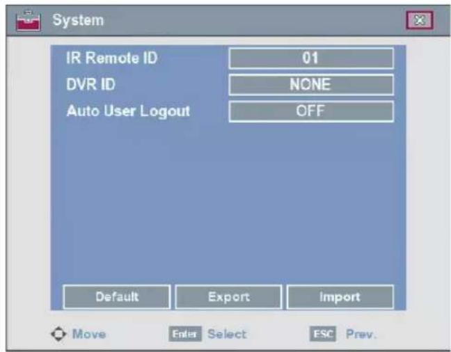
- IR Remote ID: Select the IR Remote ID for this unit (01 to 09). If you use multi systems set the IR Remote ID for each DVR unit.
- DVR ID: Select the DVR ID for this unit (NONE, 01 to 16). If you use multi systems set the DVR ID for each DVR unit. You can control the DVR by using the LKD1000 controller. (For more details refer to the LKD1000 owner's manual.)
- Auto User Logout: Logout is automatically at fixed intervals. You can set auto logout time to 5 MIN, 10 MIN, 30 MIN, 60 MIN or OFF.
- Default: You can reset the DVR to its original factory settings. Some options cannot be reset (date, time, daylight saving, time zone and user password settings).
- Export: Export the configuration data from this DVR to the USB memory stick.
- Import: Import the DVRs configuration data from the USB memory stick.
Notes:
- Configuration data import is available when the configuration data of a DVR is the same kind as this unit's data.
- If you use a USB memory stick for configuration export, you must disconnect the other external USB devices.
Recording
Images from a camera will be recorded on the built-in hard disk.
Note:
External recording devices can be used as copy areas for images recorded on the hard disk. It is impossible to record images on the external recording devices directly.
Instant recording
Ensure all the cameras are connected and that time and date have been set correctly. Before you start recording, first check the repeat recording settings in the recording menu of the system setup, and then make the recording settings.
- Press the REC button and then press the channel button you want to record. The recording type indicator turns green "I" on the selected channel screen of the main monitor.
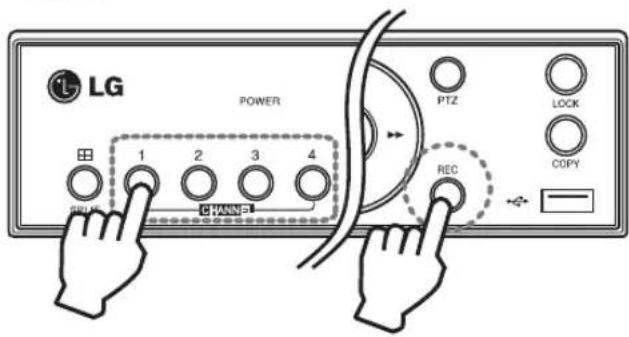
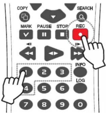
- Press the REC button and then press the channel button you want to stop recording. If you stop instant recording, the recording mode will be changed into the scheduled recording mode (Continuous/ Alarm/ Motion records). If the schedule is not set, the button indicator turns off and the recording type indicator turns white "N" on the selected channel screen of the main monitor.
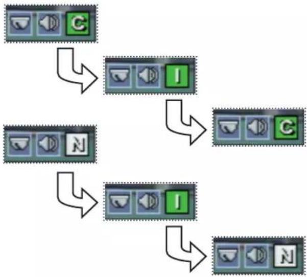
flowchart
graph TD
    A["Green C icon"] --> B["I green square icon"]
    B --> C["C green square icon"]
    C --> D["I green square icon"]
    D --> E["N green square icon"]
Notes:
- You can instant record that the channels scheduled such as alarm, motion or continuous.
-
Once you stop instant recording, the recording type indicator will be changed to the scheduled recording mode.
• You can not record the Instant and Continuous recording in following conditions. -
A HDD is not attached.
- A HDD is not formatted.
- The channel has no video input for display.
- Overwrite sets to "OFF" or "EVENT PARTITION", and normal partition is full.
- On the HDD setting, the event partition is set to 100 %.
• You can not record the Sensor and Motion recording in following conditions.
- A HDD is not attached.
- A HDD is not formatted.
- The channel has no video input for display.
- Overwrite sets to "OFF" or "NORMAL PARTITION", and event partition is full.
- On the HDD setting, the event partition is set to 0 %.
- The schedule (Sensor/Motion) record is not set.
• HDD partition according to a recording type.
- Normal Partition: It is the space in the HDD that stores the continuous and instant recorded data. Once the normal partition is set to 0 % (the event partition is 100 %), you can not record the continuous or instant recordings.
- Event Partition: It is the space in the HDD that stores the alarm and motion recorded data. Once the event partition is set to 0 %, you can not record the alarm and motion recording.
• Priority of record.
Instant record > Sensor record > Motion record > Continuous record.
• You can not do instant recording with the mouse.
Search and Playback
Playback
It is possible to play a recorded image without stopping recording.
- Select a channel you want to playback.
- Press ◀▶ to play a recorded image of the previous 1 or 2 minutes of recording.
The playback image will be displayed on the full screen window.
- Press ■ (STOP) to stop the playback.
Search
The various search functions of this unit can be used to go to the beginning of the desired picture. This unit is equipped with 3 search functions.
When the SEARCH button is pressed the search menu is displayed.
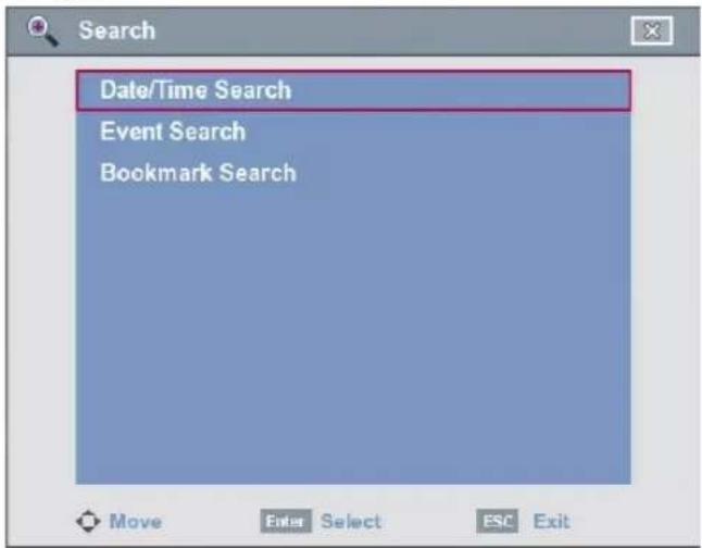
Date/Time Search
Use to search recorded pictures by specifying date and time.
- Use ▲/▼ to select the [Date/Time Search] option then press ENTER.
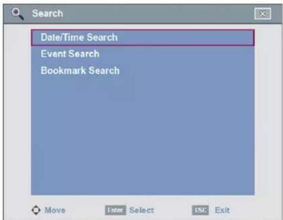
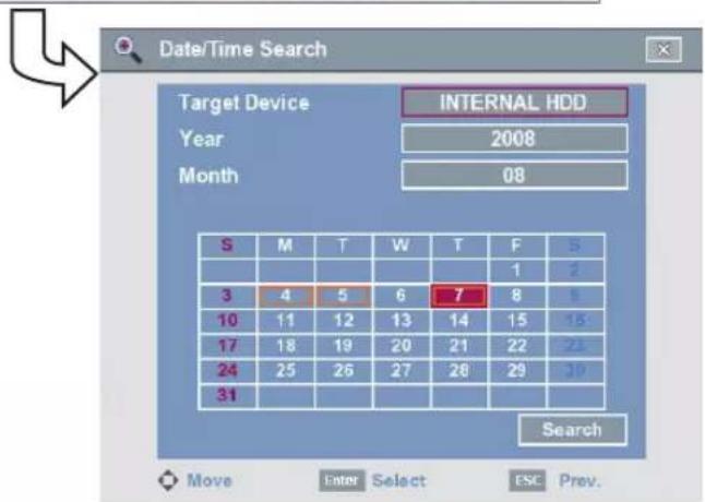
- Select [Target Device] then press ENTER.
- Use ◀/▶ to select the desired source device.
• INTERNAL HDD: Plays back or searches recorded contents of the internal HDD device.
• Source Device: Plays back or searches backup contents of the source device.
- Press ENTER to confirm it.
- Select year or month option then press ENTER.
- Use ◀/▶ to input the year or month.
- Press ENTER to confirm it.
- Use ◀/▶/▲/▼ to select the day then press ENTER.
- Select the [Search] icon then press ENTER. The search result is displayed.
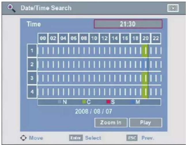
- Use ▲/▼ to select the channel you want to playback and press ENTER. Repeat this step to select the other channels.
- Select the [Time] option and select the start time of the recorded image to playback.
- Press ◀▶ (PLAY) or click the [Play] icon to start playback. The picture(s) is (are) displayed in the main monitor.
- Press STOP (■) to stop playback and return to the previous menu.
- Press SETUP/ESC repeatedly to exit the search menu.
Notes:
- Recorded data shown on the time graph will be displayed in different colors depending on the recording type.
- Green: Continuous recording.
- Red: Sensor recording.
- Blue: Motion-detection recording.
- No color: No recording.
- Select [Zoom In] option and press ENTER to view the detailed time by 6 hour intervals. Select the [Zoom Out] option to return to the normal time.
Event Search
Search a recorded picture by date and type of event.
- Use ▲/▼ to select the [Event Search] option then press ENTER. The event search menu is displayed.
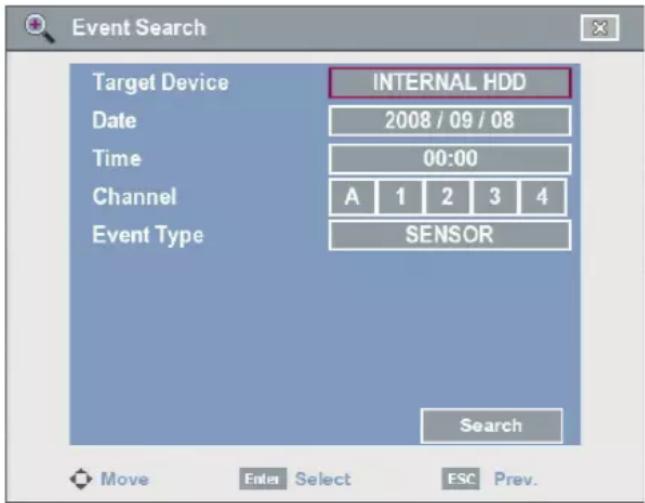
- Select [Target Device] then press ENTER.
- Use ◀/▶ to select the desired source device.
- Press ENTER to confirm it.
- Select [Date] option then press ENTER.
- Set the year, month or day.
6-1. Use ◀/▶ to select a column and press ENTER.
6-2. Use ◀/▶ to select the year, month or day.
6-3. Press ENTER to confirm it.
6-4. Select [OK] and press ENTER to confirm the settings and exit the date setup menu.
- Select [Time] option then press ENTER.
- Set the time.
8-1. Use ◀/▶ to select a column and press ENTER.
8-2. Use ◀/▶ to select the hours or minutes.
8-3. Press ENTER to confirm it.
8-4. Select [OK] and press ENTER to confirm the settings and exit the time setup menu.
-
Select the channel for event search using ENTER. If you select [A], all channels are selected.
-
Use ▲/▼ to select the [Event Type] then press ENTER.
- Use ◀/▶ to select the event type then press ENTER.
- Select the [Search] icon then press ENTER. The event list menu appears.
- Select the recording data on the event list then press ◀▶ (PLAY) or select the [Play] icon then press ENTER to start playback. The picture is displayed in the main monitor.
- Press STOP (■) to stop playback and return to the event list menu.
- Press SETUP/ESC repeatedly to exit the search menu.
Bookmark Search
Search the desired picture with a bookmark registered by the bookmark function.
- Use ▲/▼ to select [Bookmark Search] then press ENTER.
The bookmark list menu is displayed.
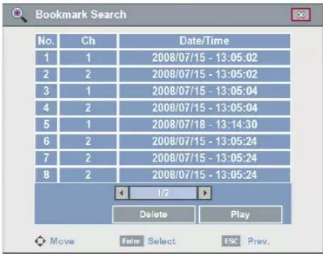
- Select the recording data on the list then press ◀▶ (PLAY) or select the [Play] icon then press ENTER to start playback. The picture is displayed in the main monitor.
Note:
If you delete the bookmark on the list, select the [Delete] icon then press ENTER.
- Press STOP (■) to stop playback and return to the bookmark list menu.
- Press SETUP/ESC repeatedly to exit the search menu.
Notes:
- Backup data can not be played back by a bookmark search.
- You can register a bookmark in the multi channel playback.
- If the storage spaces for bookmark is in full, you can not register a bookmark. You can register a bookmark after deleting the previously stored bookmark on the list.
Functions available during playback
| Button | Function | ||
| System Control Bar | Remote Control | Front panel | |
 |  |  | Stop playback. |
| Pause playback. | |||
 |  |  | Press repeatedly to select the required scan speed.(▶▶,▶▶▶,▶▶▶▶,▶▶▶▶▶ or ◀◀, ◀◀◀, ◀◀◀◀, ◀◀◀◀◀) |
| [SC5W] |  |  | Press repeatedly to play frame-by-frame in pause mode. |
 |  |  | Press to play reverse or normal playback. |
 |  | - | Press MARK at a desired point to be marked during playback. Up to 15 points can be marked. |
Notes:
- You can playback the backup or export data in normal speed only.
- If you use the reverse frame skip function, a frame may be skipped.
- Multi channel play works only in the date/time search function.
- During the multiple channel palyback, just one specific channel cannot be played on a full screen.
LG Network Client Program
Introduction
The LG Network Client program is an IP-Surveillance software that works with the LG DVR to provide video monitoring, recording setting and event management functions. The software has multiple search functions for recorded events. Remote viewing and playback are also possible with the use of the LG Network Client.
This manual contains instructions on how to use and manage the LG Network Client in your networking environment. Some knowledge of networking environments would be beneficial to the reader.
Should you require any technical assistance, please contact authorized service center.
Recommended PC Requirements
The LG Network Client program must be installed below operating systems for best performance and stability.
| Items Requirements | |
| Operating System | Windows XP Professional Service Pack 2 or above |
| CPU Intel Pentium IV or above | |
| Web Browser | Microsoft Internet Explorer 6.0 or above |
| Memory 1 GB | or above RAM |
| Graphics Card | 128 MB or above Video RAM (Use latest graphics card driver.) |
| Resolution | 1024 x 768 (with 32 bit color) or above |
| Network 100 | Megabit Network (Gigabit Network recommended for larger systems) |
Before install the program
- The description pictures may differ from your OS (Operating System) or Web Browser type.
- The pictures used in this manual are based on Windows XP Professional.
- Do not use other applications with this program. This can cause memory shortage and program malfunction.
- Check that the LG DVR is(are) connected to the network and that power is supplied.
Getting Started
Install the LG Network Client on your PC
You can install the LG Network Client software following steps.
- Insert the Client Program CD which will be started automatically. If the disc does not run automatically on your PC, open the Client Program CD and install the program manually.
- Run the install file and install the programs to your computer following the on-screen instructions. The [LG Emergency Agent] and [LG Export viewer] programs will be installed with the LG Network Client program installation.
- After finishing installation, you will find the programs in the Start menu or on the desktop.
Starting the LG Network Client
- Run the LG Network Client program. To launch LG Network Client, select LG Network Client from your Start > Programs > LG Electronics > LG Network Client > LG Network Client or click the LG Network Client icon on your desktop. The client password input window is displayed.
- Enter the password. (Note that the default client password are "000000".)
- Click the [OK] button and then the LG Network Client window is displayed.
Note:
If you mark up the [Auto Connection] option, the LG Network Client program is connected automatically at the next time.
LG Network Client Overview
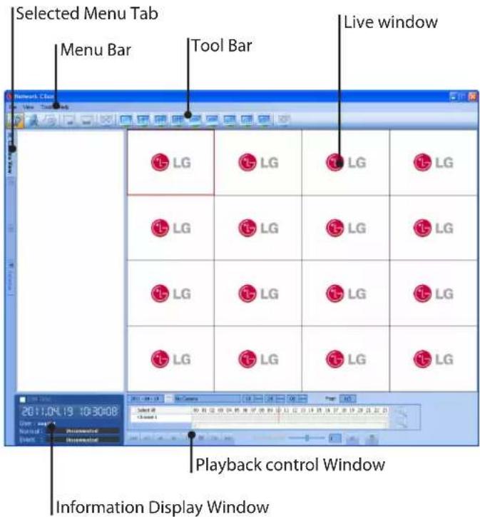
Menu Bar
| Menu | Sub-Menu | Description |
| File Client Password | You can change the password of the Network Client program.1. Select this option. The Client Password Setup window is displayed.2. Enter the password.3. Click [OK] to confirm your settings. | |
| Save to JPEG You can capture and save the current image in JPEG file format.1. Play the recorded data.2. Pause the playback at a desired point during playback.3. Select this option. The JPEG Export window is displayed.4. Set the options.5. Click the [Save] button. | ||
| Backup Search This menu is not used. | ||
| End Backup Search This menu is not used. | ||
| Software Update Use to upgrade DVR software or add/upgrade PTZ protocols.1. Log-in the Network Client Program as the Administrator authority.2. Click this option. The Update setting window is displayed.3. Select the update device from the list.Select All: If you click this button, the all devices in the list are selected.Clear All: If you click this button, the all selected devices in the list are deselected.4. Find and open the update file.5. Click the [Update] button to begin the update process. The DVR will be restarted after updating.6. Click the [Exit] button. | ||
| Exit Exit the program. | ||
| View OSD | · Channel Number: Displays or removes the channel number in the channel window.· Site Name: Displays or removes the site name in the channel window.· Camera Name: Displays or removes the camera name in the channel window.· Playback Time: Displays or removes the date/time of playback data in the channel window.· PTZ: Displays PTZ camera icon in the channel window.· Audio: Displays audio icon in the channel window.· Select All: Displays all OSD options in the channel window. | |
| Sequence (Dwell Time) | Select the sequence to 5 seconds, 10 seconds, 15 seconds or 20 seconds. | |
| Sequence Mode | · Channel Sequence: Each channel of the selected site in the sequence mode will be displayed in sequence.· Site Sequence: Each channel of the logged site in the sequence mode will be displayed in sequence. | |
| Language | Select the language for LG Network Client program. | |
| Resolution | Select the resolution of the LG Network Client program. | |
| Tools Connection Information | Displays the Connection List windows. Add, Edit or Delete the site name or group name in LG Network Client. | |
| This menu is not used. | ||
| Help Client Information | Displays Network Client Version Information. | |
Tool Bar
| Icon Description | |
 Live Live | Displays the live view workspace.·Camera View: You can see the surveillance camera's images in the window(s) and the camera information.·Pan/Tilt/Zoom: You can control the PTZ camera.·Log View: You can see the system log list.·Favorites: You can save the current configuration of the camera view. And, it is possible to return to a previous configuration of the camera view. |
 Search Search | Displays the search workspace. You can search and play the recorded data using the search functions. |
 Setup Setup | You can set the configuration of the selected site via the network. |
 Export Export | Displays the Export pop-up windows. |
 Print Print | When you click the PAUSE button to pause the playing the recorded data of the selected channel, the Print Icon is activated. You can print the paused picture of the recorded data of the selected channel. |
 Full Screen Full Screen | You can view the live window in full screen mode. To return to the normal screen, click the right mouse button. |
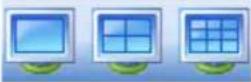   Division Division | When the icon is clicked, the screen will be changed to split mode and if the icon is clicked again, the screen will be changed by sequence (except 36 split mode). Choose the screen division mode. |
 Sequence Sequence | View all the channels in sequence. You cannot use sequence mode with the 36 split. |
Information Display Window
Displays current date and time, user ID and the remaining HDD status.
Note:
The DVR Time option is not activated for LE2104 Series models.
Playback control Window
You can playback the recorded data of the selected channel.
Operation and settings
Register the Site Name or Group Name
The first time LG Network Client is started, you should register a site name to control it by the LG Network Client program. The computer running LG Network Client program must be on the same network with DVR.
- Select [Tools] > [Connection Information] option on the menu bar. The Connection List window is displayed.
- After completing the settings, click the [OK] button to confirm the settings and exit the window. The registered site or group name is(are) displayed on the [Camera View] tab window.
Create a new group name
- Click the [Add Group] button. The Add Group window is displayed.
- Enter the group name.
- Click the [OK] button to confirm it. The registered group name is displayed on the Connection List.
Edit a group name
- Select the required group name on the Connection List.
- Click the [Edit] button. The Edit Group window is displayed.
- Overwrite the existing group name with a new name that you want.
- Click the [OK] button to confirm it.
Delete a group folder
- Select the required group name on the Connection List.
- Click the [Delete] button. The selected group name is deleted. Deleting a group name will delete all site names within the group name as well.
Add the Site Name
- Click the [Add] button. The Connection Setup window is displayed.
- Select the group name from the drop-down list.
- Enter the description of the site name.
- Enter the IP Address or the Host Name that you entered in the DDNS setup menu of the DVR. In case of entering the server name instead of the IP Address. You should set up the DDNS configuration properly in the server. Please refer to the server manual to set up the DDNS function.
| Case How to find the IP Address | |
| Using the Static IP Address | Check the IP Address in the TCP/IP option of the DVR setup menu. |
| Using the Dynamic IP Address | You have to activate the DHCP function.1. Press INFO to display the System Information window.2. Check the “Network IP” options value. |
| Using the DDNS function | Check the registered Host Name of the DDNS setup menu. |
| The DVR is connected to the network through the Broadband Router | You must set the port forwarding according to the settings of the broadband router. Refer to the manual of Broadband router for more detailed settings. If you use the multi DVR with Broadband router, you must set the TCP/IP port number for each DVR. |
-
Enter the TCP/IP port number of the DVR. If it isn't entered, the port number is set by default.
-
Enter the User ID and Password. If you set the User ID and Password, you can use the Auto connection function.
-
Click the [OK] button. The registered site name is displayed on the Connection List.
Edit the Site Name
- Select the required site name on the Connection List.
- Click the [Edit] button. The Connection Setup window is displayed.
- Specify the Group Name, IP Address, Port, User ID, Password and click the [OK] button to confirm the settings. You cannot edit the site name option.
Delete the Site Name
- Select the required site name on the Connection List.
- Click the [Delete] button. The selected site name is deleted.
Connect to the DVR
- Select the registered site name to connect it.
- Click the right mouse button on the site name. Select the [Connect] option. The site name is connected automatically and the site name is activated. If the site name has no information of the User ID and/or Password, the remote login window is displayed. In that case, enter the User ID and the password.
About the pop-up menu
- User Log-In: Select to connect the DVR manually.
- User Log-Out: Select to disconnect the site name.
- Connect: Select to connect to the DVR automatically. You should set the User ID and Password option of the connection information setting menu for using this function.
-
Disconnect: Select to disconnect to the site name.
-
Repeat step 1 to 2 to connect the other site name.
Notes:
- If someone logged in the DVR using the Admin ID, you can not log-in using the Admin ID.
- If you want to log-out, right click the mouse on the site name and select [User Log-Out].
- Up to 5 users can connect to the DVR system using the client program as shown below.
| User User 1 User2 | User3 User4 User5 | ||
| Case 1 Admin Power Normal | Normal Normal | ||
| Case 2 Power Power Normal | Normal Normal | ||
| Case 3 Normal Normal | Normal Normal | ||
| Case 4 Admin Normal | Normal Normal | ||
| Case 5 Power | Normal Normal | Normal Normal |
Connect the group device
- Select the registered group name to connect it.
- Click the right mouse button on the group name. Select the [Connect] option. Each site name is connected automatically and the site name is activated in the group name.
- Repeat step 1 to 2 to connect the other group name.
Disconnect the site name or group name
- Select the required site name or group name.
- Click the right mouse button on the site name or group name. Select the [Disconnect] option. The site name is disconnected and deactivated.
- Repeat step 1 to 2 for disconnection.
Using the Live function
Camera View Tab
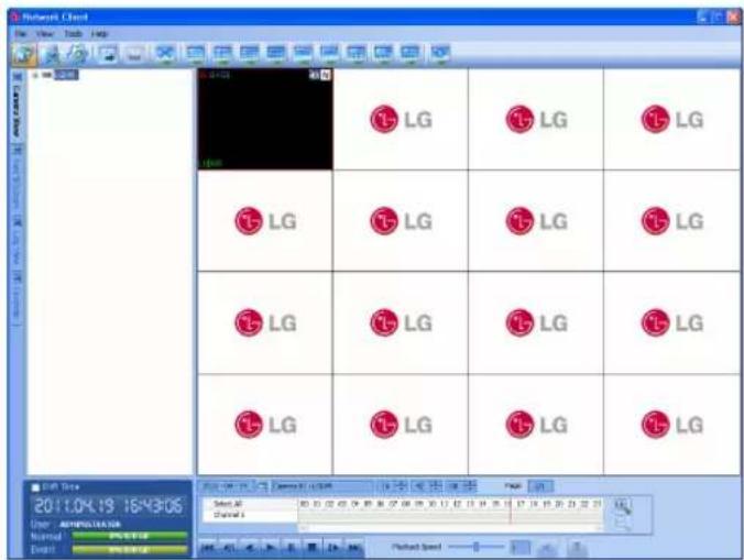
- Select the [Camera View] tab in the live mode.
- Select the activated site name and double click the left mouse button or click the plus mark of the registered site name.
- Select [Cameras] and double click the left mouse button or click the plus mark.
- Select the channel number you want to view.
- Click the channel number and drag and drop to live
window position. If you select [Cameras] and drag and drop to a live window then all channels are displayed.
-
Live image is displayed in the selected window.
-
Repeat steps 3 to 5 to set the other live windows.
Note:
- Configuration of camera view is set the first time only. This configuration setup is memorized for the next time and displayed as it is.
• About the camera view menu tree.
| [87, (A377) LG DVR | Displays the registered site name or group name. | |
| Cameras | Displays the camera information. | |
| CH 01 | Displays the camera channel name. | |
| 352 x 240 | Displays the Resolution. | |
| 30 FPS | Displays the Recording Frame Rate. | |
| Standard | Displays the Quality. | |
| Continuous | Displays the Recording mode. | |
| None | Displays the relay output condition. | |
| Audio 01 | Displays the Audio information. | |
| Sensor In | Displays the Sensor In information. | |
| Sensor In 01 | Displays the ON/OFF condition of the connected sensor. | |
| Sensor In 01 Relay Output 03 | Displays the relay output condition for the selected sensor input. | |
| Sensor In 02 CH 02 | Displays the camera condition for the selected sensor input. | |
| Relay output | Displays the Relay output information. | |
Instant playback
It is possible to play a recorded image without stopping recording.
- Select the [Camera View] tab in the live mode.
- Select a channel you want to playback.
- Select the date.
The day is displayed in a blue text when recorded data exists.
- Select playback start time.
When using timeline to search a start time, use the zoom in/out icons for more detailed searches (4 step).
-
Select playback speed. Use the slider to select the playback speed.
-
Start playback using these control buttons.
| Click this button to jump to the beginning of the data. | |
| Click this button repeatedly to play frame-by-frame playback in reverse. | |
| Click this button to play reverse or normal playback. | |
| Click this button to pause playback. | |
| Click this button to stop playback. | |
| Click this button repeatedly to play frame-by-frame playback. | |
| Click this button to jump to the last 1 minute of the data. | |
| This button is not used. | |
| This button is not used. |
Note:
You can not use the playback function when you log in with the Normal User ID.
Pan/Tilt/Zoom Tab
You can control the PTZ cameras via the network.
- Select the PTZ camera channel window in the camera view mode.
- Select the Pan/Tilt/Zoom tab.
- Use virtual remote control buttons to control the PTZ camera.
Note:
- If someone is controlling a PTZ camera using the DVR, you cannot use the PTZ function and vice versa.
- This function is permitted for Administrator group and other group users who have the PTZ authority.
| Button Function | |
| Use to pan/tilt the camera. |
| Confirm the preset position. | |
| To adjust the camera zoom. | |
| To manually adjust the focus of a camera. | |
| To manually adjust the iris of a camera. | |
| PRESET 000 | Displays the Selected Preset number. |
| To input the preset number. | |
| To register preset positions. | |
| To move the camera to the preset position. | |
| To delete a memorized preset position. | |
| To start a preset tour. | |
| To display the setup menu of the PTZ camera. |
Preset Settings
Preset position is the function to register camera monitoring positions (preset positions) associated with position numbers.
By entering the position numbers, you can move cameras to the preset positions.
Note:
To activate this function, you need to register the preset positions of the PTZ cameras.
To Register Preset Positions
- Move the camera to a point you wish.
- Click the [SET] icon.
- Select the preset number you wish to register.
- Click the icon.
The position and its number are memorized.
- Repeat steps 1 to 4 to add additional positions.
Note:
Preset numbers from 0 to 255 are available on this unit but the actual preset range differs depending on PTZ cameras.
Changing to a Picture in a Preset Position
The following function is available only with cameras provided with the preset function. The preset function makes the combination camera move to the programmed preset position. It is necessary to program preset positions for the combination camera beforehand.
- Click the [MOVE] icon.
- Use number buttons to enter the memorized preset position's index number then click the icon. The camera moves to the preset position and the picture of the camera in that position appears on the monitor.
To Clear the Preset Position
You can clear a memorized preset position.
- Click the [CLEAR] icon.
- Use number buttons to enter the memorized preset index number then click the icon to clear the preset positions.
Note:
This function may not be available depending on PTZ cameras.
To Tour The Preset Positions
You can tour all preset positions.
- Click the [TOUR] icon.
All registered preset positions in the camera will be selected and the camera position image will be switched on the active monitor. - You can stop the tour by clicking the [TOUR] icon.
Setup for PTZ Cameras
You can adapt the camera to your requirements by setting up the respective items in menus.
- Click the [SETUP] icon.
The setup menu appears in the selected window. - Use arrow and buttons to set the options.
Note:
• Refer to the manuals of the PTZ camera for more details.
- Some PTZ cameras may not be operated correctly with this program.
Log View Tab
You can see the system log list of selected site name.
- Select the [Log View] tab.
- Click the icon and select the day. (The selectable days are displayed in blue color.)
- Click the icon. The system log is displayed in the list.
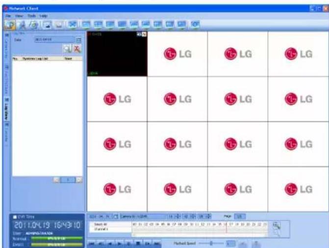
Favorites Tab
You can save the current configuration of camera view.
This favorite setup is useful for the next time to display it.
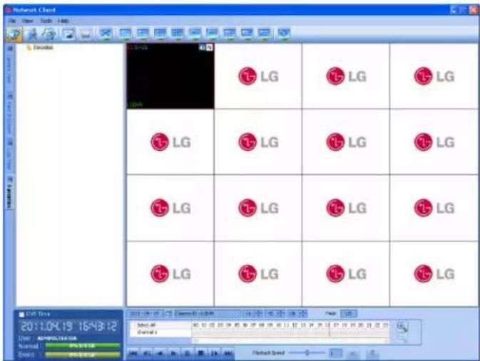
Add the favorite
- Select the [Favorites] tab.
- Select the [Favorites] option and click the right mouse button.
- Select the [Add favorite] option. The Add Favorite window is displayed.
- Enter the favorite name and click the [OK] button. The entered favorite name is displayed under the Favorites option.
Edit the favorite
- Select the registered favorite name and click the right mouse button.
- Select the [Edit Favorite] option. The Edit Favorite window is displayed.
- Overwrite the existing name with a new name.
- Click the [OK] button to confirm it.
Delete the favorite
- Select the registered favorite name and click the right mouse button.
- Select the [Delete Favorite] option. The selected favorite name is deleted.
Using the Search function
Date/Time Search Tab
Use to search a recorded picture by specifying date, hour and minute.
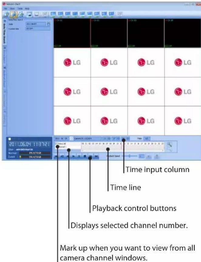
- Select the [Date/Time Search] tab.
- Click the icon and select the day. (The selectable days are displayed in blue color.)
- Select the channel window you want to view.
- Select the time using the Time line and Time input column to search recorded data.
- Play the searched data using the playback control buttons.
Event Search Tab
Search a recorded picture by date and event type.
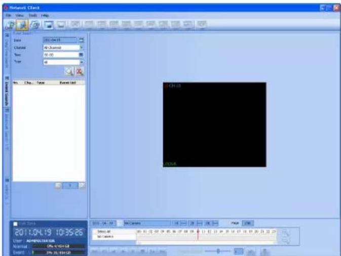
- Select the [Event Search] tab.
- Click the icon and select the day. (The selectable days are displayed in blue color.)
- Select the camera channel for event search.
- Select the start time.
- Select the event type.
- Click the icon. The event list is displayed.
- Select the event from the event list.
- You can play the searched data using the playback control buttons.
Bookmark Search
Search the desired picture with a registered bookmark using the bookmark function.
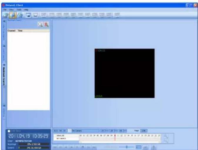
- Select the [Bookmark Search] tab.
- Click the icon. All bookmark data is displayed in the list.
- Select the data in the list.
- Play the searched data using the playback control buttons.
Using the Remote Setup function
You can set the DVR configuration of a selected site name using this function.
Camera / Display Setup
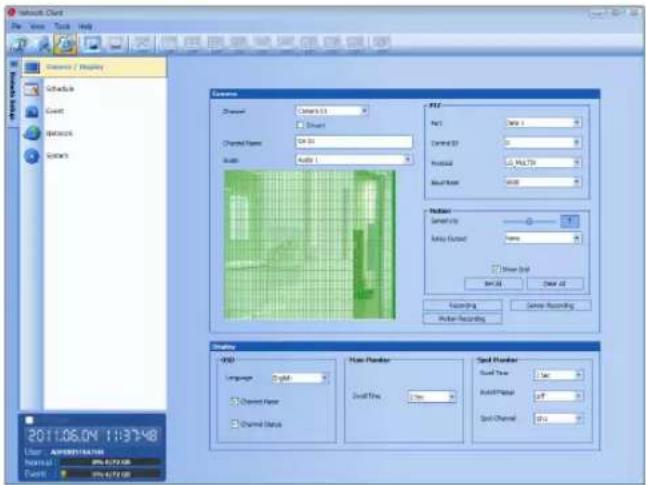
Camera Setting
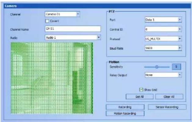
- Select a channel for settings. If you want to block a channel from other users, mark up the convert option. The marked up channels are displayed "LG logo" on the live windows for POWER or NORMAL user.
- Enter the new channel name.
- Select input audio channel.
-
Set the PTZ control options.
-
Port: Select the connected data port of the RS-485 terminal on the rear panel.
• Control ID: Select the PTZ camera ID from 0 to 255. Make the same settings as the PTZ camera. -
Protocol: Select the protocol supported by PTZ camera.
• Baud Rate: Select the communication speed. (1 200, 2 400, 4 800, 9 600 or 19 200) -
Set the motion options.
- Sensitivity: Set the sensitivity level for the created motion detection area. Sensitivity can be set from 0 to 10.
- Relay Output: Select the number of the ALARM-OUT terminal for the output alarm signal when motion is detected.
-
Area: The factory default of the Motion detection area is set as the whole area. You can change the area by using mouse on the preview window screen.
-
Select area: Click one point with the left mouse button and drag & drop to the end point.
- Clear area : Click the start point with the right mouse button and drag & drop to the end point.
Notes:
- If you want to display the grid, mark up the [Show Grid] option.
- If you want to select the entire area, click the [Set All] button or click the [Clear All] button to cancel the selected area.
Recording Settings
- Click the [Recording] button.
The recording setting window appears.
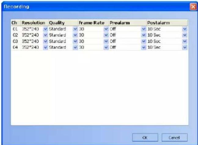
- Set each option using the mouse (See page 24).
- Click the [OK] button to confirm the settings.
Sensor Recording Settings
- Click the [Sensor Recording] button.
The sensor recording setting window appears.
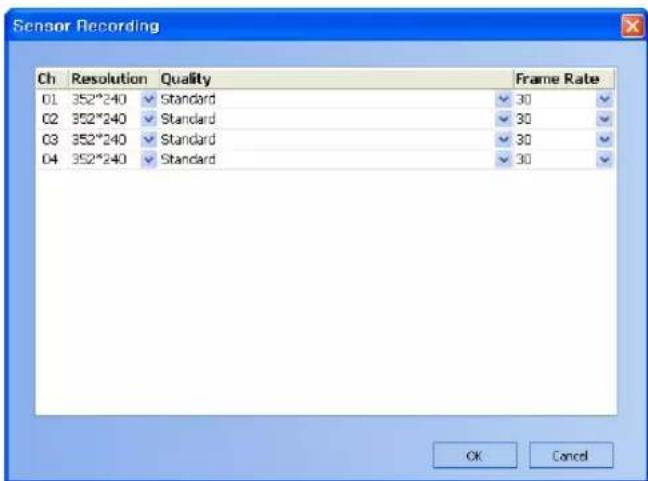
- Set each option using the mouse (see page 25).
- Click the [OK] button to confirm the settings.
Motion Recording Settings
- Click the [Motion Recording] button.
The motion recording setting window appears.
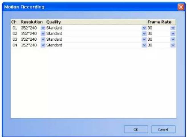
- Set each option using the mouse (see page 25).
- Click the [OK] button to confirm the settings.
Display Settings
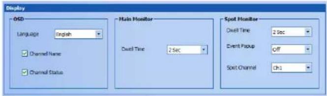
- Set the OSD options.
- Set the main monitor option.
- Set the spot monitor options.
Schedule setup
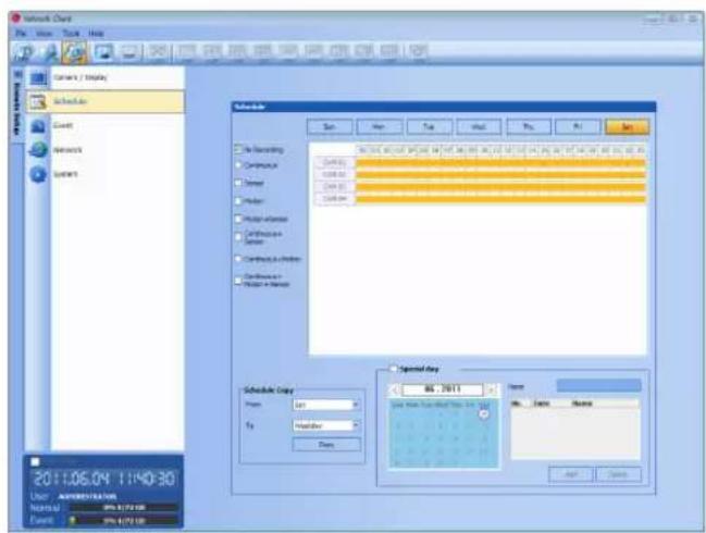
- Select a day of the week.
- Mark up the desired recording option.
• No recording: Do not schedule recording.
• Continuous: Recording starts automatically at the preset time.
- Sensor: Recording starts automatically when sensor occurs within a designated time.
• Motion: Recording starts automatically when motion is detected within a designated time.
- Motion+Sensor: Recording starts automatically when sensor and motion detection occur within a designated time.
- Continuous+Sensor: Recording starts automatically from the preset time. When the sensor alarm occurs within a designated time, change the continuous recording mode to sensor event recording mode and recording starts automatically.
- Continuous+Motion: Recording starts automatically from the preset time. When the motion is detected within a designated time, change the continuous recording mode to motion event recording mode and recording starts automatically.
- Continuous+Motion +Sensor: Recording starts automatically from the preset time. When the sensor alarm signal has input or motion has been detected, change the continuous recording mode to motion event recording mode and recording starts automatically.
-
Select the channel to set the schedule.
-
Click the start time cell block and drag & drop to select a time period cell block.
or
Click the start time cell block of a channel and drag & drop across the channels to select the time period block for multi-channel setting at the same time.
The color of the cell blocks will change.
Schedule Copy Settings
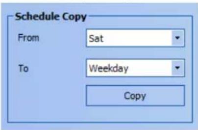
- Select the source day to copy.
- Select the destination day from the day of the week, weekday or weekend options.
- Click the copy button to copy the schedule data.
Special day Settings
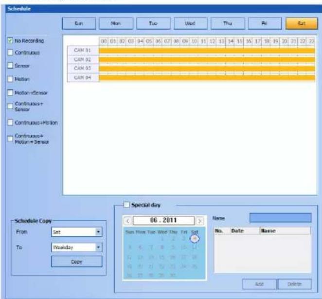
- Mark up the special day option.
- Select the date to set the special day schedule.
- Mark up the desired recording option.
-
Select the channel to set the schedule.
-
Click the start time cell block and drag & drop to select a time period cell block.
or Click the start time cell block of a channel and drag & drop across the channels to select the time period block for multi channel setting at the same time. The color of the cell block will change.
-
Enter the name of the special day.
-
Click the add button to add the special day settings.
The special day is added to the list. If you want to cancel the registered special day, select the special day in the list and click the delete button.
Event setup
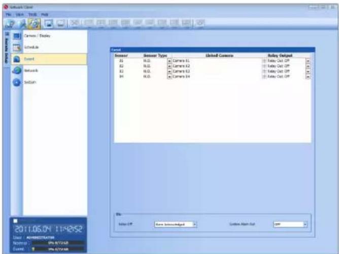
1. Set the event options.
- Sensor: Displays the number of the ALARM-IN terminal.
- Sensor Type: The alarm state can be set to either N.O. (Normally Open) or N.C. (Normally Closed).
- Linked Camera: Select the connected camera channel with the ALARM-IN terminal.
- Relay Output: Select the alarm output number of the ALARM-OUT terminal for the output alarm signal.
2. Setting [Etc] options.
- Relay Off: Set the "Alarm Acknowledged" or "Post Alarm Time" option to off.
• System Alarm Out:
- ON: Outputs the alarm (relay) signal via the ALARM-OUT terminal below cases.
When the HDD has bad sector.
When a video signal from the camera has stopped because of a cable disconnection or malfunction of a camera.
- OFF: Not used.
Network setup
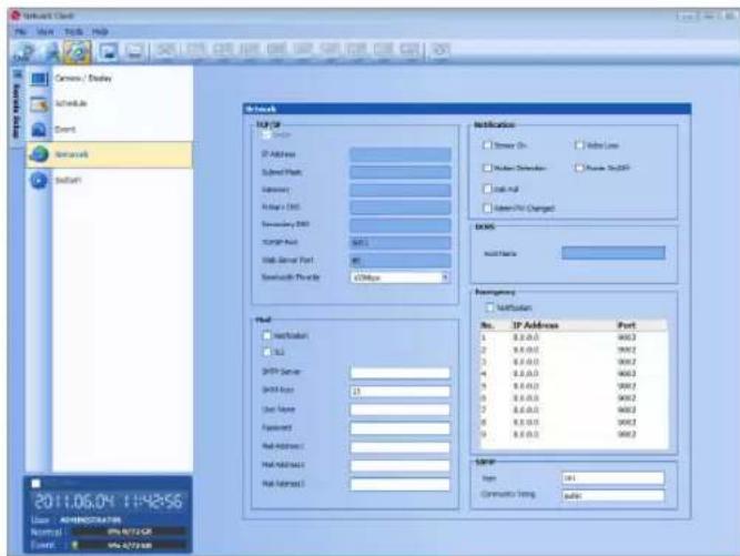
TCP/IP Settings
The [DHCP], [IP Address], [Subnet Mask], [Gateway], [Primary DNS], [Secondary DNS], [TCP/IP Port] and [Web Server Port] option settings are not available in the client program. You can set these options in the system menu of the DVR.
- Bandwidth Throttle: Selects the bandwidth to adjust the data traffic.
Mail Settings
Set the mail options.
- Notification: When you mark up the notification option, notify the user about unit operating information by E-mail according to your notification settings.
- TLS: Mark up when using the TLS (Transport Layer Security) function.
• SMTP Server: Enter the SMTP Server address. - SMTP Port: Enter the SMTP Port Number. Typically the TCP port used for SMTP is 25. However in some cases it is better to change this port number for added flexibility or security. If desired change the port number (1 to 65 535).
• User Name: Enter the user name.
• Password: Enter the password. - Mail Address (1 to 3): Enter the mail address.
You can input up to 3 E-mail addresses.
Note:
The [SMTP Server], [SMTP Port], [User Name] or [Password] settings are optional. The DVR can send e-mail directly without the use of an SMTP server or an MTA (message transfer agent). In certain cases all e-mail should be forwarded to a specific SMTP server. Specify the server host name or IP address in such cases. For more detail on SMTP setup, ask your network administrator and/or mail service provider.
Notification
Set the notification options.
- Sensor On: Sends an E-mail when a sensor has been detected.
• Video Loss: Sends an E-mail when a video signal from the camera has stopped because of a cable disconnection or malfunction of a camera.
• Motion Detection: Sends an E-mail when motion detection has occurred.
• Power On/Off: Sends an E-mail when power is on or off. - Disk Full: Sends an E-mail when the HDD has fully recorded.
- Admin PW Changed: Sends an E-mail when the administrator password has changed.
DDNS
• Host Name: The registered host name is displayed.
Emergency
- Notification: Notify the emergency agent about unit operating information according to your notification settings.
- IP Address, Port: Enter the IP Address and port number of the emergency agent program installed in the PC. The factory default port for this function is 9002. However in some cases it is better to change this port number for added flexibility or security. If desired change the port number (1025 to 65 535). You can set up to 9 IP address and port numbers.
SNMP
- Port: Enter the SNMP Port Number. Typically the port used for SNMP is 161. However in some cases it is better to change this port number for added flexibility or security. If desired change the port number from 1 to 65 535.
• Community String: Enter the Community name.
System setup
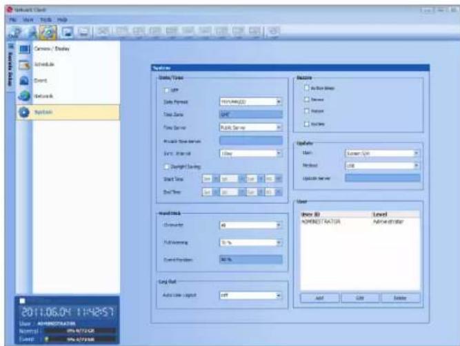
Date/Time settings
Set the date/time options.
- NTP: Mark up when using the NTP (Network Time Protocol) server for time adjustment.
• Date Format: Select the date display format. - Time Zone: This option setting is not available in the client program.
- Time Server: Select your time server. The DVR will obtain the average time among 5 public servers (time.nist.gov, time-a.nist.gov, time-b.nist.gov, ntp.nasa.gov, clock.isc.org).
- Private Time Server: Enter the private time server's IP address or host name.
- Sync. Interval: You can set synchronized interval with the NTP time server to 1 day, 1 hour, 1 week and 1 month.
- Daylight Saving: Mark up when you use the daylight saving function.
- Start Time: Select the Daylight Saving start time.
- End Time: Select the Daylight Saving end time.
Hard disk
• Overwrite: Select the overwrite recording type (Off, Normal Partition, Event Partition or All). This function is possible when the selected HDD type has fully recorded.
• Full Warning: When the HDD has overflowed the warning message is displayed.
• Event Partition: Sets the space of event partitions for event recording.
Log Out
- Auto User Logout: Setting the logout time. You can set the auto logout time to Off, 5 minutes, 10 minutes, 30 minutes or 60 minutes.
Buzzer settings
Select the buzzer options.
- Button Beep: Makes a sound when using the buttons.
• Sensor: Makes a sound when an sensor occurs.
• Motion: Makes a sound when motion is detected.
• System: Makes a sound when a HDD has bed sector.
Update settings
Set the update options.
• Item: Select the items for updating.
- PTZ Protocol: Set to PTZ Protocol update.
- System S/W: Set to System S/W update.
• Method: Select the update method.
- USB: Update from USB memory stick.
- Network: Update from the update server.
- Update Server: Enter the IP address of the update server.
Note:
If you can not update from the update server, check the TCP/IP options and the IP address of the update server.
User settings
Add the User
You can add the user.
- Click the "Add" button. User Setting window is displayed.
- Enter the User ID and Password.
- Enter the password again to verify.
- Select the user level and then click "OK" to confirm your selection.
Edit the registered User
You can change the User ID, password or user level.
- Choose the user ID and then click the "Edit" button.
- Change the ID, Password or User level then click "OK" to confirm your selection.
Delete the registered User
- Choose the user ID you want to delete
- Click the "Delete" button.
Using the Export function
You can copy the recorded images and audio data from the DVR unit to the PC. This function is permitted for Administrator and Power user.
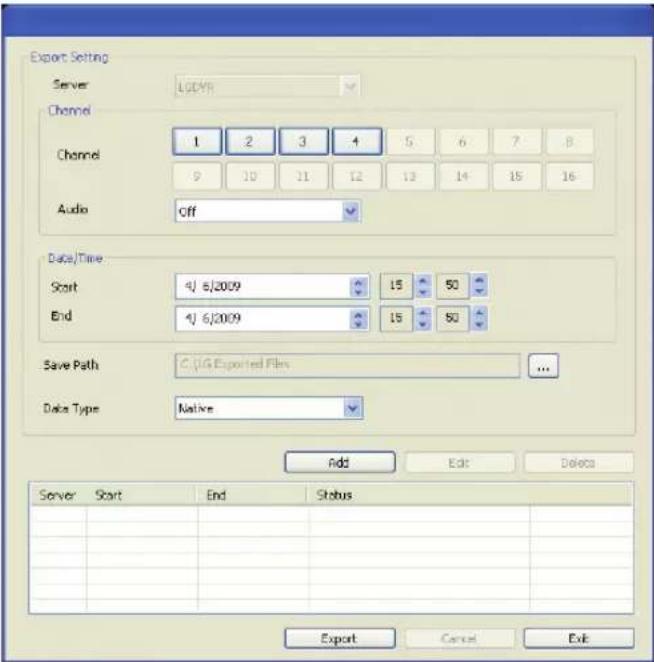
Export setting
• Server: Displays the selected server name.
- Channel
- Channel: Select a channel(s) to export the data. You should select more than one channel.
- Audio: Set to On or Off to export the audio data.
- Date / Time
- Start: Set the start date/time to copy.
-
End: Set the end date/time to copy.
-
Save Path: Displays the current exported data save folder. You can select (or make) the folder on the computer to save the exported data. The initial save folder is "C:\LE Exported Files". If you want to change the exported data save folder, click the icon and select the new folder.
- Data Type: You can select the saving file format between "Native [*.exp]" and "AVI". The Native file is saved with the extension of "*.exp" and the AVI file is saved with the extension of "*.avi". The saved "*.exp" file can playback using the Export Viewer program and "*.avi" file can playback using the Windows Media Player or the other ".avi" file player.
- Add: Add the export setting schedule to the list.
• Edit: Edit the selected export setting on the list. - Delete: Delete the selected export setting schedule from the list.
- Export: Click to start export the data of the selected export setting.
- Cancel: Click it to cancel data exporting.
- Exit: Click to exit the window.
How to export the data
- Set the Exprot Channel options. You should select more than one channel.
- Set the Date/Time options.
- Select the folder on the computer to save the exported data.
- Set the export saving capacity.
- Select the data type.
- Click [Add] button. Listing the configured server, start time, end time and Status.
- Select the registered export setting schedule in the list.
- Click the Export button to begin the export. The export status will be displayed on the Status column.
Note:
- The exported data file name is made automatically as the [Server name_Channel number_export start time.exp(or "avi")] type.
- If you do not assign the export directory, the export directory will be set to default directory and sub directory will be created with start date.
- If you log-out from the network client, the export sequence will be terminated.
- If you set the time for data that does not exist, the export function is not activated.
-
The warning message appears for the conditions listed below.
-
When the start date/time and end date/time are the same.
- When the start date/time is later than the end date/time.
Additional Programs
Emergency Agent Program
The system sends a message according to the Notification and Emergency settings in the event setup menu.
Emergency Agent Overview
![Display the received message list. Detailed view of the received message. Received Messages Subject [Event Report] 2010-02-02 19:10:47:346 (Motion Detected) [Event Report] 2010-02-02 19:10:36:274 (Motion Detected) [Event Report] 2010-02-02 19:09:335:599 (Motion Detected) [Event Report] 2010-02-02 19:09:219:933 (Motion Detected) [Event Report] 2010-02-02 19:09:103:50 (Motion Detected) [Event Report] 2010-02-02 19:09:52:546 (Motion Detected) [Event Report] 2010-02-02 19:08:096:56 (Motion Detected) [Event Report] 2010-02-02 19:08:08:232 (Motion Detected) [Event Report] 2010-02-02 19:06:57:253 (Motion Detected) [Event Report] 2010-02-02 19:06:51:835 (Motion Detected) [Event Report] 2010-02-02 19:06:35:821 (Motion Detected) From (10.19.220,28) Message: Event message received on Your DVR system! Event Time: 2010-02-02 19:09:00 Event Type: Motion Detected Camera Channel [OZ] Delete the selected message from the list. Closes the [Received Messages] window. Refreshes the received message on the list. Displays the search window. Displays the port change window.](/content/2026/05/956624/images/c1901f6edade2609c1206a3eae788a52fc9bad51b5630b6019ebb0fafdc69a97.jpg)
To activate the Emergency Agent program
- Run the [LG Emergency Agent] program. The Emergency icon is displayed in the system tray.
-
Whenever a notification function occurs, a message box is displayed on the bottom right of the screen. The message box is displayed for 5 seconds.
-
Check the message.
-
Click the message box within 5 seconds to display the [Received Messages] window.
or
Right click the mouse on the program icon in the system tray and select the [Check Message Box] option to display the [Received Messages] window.
-
You can check all the subjects of received messages.
-
Click the [CLOSE] button to close the [Received Messages] window.
Port Setting
- Click the [Setup] button. The option window is displayed.
- Enter the port number of the emergency agent listening port. The factory default port is 9002. However in some cases it is better to change this port number for added flexibility or security.
- Click the [OK] button to exit.
Message Search
-
Click the [SEARCH] button. The message search window is displayed.
-
Select the search method.
• Event Search: Search by selected type of event for the message.
• Date Search: Search by selected date.
- Click the [Search] button.
The search message is displayed on the [Received Messages] window.
Delete the Message from the List
- Select the message(s) you want to delete.
- Click the [DELETE] button. The confirmation window is displayed.
- Click the [Yes] button to delete the message(s).
Export Viewer Program
You can playback from the export data on the PC using this program. The export viewer program is saved automatically when you install the client program or export the data.
Export Viewer Overview
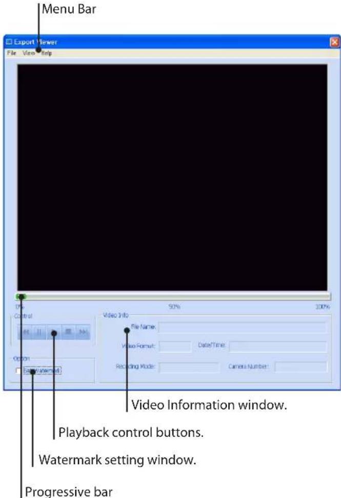
Menu Bar
| Menu Sub-Menu Description | |
| File Open | Open the data file. |
| Print Prints the current playback image. | |
| Save to JPEG You can capture and save the current image in JPEG file format.1. Play the recorded data.2. Pause the playback at a desired point during playback.3. Select this option. The JPEG Export window is displayed.4. Set the options.5. Click the [Save] button. | |
| Exit Exit the program. | |
| View Language Select the | language for Export Viewer program. |
| Video Size Select | the video size of the data file. |
| Help | About Export Viewer |
Playback control buttons
| Jumps to the beginning of the file. | |
| Pauses playback. | |
| Starts playback. | |
| Stops playback. | |
| Jumps to the end of the file. |
Watermark Setting window
The warning window will appear with watermark option, if the file which is in playback differs from the file that is originally recorded.
Video Information window
• File Name: Displays the file name.
• Video Format: Displays the video type of the data.
• Date/Time: Displays the recorded date and time of data.
• Recording Mode: Displays the save mode of the data.
• Camera Number: Displays the camera channel number of recorded data.
To play the exported data
- Run the LG Export Viewer program on the PC or in the Export Viewer folder of the external USB device. If you insert the exported data CD or DVD disc, the export viewer program run automatically.
- Select [File] > [Open]. The open window is displayed.
- Select the root directory of the USB device and search&select the desired file. An example of playable file format is "Channel name_date_time.exp".
- Click the [Open] button. The selected data is played back automatically.
- Click the [STOP] button to stop playback.
Progressive bar
You can search the image directly using the progressive bar. Click and hold the Slider bar and move to the other point you want and then release it. Or, Click the point on the progressive bar you want to playback.
Web Viewer Program
Logging in the Web Viewer
- Start the web browser. The recommended browser is Internet Explorer with Windows.
- In the Address Box, enter "HTTP://" and the IP Address of the DVR. You can use the Host Name that you entered in the DDNS setup menu of the DVR.
- Press the ENTER button on the keyboard and then the Web viewer and the Remote Login menu will be displayed.
- Enter the User Name and Password.
- Click the [OK] button.
Notes:
- If the Web Viewer is not displayed, check the TCP/IP settings of the DVR.
- If you connect the DVR for the first time, the Security Warning window is displayed. You must click [Install] on the Security Warning window to install the program for use the Web Viewer. If you click [Don't Install], the Web Viewer program is not available.
Web Viewer Overview
You can control the live image using the Web Viewer.
| Icon Description | |
| Live | Displays the live view workspace. • Camera View: You can see the surveillance camera's images in the window(s) and the camera information. • Pan/Tilt/Zoom: You can control the PTZ camera. |
| Search | Displays the search workspace. You can search and play the recorded data using the search functions. |
| Setup | Click to display the WebViewer Control Properties pop-up windows. |
| Click to display the Remote Export pop-up windows. | |
| You can view the live window in full screen mode. To return to the normal screen, click the right mouse button. | |
| Screen Mode selection icons. | |
 | View all the channels in sequence. You can use sequence mode with the one split only. |
 | You can capture and save the current image in JPEG file format. The initial save folder is “C:\LG Exported Files”. If you want to change the storage folder, set the [Save Path] option on the WebViewer Control Properties Window.1. Select the channel window.2. Mark up the selected channel name.3. Search the recorded data and then play the recorded data.4. Click this button when you want to capture the current image. |
Live screen control
- Left mouse button: Select the channel. If you want to set the 1 split mode, double click the selected channel. To return to the normal screen double click again.
- Right mouse button: If you want to exit the full screen mode, right click the mouse to return to the normal screen.
Using the WebViewer Control Properties window
- Click the [Setup] button.
WebViewer Control Properties window is displayed.
-
Set the below options.
-
OSD: Mark up to display or remove the selected option in the channel window.
• Sequence: Selects the channel sequence time.
• Video Display: Marks up when using the DirectX function. -
Snapshot Save Path: Displays the storage folder for the captured image file. If you want to change the storage folder, click the [...] button and select the new folder.
-
Click the [OK] button to exit.
Playback of Recorded Data
- Select the camera's display window.
- Select the date.
The day is displayed in a blue text when recorded data exists.
- Select playback start time.
When using timeline to search a start time, use the zoom in/out icons for more detailed searches (4 step). - Select the channel you want to playback. If you check "Select All" option, you can playback the all channels simultaneously from all camera channel windows.
- Select playback speed.
- Start playback using these control buttons.
Troubleshooting
Check the following guide for the possible cause of a problem before contacting service.
| Symptoms Resolutions | |
| The system power does not turn on. | Check the power cable is connected correctly. |
| Check the input voltage is correct. | |
| If the system power does not turn on even if the power cable is connected correctly, please contact the service center. | |
| The system power is turned on but no video data is displayed on the monitor. | Check the monitor power cable is connected properly. |
| Make sure the monitor is turned on. | |
| Check the video output cable of the LG DVR is properly connected to the monitor. | |
| Check the selected monitor type (see page 12). | |
| Unplug the power cable and plug in again. | |
| The camera numbers are displayed on the screen but the camera images are not displayed. | Check the camera video output is connected to the DVR system correctly. |
| Check the power cable on the camera is connected correctly. | |
| Check there is no problem with the video cable connection from the camera to the LG DVR system. | |
| Turn off the DVR system and turn it on again. | |
| The camera video is shown on the screen but the system does not record the video. | Check the recording mode in the record setting menu. |
| Check the HDD detection status in the System Information window.If the HDD detection status is abnormal, check the HDD formatting and the connection of the HDD. | |
| Check the recordable disk space in the HDD. | |
| Check the overwrite option in the setup menu for overwrite recording. | |
| It is impossible to search through the recorded video. | Check if there is recorded video data at the time that you are trying to search on the table. |
| If there is no recorded video data, check the recording mode in the record setting menu. | |
| Check the HDD detection status in the system information window.If the HDD detection status is abnormal, check the HDD formatting and the connection of the HDD. | |
| Check the user type. The search function is not available for a normal user. | |
| Audio data recorded with video data is not playing. | Check the audio recording option is correctly set for the camera you wish to record audio. |
| Check the speaker and audio (line input) on the rear of system are connected correctly. | |
| Check the connected speaker is working properly. | |
| The colors of some camera videos are strange or videos are displayed abnormally. | If the camera connected to the system has a problem, make sure that the camera is not damaged by trying another camera into a working video output. |
| Check the video format setting of the unit is the same as the connected camera's video format. Depending on your region, the camera's video format can support either PAL or NTSC. Depending on the camera's video format, the video process can differ greatly, therefore it can be difficult to recognize the video data if the video format setting is different from the camera's video format. | |
| There is a lot of (screen) noise accompanying the image. | Check if the video signal output from the camera has a problem. Ensure the camera is not damaged by trying another camera with a working video output. |
| Check if the video cable connection between the camera and the DVR is cut, crosswired or shorted. | |
| Check if there is a high voltage wire around the video cable connection between camera and DVR system. It can cause interference and affect video quality. | |
| Check the video cable connection between the camera and the DVR system is the correct video cable. When a normal power-supplying cable is used instead of the video cable, screen noise can be generated. | |
| The connected sensor is not operating. | Check the type of sensor in the camera setting is the same as with the connected sensor. |
| Check the system is set to use the sensor in the recording schedule window in the recording setting menu. | |
| Check the sensor is properly connected to the ALARM-IN. | |
| The connected PTZ camera is not operating. | Check the system is set to use the PTZ camera in the camera setting menu. |
| Check the power cable of the PTZ camera is properly connected. | |
| Check the signal cable of the PTZ camera is properly connected. | |
| Check the selected channel to control the PTZ camera. | |
| Check the user type. The PTZ camera control is not available for a normal user. | |
| An E-mail sent from this product was not received. | E-mail reception failed without SMTP server setting.Make sure the network is correctly set.Make sure the mail address is input correctly.Check the spam mail setting of the inputted mail address.(If you set the spam mail, some mails are deleted automatically or classified in the spam mail box)Some of SMTP mail services do not support E-mails from private SMTP servers. In this case use the public SMTP server. |
| E-mail reception failed even if the SMTP server was set.When the [Please check the SMTP information or internet cable] message is displayed.- Check the SMTP server address.- Check the SMTP port number. (Default setting is 25)- Check the network settings.When the [Please check the authentication information] message is displayed.- Check the user name.- Check the password.The mail reception failed without error message.- Check the receiver's mail address.- Check your E-mail is not classified as a spam mail on the receiver's mail setting. | |
| The remote control does not work properly. | Check the batteries in the remote control. |
| Check the ID setting for the remote control (See page 39). |
Recommended Devices
Supported USB Memory list
| No. Maker Model Name Capacity | |||
| 1 LG Electronics XTICK Mini Slide / Slide 1 G / 2 G / 4 G | |||
| 2 IOCELL CellIDisk Swing 1 G / 2 G / 4 G / 8 G | |||
| 3 | Sony | MicroVault | 1 G / 2 G / 4 G |
| 4 | HP | S100 / M100 / V210W | 1 G / 2 G / 4 G |
| 5 | SANDISK Cruzer Micro | 512 M / 1 G | |
| 6 | TRANSCEND | JF | 1 G / 2 G |
| 7 | IMATION | Flash Drive Nano / Icon | 1 G / 2 G |
| 8 | Samsung Electronics | Classic&Simple | 1 G / 2 G / 4 G / 8 G |
Notes:
- Some USB memory devices other than the ones on the above table may not work properly, even if this DVR reads them.
- This DVR supports external USB HDD driver with capacity of 250 GB or less. External USB SATA type HDD driver is not supported.
Supported CD/DVD Media list
Note:
8 cm (1.4 GB) Mini CD/DVD and the Dual Layer type media (DVD) are not supported.
Supported function list for device
| Device | Instant backup | Schedule backup | Export | Configuration Import/Export |
| CD/DVD O | X | O | X | |
| USB memory | O | O | O | O |
| USB HDD | O | O | O | O |
Note:
If you use a USB memory stick or USB HDD for configuration import/export you must disconnect the other external USB devices.
Supported PTZ Camera list
| Protocol Name | Maker | Pan/Tilt | Zoom | Focus | Iris | Preset | Tour | Setup |
| LG_MULTIX | LG | YES | YES | YES | YES | YES | YES | YES |
| LG_SD168 | LG | YES | YES | YES | YES | YES | YES | YES |
| LG_ZOOM | LG | No | YES | YES | YES | No | No | YES |
| LPT_A100L | LG | YES | No | No | No | No | No | No |
| PELCO D | PELCO | YES | YES | YES | YES | YES | YES | YES |
| PELCO P | PELCO | YES | YES | YES | YES | YES | YES | YES |
| GANZ_DSCP | CBC | YES | YES | YES | YES | YES | YES | YES |
| GANZ_P360V1 | CBC | YES | YES | YES | YES | YES | YES | NO |
| KALATEL_CYBERDOM | KALATEL | YES | YES | YES | YES | YES | YES | NO |
| PANASONIC_CS850 | PANASONIC | YES | YES | YES | YES | YES | YES | YES |
| SAMSUNG_SCC | SAMSUNG | YES | YES | YES | YES | YES | YES | YES |
| BOSCH_AUTODOME | BOSCH | YES | YES | YES | YES | YES | YES | YES |
| ELMO | ELMO | YES | YES | YES | YES | YES | YES | YES |
| MULTIX EXTENTION | LG | NO | YES | YES | YES | NO | NO | YES |
| LTC 903 | LG | NO | NO | NO | NO | NO | NO | YES |
Time zones
| Timezone name | Timezone Abbreviation | Timezone DST | |
| Eniwetok, Kwajalein EK -12:00 | |||
| Midway Island, Samoa MIS -11:00 | |||
| Hawaii HAW -10:00 | |||
| Alaska ALA -09:00 -08:00 | |||
| Pacific Time (US and Canada); Tajuana PST -08:00 -07:00 | |||
| Mountain Time (US and Canada), Chihuahua, La Paz, Mazatlan, Arizona | MST -07:00 | -06:00 | |
| Central Time (US and Canada), Saskatchewan, Guadalajara, Mexico City, Monterrey, Central America | CST -06:00 | -05:00 | |
| Eastern Time (US and Canada), Indiana (East), Bogota, Lima, Quito | EST | -05:00 | -04:00 |
| Atlantic Time (Canada), Caracas, La Paz, Santiago | AST | -04:00 | |
| Newfoundland | NWF | -03:30 | -02:30 |
| Brasilia, Buenos Aires, Georgetown, Greenland | BBA -03:00 | ||
| Mid-Atlantic | MAT -02:00 | ||
| Azores, Cape Verde Islands | AZO | -01:00 | |
| Greenwich Mean Time: Dublin, Edinburgh, Lisbon, London, Casablanca, Monrovia | GMT | 0 | +01:00 |
| Amsterdam, Belgrade, Bratislava, Budapest, Ljubljana, Prague, Sarajevo, Skopje, Warsaw, Zagreb, Brussels, Copenhagen, Madrid, Paris, Berlin, Bern, Rome, Stockholm, Vienna, West Central Africa | AMS | +01:00 | +02:00 |
| Athens, Istanbul, Minsk | AIM | +02:00 | +03:00 |
| Bucharest, Cairo, Pretoria, Jerusalem, Harare, Pretoria | BCP | +02:00 | +03:00 |
| Helsinki, Riga, Israel, Kyiv, Sofia, Tallinn, Vilnius | HRI | +02:00 | +03:00 |
| Baghdad, Kuwait, Riyadh, Nairobi | BKR | +03:00 | +04:00 |
| Moscow, St.Petersburg, Volgograd | MSV | +03:00 | +04:00 |
| Tehran | THE | +03:30 | +04:30 |
| Abu Dhabi, Muscat, Baku, Tbilisi, Yerevan | ABT | +04:00 | |
| Kabul | KAB | +04:30 | |
| Ekaterinburg, Islamabad, Karachi, Tashkent | EIK | +05:00 | |
| Bombay, Calcutta, Madras, New Delhi, Chennai, Kolkata | BCD +05:30 | ||
| Almaty, Dhaka, Colombo, Astana, Sri Jayawardenepura, Novosibirsk | ADC | +06:00 | |
| Bangkok, Hanoi, Jakarta, Krasnoyarsk | BHJ | +07:00 | |
| Beijing, Changqing, Hong Kong, Uramqi | BHU +08:00 | ||
| Perth, Singapore, Taipei, Beijing, Chongqing, Hong Kong SAR, Urumqi, Kuala Lumpur, Irkutsk, Ulaan Bataar | SST +08:00 | ||
| Osaka, Sapporo, Tokyo | OST | +09:00 | |
| Seoul, Yakutks | SYA | +09:00 | |
| Adlaide, Darwin | ADA | +09:30 | |
| Brisbane, Guam, Port Moresby | BGP | +10:00 | |
| Canberra, Melbourne, Sydney | CMS | +10:00 | |
| Hobart, Vladivostok | HVL | +10:00 | |
| Magadan, Solomon Islands, New Caledonia | MSN | +11:00 | +12:00 |
| Auckland, Wellington | AWE | +12:00 | |
| Fiji Islands, Kamchatka, Marshall Islands | FKM | +12:00 | |
Factory Default Configuration Settings
| Classification Detailed Items | Default Setting | ||
| 1st level 2nd level 3rd level | |||
| Camera | Camera | Channel 01 to 04 | |
| Name CH 01 to CH 04 | |||
| Covert OFF | |||
| Audio NONE, 01 to 04 | |||
| PTZ | Channel CH 01 to CH 04 | ||
| Port NONE | |||
| Control ID 0 | |||
| Protocol LG_MULTIX | |||
| Baud Rate 9600 | |||
| Recording | Channel CH 01 to CH 04 | ||
| Resolution 352 X 240 (NTSC) / 352 X 288 (PAL) | |||
| Quality | STANDARD | ||
| Frame rate | 30 (NTSC) / 25 (PAL) | ||
| Prealarm | OFF | ||
| Postalarm | 10 SEC | ||
| Sensor Recording | Channel CH 01 to CH 04 | ||
| Resolution 352 X 240 (NTSC) / 352 X 288 (PAL) | |||
| Quality | STANDARD | ||
| Frame rate | 30 (NTSC) / 25 (PAL) | ||
| Motion Recording | Channel CH 01 to CH 04 | ||
| Resolution 352 X 240 (NTSC) / 352 X 288 (PAL) | |||
| Quality | STANDARD | ||
| Frame rate | 30 (NTSC) / 25 (PAL) | ||
| Video Format | Video Format | NTSC or PAL | |
| Schedule | Sunday | Sensor + Motion | |
| Monday | Sensor + Motion | ||
| Tuesday | Sensor + Motion | ||
| Wednesday | Sensor + Motion | ||
| Thursday | Sensor + Motion | ||
| Friday | Sensor + Motion | ||
| Saturday | Sensor + Motion | ||
| Special Day | Sensor + Motion | ||
| Display | OSD | Language | ENGLISH |
| Channel Name | ON | ||
| Channel Status | ON | ||
| Main Monitor | Dwell Time | 2 SEC | |
| Spot Monitor | Dwell Time | 2 SEC | |
| Event Popup | OFF | ||
| Spot Channel | 01 | ||
| Event | Sensor | Input Channel 01 to 04 | |
| Sensor Type N.O. | |||
| Camera 01 to 04 | |||
| Relay Output OFF | |||
| Motion | Channel 01 to 04 | ||
| Sensitivity 05 | |||
| Relay Output OFF | |||
| Output | Relay Off ALARM ACK. | ||
| System Alarm Out OFF | |||
| Network | TCP/IP | DHCP ON | |
| IP Address NULL | |||
| Subnet Mask NULL | |||
| Gateway NULL | |||
| Primary DNS | NULL | ||
| Secondary DNS | NULL | ||
| TCP/IP Port | 9001 | ||
| Web Server Port | 80 | ||
| Bandwidth Throttle | 100 Mbps | ||
| DDNS | DDNS Service | OFF | |
| Host Name NULL | |||
| Registered Host NULL | |||
| Update | - | ||
| Notification | Sensor On OFF | ||
| Motion Detection | OFF | ||
| Disk Full | OFF | ||
| Admin PWD.Changed | OFF | ||
| Video Loss | OFF | ||
| Power On/Off | OFF | ||
| Notification OFF | |||
| SMTP Server | NULL | ||
| SMTP Port 25 | |||
| User Name NULL | |||
| Password | NULL | ||
| TLS | OFF | ||
| Mail Address 1 | NULL | ||
| Mail Address 2 | NULL | ||
| Mail Address 3 | NULL | ||
| E-mail Test | - | ||
| Emergency | Notification OFF | ||
| Emergency ID 01 | |||
| IP Address NULL | |||
| Port 9002 | |||
| SNMP | Port | 161 | |
| Community String | public | ||
| System | Date/Time | Date (2009.01.01) | |
| Time Current Time | |||
| Date Format (YYYY/MM/DD) | |||
| Time Format 24 HR (12 HR) | |||
| Time Zone (GMT) | |||
| Daylight Saving OFF | |||
| Daylight Saving Start Current Time | |||
| Daylight Saving End Current Time | |||
| NTP | NTP OFF | ||
| Server | PUBLIC SERVER | ||
| Private Time Server | NULL | ||
| Sync. Interval | 1 DAY | ||
| NTP Test | - | ||
| Buzzer | Button | OFF | |
| Sensor | OFF | ||
| Motion | OFF | ||
| System | OFF | ||
| User | Number | 01 | |
| ID | ADMINISTRATOR | ||
| Level | Administrator | ||
| Password 000000 | |||
| Update | Item SYSTEM S/W | ||
| Method | USB | ||
| Update Server | NULL | ||
| Update | - | ||
| Hard Disk | Format | ALL | |
| Overwrite | ALL | ||
| Full Warning | 70 % | ||
| Event Partition | 50 % | ||
| Auto Delete | OFF | ||
| Format | - | ||
| Backup | Partition Selection | ALL | |
| Schedule | OFF | ||
| Device | - | ||
| Schedule Start | Current Time | ||
| Time Range Date | Current Time | ||
| Time Range Start | Current Time | ||
| Time Range End | Current Time | ||
| Start | - | ||
| Erase | - | ||
| Estimate | - | ||
| System | IR Remote ID | 1 | |
| DVR ID | NONE | ||
| Auto User Logout | OFF | ||
| Default | - | ||
| Export | - | ||
| Import | - | ||
Recording Time Table (250GB HDD)
| Resolution(NTSC/PAL) | Quality | NTSC PAL | |||||
| FPS | Recording Time (Hr) | FPSVideo+Audio | Recording Time (Hr) | ||||
| Video Video | Audio Video | ||||||
| 352x240/352x288 | LOWEST | 30 1589 | 1090 25 1123 | 849 | |||
| 20 1895 | 1226 20 1187 | 884 | |||||
| 15 1992 | 1266 12.5 1386 | 991 | |||||
| 7.5 2703 | 1520 6 2014 | 1275 | |||||
| 5 2784 | 1545 5 2226 | 1356 | |||||
| 3 3036 | 1620 3 2297 | 1383 | |||||
| 1 3202 | 1666 1 2665 | 1508 | |||||
| LOW | 30 1280 | 935 | 25 964 | 754 | |||
| 20 1489 | 1042 20 966 | 756 | |||||
| 15 1493 | 1044 12.5 1123 | 848 | |||||
| 7.5 1975 | 1259 | 6 | 1577 1084 | ||||
| 5 1960 | 1253 | 5 | 1846 1205 | ||||
| 3 2064 | 1295 | 3 | 1938 1244 | ||||
| 1 2196 | 1345 | 1 | 2011 1274 | ||||
| STANDARD | 30 1038 | 799 | 25 703 | 585 | |||
| 20 1182 | 882 | 20 686 | 573 | ||||
| 15 1131 | 853 12.5 | 768 | 629 | ||||
| 7.5 1496 | 1045 | 6 | 1175 | 878 | |||
| 5 1458 | 1027 | 5 | 1256 | 922 | |||
| 3 1529 | 1061 | 3 | 1262 | 926 | |||
| 1 1604 | 1097 | 1 | 1374 | 984 | |||
| HIGH | 30 | 780 | 637 | 25 | 517 | 450 | |
| 20 | 916 | 725 | 20 | 495 | 434 | ||
| 15 897 | 713 | 12.5 | 560 | 482 | |||
| 7.5 1211 | 898 | 6 | 949 | 746 | |||
| 5 1191 | 887 | 5 1028 793 | |||||
| 3 1254 | 922 | 3 1043 802 | |||||
| 1 1335 | 964 | 1 1135 856 | |||||
| HIGHEST | 30 | 702 | 584 | 25 | 383 | 345 | |
| 20 | 818 | 662 | 20 | 393 | 353 | ||
| 15 799 | 650 | 12.5 | 424 | 378 | |||
| 7.5 1079 | 823 | 6 | 774 | 633 | |||
| 5 1064 | 814 | 5 | 847 | 681 | |||
| 3 1136 | 856 | 3 | 871 | 697 | |||
| 1 121215 1160 | 898869 12.5 855 | 1686 | 943 | 741 | |||
| 704x240/704x288 | LOWEST | ||||||
| 7.5 1528 | 1061 6 1021 | 789 | |||||
| 5 1625 | 1107 5 1155 | 867 | |||||
| 3 1790 | 1181 3 1258 | 924 | |||||
| 1 2020 | 1277 1 1907 | 1231 | |||||
| LOW | 15 939 | 739 | 12.5 734 606 | ||||
| 7.5 1164 | 872 6 | 934 736 | |||||
| 5 1186 | 884 5 1080 | 824 | |||||
| 3 1414 | 1005 3 1213 | 899 | |||||
| 1 1355 | 975 1 1233 | 910 | |||||
| STANDARD | 15 770 | 630 | 12.5 584 500 | ||||
| 7.5 | 913 | 723 | 6 | 607 | 517 | ||
| 5 | 911 | 721 | 5 | 654 | 550 | ||
| 3 | 930 | 734 | 3 | 692 | 577 | ||
| 1 | 993 | 772 | 1 | 927 | 732 | ||
| HIGH | 15 627 | 531 | 12.5 454 401 | ||||
| 7.5 | 754 | 620 | 6 | 474 | 417 | ||
| 5 | 755 | 620 | 5 | 523 | 455 | ||
| 3 | 775 | 634 | 3 | 571 | 490 | ||
| 1 | 825 | 667 | 1 | 767 | 628 | ||
| HIGHEST | 15 574 | 493 | 12.5 381 344 | ||||
| 7.5 | 683 | 571 | 6 | 401 | 359 | ||
| 5 | 681 | 569 | 5 | 440 | 390 | ||
| 3 | 698 | 581 | 3 | 486 | 426 | ||
| 1 | 746 | 614 | 1 | 670 | 561 | ||
| 704x480/704x576 | LOWEST | 7.5 774 | 633 6 535 464 | ||||
| 5 831 | 670 5 726 600 | ||||||
| 3 944 | 742 3 799 650 | ||||||
| 1 1093 | 831 1 1072 819 | ||||||
| LOW | 7.5 651 | 548 6 473 417 | |||||
| 5 672 | 563 5 607 516 | ||||||
| 3 737 | 608 3 655 551 | ||||||
| 1 833 | 672 1 811 658 | ||||||
| STANDARD | 7.5 598 | 511 6 407 365 | |||||
| 5 605 | 515 5 551 476 | ||||||
| 3 655 | 551 3 589 504 | ||||||
| 1 712 | 591 1 675 565 | ||||||
| HIGH | 7.5 518 | 450 6 349 317 | |||||
| 5 518 | 451 5 477 419 | ||||||
| 3 557 | 480 3 506 442 | ||||||
| 1 606 | 516 1 568 488 | ||||||
| HIGHEST | 7.5 476 | 419 6 279 258 | |||||
| 5 477 | 419 5 410 366 | ||||||
| 3 509 | 444 3 437 388 | ||||||
| 1 552 | 477 1 494 432 | ||||||
Note:
This recording time table is for reference only.
The recording time can be different depending on your surveillance environment.
Specifications
| Item Specification | |||
| Video | Video Format NTSC/PAL (Selectable) | ||
| Input 4 x Composite 1.0 Vp-p, 75 Ω BNC | |||
| Output | Loop Through 4 x Composite 1.0 Vp-p, 75 Ω BNC | ||
| Composite 1 x Composite 1.0 Vp-p, 75 Ω BNC | |||
| VGA 1 x RGB, 15-pin D-sub | |||
| Spot 1 x Composite 1.0 Vp-p, 75 Ω BNC | |||
| Audio | Input 4 x Mono, RCA Line in | ||
| Output 1 x Mono, 0 dB RCA | |||
| Alarm | Input 4 (NC/NO selectable) | ||
| Output 1 | |||
| Alarm Notification to e-mail Yes | |||
| Recording | Frame Rate (/Sec) | NTSC | Up to 120 IPS @ 352 x 240, Up to 60 IPS @ 704 x 240, Up to 30 IPS @ 704 x 480 |
| PAL | Up to 100 IPS @ 352 x 288, Up to 50 IPS @ 704 x 288, Up to 25 IPS @ 704 x 576 | ||
| Quality Level 5 Levels | |||
| Recording Mode Continuous, Alarm, Motion, Instant | |||
| Schedule Recording Yes | |||
| Event Partition Recording | Yes | ||
| Pre-Event Recording Time | Up to 60 sec | ||
| Search | Playback Function | FF, FB, Frame Advance | |
| Playback Speed | x1, x2, x4, x8, x16-x1, -x2, -x4, -x8, -x16 | ||
| Search Mode Date/Time, Event (Motion, Alarm), Bookmark | |||
| Instant Playback | Yes | ||
| Display & User I/F | Screen Division Mode | 1, 4 | |
| OSD type | GUI | ||
| User Interface | Mouse, IR Remote, Keyboard Controller (LKD1000) | ||
| Storage | Internal HDD | Interface Type SATA | |
| Max Capacity | 1 TB (Up to 2 HDDs) – LE2104 series500 GB (Up to 1 HDD) – LE2104D series | ||
| Internal ODD Yes (LE2104D model only) | |||
| Backup / Export | Backup/Export Device Interface | 3 x USB 2.0, Network | |
| Schedule Backup (Automatic Backup) | Yes | ||
| Backup Time Estimation | Yes | ||
| Backup/Export File Format | AVI, Native DVR Format | ||
| Serial I/F | PTZ Control | Interface | 2 x Half-duplex RS-485 |
| Control Function | Pan, Tilt, Zoom, Focus, Iris, Preset, Tour, Camera OSD Control | ||
| RS232 Interface | 1 x RS-232C, 9-pin D-sub (Consol) | ||
| RS485 Interface | 2 x Terminal block (PTZ or Remtote Control Keyboard) | ||
| Network | Network Connection Ethernet 10/100 M, RJ-45 | ||
| Bandwidth Control Yes | |||
| NTP (Network Time Protocol) Yes | |||
| Application SW PC Client, WEB | Client, Emergency Agent, Export Viewer | ||
| Security | Button Lock Yes | ||
| Covert Camera Protection Yes | |||
| User Level Management Yes | |||
| Data Integrity Check (Watermark) Yes | |||
| System | Multiplex Triplex | ||
| Setup Configuration Export/Import USB Memory Stick, Network | |||
| Daylight Saving Yes | |||
| Auto Delete (Data Retention) | Yes | ||
| Dome Camera Telemetry Control | Yes | ||
| S/W Update | Interface | USB Memory | |
| Update Item | PTZ, Firmware | ||
| General | Video Codec | H.264 | |
| Power Source | DC 12 V, 5 A (Adaptor: AC 100 - 240 V 50/60 Hz) | ||
| Power Consumption | 40 W Max (with HDD x 2) | ||
| Dimension (WxDxH mm) | 430 mm x 316.8 mm x 54 mm | ||
| Weight (without HDD) | 2.7 kg | ||
| Operation Temp. / Humidity | 0 °C to 40 °C / 0 % RH to 80 % RH | ||

LG
Life's Good
- CAUTION
- RISK OF ELECTRIC SHOCK DO NOT OPEN
- REGULATORY INFORMATION: FCC Part 15
- Caution:
- Disposal of your old appliance
- Safety way to remove the battery or the battery from the equipment:
- Disposal of waste batteries/accumulators
- IMPORTANT SAFETY INSTRUCTIONS
- WARNING
- Contents
- Introduction 7
- Connections and settings 11
- Recording 40
- Search and Playback 41
- LG Network Client Program 44
- Additional Programs 58
- Reference 61
- Introduction
- Features
- Front Panel
- Rear Panel
- Remote Control
- - PRESET
- Connections and settings
- Precautions
- Connecting Camera
- Connecting Display device
- CCTV(Composite Video Type) Monitor connection
- VGA Monitor connection
- Connecting Audio device
- USB memory device
- USB backup device
- Connecting CONSOLE (RS-232C) Port
- Mouse
- Connecting Network
- LAN connection
- Automatic network configuration
- Manually configure network
- Connecting RS-485 Device
- Connecting the PTZ camera
- Notes:
- Connecting LKD1000 controller
- Connecting Alarm Input and Alarm Output
- Alarm Input
- Alarm Output
- Note:
- HDD INSTALLATION
- Note for Hard Disk Drive
- Installing or Replacing the Hard Disk Drive
- Installing the Hard Disk Drive
- You can install up to 2 HDDs. (LE2104 model only)
- Turn the power of the unit off and detach the power plug from the outlet.
- Replacing the Hard Disk Drive
- The HDD should be formatted after installation
- Recommended HDD
- System Operation
- General Explanation of the Live Screen on the Main Monitor
- Channel Number
- CH 01 Channel Name
- Camera Status Icon
- Selected Channel
- Live Screen
- System Control Bar
- To display / remove the system control bar
- PTZ Camera Control
- Preset Settings
- To Register Preset Positions
- Changing to a Picture in a Preset Position
- To Clear the Preset Position
- To Tour The Preset Positions
- Setup for PTZ Cameras
- Viewing System Information
- Viewing the System Log List
- Export the recorded data
- Configuration menu
- Using a mouse to set a menu
- Setting the Menu Using the Front Panel Buttons or Remote Control Buttons
- Camera
- PTZ
- Recording
- Sensor Recording
- Motion Recording
- Video Format
- Video Adjustment
- Schedule settings
- To Set the Recording Schedule for a Typical Day of the Week
- Select a day of the week.
- To Set a Recording Schedule for a Special Day
- Checking the Special Day Schedule List
- Copying the Recording Schedule
- Copying from the Scheduled Data of the Channel
- Copying from the Scheduled Data of the Day
- Display settings
- OSD
- Main Monitor
- Spot Monitor
- Event Settings
- Sensor
- Motion
- • Using the Remote control
- • Using the Mouse
- - DDNS Service:
- How to register DDNS host name
- When you use the DDNS function for the first time after you purchased LG DVR
- When you want to change DDNS host name
- Notification
- Emergency
- SNMP
- System Settings
- Date/Time
- NTP
- Buzzer
- User
- Update
- Hard Disk
- How to format the HDD
- Note
- Backup
- Instant Backup
- Daily/Weekly backup
- Instant recording
- Search and Playback
- Playback
- Search
- Date/Time Search
- Event Search
- Bookmark Search
- LG Network Client Program
- Recommended PC Requirements
- Before install the program
- Getting Started
- Install the LG Network Client on your PC
- Starting the LG Network Client
- Information Display Window
- Playback control Window
- Operation and settings
- Register the Site Name or Group Name
- Create a new group name
- Edit a group name
- Delete a group folder
- Add the Site Name
- Edit the Site Name
- Delete the Site Name
- Connect to the DVR
- About the pop-up menu
- Connect the group device
- Disconnect the site name or group name
- Using the Live function
- Instant playback
- Pan/Tilt/Zoom Tab
- Log View Tab
- Favorites Tab
- Add the favorite
- Edit the favorite
- Delete the favorite
- Using the Search function
- Date/Time Search Tab
- Event Search Tab
- Using the Remote Setup function
- Recording Settings
- Sensor Recording Settings
- Motion Recording Settings
- Schedule Copy Settings
- Special day Settings
- Event setup
- Set the event options.
- Setting [Etc] options.
- Network setup
- TCP/IP Settings
- Mail Settings
- DDNS
- System setup
- Date/Time settings
- Log Out
- Buzzer settings
- Update settings
- User settings
- Add the User
- Edit the registered User
- Delete the registered User
- Using the Export function
- Export setting
- How to export the data
- Additional Programs
- Emergency Agent Program
- To activate the Emergency Agent program
- Port Setting
- Message Search
- Delete the Message from the List
- Export Viewer Program
- Watermark Setting window
- Video Information window
- To play the exported data
- Progressive bar
- Web Viewer Program
- Logging in the Web Viewer
- Web Viewer Overview
- Live screen control
- Using the WebViewer Control Properties window
- Playback of Recorded Data
- Troubleshooting
- Recommended Devices
- LG
Brand : LG
Model : LE2104D
Category : Security Camera