
ComfortVu BACnet TB-24-C - Thermostat CARRIER - Free user manual and instructions
Find the device manual for free ComfortVu BACnet TB-24-C CARRIER in PDF.


| Product Type | Thermostat |
| Brand | Carrier |
| Model | ComfortVu BACnet TB-24-C |
| Dimensions (H x W x D) | 4.5 x 4.5 x 1.2 in (114 x 114 x 30 mm) |
| Weight | 0.5 lb (230 g) |
| Power Supply | 24 VAC (50/60 Hz) |
| Communication Protocol | BACnet MS/TP |
| Display Type | LCD with backlight |
| Key Features | Programmable schedule, occupancy sensor, temperature setback, fan control |
| Temperature Range | 50°F to 90°F (10°C to 32°C) |
| Accuracy | ±1°F (±0.5°C) |
| Maintenance | Clean with soft dry cloth; do not use liquids or solvents |
| Safety | Low voltage (24 VAC) - safe for residential use |
| Spare Parts & Repairability | No user-serviceable parts; contact Carrier for replacement |
| General Information | Part of Carrier ComfortVu series; compatible with BACnet building management systems |
Frequently Asked Questions - ComfortVu BACnet TB-24-C CARRIER
User questions about ComfortVu BACnet TB-24-C CARRIER
0 question about this device. Answer the ones you know or ask your own.
Ask a new question about this device
Download the instructions for your Thermostat in PDF format for free! Find your manual ComfortVu BACnet TB-24-C - CARRIER and take your electronic device back in hand. On this page are published all the documents necessary for the use of your device. ComfortVu BACnet TB-24-C by CARRIER.
USER MANUAL ComfortVu BACnet TB-24-C CARRIER
Installation and Operation Guide
Carrier
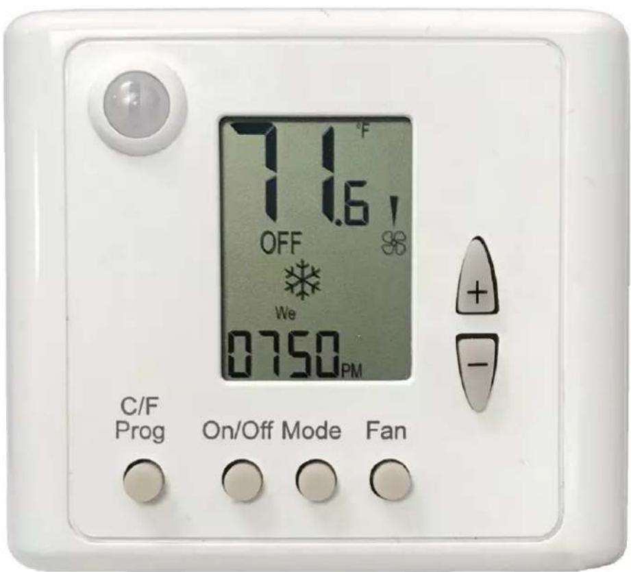
CARRIER CORPORATION ©2020 · Catalog No. 11-808-723-01 · 4/7/2020

Verify that you have the most current version of this document from www.hvacpartners.com or
www.accounts.ivusystems.com or your local Carrier office.
Important changes are listed in Document revision history at the end of this document.
CARRIER CORPORATION ©2020. All rights reserved throughout the world. i-Vu is a registered trademark of Carrier Corporation. All other trademarks are the property of their respective owners.
Contents
Overview 1
Specifications....2
TBPL-24-H Dimensions 4
Technician Settings Index....5
Operating Instructions....7
Quick Guide 7
Turning the thermostat ON and OFF....8
Selecting temperature scale....8
Adjusting the Setpoint temperature....8
Selecting system mode 9
Selecting fan speed (for 2 and 3 fan speeds configuration)....10
Turning Auto fan ON or OFF (fan on demand)....10
Locking the thermostat buttons....11
Economy mode 11
Freeze Protection....12
Economizer 12
Weekly program 14
MAC Address and BACnet Device Instance Number....19
Installation 21
General....21
Wiring terminals 22
DIP switch and jumper configurations 24
AC configurations....25
FC configurations for 2-pipe systems....26
FC configurations for 4-pipe systems / Floor heating....27
Wiring and DIP switch/jumper configurations 1 to 4 - AC systems....28
Wiring and DIP switch/jumper configurations 5 to 7 - AC systems....29
Wiring and DIP switch/jumper configurations 8 to 9 - AC systems....30
Wiring and DIP switch/jumper configurations 10 to 13 - AC systems.... 31
Wiring and DIP switch configurations 16 to 19 - AC systems....32
Wiring and DIP switch/jumper configurations 20 to 23 - FC systems - 2-pipe ....33
Wiring and DIP switch/jumper configurations 24 to 27 - FC systems - 4-pipe 34
Wiring and DIP switch/jumper configurations 28 to 30 - FC systems - 4-pipe .... 35
Wiring and DIP switch/jumper configurations 31 to 34 - FC systems - 4-pipe .... 36
Wiring and DIP switch/jumper configurations 35 to 38 - FC systems - 4-pipe .... 37
Wiring and DIP switch/jumper configuration 39 - FC systems - 4-pipe....38
Wiring and DIP switch/Jumper configurations 40 to 41 - FC systems - 4-pipe .... 39
Wiring and DIP switch/jumper configurations 42 to 44 - FC systems - 4-pipe .... 40
Wiring and DIP switch/jumper configurations 45 to 47 - FC systems - 4-pipe .... 41
Technician Settings 42
Technician Settings P01 to P03 42
Technician Settings P04 to P07 43
Technician Settings P08 to P10....44
Technician Settings P11 to P15....45
Technician Settings P16 to P25....46
Technician Settings P26 to P30....47
Technician Settings P31 to P34....48
Technician Settings P35 to P42....49
Technician Settings P43 to P44....50
Technician Settings P45 to P46....51
Contents
Technician Settings P47 to P48....52
Technician Settings P49 to P51....53
Technician Settings P52 to P57....54
Technician Settings P60 to P64....55
Technician Settings P65 to P70....56
Technician Settings P71 to P75....57
Technician Settings P76 to P79....58
Technician Settings P83 to P88....59
Technician Settings P89 to P99....60
Technician Settings P101 to P111....61
Technician Settings P114 to P119....62
Technician Settings P122 to P188....63
Technician Settings P189 to P195....64
Technician Settings P196 to P200....65
Alarms and indications 66
Document revision history....67
Overview
The Carrier Corporation ComfortVu™ BACnet Thermostat Model TB-24-HM can be used:
• As a stand-alone thermostat that can control equipment using built-in logic
• As part of an MS/TP network of BACnet Thermostats that can be managed from a BMS front-end system
- As part of a BACnet MS/TP network connected to the Carrier Corporation BACnet router in a i-Vu® system. The router's control programs provide trending and alarming of the BACnet Thermostat's data.
The TB-24-HM thermostat has a white plastic enclosure with an LCD display and buttons for user control. It has on-board temperature sensing, and its on-board inputs and outputs are used to control equipment and optional external sensing devices. Inputs and outputs are configured using DIP switches and jumpers. The TB-24-HM thermostat requires 24 Vac power.
Specifications
| Sensing element: | Range | Accuracy |
| Temperature | 41°F to 95°F (5°C to 35°C) | ±1.0°F (0.5°C) |
| Humidity | 10% to 90% | ±3.0% typical |
| Motion Sensing: | ||
| Sensor Type | PIR, quad, omnidirectional | |
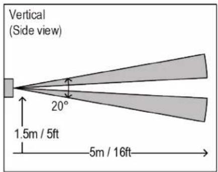
| Distance | 16.4 feet (5m) | |
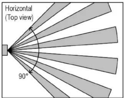
| Detection range | (HxV) 90° x 30° | |
| Movement speed | 2.62 to 3.94 ft/s (0.8 to 1.2 m/s) | |
| Detection object | 15.75 x 9.84 in. (400 x 250 mm) | |
| Power 24 Vac, ±10%, 50-60Hz, 4VA | ||
| NOTE Devices connected to outputs, such as a fan, will increase VA requirements. | ||
| Communication | BACnet MS/TP with baud rates up to 76.8 kbps (default baud rate is 38.4 kbps), detected and set automatically by the BACnet Thermostat. Max 127 devices. | |
| Inputs | T1, 0 - Normally open or normally closed dry contract, or0-10 Vdc analog input, or50 kOhm thermistor @ 25°CA, B - Communication +/- (RS485)IN1, 0 - Normally open or Normally closed dry contract, or0-10 Vdc analog input, or50 kOhm thermistor @ 25°C, R - Power: 24 Vac | |
| Outputs | 11, 12, 13 - Digital outputs, 3A max.14 - Digital outputs 0.3A max.15 and 16 - Depends on application.Digital output 0.3A max., orAnalog output 0-10 Vdc, 5 mA max., not isolated | |
| Environmental operating range | 50° to 122°F (10° to 50°C), 10 to 90% relative humidity, non-condensing | |
| Mounting | If using an electrical box, mount the included wallplate to a standard 4" x 2" electrical box using the two larger mounting screws, then mount the thermostat to the wallplate using the three smaller mounting screws.If not using an electrical box, flush-mount thermostat to wall (no wallplate needed). | |
Weight 4.8 oz (0.14 kg)
Compliance United States of America:
FCC CFR47, Chapter 1, Subchapter A, Part 15, Class B
Canada:
Industry Canada Compliant, ICES-003, Class B
Europe:
CE Mark, Low Voltage Directive: 2014/35/EU RoHS Compliant: 2011/65/EU
Australia and New Zealand:

C-Tick Mark, AS/NZS 61000-6-3
Title 24 compliant if connected to a BMS with custom programming for economizer fault detection.
CA Prop 65 Warning: This product can expose you to chemicals including Styrene and 1,3
- Propane sultone, which are known to the State of California to cause cancer. For more information, go to www.p65warnings.ca.gov.
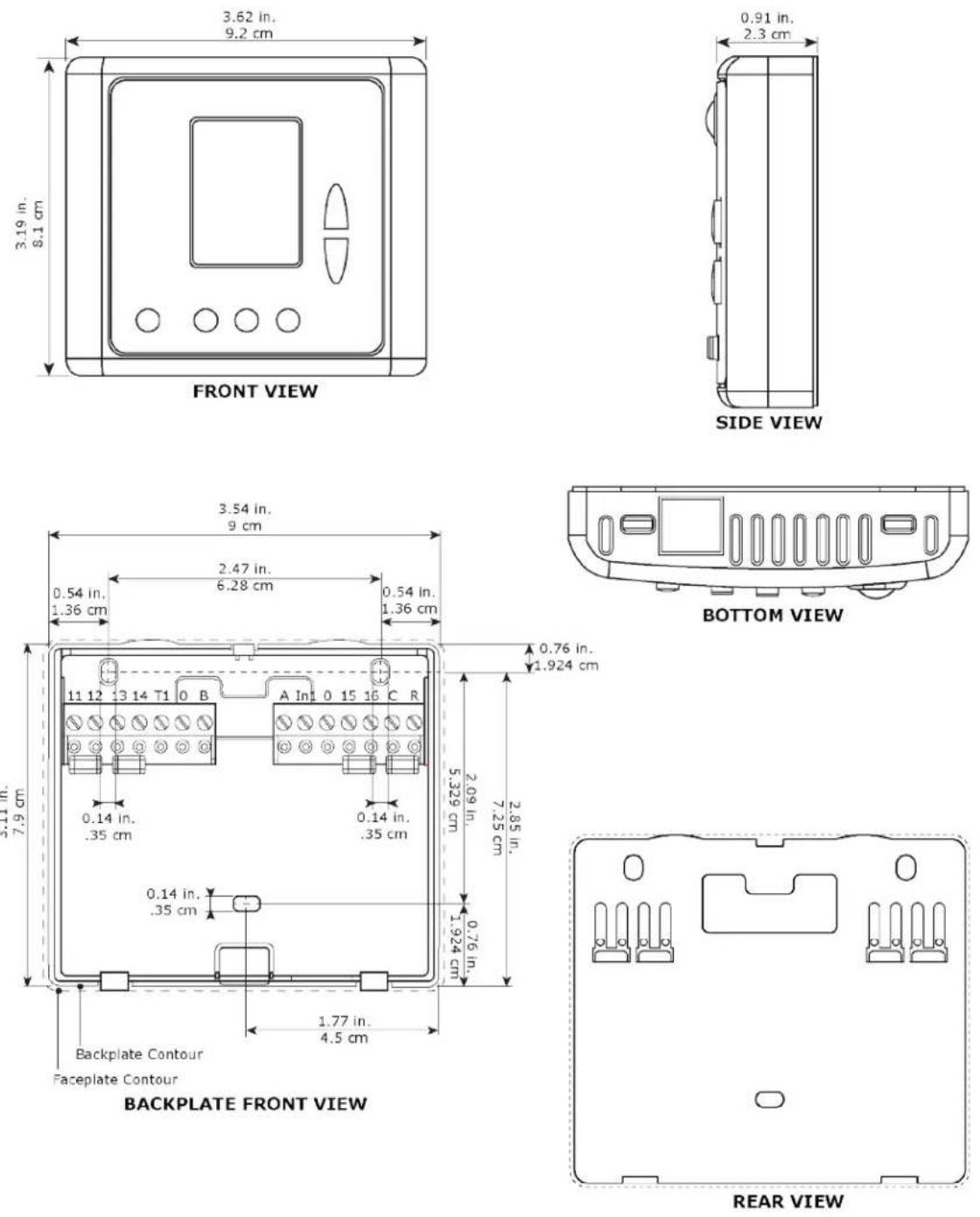
TBPL-24-H Dimensions
Technician Settings Index
| P01 - Offset for temperature readings calibration | P40 - View filter counter (hours) - Read only |
| P02 - Set point limit for cooling | P41 - Reset filter time |
| P03 - Set point limit for heating | P42 - Adjust filter alarm delay counter (hours) |
| P04 - Lock the [Fan] button | P43 - Soft start in heat - cut-in temperature |
| P05 - Lock the [Mode] button | P44 - Soft start in heat - cut-out temperature |
| P06 - Lock the [On/Off] button | P45 - Cool differential band |
| P07 - Lock the [+] and [-] buttons (Set buttons) | P46 - Cool differential band offset |
| P08 - Functionality of T1 terminals | P47 - Heat differential band |
| P09 - Functionality of IN1,0 terminals | P48 - Heat differential band offset |
| P10 - Window contact (terminals IN1,0) polarity | P49 - Shift between Cool and Heat in Auto mode |
| P11 - Window contact delay time | P50 - Shift between Cooling stages |
| P12 - Door switch (terminals T1,0) polarity | P51 - Shift between Heating stages |
| P13 - Door switch delay time | P52 - Cool valve proportional band |
| P14 - Enable/Disable Auto change over mode | P53 - Cool proportional low limit |
| P15 - Occupancy sensor logic (PIR) | P54 - Cool proportional high limit |
| P16 - Enable/Disable Occupancy sensor | P55 - Heat valve proportional band |
| P17 - PIR (occupancy sensor) delay time | P56 - Heat proportional low limit |
| P18 - Door switch or key tag configuration | P57 - Heat proportional high limit |
| P19 - PIR (Occupancy sensor) polarity | P60 - Proportional ON percent |
| P25 - Economy set point for cooling | P61 - Proportional OFF percent |
| P26 - Economy set point for heating | P63 - Time on-delay between cooling stages |
| P27 - On-delay time on-delay between heating stages | P64 - Time off-delay between cooling stages |
| P28 - Off-delay time between heating stages | P65 - Fan VFS proportional band in cooling |
| P30 - Beeper ON or OFF | P66 - Fan VFS proportional band in heating |
| P31 - Fan ON delay in cooling | P67 - Fan VFS Low speed percent in cooling |
| P32 - Fan OFF delay in cooling | P68 - Fan VFS Medium speed percent in cooling |
| P33 - Fan ON delay in heating | P69 - Fan VFS High speed percent in cooling |
| P34 - Fan OFF delay in heating | P70 - Fan VFS Low speed percent in heating |
| P35 - Enable/Disable Freeze protection | P71 - Fan VFS Medium speed percent in heating |
| P36 - Freeze protection cut-in set point | P72 - Fan VFS High speed percent in heating |
| P37 - Freeze protection cut-out set point | P74 - VFS Medium speed differential |
| P75 – VFS High speed differential | P109 – Weekly program event configuration |
| P76 – Fan VFS Low limit in cooling | P111 – PIR Sensitivity |
| P77 – Fan VFS High limit in cooling | P114 – Cool PID Kp |
| P78 – Fan VFS Low limit in heating | eat PID Kp |
| P79 – Fan VFS High limit in heating | P116 – Cool PID Ki |
| P83 – View T2 temperature sensor readings | P117 – Heat PID Ki |
| P84 – View T3 temperature sensor readings | P118 – Cool PID Kd |
| P85 – Deice in cool – cut-in temperature | P119 – Heat PID Kd |
| P86 – Deice in cool – cut-out temperature | P122 – Cool Proportional output threshold time |
| P87 – Deice in heat time | P123 – Heat Proportional output threshold time |
| P88 – Deice in heat break time | P160 – Minimum compressor ON time |
| P89 – Deice in heat – cut-in temperature | P161 – Minimum compressor OFF time |
| P90 – Deice in heat – cut-out temperature | P170 – Economizer low limit temperature |
| P91 – Compressor delay | P193 – Display switching time (between temp and hum) |
| P98 – Display set point only (hide room temperature) | P194 – Humidity differential band |
| P99 – One or Two set points | P195 – Humidity sensor reading offset |
| P101 – Screen dimming delay | Dead zone between humidification and dehumidification |
| P107 – Weekly program configuration | umidity setpoint |
| P108 – Weekly program - events per day | P198 – Not in use |
| P200 – Restore defaults |
Press the [On/Off] button or wait 60 seconds to return to normal display.
Operating Instructions
Quick Guide
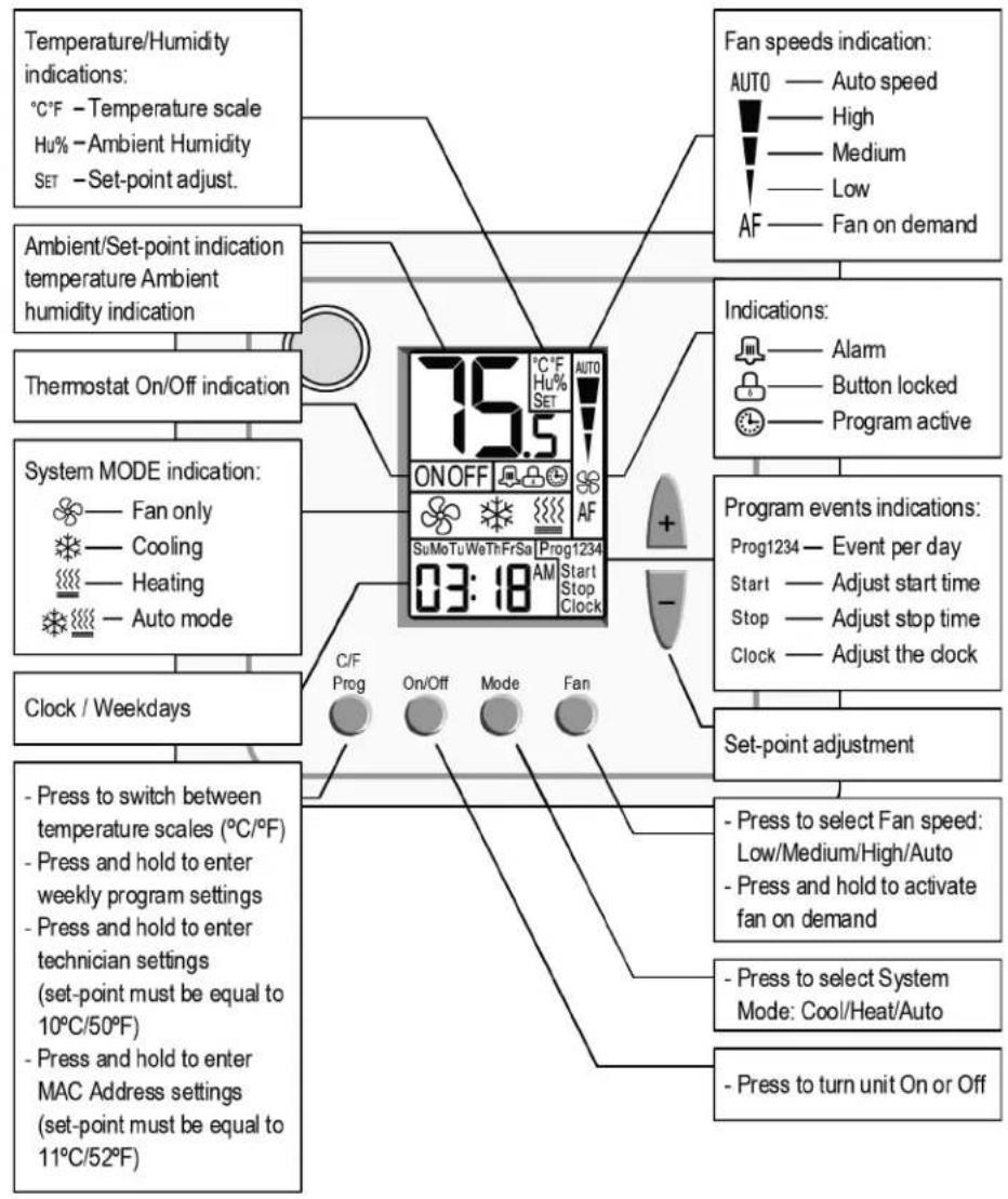
flowchart
graph TD
    A["Temperature/Humidity indications: °C/F - Temperature scale<br>Hu% - Ambient Humidity<br>SET - Set-point adjust."] --> B["75.5 ON/OFF"]
    C["Ambient/Set-point indication temperature Ambient humidity indication"] --> B
    D["Thermostat On/Off indication"] --> B
    E["System MODE indication: Fan only<br>Cooling<br>Heating<br>Auto mode"] --> B
    F["Clock / Weekdays"] --> B
    G["Press to switch between temperature scales (°C/°F) <br>Press and hold to enter weekly program settings <br>Press and hold to enter technician settings (set-point must be equal to 10°C/50°F) <br>Press and hold to enter MAC Address settings (set-point must be equal to 11°C/52°F)"] --> B
    H["Fan speeds indication: AUTO — Auto speed — High — Medium — Low — AF — Fan on demand"] --> B
    I["Indications: Alarm — Button locked — Program active"] --> J["Program events indications: Prog1234 — Event per day — Start — Adjust start time — Stop — Adjust stop time — Clock — Adjust the clock"]
    J --> K["Set-point adjustment"]
    L["Press to select System Mode: Cool/Heat/Auto"] --> K
    M["Press to turn unit On or Off"] --> K
Turning the thermostat ON and OFF
Press the [On/Off] button to turn the thermostat ON or OFF.
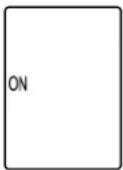
ON
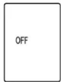
OFF
Selecting temperature scale
[C/F] button to switch between temperature scales.
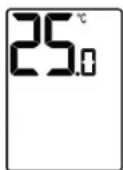
Celsius
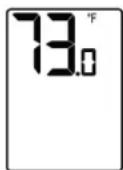
Fahrenheit
Adjusting the Setpoint temperature
Note: The setpoint must be different than 10, 11°C/50, 52°F.
In One setpoint configuration:
1 Press the [+] or [-] buttons once to view the setpoint temperature.
2 Press again to adjust the setpoint.
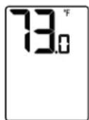
Set point
In Two setpoints configuration:
1 Press the [+] or [-] buttons once - "※" and the setpoint temperature for cooling will appear on display.
2 Use the [+] or [-] buttons to adjust the setpoint for cooling.
3 Press the [Mode] button or wait 3 seconds. "..." and the setpoint temperature for heating will appear on display.
4 Use the [+] or [-] buttons to adjust the setpoint for heating.
- The setpoint for cooling must be higher than the setpoint for heating.
• For humidity setpoint, see Technician Setting P197.
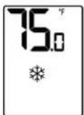
Setpoint
For cooling
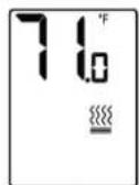
Setpoint
For heating
Selecting system mode
Press the [Mode] button to switch between system modes.
Notes:
- During demand for cooling or heating, the active mode will flash.
• In Auto mode, the active mode icon (Cool or Heat) will flash.
• Auto mode is not available in 2-Pipe system configuration.
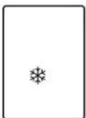
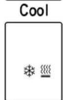
Auto
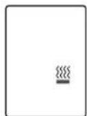
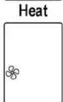
Fan only
Selecting fan speed (for 2 and 3 fan speeds configuration)
Press the [Fan] button to switch between fan speeds.
Notes:
• In Auto speed, the active fan speed icon will appear on display.
• Medium speed available in 3 speeds configuration.
- Auto Speed in AC configurations: the differential parameter (speed change between stages) is determined by constant 0.7^ C ( 1.4^ F)
- Auto Speed in FC configurations: the differential parameter is determined by object AV#59 - DifferentialOnOffFanSpeed
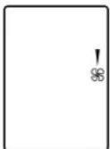
Low
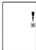
Medium
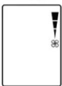
High
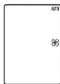
Auto
Turning Auto fan ON or OFF (fan on demand)
In 1-speed configuration:
Press the [Fan] button to turn Auto fan ON or OFF.
In 2- and 3-speed configurations:
Press and hold the [Fan] button for 7 seconds to turn Auto fan ON or OFF.
- When ON, the fan will run on demand for cooling or heating.
- When OFF, the fan will run continuously.
Note: Auto fan cannot be selected in Fan only mode.
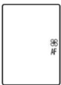
Auto fan OFF
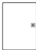
Auto fan ON
Locking the thermostat buttons
- Press and hold the [Mode] button for 7 seconds to lock or unlock the thermostat buttons.
- When locked, the lock ( 🔍 ) icon will appear on display with any attempt to press the buttons.
- Enable or disable the option to lock different buttons using Technician Settings P04-P07.
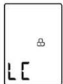
Lock indications
Lock indications
Economy mode
Activate Economy mode by triggering a window contact - remote on/off switch, window contact - remote economy switch, door switch, key-tag, External motion sensor (PIR - passive infrared sensor) or through communication - binary value "UnoccupiedByNetwork".
| E1 | Economy by Window contact - Remote On/Off switch - Turning unit offEconomy by Window contact - Remote economy switch - Using economy set pointsRefer to technician parameters P25 and P26 for economy set points |
| E2 | Economy by External motion sensor (PIR) or through Communication (binary value “UnoccupiedByNetwork”)Refer to technician parameter P15 “Occupancy sensor logic (PIR)” |
| E4 | Economy triggered by Door switchRefer to technician parameter P18 “Door switch or key tag configuration” |
| E5 | Economy by Key-tagRefer to technician parameter P18 “Door switch or key tag configuration” |
Freeze Protection
The Freeze protection feature will not allow the room temperature to drop below predefined cut-in temperature. Depending on which configuration the system is operating under (W/WO Heat pump), this feature will force the system to operate in heat mode and activate the fan.
This feature will take effect when the thermostat is either ON or OFF. When the room temperature rises above the predefined cut-out temperature, the thermostat will return to its previous state.
When freeze protection is activated, the display alternates between "AL" and room temperature.
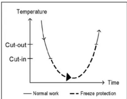
line
| Time | Temperature (Normal work) | Temperature (Freeze protection) | |------|---------------------------|----------------------------------| | 0 | High | Low | | 1 | Medium | Medium | | 2 | Low | Low | | 3 | Very Low | Very Low | | 4 | High | High |Economizer
Economizer is used to reduce the energy consumed by the cooling systems, by using low external air temperatures to assist in the chilling process. When outdoor temperatures are lower relative to indoor (room) temperatures, the system utilizes the cool outdoor air as a free cooling source.
The outdoor temperature (Teconomizer) triggering the activation of the economizer, can be measured by the temperature sensor connected to T1,0 terminals (technician parameter P08="05") or by setting a temperature value manually through communication - AV#129 "TEconomizerEffective".
When getting the temperature through communication, terminals T1,0 can be used for any other functionality like External sensor/Soft start in heat sensor/De-icing in cool/Door switch/Key tag.
Whenever there is demand for cooling and the outdoor temperature conditions allow the operation of the economizer, it will operate together with the regular cooling system and will not replace it.
Economizer will start when, and run as long as, both of the following conditions are satisfied:
1 Teconomizer temperature < Room temperature - (Cool differential band / 2)
2 Room Temperature > Setpoint temperature
Economizer will stop when the following condition is satisfied:
Room Temperature < Setpoint temperature - (Cool differential band / 2)
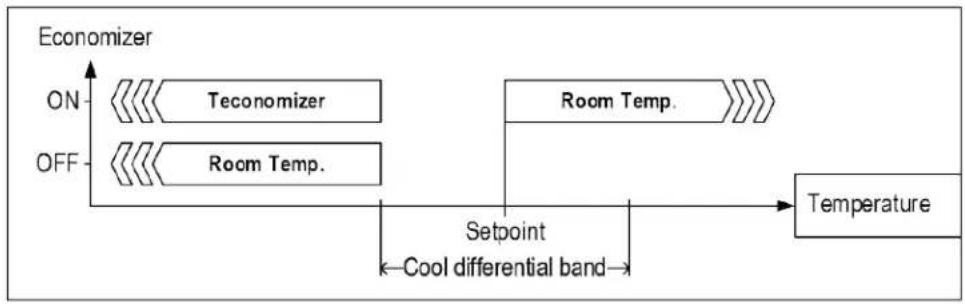
flowchart
graph LR
    A["Teconomizer"] --> B["Room Temp."]
    C["Room Temp."] --> D["Setpoint"]
    D --> E["Cool differential band"]
    E --> F["Temperature"]
    style A fill:#f9f,stroke:#333
    style B fill:#ccf,stroke:#333
    style C fill:#cfc,stroke:#333
    style D fill:#fcc,stroke:#333
    style E fill:#cff,stroke:#333
    style F fill:#ffc,stroke:#333
Indication for the Economizer operation:
When Economizer is active, the "Cool" symbol will appear (or flash when active) on display and the "Fan" symbol will flash.
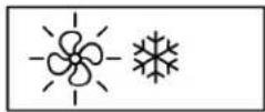
Economizer Active
Weekly program
General
Prior to programming, make sure that Technician Settings P107, P108, and P109 are configured correctly.
Program types
The thermostat can be configured to run four different types of weekly programs (set by Technician Setting P107):
• 7-day program with same parameters for all days.
• 7-day program with different parameters for each day of the week.
• One schedule for the weekdays (Monday to Friday), one schedule for Saturday and another one for Sunday.
• One schedule for the weekdays (Monday to Friday) and another one for Saturday and Sunday.
Daily events
Each daily program can use 2 or 4 schedule events per day (set by Technician Setting P108).
There are two options for settings the schedule events (set by Technician Setting P109):
• "EU Type" - Start time and Stop time.
- "US Type" - Start time, setpoint temperatures, system mode and fan speed.
IMPORTANT
- Parameter P107 must not be equal to "0" in order to enable weekly program capabilities.
- Changing P107 to "0" will disable all program capabilities and reset programmed information.
Enabling/Temporarily Disabling/Overriding the program
• Activate the program
- When the program is activated, a clock icon appears on the display.
If a clock icon does not appear, ensure that the set-point temperature is not 10/11°C or 50/52°F, press and hold the button to activate the program.

- Temporarily disable the program - without losing programmed information – for example, when out of the office or leaving for vacation:
- Make sure that the set-point temperature is not 10/11°C or 50/52°F.
Press and hold the button to temporarily disable the program.
Press and hold the button again to reactivate to the program.
- Override the program - the occupant can temporarily change the set point temperature to be different than the set point temperature specified by the program. Changes remain in effect until the next program event begins.
Programming procedure
- The detailed programming procedure is described in the next sections. Make sure to follow the right programming procedure, suitable for the program type and features selected by Technician Settings.
- Press the [C/F-Prog] button to enter and proceed through the steps of the real time clock and programming procedure.
• Use the [+] or [-] buttons to select or change value of a flashing icon. - It is recommended to select programming values prior to the actual programming.
Exit the programming procedure
At any time during the programming procedure, press the [On/Off] button to exit and return to normal display. Any changed values will be saved.
Adjusting the time and day of the week
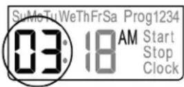
- Press and hold the [C/F-Prog] button. The word "Clock" will appear on display, and the HOURS will flash.
Hours
- Use the [+] or [-] buttons to adjust the hours.
Minutes
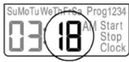
- Press the [C/F-Prog] button again. The MINUTES will flash.
- Use the [+] or [-] buttons to adjust the hours.
Days
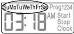
- Press the [C/F-Prog] button again. The DAYS will flash.
- Use the [+] or [-] buttons to select the day.
- If Technician Setting P107 is not set to "00" (program is enabled), press the [C/F-Prog] button to enter programming procedure. Be sure to follow the right programming procedure, suitable for the program type and features selected by Technician Settings.
Section C - "EU Type"
Section D - "US Type"
Otherwise, press the [C/F-Prog] button to return to normal display.
Adjusting "EU type" daily programs
Start time
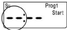
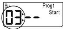
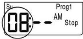
- Press the [C/F-Prog] button. The programmed weekday(s), "Prog 1" indicating the first program event of the day and the word "Start" will appear on display.
The HOURS will flash.
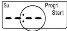
Note: If this is the first time a program is being set, the symbols “-” will flash.
- Use the [+] and [-] buttons to adjust the start time hours of the first event.
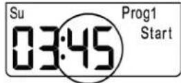
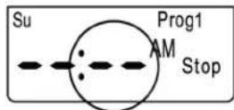
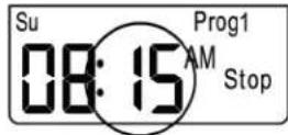
- Press the [C/F-Prog] button again. The MINUTES will flash.
- Use the [+] and [-] buttons to adjust the start time minutes of the first event.
Stop time
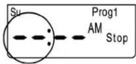
- Press the [C/F - Prog] button again. T the word "Stop" will appear on display, and the HOURS will flash.
- Use the [+] and [-] buttons to adjust the stop time hours of the first event
-
Press the [C/F-Prog] button again. The MINUTES will flash
-
Use the [+] and [-] buttons to adjust the stop time minutes of the first event
- Follow the steps above for the other schedule events of the same daily period (P2 for two events per day, or P2, P3, and P4 for four events per day).
• Follow the steps above for all daily periods.
Adjusting "US type" daily programs
Start time
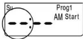
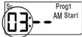
- Press the [C/F-Prog] button. The programmed weekday(s), "Prog 1" indicating the first program event of the day and the word "Start" will appear on display.
The HOURS will flash.
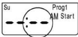
Note: If this is the first time a program is being set, the symbols “--” will flash.
- Use the [+] and [-] buttons to adjust the start time hours of the first event.
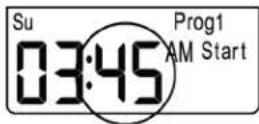
- Press the [C/F-Prog] button again. The MINUTES will flash.
- Use the [+] and [-] buttons to adjust the start time minutes of the first event.
System mode and fan speed
- Press the [C/F-Prog] button again. The system MODES will flash.
- Use the [+] and [-] buttons to select the system mode of the first event
- Press the [C/F-Prog] button again. The FAN SPEEDS will flash.
- Use the [+] and [-] buttons to select the fan speed of the first event.
Setpoint
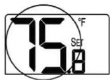
- Press the [C/F - Prog] button again. The setpoint will flash.
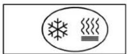
Note: If the thermostat is configured to have two setpoints, first adjusts the setpoint for cooling and then the setpoint for heating.
- Use the [+] and [-] buttons to adjust the setpoint of the first event.
- Follow the steps above for the other schedule events of the same daily period (P2 for two events per day, or P2, P3 and P4 for four events per day).
• Follow the steps above for all daily periods.
MAC Address and BACnet Device Instance Number
MAC Address
To set the communication MAC Address:
1 Adjust the setpoint temperature to 11^ C or 52^ F.
2 Press and hold the [C/F] button for 10 seconds to enter MAC Address configuration mode.
3 Use the [+] or [-] buttons to define the MAC Address (range 1...127).
4 When finished, press the [On/Off] button and readjust the setpoint.
5 Switch power supply off and on again for the MAC address changes to take effect.
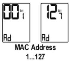
Caution: Do not use the same MAC address for two devices on the same communication bus!
BACnet Device Instance Number
By default, the BACnet Device Instance Number is generated automatically by the thermostat (Vendor ID + MAC address). For example, Carrier Corporation vendor ID is 16, and if the MAC address is 075, the BACnet Device Instance Number is 16075.
Note: If you change the MAC address, you must cycle the thermostat's power to reset the BACnet Device Instance Number.
You can override the automatically-generated BACnet Device Instance Number using the i-Vu® application, an Analog Network Output microblock in a control program, or some other BACnet utility. Write the new BACnet Device Instance Number to the present_value property of Analog Value 42 (BACnetDeviceInstanceNumber).
Examples:
In the i-Vu® application
1 Use the BACnet Discovery feature to discover the BACnet Thermostat and its BACnet objects.
2 In the navigation tree, select the Analog Value called BacnetDeviceInstanceNumber.
3 Change the Present Value field (shown below) to the desired BACnet Device Instance Number.
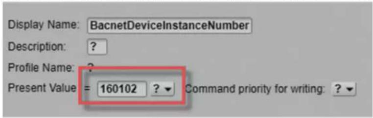
4 Click Accept.
In an Analog Network Output microblock
To change the BACnet Device Instance Number from 16075 to 16113, the microblock's address would be:
bacnet://16075/AV:42/present_value,or
bacnet://16075/BACnetDeviceInstanceNumber
Subsequent reads/writes of this value will need to be done with the new device instance:
bacnet://16113/AV:42/present_value,or
bacnet://16113/BACnetDeviceInstanceNumber
Installation
Mount the BACnet Thermostat on an interior wall in the room to be controlled. Locate it where the occupant can easily read the LCD display and use the controls. If the built-in temperature sensor is being used to measure room temperature, place the thermostat where the temperature is representative of the general room conditions. Avoid cold or warm air drafts, radiant heat, and direct sunlight.

WARNING: Risk of electric shock and property damage. Disconnect power supply before making electrical connections. The installation is to be performed by a qualified electrician.

WARNING: The integrated circuits in the controller are sensitive to static currents. Take suitable precautions.
General
Installation procedure
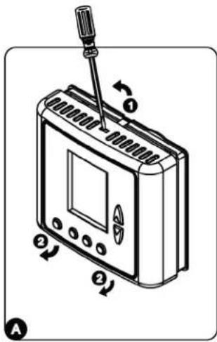
A. Separate the front panel from the back panel by pressing the tab located in the top of the unit and pulling the back panel off of the two bottom tabs.
B. Do one of the following:
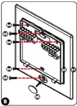
- If using an electrical box, mount the included wallplate to a standard 4" x 2" electrical box using the two larger mounting screws, then mount the thermostat to the wallplate using the three smaller mounting screws. Insert the screw cap into the wallplate's bottom screw hole.
- If not using an electrical box, flush-mount the thermostat to the wall (no wallplate needed).
C. Make electrical connections as shown in the picture below and the wiring diagram (page 22). Set DIP switch positions as explained in this manual.
D. Reattach the cover by placing it on the back panel's two bottom tabs and then pushing the cover until the top tab clicks into its slot on the cover.
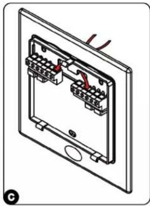
natural_image
Technical line drawing of an electrical switch panel with two terminal blocks and wiring (no text or symbols)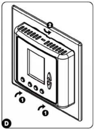
PIR detection area
Wiring terminals
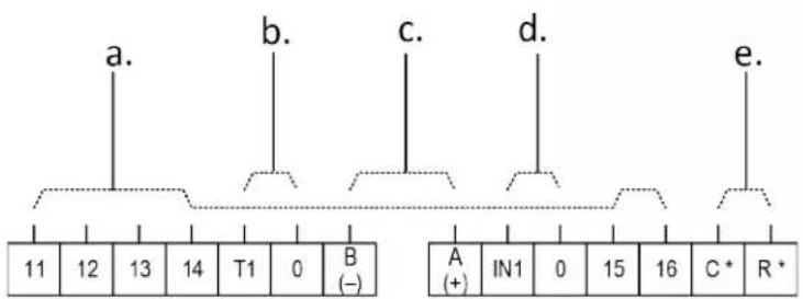
Terminals
a For outputs 11-16, see Wiring and DIP switch/jumper settings (page 28).
b For T1,0 inputs: Dry contact, 10 Vdc input, or 50 kOhm thermistor See Technician Setting P8.
c MS/TP Communication (RS485): BACnet
d For IN1,0 functionality – please refer to parameter P9 in the technician settings section.
T2 change over sensor / Soft start in heat sensor / Window contact Remote On/Off switch / Window contact Remote economy switch / External PIR
e Power supply: 24 Vac

CAUTION Do not connect line voltage to a thermostat that does not show the following symbol: 110-230V
DIP switch and jumper configurations
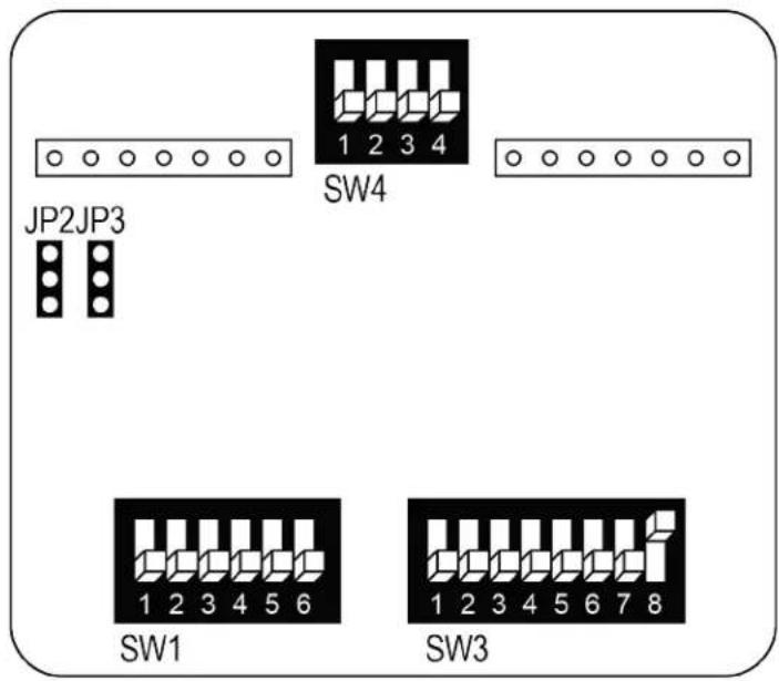
SW4.1 - Without valves control in FC config.
OFF - Enable valves control
ON - Disable valves control
SW4.2 - Enable/Disable PIR detector
OFF - Enable PIR detector
ON - Disable PIR detector
SW4.3 - Not used
Always OFF
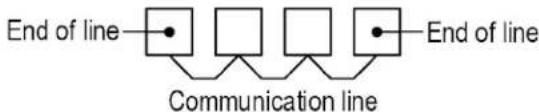
SW4.4 - End of line resistor (120Ω)
OFF = Not end of line
ON = End of line
flowchart
graph LR
    A["•"] --> B["□"]
    B --> C["□"]
    C --> D["•"]
    D --> E["End of line"]
    style A fill:#fff,stroke:#000
    style B fill:#fff,stroke:#000
    style C fill:#fff,stroke:#000
    style D fill:#fff,stroke:#000
    style E fill:#fff,stroke:#000
    subgraph Communication line
        B
        C
        D
    end
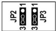
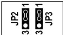
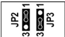
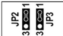
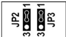
JP2, JP3 - Outputs 15,16 - Analog or Digital
JP2 - Output 16
Position 1- Analog output
Position 3- Digital output
JP3 - Output 15
Position 1- Analog output
Position 3- Digital output
SW1.1 through SW1.6, and SW3.1 through SW3.8
See Wiring and DIP switch/jumper settings (page 28).
AC configurations
Find the configuration you want in the tables below, then find that configuration number (1 through 9) on the Wiring and DIP switch/jumper settings.
AC Configurations without humidification/dehumidification
| Outputs | Configuration | 1 | 2 | 3 | 4 | 5 | 6 | 7 | 8 | 9 | |||
| Heat elements (max.) | 3 2 | 1 2 | 1 2 | 1 | |||||||||
| Compressors (max.) | 2 2 | 2 1 1 1 | 1 2 2 | ||||||||||
| Heat pump | • • | • | • | • | |||||||||
| Fan VFS | • • | ||||||||||||
| Fan speeds | 1 1 | 2 or 3 2 | or 3 2 or 3 | 1 1 | |||||||||
| Economizer | ○ | ○ | ○ | ○ ○ | ○ ○ | ||||||||
| Humidifier | |||||||||||||
| Dehumidifier | |||||||||||||
| Reheat (Dehumidify) | |||||||||||||
AC Configurations with humidification/dehumidification
| Outputs | Configuration | 10 | 11 | 13 | 14 | 15 | 16 | 17 | 18 | 19 | |||
| Heat elements | 2 2 | 1 1 1 | 1 2 1 | 1 | |||||||||
| Compressors | 2 1 | 1 1 2 | 1 1 1 | 1 | 1 | ||||||||
| Heat pump | • | • | • | • | • | ||||||||
| Fan VFS | |||||||||||||
| Fan speeds | 1 1 | 2 or 3 | 2 or 3 | 1 1 | 1 1 | 1 | 1 | ||||||
| Economizer | ○ | ○ | ○ | ○ | ○ | ○ | |||||||
| Humidifier | • | • | • | • | • | • | • | • | • | ||||
| Dehumidifier | • | • | • | • | |||||||||
| Reheat (Dehumidify) | • | • | • | • | • | ||||||||
- Yes - Option
FC configurations for 2-pipe systems
Find the configuration you want in the tables below, then find that configuration number (20 through 23) on Wiring and DIP switch/jumper settings.
FC Configurations for 2-Pipe systems without humidification/dehumidification
| Outputs | Configuration | 20 | 21 | 22 | 23 | ||||
| CI/Ht valve / CI/Ht valve PID | • PID | • PID | |||||||
| Heat element (2nd stage) | • • | • • | |||||||
| Fan VFS | • • | ||||||||
| Fan speeds | 1 | 2 | 3 | 1 | 2 | 3 | |||
| Economizer | ○ | ○ | ○ | ○ ○ | |||||
| Humidifier | |||||||||
| Dehumidifier | |||||||||
| Reheat (Dehumidify) | |||||||||
FC Configurations for 2-Pipe systems with humidification/dehumidification
| Outputs | Configuration | 24 | 25 | 26 | 27 | 28 | 29 | 30 | ||||||||||
| CI/Ht valve / CI/Ht valve PID | • PID • PID | • PID • | ||||||||||||||||
| Heat element (2nd stage) | • • | • • | • | |||||||||||||||
| Fan VFS | • • | • | ||||||||||||||||
| Fan Speeds | 1 | 2 | 3 | 1 | 2 | 3 | 1 | 2 | 3 | 1 | 2 | 3 | ||||||
| Economizer | ○ | ○ | ○ | ○ | ○ ○ | ○ | ○ | ○ | ○ | ○ | ○ | |||||||
| Humidifier | • • | • | ||||||||||||||||
| Dehumidifier | • • | • | ||||||||||||||||
| Reheat (Dehumidify) | • • | • • | ||||||||||||||||
- Yes - Option
FC configurations for 4-pipe systems / Floor heating
Find the configuration you want in the tables below, then find that configuration number (31 through 39) on the Wiring and DIP switch/jumper settings.
FC Configurations for 4-Pipe systems without humidification/dehumidification
| Outputs | Configuration | 31 | 32 | 33 | 34 | 35 | 36 | 37 | 38 | 39 | ||||||||||||
| Cool valve / Cool valve PID | • | • | PID | PID | • | • | • | PID | PID | |||||||||||||
| Heat valve / Heat valve PID | • | • | • | • | • | PID | PID | • | PID | |||||||||||||
| Heat element (2nd stage) | • | • | • | • | ||||||||||||||||||
| Fan VFS | • | • • | ||||||||||||||||||||
| Fan speeds | 1 | 2 | 3 | 1 | 2 | 3 | 1 | 2 | 3 | 1 | 2 | 3 | 1 | 2 | 3 | 1 | 2 | 3 | ||||
| Economizer | ○ | ○ | ○ | ○ | ○ | ○ | ○ | ○ | ○ | ○ | ○ | ○ ○ | ○ | ○ | ||||||||
| Humidifier | ||||||||||||||||||||||
| Dehumidifier | ||||||||||||||||||||||
| Reheat (Dehumidify) | ||||||||||||||||||||||
| Floor heating | • | • | ||||||||||||||||||||
FC Configurations for 4-Pipe systems with humidification/dehumidification
| Outputs | Configuration | 40 | 41 | 42 | 43 | 44 | 45 | 46 | 47 | ||||||||||||||||
| Cool valve / Cool valve PID | • PID | • PID | • • | PID • | |||||||||||||||||||||
| Heat valve / Heat valve PID | • • | • • PID | • • | PID | |||||||||||||||||||||
| Heat element (2nd stage) | • • | ||||||||||||||||||||||||
| Fan VFS | |||||||||||||||||||||||||
| Fan speeds | 1 | 2 | 3 | 1 | 2 | 3 | 1 | 2 | 3 | 1 | 2 | 3 | 1 | 2 | 3 | 1 | 2 | 3 | 1 | 2 | 3 | 1 | 2 | 3 | |
| Economizer | ○ | ○ | ○ | ○ | ○ | ○ | ○ | ○ | ○ | ○ | ○ | ○ | ○ | ||||||||||||
| Humidifier | • • | • | |||||||||||||||||||||||
| Dehumidifier | • • | • | |||||||||||||||||||||||
| Reheat (Dehumidify) | • • | ||||||||||||||||||||||||
| Floor heating | |||||||||||||||||||||||||
- Yes - Option
Wiring and DIP switch/jumper configurations 1 to 4 - AC systems
| Outputs | Config. 1: HC321 Speed fan | Config. 2: HP421 Speed fan | Config. 3: HP222/3 Speeds fan | Config. 4: HP212/3 Speeds fan |
| 11 | Heat element 3 (3rd stage heat) | Heat element 2 (4th stage heat) | Fan high | Fan high |
| 12 | Heat element 2 (2nd stage heat) | Heat element 1 (3rd stage heat) | Fan medium (or Economizer(5)) | Fan medium (or Economizer(5)) |
| 13 | Fan (1 speed) | Fan (1 speed) | Fan low | Fan low |
| 14 | Compressor 2 | Compressor 2 | Compressor 2 | Heat element(2) |
| 15 | Compressor 1(3) | Compressor 1(3) | Compressor 1(3) | Compressor(3) |
| 16 | Heat element 1(2)(1st stage heat) | Heat pump(2) | Heat pump(2) | Heat pump(2) |
| SW3 | ||||
| SW1 | ||||
| JumpersJP2, JP3analogoutputs |
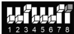
(1) SW3.1, SW3.2 - Fan speeds:
2 speeds (Low and High):
3 speeds (Low, Med., and High):
SW3.1 = OFF, SW3.2 = ON
SW3.1 = OFF, SW3.2 = OFF
(2) SW3.4 - HP (Heat pump): HC (not heat pump):
ON = Heat pump active in cool, OFF = Heat pump active in heat
ON = Electrical heater, OFF = Oil/Gas heater (no fan)
(3) SW3.5 - Compressor delay:
ON = Disable, OFF = Enable
(4) SW1.3 - Dehumidification:
ON = Use dehumidifier, OFF = Use reheat for dehumidification
(5) SW1.6 - Terminal 12 operation:
ON = Economizer
OFF = Fan Medium (3 speeds) / Terminal not in use (2 speeds)
Important: Economizer will not work in 3 fan speeds configuration.
See drawing for DIP switch and jumper locations (page 24).
Control - Fan on/off, Heat elements, Heat pump, Compressors, Economizer: 24 Vac, 0.5A max
Wiring and DIP switch/jumper configurations 5 to 7 - AC systems
| Outputs | Config. 5: HC212/3 Speeds fan^(1) | Config. 6: HP11Fan VFS | Config. 7: HC11Fan VFS |
| 11 | Fan high | X | X |
| 12 | Fan medium (or Economizer^(5) ) | Economizer^(5) (option - SW1.6 ON) | Economizer^(5) (option - SW1.6 ON) |
| 13 | Fan low | X | X |
| 14 | Heat element 2 (2nd stage heat) | Heat pump^(2) | Heat element^(2) |
| 15 | Compressor^(3) | Compressor^(3) | Compressor^(3) |
| 16 | Heat element 1^(2) (1st stage heat) | Fan VFS | Fan VFS |
| SW3 | 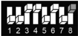 | 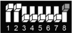 | 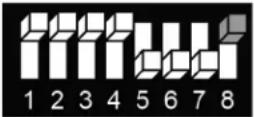 |
| SW1 | |||
| JumpersJP2, JP3 analog outputsW2 |
(1) SW3.1, SW3.2 - Fan speeds:
2 speeds (Low and High):
SW3.1 = OFF, SW3.2 = ON
3 speeds (Low, Med., and High):
SW3.1 = OFF, SW3.2 = OFF
(2) SW3.4 - HP (Heat pump): HC (not heat pump):
ON = Heat pump active in cool, OFF = Heat pump active in heat
ON = Electrical heater, OFF = Oil/Gas heater (no fan)
(3) SW3.5 - Compressor delay:
ON = Disable, OFF = Enable
(4) SW1.3 - Dehumidification:
ON = Use dehumidifier, OFF = Use reheat for dehumidification
(5) SW1.6 - Terminal 12 operation:
ON = Economizer
OFF = Fan Medium (3 speeds) / Terminal not in use (2 speeds)
Important: Economizer will not work in 3 fan speeds configuration.
See drawing for DIP switch and jumper locations (page 24).
Fan VFS: 0-10 Vdc, 0.5 mA Not isolated
Control - Fan on/off, Heat elements, Heat pump, Compressors, Economizer: 24 Vac, 0.5A max
Wiring and DIP switch/jumper configurations 8 to 9 - AC systems
| Outputs | Config. 8: HC221 Speed fan, Economizer, | Config. 9: HP321 Speed fan, Economizer |
| 11 | Heat element 2(2nd stage heat) | Heat element(3rd stage heat) |
| 12 | Economizer(5)(option - SW1.6 ON) | Economizer(5)(option - SW1.6 ON) |
| 13 | Fan (1 speed) | Fan (1 speed) |
| 14 | Compressor 2 | Compressor 2 |
| 15 | Compressor 1(3) | Compressor 1(3) |
| 16 | Heat element 1(2)(1st stage heat) | Heat pump(2) |

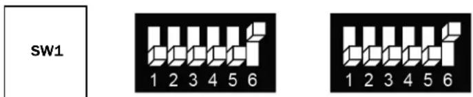
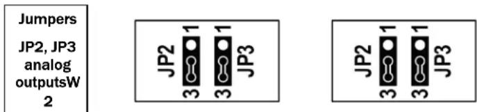
(1) SW3.1, SW3.2 - Fan speeds:
2 speeds (Low and High):
SW3.1 = OFF, SW3.2 = ON
3 speeds (Low, Med., and High):
SW3.1 = OFF, SW3.2 = OFF
(2) SW3.4 - HP (Heat pump): HC (not heat pump):
ON = Heat pump active in cool, OFF = Heat pump active in heat ON = Electrical heater, OFF = Oil/Gas heater (no fan)
(3) SW3.5 - Compressor delay:
ON = Disable, OFF = Enable
(4) SW1.3 - Dehumidification:
ON = Use dehumidifier, OFF = Use reheat for dehumidification
(5) SW1.6 - Terminal 12 operation:
ON = Economizer OFF = Fan Medium (3 speeds) / Terminal not in use (2 speeds) Important: Economizer will not work in 3 fan speeds configuration.
See drawing for DIP switch and jumper locations (page 24).
Control - Fan on/off, Heat elements, Heat pump, Compressors, Economizer: 24 Vac, 0.5A max
Wiring and DIP switch/jumper configurations 10 to 13 - AC systems
w/wo Humidifier for humidification, with Reheat for dehumidification
| Outputs | Config. 10: HC221 Speed fan, Humidifier, Reheat for Dehumidification | Config. 11: HP311 Speed fan, Humidifier, Reheat for Dehumidification | Config. 12: HC112/3 Speeds fan, Humidifier, Reheat for Dehumidification | Config. 13: HP212/3 Speeds fan, Reheat for Dehumidification |
| 11 | Heat element 2(2nd stage heat) | Heat element 2(2nd stage heat) | Fan high | Fan high |
| 12 | Heat element 1^(2) (1st stage heat) | Heat element 1^(2) (2nd stage heat) | Fan medium(or Economizer ^(5) ) | Fan medium(or Economizer ^(5) ) |
| 13 | Fan (1 speed) | Fan (1 speed) | Fan low | Fan low |
| 14 | Compressor 2 | Heat Pump ^(2) | Heat element ^(2) | Heat element ^(2) (2nd stage heat) |
| 15 | Compressor 1^(3) | Compressor ^(3) | Compressor ^(3) | Compressor ^(3) |
| 16 | Humidifier | Humidifier | Humidifier | Heat pump ^(2) |
SW3
SW2
Jumpers
JP2, JP3
analog
outputs
(1) SW3.1, SW3.2 - Fan speeds: 2 speeds (Low and High): SW3.1 = OFF, SW3.2 = ON
3 speeds (Low, Med., and High): SW3.1 = OFF, SW3.2 = OFF
(2) SW3.4 – HP (Heat pump): ON = Heat pump active in cool, OFF = Heat pump active in heat HC (not heat pump): ON = Electrical heater, OFF = Oil/Gas heater (no fan)
(3) SW3.5 - Compressor delay: ON = Disable, OFF = Enable
(4) SW1.3 - Dehumidification: ON = Use dehumidifier, OFF = Use reheat for dehumidification
(5) SW1.6 - Terminal 12 operation: ON = Economizer OFF = Fan Medium (3 speeds) / Terminal not in use (2 speeds) Important: Economizer will not work in 3 fan speeds configuration.
See drawing for DIP switch and jumper locations (page 24).
Humidifier: 0-10VDC, 0.5mA Not isolated
Control - Fan on/of, Heat elements, Heat pump, Compressors, Economizer: 24VAC, 0.5A max.
Wiring and DIP switch configurations 16 to 19 - AC systems
with humidifier and Dehumidifier
| Outputs | Config. 16:HC211 Speed fan, Humidifier, Dehumidifier | Config. 17:HC111 Speed fan, Humidifier, Dehumidifier | Config. 18:HP111 Speed fan, Humidifier, Dehumidifier | Config. 19:1 Speed fan, Humidifier, Dehumidifier |
| 11 | Heat element (2nd stage heat) | Heat element(2) | Heat pump(2) | Heat pump(2) |
| 12 | Heat element 1(2)(1st stage heat) | Economizer(5)(option - SW1.6 ON) | Economizer(5)(option - SW1.6 ON) | Heat element (2nd stage heat) |
| 13 | Fan (1 speed) | Fan (1 speed) | Fan (1 speed) | Fan (1 speed) |
| 14 | Compressor(3) | Compressor(3) | Compressor(3) | Compressor(3) |
| 15 | Humidifier | Humidifier | Humidifier | Humidifier |
| 16 | Dehumidifier(4) | Dehumidifier(4) | Dehumidifier(4) | Dehumidifier(4) |
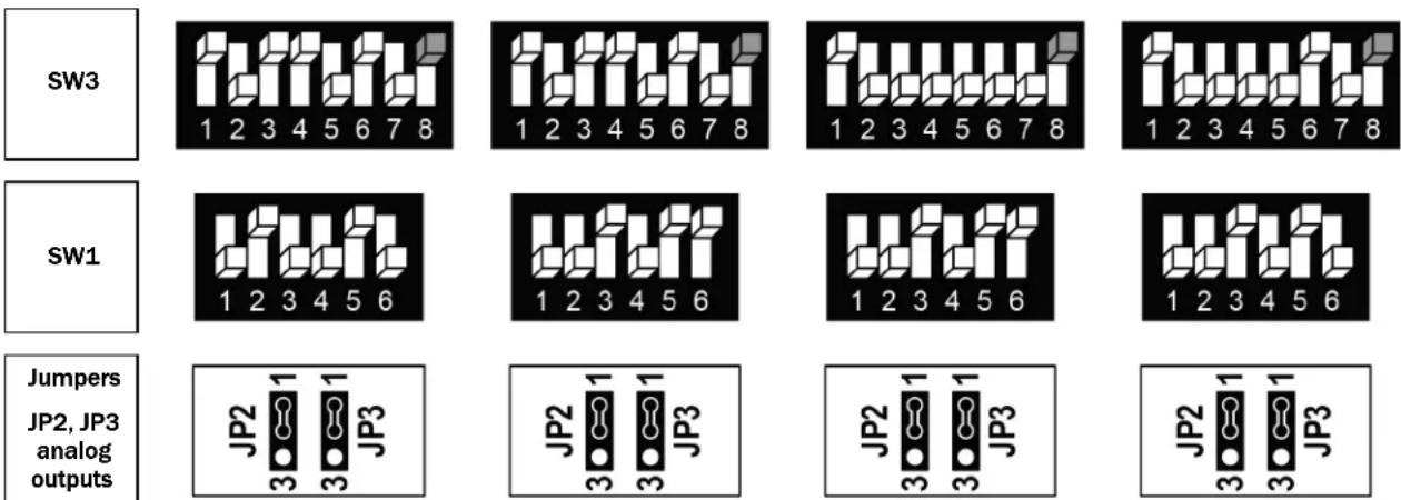
(1) SW3.1, SW3.2 - Fan speeds:
2 speeds (Low and High):
3 speeds (Low, Med., and High):
SW3.1 = OFF, SW3.2 = ON
SW3.1 = OFF, SW3.2 = OFF
(2) SW3.4 - HP (Heat pump): HC (not heat pump):
ON = Heat pump active in cool, OFF = Heat pump active in heat
ON = Electrical heater, OFF = Oil/Gas heater (no fan)
(3) SW3.5 - Compressor delay:
ON = Disable, OFF = Enable
(4) SW1.3 - Dehumidification:
ON = Use dehumidifier, OFF = Use reheat for dehumidification
(5) SW1.6 - Terminal 12 operation:
ON = Economizer
OFF = Fan Medium (3 speeds) / Terminal not in use (2 speeds)
Important: Economizer will not work in 3 fan speeds configuration.
See drawing for DIP switch and jumper locations (page 24).
Fan VFS, PID valves: 0-10 Vdc, 0.5 mA Not isolated
Control - Fan on/off, Heat elements, Cool/Heat valves, Economizer: 24 Vac, 0.5A max
Wiring and DIP switch/jumper configurations 20 to 23 - FC systems - 2-pipe
| Outputs | Config. 20:2-Pipe, 1/2/3 Speeds fan^(1) | Config. 21:2-Pipe, 1/2/3 Speeds fan^(1) , Cool/Heat PID | Config. 22:2-Pipe, Fan VFS | Config. 23:2-Pipe, Fan VFS,Cool/Heat PID |
| 11 | Fan high | Fan high | X | X |
| 12 | Fan medium(or Economizer^(5) ) | Fan medium(or Economizer^(5) ) | Economizer^(5) (option - SW1.6 ON) | Economizer^(5) (option - SW1.6 ON) |
| 13 | Fan low | Fan low | X | X |
| 14 | Heat element^(2) (2nd stage heat) | Heat element^(2) (2nd stage heat) | Heat element^(2) (2nd stage heat) | Heat element^(2) (2nd stage heat) |
| 15 | Cool/heat valve^(3) | Cool valve PID^(3) | Cool/heat valve^(3) | Cool valve PID^(3) |
| 16 | X | X | Fan VFS | Fan VFS |



(1) SW3.1, SW3.2 = Fan speeds:
1 Speed (Low):
2 Speeds (Low and High):
3 Speeds (Low, Medium and High):
SW3.1 ON, SW3.2 OFF
SW3.1 OFF, SW3.2 ON
SW3.1 OFF, SW3.2 OFF
2) SW3.4 = 2nd heating stage:
ON - Enable
OFF - Disable
(3) SW3.5 = Chilled beam option:
ON - Enable chilled beam (fan will not run with cooling)
(4) SW1.3 = Dehumidification:
ON - Use dehumidifier
OFF - Use reheat for dehumidification
(5) SW1.6 = Terminal 12 operation:
ON - Economizer
OFF - Fan Med. (3 Speeds) / Terminal not in use (1/2 Speeds/VFS)
Important: Economizer will not work in 3 fan speeds configuration
See drawing for DIP switch and jumper locations (page 24).
Fan VFS, PID valves: 0-10 Vdc, 0.5 mA Not isolated
Control - Fan on/off, Heat elements, Cool/Heat valves, Economizer: 24 Vac, 0.5A max
Wiring and DIP switch/jumper configurations 24 to 27 - FC systems - 4-pipe
| Outputs | Config. 24:4-Pipe, Fan VFS | Config. 25:4-Pipe, 1/2/3 Speeds fan^(1) , Heat valve PID | Config. 26:4-Pipe, Fan VFS, Heat valve PID | Config. 274-Pipe, Fan VFS, Cool valve PID |
| 11 | Fan high | Fan high | X | X |
| 12 | Fan medium(or Economizer^(5) ) | Fan medium(or Economizer^(5) ) | Economizer^(5) (option - SW1.6 ON) | Economizer^(5) (option - SW1.6 ON) |
| 13 | Fan low | Fan low | X | X |
| 14 | Heat element(2nd stage heat) | Heat element(2nd stage heat) | Heat element(2nd stage heat) | Heat element(2nd stage heat) |
| 15 | Cool/Heat valve^(3) | Cool/Heat valve PID^(3) | Cool/Heat valve^(3) | Cool/Heat valve PID^(3) |
| 16 | Humidifier | Humidifier | Fan VFS | Fan VFS |

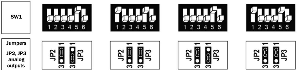
(1) SW3.1, SW3.2 = Fan speeds:
1 Speed (Low):
2 Speeds (Low and High):
3 Speeds (Low, Medium and High):
SW3.1 ON, SW3.2 OFF
SW3.1 OFF, SW3.2 ON
SW3.1 OFF, SW3.2 OFF
2) SW3.4 = 2nd heating stage:
ON - Enable
OFF - Disable
(3) SW3.5 = Chilled beam option:
ON - Enable chilled beam (fan will not run with cooling)
(4) SW1.3 = Dehumidification:
ON - Use dehumidifier
OFF - Use reheat for dehumidification
(5) SW1.6 = Terminal 12 operation:
ON - Economizer
OFF - Fan Med. (3 Speeds) / Terminal not in use (1/2 Speeds/VFS)
Important: Economizer will not work in 3 fan speeds configuration
See drawing for DIP switch and jumper locations (page 24).
Fan VFS, PID valves: 0-10 Vdc, 0.5 mA Not isolated
Control - Fan on/off, Heat elements, Cool/Heat valves, Economizer: 24 Vac, 0.5A max
Wiring and DIP switch/jumper config 28 to 30 - FC systems - 4-pipe
with Dehumidifier, w/wo Humidifier
| Outputs | Config. 28:4-Pipe, Fan VFS | Config. 29:4-Pipe, 1/2/3 Speeds fan^(1) , Heat valve PID | Config. 30:4-Pipe, Fan VFS, Heat valve PID |
| 11 | Fan high | Fan high | X |
| 12 | Fan medium(or Economizer^(5) ) | Fan medium(or Economizer^(5) ) | Economizer^(5) (option - SW1.6 ON) |
| 13 | Fan low | Fan low | X |
| 14 | Cool/Heat valve^(3) | Heat element^(2) (2nd stage heat) | Cool/Heat valve^(3) |
| 15 | Humidifier | Cool/Heat valve PID ^(3) | Fan VFS |
| 16 | Dehumidifier | Dehumidifier(4)(option - See SW1.3) | Dehumidifier |
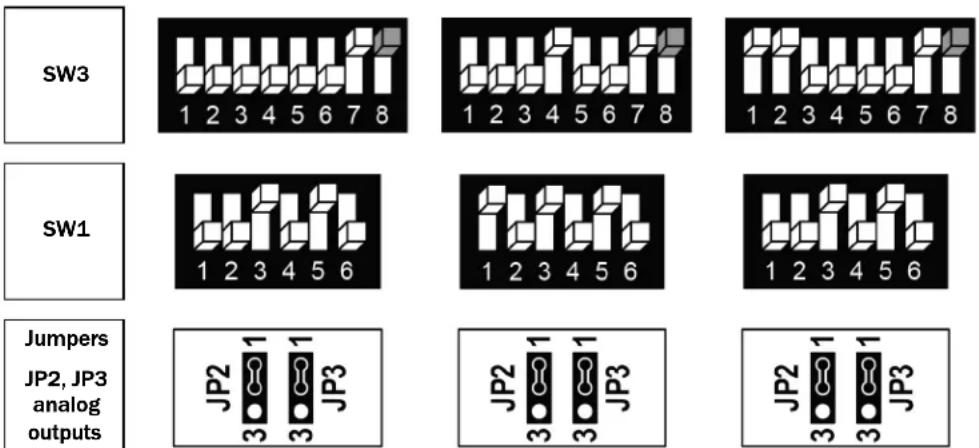
(1) SW3.1, SW3.2 = Fan speeds:
1 Speed (Low):
SW3.1 ON, SW3.2 OFF
2 Speeds (Low and High):
SW3.1 OFF, SW3.2 ON
3 Speeds (Low, Medium and High):
SW3.1 OFF, SW3.2 OFF
2) SW3.4 = 2nd heating stage:
ON - Enable
OFF - Disable
(3) SW3.5 = Chilled beam option:
ON - Enable chilled beam (fan will not run with cooling)
(4) SW1.3 = Dehumidification:
ON - Use dehumidifier
OFF - Use reheat for dehumidification
(5) SW1.6 = Terminal 12 operation:
ON - Economizer
OFF - Fan Med. (3 Speeds) / Terminal not in use (1/2 Speeds/VFS)
Important: Economizer will not work in 3 fan speeds configuration
See drawing for DIP switch and jumper locations (page 24).
Fan VFS, PID valves, Hum., Dehum.: 0-10VDC, 0.5mA Not isolated
Control - Fan on/of, Heat elements, Cool/Heat valves, Economizer: 24VAC, 0.5A max.
Wiring and DIP switch/jumper config 31 to 34 - FC systems - 4-pipe
| Outputs | Config. 31:4-Pipe, 1/2/3 Speeds fan(1) | Config. 32:4-Pipe, 1/2/3 Speeds fan(1), Floor heating | Config. 33:4-Pipe, 1/2/3 Speeds fan(1), Cool valve PID | Config. 34:4-Pipe, 1/2/3 Speeds fan(1), Cool valve PID, Floor heating |
| 11 | Fan high | Fan high | Fan high | Fan high |
| 12 | Fan medium (or Economizer^(5) ) | Fan medium (or Economizer^(5) ) | Fan medium (or Economizer^(5) ) | Fan medium (or Economizer^(5) ) |
| 13 | Fan low | Fan low | Fan low | Fan low |
| 14 | Heat element^(2) (2nd stage heat) | Floor heating (1st stage heat-no fan) | Heat element^(2) (2nd stage heat) | Floor heating (1st stage heat-no fan) |
| 15 | Cool valve^(3) | Cool valve^(3) | Cool valve PID^(3) | Cool valve PID^(3) |
| 16 | Heat valve (1st stage heat) | Heat valve (2nd stage heat) | Heat valve (1st stage heat) | Heat valve (2nd stage heat) |



(1) SW3.1, SW3.2 = Fan speeds:
1 Speed (Low):
SW3.1 ON, SW3.2 OFF
2 Speeds (Low and High):
SW3.1 OFF, SW3.2 ON
3 Speeds (Low, Medium and High):
SW3.1 OFF, SW3.2 OFF
^2) SW3.4 = 2nd heating stage:
ON - Enable
OFF - Disable
(3) SW3.5 = Chilled beam option:
ON - Enable chilled beam (fan will not run with cooling)
(4) SW1.3 = Dehumidification:
ON - Use dehumidifier
OFF - Use reheat for dehumidification
(5) SW1.6 = Terminal 12 operation:
ON - Economizer
OFF - Fan Med. (3 Speeds) / Terminal not in use (1/2 Speeds/VFS)
Important: Economizer will not work in 3 fan speeds configuration
See drawing for DIP switch and jumper locations (page 24).
Fan VFS, PID valves: 0-10VDC, 0.5mA Not isolated
Control - Fan on/of, Heat elements, Cool/Heat valves, Economizer: 24VAC, 0.5A max.
Wiring and DIP switch/jumper config 35 to 38 - FC systems - 4-pipe
| Outputs | Config. 35:4-Pipe, Fan VFS | Config. 36:4-Pipe, 1/2/3 Speeds fan(1), Heat valve PID | Config. 37:4-Pipe, Fan VFS, Heat valve PID | Config. 38:4-Pipe, Fan VFS, Cool valve PID |
| 11 | X | Fan high | X | X |
| 12 | Economizer ^(5) (option - SW1.6 ON) | Fan medium (or Economizer ^(5) ) | Economizer ^(5) (option - SW1.6 ON) | Economizer ^(5) (option - SW1.6 ON) |
| 13 | X | Fan low | X | X |
| 14 | Heat valve | Heat element ^(2) (2nd stage heat) | Cool valve ^(3) | Heat valve |
| 15 | Cool valve ^(3) | Cool valve ^(3) | Heat valve PID | Cool valve PID ^(3) |
| 16 | Fan VFS | Heat valve PID(1st stage heat) | Fan VFS | Fan VFS |

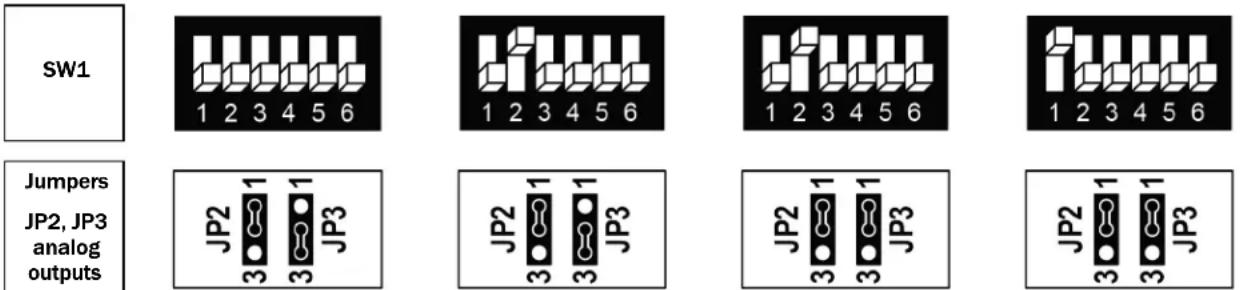
(1) SW3.1, SW3.2 = Fan speeds:
1 Speed (Low):
2 Speeds (Low and High):
3 Speeds (Low, Medium and High):
SW3.1 ON, SW3.2 OFF
SW3.1 OFF, SW3.2 ON
SW3.1 OFF, SW3.2 OFF
2) SW3.4 = 2nd heating stage:
ON - Enable
OFF - Disable
(3) SW3.5 = Chilled beam option:
ON - Enable chilled beam (fan will not run with cooling)
(4) SW1.3 = Dehumidification:
ON - Use dehumidifier
OFF - Use reheat for dehumidification
(5) SW1.6 = Terminal 12 operation:
ON - Economizer
OFF - Fan Med. (3 Speeds) / Terminal not in use (1/2 Speeds/VFS)
Important: Economizer will not work in 3 fan speeds configuration
See drawing for DIP switch and jumper locations (page 24).
Fan VFS, PID valves: 0-10VDC, 0.5mA Not isolated
Control - Fan on/of, Heat elements, Cool/Heat valves, Economizer: 24VAC, 0.5A max.
Wiring and DIP switch/jumper configuration 39 - FC systems - 4-pipe
| Outputs | Config. 39:4-Pipe, 1/2/3 Speeds fan(1), Heat valve PID, Cool valve PID |
| 11 | Fan high |
| 12 | Fan medium (or Economizer ^(5) ) |
| 13 | Fan low |
| 14 | Heat element ^(2) (2nd stage heat) |
| 15 | Cool valve PID ^(3) |
| 16 | Heat valve PID(1st stage heat) |
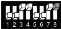
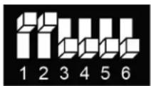
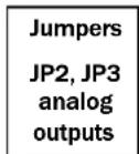
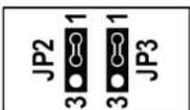
(1) SW3.1, SW3.2 = Fan speeds:
1 Speed (Low): SW3.1 ON, SW3.2 OFF
2 Speeds (Low and High): SW3.1 OFF, SW3.2 ON
3 Speeds (Low, Medium and High): SW3.1 OFF, SW3.2 OFF
2) SW3.4 = 2nd heating stage:
ON - Enable OFF - Disable
(3) SW3.5 = Chilled beam option:
ON - Enable chilled beam (fan will not run with cooling)
(4) SW1.3 = Dehumidification:
ON - Use dehumidifier OFF - Use reheat for dehumidification
(5) SW1.6 = Terminal 12 operation:
ON – Economizer OFF – Fan Med. (3 Speeds) / Terminal not in use (1/2 Speeds/VFS) Important: Economizer will not work in 3 fan speeds configuration
See drawing for DIP switch and jumper locations (page 24).
PID valves: 0-10VDC, 0.5mA Not isolated
Control - Fan on/of, Heat elements, Cool/Heat valves, Economizer: 24VAC, 0.5A max.
Wiring and DIP switch/jumper config 40 to 41 - FC systems - 4-pipe
with Reheat for dehumidification, without Humidifier
| Outputs | Config. 40:4-Pipe, 1/2/3 Speeds fan(1), Heat valve PID | Config. 41:4-Pipe, Fan VFS, Cool valve PID |
| 11 | Fan high | Fan high |
| 12 | Fan medium (or Economizer^(5) ) | Fan medium (or Economizer^(5) ) |
| 13 | Fan low | Fan low |
| 14 | Heat element^(2) (2nd stage heat) | Heat element^(2) (2nd stage heat) |
| 15 | Cool valve^(3) | Cool valve PID^(3) |
| 16 | Heat valve | Heat valve |
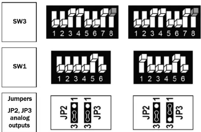
(1) SW3.1, SW3.2 = Fan speeds:
1 Speed (Low): SW3.1 ON, SW3.2 OFF
2 Speeds (Low and High): SW3.1 OFF, SW3.2 ON
3 Speeds (Low, Medium and High): SW3.1 OFF, SW3.2 OFF
^2) SW3.4 = 2nd heating stage:
ON - Enable
OFF - Disable
(3) SW3.5 = Chilled beam option:
ON - Enable chilled beam (fan will not run with cooling)
(4) SW1.3 = Dehumidification:
ON - Use dehumidifier
OFF - Use reheat for dehumidification
(5) SW1.6 = Terminal 12 operation:
ON - Economizer
OFF - Fan Med. (3 Speeds) / Terminal not in use (1/2 Speeds/VFS)
Important: Economizer will not work in 3 fan speeds configuration
See drawing for DIP switch and jumper locations (page 24).
PID valves: 0-10VDC, 0.5mA Not isolated
Control - Fan on/of, Heat elements, Cool/Heat valves, Economizer: 24VAC, 0.5A max.
Wiring and DIP switch/jumper config 42 to 44 - FC systems - 4-pipe
with Humidifier, without Reheat for dehumidification
| Outputs | Config. 42:4-Pipe, 1/2/3 Speeds fan^(1) , Humidifier | Config. 43:4-Pipe, 1/2/3 Speeds fan^(1) , Cool valve PID, Humidifier | Config. 44:4-Pipe, 1/2/3 Speeds fan^(1) , Heat valve PID, Humidifier |
| 11 | Fan high | Fan high | Fan high |
| 12 | Fan medium (or Economizer^(5) ) | Fan medium (or Economizer^(5) ) | Fan medium (or Economizer^(5) ) |
| 13 | Fan low | Fan low | Fan low |
| 14 | Heat valve | Heat valve | Cool valve^(3) |
| 15 | Cool valve^(3) | Cool valve PID^(3) | Heat valve PID |
| 16 | Humidifier | Humidifier | Humidifier |
| Outputs |
| 11 |
| 12 |
| 13 |
| 14 |
| 15 |
| 16 |
| Config. 42:4-Plpe, 1/2/3 Speeds fan(1), Humidifier |
| Fan high |
| Fan medium (or Economizer(5)) |
| Fan low |
| Heat valve |
| Cool valve(3) |
| Humidifier |
| Config. 43:4-Pipe, 1/2/3 Speeds fan(1), Cool valve PID, Humidifier |
| Fan high |
| Fan medium (or Economizer(5)) |
| Fan low |
| Heat valve |
| Cool valve PID(3) |
| Humidifier |
| Config. 44:4-Pipe, 1/2/3 Speeds fan(1), Heat valve PID, Humidifier |
| Fan high |
| Fan medium (or Economizer(5)) |
| Fan low |
| Cool valve(3) |
| Heat valve PID |
| Humidifier |
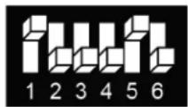
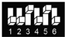
| SW3 |
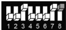
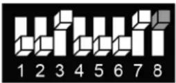
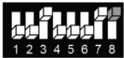
| SW1 |
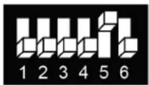
| Jumpers |
| JP2, JP3 analog outputs |
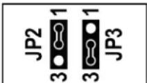
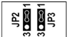
(1) SW3.1, SW3.2 = Fan speeds:
1 Speed (Low):
SW3.1 ON, SW3.2 OFF
2 Speeds (Low and High):
SW3.1 OFF, SW3.2 ON
3 Speeds (Low, Medium and High):
SW3.1 OFF, SW3.2 OFF
^2) SW3.4 = 2nd heating stage:
ON - Enable
OFF - Disable
(3) SW3.5 = Chilled beam option:
ON - Enable chilled beam (fan will not run with cooling)
(4) SW1.3 = Dehumidification:
ON - Use dehumidifier
OFF - Use reheat for dehumidification
(5) SW1.6 = Terminal 12 operation:
ON - Economizer
OFF - Fan Med. (3 Speeds) / Terminal not in use (1/2 Speeds/VFS)
Important: Economizer will not work in 3 fan speeds configuration
See drawing for DIP switch and jumper locations (page 24).
PID valves, Humidifier: 0-10VDC, 0.5mA Not isolated
Control - Fan on/of, Heat elements, Cool/Heat valves, Economizer: 24VAC, 0.5A max.
Wiring and DIP switch/jumper config 45 to 47 - FC systems - 4-pipe
with Dehumidifier
| Outputs | Config. 45:4-Pipe, 1/2/3 Speeds fan^(1) , Dehumidifier | Config. 46:4-Pipe, 1/2/3 Speeds fan^(1) , Cool valve PID, Dehumidifier | Config. 47:4-Pipe, 1/2/3 Speeds fan^(1) , Heat valve PID, Dehumidifier |
| 11 | Fan high | Fan high | Fan high |
| 12 | Fan medium (or Economizer^(5) ) | Fan medium (or Economizer^(5) ) | Fan medium (or Economizer^(5) ) |
| 13 | Fan low | Fan low | Fan low |
| 14 | Heat valve | Heat valve | Cool valve^(3) |
| 15 | Cool valve^(3) | Cool valve PID^(3) | Heat valve PID |
| 16 | Dehumidifier | Dehumidifier | Dehumidifier |
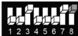
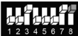
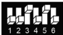
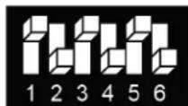
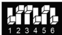
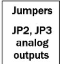
(1) SW3.1, SW3.2 = Fan speeds:
1 Speed (Low):
SW3.1 ON, SW3.2 OFF
2 Speeds (Low and High):
SW3.1 OFF, SW3.2 ON
3 Speeds (Low, Medium and High):
SW3.1 OFF, SW3.2 OFF
2) SW3.4 = 2nd heating stage:
ON - Enable
OFF - Disable
(3) SW3.5 = Chilled beam option:
ON - Enable chilled beam (fan will not run with cooling)
(4) SW1.3 = Dehumidification:
ON - Use dehumidifier
OFF - Use reheat for dehumidification
(5) SW1.6 = Terminal 12 operation:
ON - Economizer
OFF - Fan Med. (3 Speeds) / Terminal not in use (1/2 Speeds/VFS)
Important: Economizer will not work in 3 fan speeds configuration
See drawing for DIP switch and jumper locations (page 24).
PID valves, Humidifier: 0-10VDC, 0.5mA Not isolated
Control - Fan on/of, Heat elements, Cool/Heat valves, Economizer: 24VAC, 0.5A max.
Technician Settings
Enter Technician Settings mode:
1 Adjust the setpoint temperature to 10^ C or 50^ F.
2 Press and hold the [C/F] button for 10 seconds to enter Technician Settings mode. "P01" will appear on the display.
View objects and make adjustments:
• Use the [Mode] button to step forward between different settings.
• Use the [Fan] button to step backward between different settings.
- Press the [On/Off] button to exit Technician Settings and return to normal display.
- If no button is pressed for 60 seconds, the thermostat will automatically exit Technician Settings and return to normal display.
- Use the [+] or [-] button to make adjustments when required.
Technician Settings P01 to P03
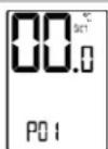
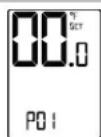
P01 - Offset for temperature readings calibration
Range: -6...+6°C / -9...+9°F.
Default: 0^ C / 0^ F.
Note: The offset will influence both internal or external sensors.
Offset for temperature calibration
(°C)
(°F)
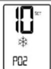
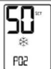
P02 - Setpoint limit for cooling
Range: 5...35°C / 41...95°F.
Default: 10^ C / 50^ F.
Note: The thermostat will stop cooling regardless of the user's setpoint
Set point limit for cooling
(°C)
(°F)
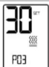
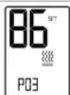
P03 - Setpoint limit for heating
Range: 5...35°C / 41...95°F.
Default: 30^ C / 86^ F.
Note: The thermostat will stop heating regardless of the user's setpoint
Setpoint limit for heating
(°C)
(°F)
Technician Settings P04 to P07
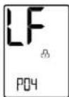
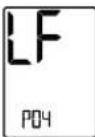
P04 - Enable/Disable the option to lock the [Fan] button
| “LF” + ” [Fan] button can be locked | LP P04 | LP P04 |
| “LF” only[Fan] button cannot be locked | [Fan] Can be locked | [Fan] Cannot be locked |
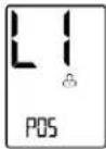
P05 - Enable/Disable the option to lock the [Mode] button
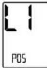
| “L1” + ”[Mode] button can be locked | |
| “L1” only [Mode] button cannot be locked | |
| Note: When enabled, press and hold [-] and [Fan] buttons for 7 seconds to unlock or relock the buttons. |
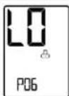
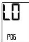
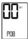
P06 - Enable/Disable the option to lock the [On/Off] button
| “LO” + ” | [On/Off] button can be locked | |
| “00” only | [On/Off] button cannot be locked | |
| Note: When enabled, press and hold both [-] and [Fan] buttons for 7 seconds to unlock or relock the buttons. | ||
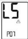
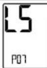
P07 - Enable/Disable the option to lock the ▲ or ▼ button (SET)
| “LS” + ” | [+] or [-] button can be locked | |
| “LS” only | [+] or [-] button cannot be locked | |
| Note: When enabled, press and hold both [-] and [Fan] buttons for 7 seconds to unlock or relock the buttons. | ||
P04-P07 Note:
When the option to lock one or more buttons is enabled, these buttons will be automatically locked when leaving technician settings and returning to normal display.
In normal display, press and hold the [Mode] button for 7 seconds to unlock/relock these buttons.
Technician Settings P08 to P10
P08 - Functionality of T1 terminals
| "00" - T1 terminals are not in use |
| "01" - External sensor |
| "02"- T3 Soft start in heat sensor (FC) * or De-icing in cool (AC) ** |
| "03" - Door switch |
| "04" - Key tag |
| "05" - T Economizer(DIP switch SW2.6 must be ON) |
| * In heating mode, the fan will not start before there is hot water in the coil. |
| Note: To view T3 on the BACnet Thermostat, see Technician Settings P84. |
| ** Allow de-icing operation of indoor coil in cooling. |
T1 terminals
Not in use
T1 sensor (External sensor)
T3 Soft start in heat sensor (FC) or De-icing in cool sensor (AC)
Door switch
Key tag
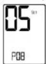
T Economizer
P09 - Functionality of IN1,0 terminals
| "00" - IN1,0 terminals are not in use |
| "01" - *T2 (Change over sensor) (FC) or De-icing in heat (AC) |
| "02" - **T3 (Soft start in heat sensor) (FC) or De-icing in cool (AC) |
| "03" - | Window contact - Remote On/Off switch |
| "04" - | Window contact - Remote Economy switch |
| "05" - ***External Passive Infrared detector |
| * In 2-Pipe system, T2 will sense the water temperature in the pipe in order to select/allow effective system mode. |
| Note: To view T2 on the BACnet Thermostat, see Technician Settings P83. |
| ** Where T1 terminals are used for external sensor, the IN1,0 terminals can be used for T3 sensor. |
| Note: To view T3 on the BACnet Thermostat, see Technician Settings P84. |
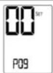
"IN1,0" terminals Not in use
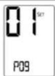
T2 change over sensor (FC) or Deicing in heat (AC)
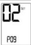
**T3 Soft start in heat sensor (FC) or Deicing in cool sensor (AC)
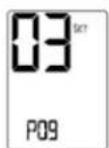
Window contact Remote On/Off switch
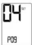
Window contact Remote Economy switch
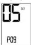
External
PIR sensor
P10 - Window contact (terminals IN1,0) polarity
| "01" - Normally open |
| "00" - Normally closed |
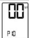
Window contact Normally close
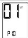
Window contact Normally open
Technician Settings P11 to P15
P11 - Window contact delay time
Range: 0...999 seconds.
Default: 600 seconds.
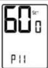
Window contact delay time (sec.)
P12 - Door switch (terminals T1,0) polarity
"01" - Normally open
"00" - Normally closed
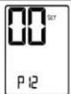
Door switch Normally close
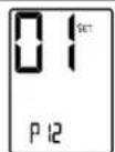
Door switch Normally open
P13 - Door switch delay time
Range: 0...999 seconds.
Default: 180 seconds.
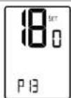
Door switch delay time (sec.)
P14 - Enable/Disable Auto change over mode
"00" - Disable Auto change over mode
"01" - Enable Auto change over mode
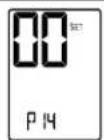
Disable Auto mode
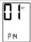
Enable Auto mode
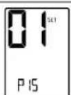
P15 - Motion sensor logic (PIR)
"00" - Thermostat turns off when unoccupied and back on when re-occupied.
"01" - Thermostat turns off when unoccupied and remains off when re-occupied.
"02" - Thermostat uses economy setpoints when unoccupied.
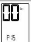
Unocc. - Off Re-occ. - On
Unocc. - Off Re-occ. - Off
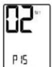
Economy set points
Technician Settings P16 to P25
P16 - Enable/Disable Motion sensor
"00" - Disable
"01" - Enable
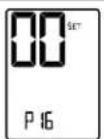
Disable
occ. sensor
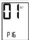
Enable
occ. sensor
P17 - PIR (Motion sensor) delay time before switching to unoccupied mode (ON delay)
Range: 0...900 minutes
Default: 20 minutes
PIR ON delay (minutes)
P18 - Door switch or key tag configuration
"00" - Switch On/Off by door switch or key tag
"01" - Changing the setpoint temperature
"02" - Switching fan speed to Low
Switch
On or Off
Change set-points
Switch to fan low
P19 - PIR (Motion sensor) polarity
"00" - Normally open
"01" - Normally closed
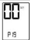
PIR PIR
Normally open Normally close
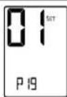
PIR
Normally close
P25 - Economy setpoint for cooling
Range: 5...35°C / 41...95°F
Default: 30°C / 86°F
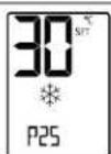
EC set point in cooling
(°C) (°F)
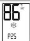
(°F)
Technician Settings P26 to P30
P26 - Economy setpoint for heating
Range: 5...35°C / 41...95°F
Default: 10^ / 50^
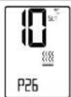
EC set point in heating
(°C) (°F)
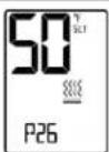
(°F)
P27 - On-delay time on-delay between heating stages
Range: 0....600 seconds
Default: 5 seconds
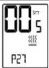
On delay
heating stages
P28 - Off-delay time between heating stages
Range: 0....600 seconds
Default: 1 second
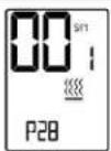
Off delay
heating stages
P29 - LCD Backlight ON or OFF
"00" - LCD Backlight ON
"01" - LCD Backlight OFF
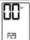
Backlight ON
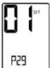
Backlight OFF
P30 - Beeper ON or OFF
"01" - Beeper ON
"00" - Beeper OFF
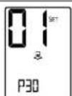
Beeper ON
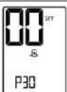
Beeper
OFF
Technician Settings P31 to P34
P31 - P34
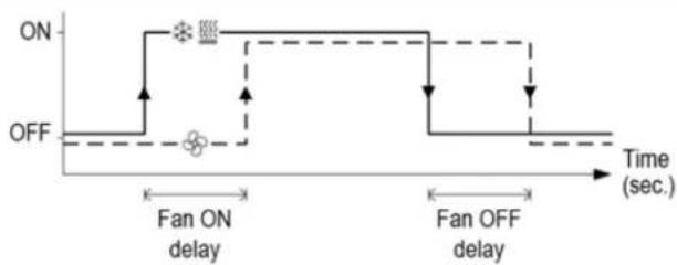
Fan on/off delay
with fan on demand (auto fan) active.

flowchart
graph TD
    A["ON"] --> B["Fan ON delay"]
    B --> C["OFF"]
    C --> D["Fan OFF delay"]
    D --> E["Time (sec.)"]
    style A fill:#f9f,stroke:#333
    style B fill:#ccf,stroke:#333
    style C fill:#cfc,stroke:#333
    style D fill:#fcc,stroke:#333
    style E fill:#ffc,stroke:#333
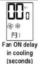
P31 - Fan ON delay in cooling (FC only)
Range: 0...120 seconds
Default: 0 seconds (no delay)
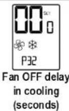
P32 - Fan OFF delay in cooling
Range: 0...120 seconds
Default: 0 seconds (no delay)
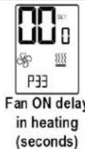
P33 - Fan ON delay in heating (FC only)
Range: 0...120 seconds
Default: 0 seconds (no delay)
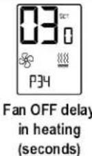
P34 - Fan OFF delay in heating
Range: 0...120 seconds
Default: 30 seconds
Technician Settings P35 to P42
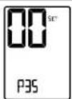
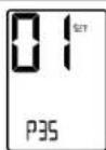
P35 - Enable/Disable Freeze protection
"00" - Disable Freeze protection
"01" - Enable Freeze protection
Note: If enabled, freeze protection will start when the thermostat is either ON or OFF and regardless of the current system mode.
Disable freeze protection
Enable freeze protection
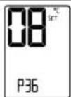
P36 - Freeze protection cut-in setpoint
Range: 8...15°C / 46...59°F
Default: 8^ C / 46^ F
The room ambient temperature which will trigger Heating ON.
Range: 10...17°C / 50...63°F
Default: 10°C / 50°F
The room ambient temperature which will switch the Heating back OFF.
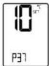
Freeze protection cut-out set point
(°C) (°F)
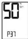
(°F)
P40 - View filter counter (hours) - Read only
Range: 0...999 hours
The filter counter is related to Fan running time.
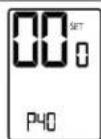
View filter
Counter (hours)
P41 - Reset filter time
Press the [+] button to reset the filter counter.
The display will change from "00" to "01" and back to "00".
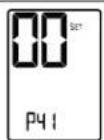
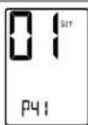
Reset filter counter
P42 - Adjust filter alarm delay time counter (hours)
Range: 0...999 hours
Default: 0 hours (0 = Disable)
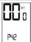
Adjust filter alarm delay time (hours)
Technician Settings P43 to P44
P43 - P44
Soft start in heat
with fan on demand (auto fan) active.
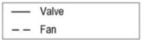
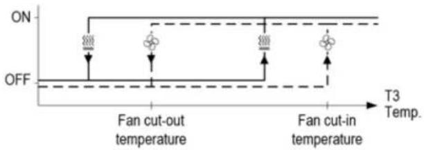
P43 - Soft start in heat - cut-in temperature (FC only)
The fan will not start before the temperature on T3 sensor reaches the cut-in temperature.
See Technician Settings P08/P09.
Range: 14...37°C / 57...99°F
Default: 36°C / 97°F
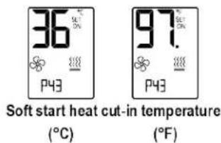
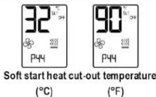
P44 - Soft start in heat - cut-out temperature (FC only)
The fan will stop if the temperature on T3 sensor drops below the cut-out temperature.
See Technician Settings P08/P09.
Range: 12...35°C / 54...95°F
Default: 32°C / 90°F
Technician Settings P45 to P46
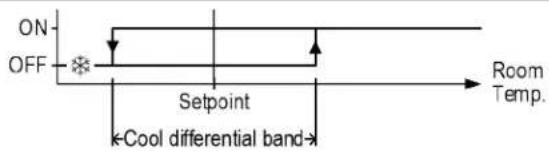
P45 - P46
Cool differential band / offset
(with cool differential band offset = 0)
— Compressor / Valve
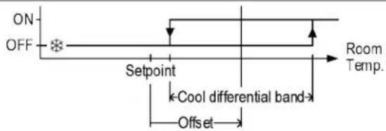
P45 - P46
Cool differential band / offset
(with cool differential band offset ≠ 0)
— Compressor / Valve
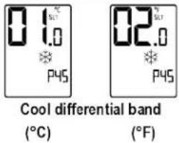
P45 - Cool differential band
Range: 0.5...5°C / 1...10°F
Default: 1°C / 2°F
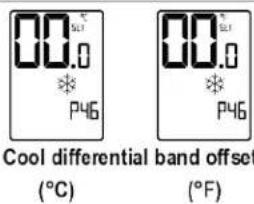
P46 - Cool differential band offset
Range: -5...+5°C / -9...+9°F
Default: 0^ C / 0^ F
Technician Settings P47 to P48
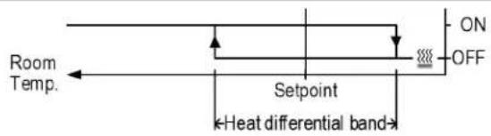
P47-48
Heat differential band / offset
(with heat differential band offset = 0)

Compressor / Valve
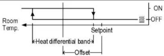
P47-48
Heat differential band / offset
(with heat differential band offset 0 )

Compressor / Valve
P47 - Heat differential band
Range: 0.5...5°C / 1...10°F
Default: 1°C / 2°F
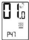
(°C)
Heat differential band
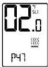
(°F)
P48 - Heat differential band offset
Range: -5...+5°C / -9...+9°F
Default: 0^ C / 0^ F
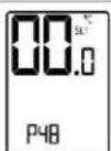
Heat differential band offset
(°C)
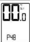
(°F)
Technician Settings P49 to P51
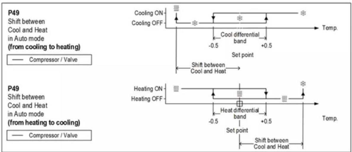
P49 - Shift between Cool and Heat in Auto change over mode
Range: 0...10°C / 0...20°F
Default: 2°C / 4°F
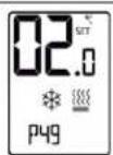
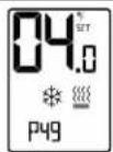
Shift between Cool & Heat in Auto mode
(°C)
(°F)
P50 - Shift between Cooling stages (AC only)
Range: 0...10°C / 0...20°F
Default: 2^ / 4^
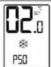
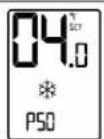
Shift between cooling stages
(°C)
(°F)
P51 - Shift between Heating stages
Range: 0...49°C / 0...98°F
Default: 2^ / 4^
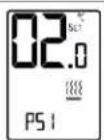
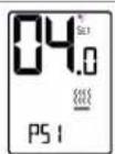
Shift between heating stages
(°C)
(°F)
Technician Settings P52 to P57
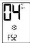
P52 - Cool valve proportional band (FC only)
Range: 2...10°C / 4...20°F
Default: 2°C / 4°F
0-10V Valve opening from fully closed to fully open.
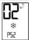
Cool valve proportional band
(°C) (°F)
(°F)
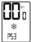
P53 - Cool proportional low limit (FC only)
Range: 0...100%
Default: 0%
Minimum valve opening.
Cool prop. low limit (%)
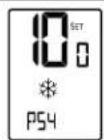
P54 - Cool proportional high limit (FC only)
Range: 0...100%
Default: 100%
Maximum valve opening.
Cool prop.
high limit (%)
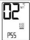
P55 - Heat valve proportional band (FC only)
Range: 2...10°C / 4...20°F
Default: 2°C / 4°F
0-10V Valve opening from fully closed to fully open.
Cool valve proportional band
(°C) (°F)
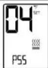
(°F)
P56 - Heat proportional low limit (FC only)
Range: 0...100%
Default: 0%
Minimum valve opening.
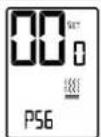
Heat prop. low limit (%)
P57 - Heat proportional high limit (FC only)
Range: 0...100%
Default: 100%
Maximum valve opening.
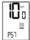
Heat prop.
high limit (%)
Technician Settings P60 to P64
P60
Fan turns ON when the Cool or Heat valve reaches the "Proportional ON percent"
P61
Fan turns OFF when the Cool or Heat valve drops below the "Proportional OFF percent"
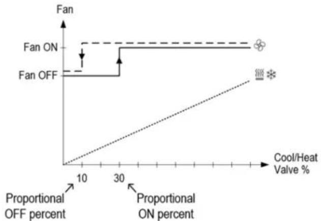
line
| Cool/Heat Valve % | Fan OFF | Fan ON | |---|---|---| | 10 | 0 | 0 | | 30 | 0 | 1 | | 50 | 0 | 1 | The chart displays a stepwise increasing trend for Fan OFF from 0 to 1 as Cool/Heat Valve increases from 10% to 30%, indicating a threshold behavior where higher proportions of the valve increase proportionally. The legend also includes symbols: a star (on) and an asterisk (*) (on).P60 - Proportional ON percent (FC only)
Range: 0...30%
Default: 30%
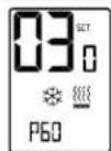
Proportional ON percent (%)
P61 - Proportional OFF percent (FC only)
Range: 0...100%
Default: 100%
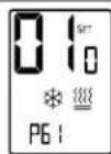
Proportional OFF percent (%)
P63 - Time on-delay between cooling stages (AC only)
Range: 0...600 seconds
Default: 5 seconds
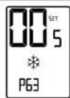
On Delay
cooling stages
P64 - Time off-delay between cooling stages (AC only)
Range: 0...600 seconds
Default: 1 seconds
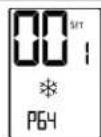
Off Delay
cooling stages
Technician Settings P65 to P70
P65 - Fan VFS proportional band in cooling
Range: 2...10°C / 4...20°F
Default: 2°C / 4°F
0-10V fan speed from off closed to fully running.
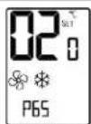
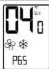
VFS Proportional band in cooling
(°C)
(°F)
P66 - Fan VFS proportional band in heating
Range: 2...10°C / 4...20°F
Default: 2°C / 4°F
0-10V fan speed from off closed to fully running.
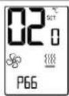
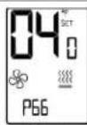
VFS Proportional band in heating
(°C)
(°F)
P67 - Fan VFS Low speed percent in cooling
Range: 0...30%
Default: 20%
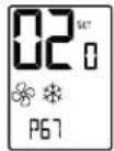
VFS Low % in cooling
P68 - Fan VFS Medium speed percent in cooling
Range: 30...60%
Default: 50%
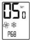
VFS Med % in cooling
P69 - Fan VFS High speed percent in cooling
Range: 60...100%
Default: 90%
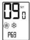
VFS High % in cooling
P70 - Fan VFS Low speed percent in heating
Range: 0...30%
Default: 30%
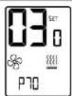
VFS Low % in heating
Technician Settings P71 to P75
P71 - Fan VFS Medium speed percent in heating
Range: 30...60%
Default: 50%
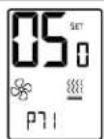
VFS Med % in heating
P72 - Fan VFS High speed percent in heating
Range: 60...100%
Default: 80%
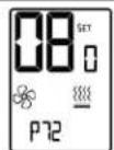
VFS High % in heating
P74
VFS Medium speed differential (display from medium to low)
P75
VFS High speed differential (display from high to medium)
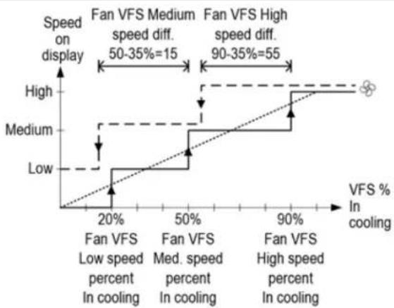
line
| VFS % In cooling | Low speed percent In cooling | Medium speed percent In cooling | High speed percent in cooling | | ---------------- | ----------------------------- | -------------------------------- | ------------------------------ | | 0 | 0 | 0 | 0 | | 20% | 20% | 20% | 20% | | 50% | 50% | 50% | 50% | | 90% | 90% | 90% | 90% |P74 - VFS Medium speed differential
Range: 10...50%
Default: 35
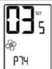
VFS Med speed differential
P75 - VFS High speed differential
Range: 10...50%
Default: 35
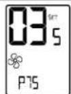
VFS High speed differential
Technician Settings P76 to P79
P76 - Fan VFS Low limit in cooling
Range: 0...100%
Default: 0%
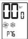
VFS low limit in cooling
P77 - Fan VFS High limit in cooling
Range: 0...100%
Default: 100%
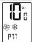
VFS high limit in cooling
P78 - Fan VFS Low limit in heating
Range: 0...100%
Default: 0%
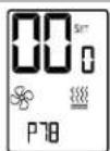
VFS low limit in heating
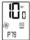
P79 - Fan VFS High limit in heating
Range: 0...100%
Default: 100%
VFS high limit in heating
Technician Settings P83 to P88
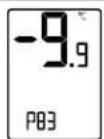
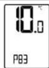
P83 - View T2 temperature sensor readings
Note: If T2 is not connected, -9.9 will appear on display
T2 Sensor
Not connected
T2 Sensor readings (°C)
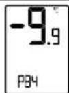
P84 - View T3 temperature sensor readings
Note: If T3 is not connected, -9.9 will appear on display
T3 Sensor T3 Sensor
Not connected readings (°C/°F)
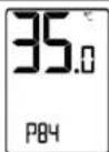
T3 Sensor
adings (°C/°F)
P85 - De-ice in cool - cut-in temperature (AC only)
Range: -9.5...+8°C / 15...46°F
Default: 0^ / 32^
The indoor unit coil temperature in which de-icing will start.
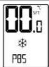
P86 - De-ice in cool - cut-out temperature (AC only)
Range: 2...20°C / 36...68°F
Default: 8°C / 46°F
The indoor unit coil temperature in which de-icing will stop.
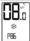
P87 - De-ice in heat time (AC only)
Range: 2...7 Minutes
Default: 5 Minutes
The length of de-icing procedure.
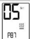
Deice in heat time
P88 - De-ice in heat break time (AC only)
Range: 10...30 Minutes
Default: 25 Minutes
The time interval between de-icing cycles.
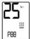
Deice in heat
break time
Technician Settings P89 to P99
P89 - De-ice in heat - cut-in temperature (AC only)
Range: -9.5...+8°C / 15...46°F
Default: 0^ / 32^
The outdoor unit coil temperature in which de-icing will start.
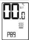
P90 - De-ice in heat - cut-out temperature (AC only)
Range: 2...20°C / 35...68°F
Default: 16°C / 61°F
The outdoor unit coil temperature in which de-icing will stop.
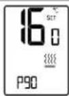
P91 - Compressor delay (AC only)
Range: 0...360 Seconds
Default: 240 Seconds
DIP Switch SW3.5 must be in "OFF" position - compressor delay enabled!
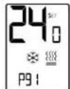
Compressor delay
P98 - Display setpoint only (hide room temperature)
"00" - Display both setpoint and room temperatures
"01" - Display only the setpoint temperature
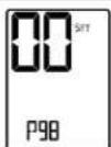
Show room temperature
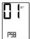
Hide room temperature
P99 - One or Two setpoints (for cool and for heat)
"00" - One setpoint for cooling and heating
"01" - Two setpoints, one for cool and one for heat
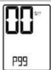
One set point
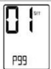
Two set points
Technician Settings P101 to P111
P101 - Screen dimming delay
Range: 0...99 minutes
Default: 5 minutes
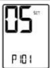
Screen dimming delay
P107 - Weekly program configuration
"00" - Disable weekly program (program parameters will be lost)
"01" - 7 days with the same program
"02" - One program for Monday to Friday and another program for Saturday and Sunday
"03" - One program for Monday to Friday, one for Saturday, and another for Sunday
"04" - 7 days with the different program for each day
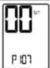
Weekly program configuration
P108 - Weekly program - events per day
"00" - Two different events per day
"01" - Four different events per day
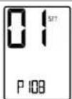
Weekly program events per day
P109 - Weekly program event configuration
"00" - US Program: Event start time, Mode, Fan speed, Setpoints (one or two)
"01" - Eu program: Event start time, Stop time
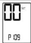
Weekly program event configuration
P111 - PIR Sensitivity
Range: 1...5 (1 - Less sensitive, 5 - More sensitive)
Default: 4
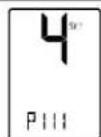
PIR Sensitivity
Technician Settings P114 to P119
| P114 – Cool PID Kp (FC only)Range: 0...100%Default: 100% | 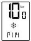 Cool PID Kp Cool PID Kp |
| P115 – Heat PID Kp (FC only)Range: 0...100%Default: 100% | 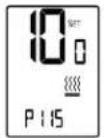 Heat PID Kp Heat PID Kp |
| P116 – Cool PID Ki (FC only)Range: 0...100%Default: 0% | 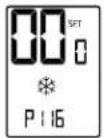 Cool PID Ki Cool PID Ki |
| P117 – Heat PID Ki (FC only)Range: 0...100%Default: 0% | 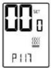 Heat PID Ki Heat PID Ki |
| P118 – Cool PID Kd (FC only)Range: 0...100%Default: 1% | 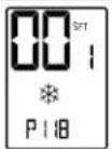 Cool PID Kd Cool PID Kd |
| P119 – Heat PID Kd (FC only)Range: 0...100%Default: 1% | 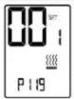 Heat PID Kd Heat PID Kd |
Technician Settings P122 to P188
| P122 - Cool Proportional output threshold time (seconds) (FC only) | |
| Range: 0...100 seconds | 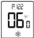 |
| Default: 60 seconds | |
| Cool proportional threshold time | |
| P123 - Heat Proportional output threshold time (seconds) (FC Only) | |
| Range: 0...100 seconds | 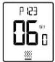 |
| Default: 60 seconds | |
| Heat proportional threshold time | |
| P160 - Minimum compressor ON time (AC only) | |
| Range: 0...20 minutes | 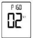 |
| Default: 2 minutes | |
| Minimum compressor ON time | |
| P161 - Minimum compressor OFF time (AC only) | |
| Range: 0...20 minutes | 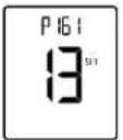 |
| Default: 13 minutes | |
| Minimum compressor OFF time | |
| P170 - Economizer low limit temperature | |
| Range: 9...27°C / 48...80°F | 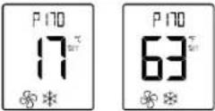 |
| Default: 17°C / 63°F | |
| Economizer low limit temperature (°C) (°F) | |
| P187 - Display or hide humidity reading | |
| “00” - Do not display humidity reading | 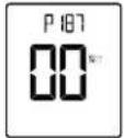 |
| “01” - Display humidity reading | |
| Display or hide humidity readings | |
| P188 - Room temperature limit for disabling dehumidification in unoccupied mode | |
| Range: 10...30°C / 50...85°F | 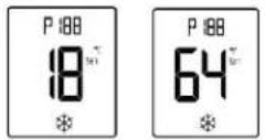 |
| Default: 18°C / 64°F | |
| Temp. for disabling dehum. In unocc mode (°C) (°F) | |
Technician Settings P189 to P195
P189 - Dehumidification cycle in unoccupied mode
Range: 0...600 minutes
Default: 20 minutes
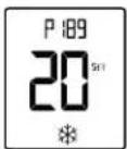
Dehumidification cycle in unocc. mode
P190 - Dehumidification break time in unoccupied mode
Range: 0...900 minutes
Default: 40 minutes
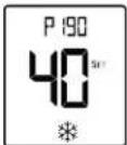
Dehumidification break in unocc. mode
P192 - Temperature setpoint for reheat in unoccupied mode
Range: 10...30°C / 50...86°F
Default: 15°C / 59°F
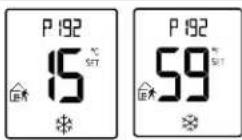
Setpoint for reheat in unocc. mode (°C) (°F)
P193 - Display switching time (between temperature and humidity)
Range: 0...11 seconds
Default: 5 seconds
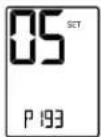
Display switching time Hum./Temp.
P194 - Humidity differential band
Range: 0...10 %RH
Default: 5%RH
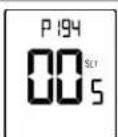
Humidity differential band
P195 - Humidity sensor reading offset
Range: -9...+9 %RH
Default: 0 %RH
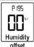
Technician Settings P196 to P200
P196 - Dead zone between humidification and dehumidification
Range: 0...100 %RH
Default: 0 %RH
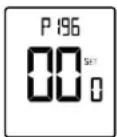
Dead zone
Hum./Dehum.
P197 - Humidity setpoint
Range: 20...100 %RH
Default: 45 %RH
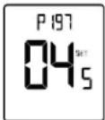
Humidity setpoint
P198 - Not in use
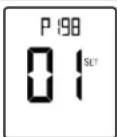
Communication protocol indication
Press the ▲button. The display changes from "00" to "01".
Press the [On/Off] button to restore default settings.
The thermostat turns Off.
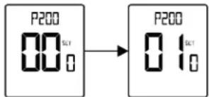
Restore defaults
Press the [On/Off] button or wait 60 seconds to return to normal display.
Alarms and indications
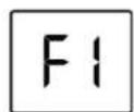
T1 Internal sensor or T1 External sensor fault
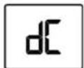
De-icer in cool indication
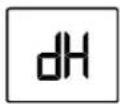
De-icer in heat indication
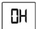
Overheat in heat
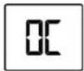
Overheat in cool
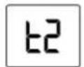
Teconomizer sensor fault
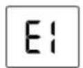
Economy by:
• Window contact - Remote on/off switch
• Window contact - Remote economy switch
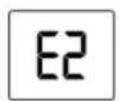
Economy by:
- External PIR
- Communication
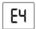
Economy by door switch
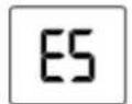
Economy by key-tag
Document revision history
| Date | Topic | Change Description |
| 4/7/20 Installation Up | Updated installation height | |
| Alarms and indicators | Updated Teconomizer sensor fault image | |
| 2/26/20 Cover Updat | ted graphic | |
| MAC address and BACnet Device instance number - In an Analog Network Output microblock | Added subsequent values | |
| 2/18/20 | Operating instructions | Multiple revisions |
| Weekly program Multiple revisions | ||
| Wiring and DIP switch configurations - AC systems - Output 14 | Added (3) to each Config | |
| Technician Settings Multiple revisions | ||
| Alarms and indications Added E1, E2, | E4, and E5 | |
| 9/9/19 | Operating Instructions, P10 | Added AC and FC configurations |
| Operating Instructions, P11 | Changed Remote economy switch settings | |
| Technician Settings, P34 | Changed P11 default from 60 to 600 seconds | |
| Technician Settings, P35 | Changed P17 range from 250 to 900 minutes | |
| 2/18/20 | Operating instructions | Multiple revisions |
| Weekly program | Multiple revisions | |
| Wiring and DIP switch configurations - AC systems - Output 14 | Added (3) to each Config | |
| Technician Settings Multiple revisions | ||
| Alarms and indications Added E1, E2, | E4, and E5 | |
| 9/9/19 | Operating Instructions, P10 | Added AC and FC configurations |
| Operating Instructions, P11 | Changed Remote economy switch settings | |
| Technician Settings, P34 | Changed P11 default from 60 to 600 seconds | |
| Technician Settings, P35 | Changed P17 range from 250 to 900 minutes | |
| 5/22/19 | Technician Settings, P03 | Changed 86c to 30c, changed 30f to 86f |
| 2/21/19 | FC configurations for 2-pipe systems | Changed configurations numbers from 20 through 23 to 10 through 13 |
| FC configurations for 4-pipe systems | Changed configurations numbers from 31 through 39 to 14 through 22 | |
| 2/18/19 | Specifications | Changed Mounting specification description |
| Added CE and C-Tick icons to Compliance specification | ||
| Installation | Changed step B and illustrations | |
| Technician Settings, P122 and P123 | Changed from percent to time (seconds) |

CARRIER CORPORATION ©2020 · Catalog No. 11-808-723-01 · 4/7/2020
- Installation and Operation Guide
- Contents
- Overview
- Technician Settings Index
- Operating Instructions
- Turning the thermostat ON and OFF
- Selecting temperature scale
- Adjusting the Setpoint temperature
- In One setpoint configuration:
- In Two setpoints configuration:
- Selecting system mode
- Selecting fan speed (for 2 and 3 fan speeds configuration)
- Turning Auto fan ON or OFF (fan on demand)
- In 1-speed configuration:
- In 2- and 3-speed configurations:
- Locking the thermostat buttons
- Economy mode
- Freeze Protection
- Economizer
- Indication for the Economizer operation:
- Weekly program
- General
- Program types
- Daily events
- IMPORTANT
- Enabling/Temporarily Disabling/Overriding the program
- Programming procedure
- Exit the programming procedure
- Adjusting the time and day of the week
- Hours
- Minutes
- Days
- Adjusting "EU type" daily programs
- Start time
- Stop time
- Adjusting "US type" daily programs
- System mode and fan speed
- Setpoint
- MAC Address and BACnet Device Instance Number
- MAC Address
- BACnet Device Instance Number
- In the i-Vu® application
- In an Analog Network Output microblock
- Installation
- Installation procedure
- SW4.1 - Without valves control in FC config.
- SW4.2 - Enable/Disable PIR detector
- SW4.3 - Not used
- SW4.4 - End of line resistor (120Ω)
- JP2, JP3 - Outputs 15,16 - Analog or Digital
- SW1.1 through SW1.6, and SW3.1 through SW3.8
- AC configurations
- FC configurations for 2-pipe systems
- FC configurations for 4-pipe systems / Floor heating
- Wiring and DIP switch/jumper configurations 5 to 7 - AC systems
- Wiring and DIP switch/jumper configurations 8 to 9 - AC systems
- Wiring and DIP switch/jumper configurations 10 to 13 - AC systems
- Wiring and DIP switch configurations 16 to 19 - AC systems
- Wiring and DIP switch/jumper configurations 20 to 23 - FC systems - 2-pipe
- Wiring and DIP switch/jumper configurations 24 to 27 - FC systems - 4-pipe
- Wiring and DIP switch/jumper config 28 to 30 - FC systems - 4-pipe
- Wiring and DIP switch/jumper config 35 to 38 - FC systems - 4-pipe
- Wiring and DIP switch/jumper configuration 39 - FC systems - 4-pipe
- Wiring and DIP switch/jumper config 40 to 41 - FC systems - 4-pipe
- Wiring and DIP switch/jumper config 42 to 44 - FC systems - 4-pipe
- Wiring and DIP switch/jumper config 45 to 47 - FC systems - 4-pipe
- Technician Settings
- Enter Technician Settings mode:
- View objects and make adjustments:
- Technician Settings P01 to P03
- P01 - Offset for temperature readings calibration
- Offset for temperature calibration
- P02 - Setpoint limit for cooling
- Set point limit for cooling
- P03 - Setpoint limit for heating
- Setpoint limit for heating
- Technician Settings P04 to P07
- P04-P07 Note:
- Technician Settings P08 to P10
- Technician Settings P11 to P15
- P11 - Window contact delay time
- P12 - Door switch (terminals T1,0) polarity
- P13 - Door switch delay time
- P14 - Enable/Disable Auto change over mode
- P15 - Motion sensor logic (PIR)
- Technician Settings P16 to P25
- P16 - Enable/Disable Motion sensor
- P17 - PIR (Motion sensor) delay time before switching to unoccupied mode (ON delay)
- P18 - Door switch or key tag configuration
- P19 - PIR (Motion sensor) polarity
- P25 - Economy setpoint for cooling
- Technician Settings P26 to P30
- Technician Settings P31 to P34
- P31 - P34
- P31 - Fan ON delay in cooling (FC only)
- P32 - Fan OFF delay in cooling
- P33 - Fan ON delay in heating (FC only)
- P34 - Fan OFF delay in heating
- Technician Settings P35 to P42
- P35 - Enable/Disable Freeze protection
- P36 - Freeze protection cut-in setpoint
- P40 - View filter counter (hours) - Read only
- P41 - Reset filter time
- P42 - Adjust filter alarm delay time counter (hours)
- Technician Settings P43 to P44
- P43 - P44
- P43 - Soft start in heat - cut-in temperature (FC only)
- P44 - Soft start in heat - cut-out temperature (FC only)
- Technician Settings P45 to P46
- Technician Settings P47 to P48
- P47-48
- P47 - Heat differential band
- P48 - Heat differential band offset
- Technician Settings P49 to P51
- P49 - Shift between Cool and Heat in Auto change over mode
- P50 - Shift between Cooling stages (AC only)
- P51 - Shift between Heating stages
- Technician Settings P52 to P57
- Technician Settings P60 to P64
- P60
- P61
- P60 - Proportional ON percent (FC only)
- P61 - Proportional OFF percent (FC only)
- P63 - Time on-delay between cooling stages (AC only)
- P64 - Time off-delay between cooling stages (AC only)
- Technician Settings P65 to P70
- Technician Settings P71 to P75
- P71 - Fan VFS Medium speed percent in heating
- P72 - Fan VFS High speed percent in heating
- P74
- P75
- P74 - VFS Medium speed differential
- P75 - VFS High speed differential
- Technician Settings P76 to P79
- Technician Settings P83 to P88
- P83 - View T2 temperature sensor readings
- P84 - View T3 temperature sensor readings
- P85 - De-ice in cool - cut-in temperature (AC only)
- P86 - De-ice in cool - cut-out temperature (AC only)
- P87 - De-ice in heat time (AC only)
- P88 - De-ice in heat break time (AC only)
- Technician Settings P89 to P99
- Technician Settings P101 to P111
- Technician Settings P189 to P195
- Technician Settings P196 to P200
- Alarms and indications
Brand : CARRIER
Model : ComfortVu BACnet TB-24-C
Category : Thermostat