KS3 - Detector Sanwa - Free user manual and instructions
Find the device manual for free KS3 Sanwa in PDF.


| Product Type | Motor Rotation Tester & 3-Phase Detector |
| Model | KS3 |
| Brand | Sanwa |
| Dimensions | 120 x 72 x 30 mm (approx.) |
| Weight | Approx. 210 g (including battery) |
| Power Supply | 9V battery (6F22, 006P, NEDA 1604) x 1 |
| Power Consumption | Approx. 5 mA (standby), approx. 16 mA (max) |
| Battery Life | Approx. 60 hours continuous operation |
| Low Battery Indication | Power ON indicator turns off at approx. 6.0 V |
| Operating Voltage Range | 75 to 500 V AC (three-phase line voltage) |
| Frequency Range | 40 to 460 Hz |
| Motor Rotation Speed Range | From 2 Hz (2 rotations/s) to 300 Hz |
| Safety Standards | IEC61010-1 CAT III 500 V, double insulation |
| Protection | Built-in fuse: 0.5 A/600 V, 4.5 x 20 mm |
| Functions | Motor rotation direction test, phase sequence check, open phase detection |
| Indicators | CW (green), CCW (red), open phase LEDs (3), power ON |
| Accessories | Measurement clips (CL-KS), measurement cords (TL-KS), carrying pouch (CK-SK), manual |
| Operating Temperature | 0 to 40°C, 80% RH or less |
| Storage Temperature | -10 to 40°C, 90% RH or less |
| Warranty | 1 year from purchase date (within country of purchase) |
Frequently Asked Questions - KS3 Sanwa
User questions about KS3 Sanwa
0 question about this device. Answer the ones you know or ask your own.
Ask a new question about this device
Download the instructions for your Detector in PDF format for free! Find your manual KS3 - Sanwa and take your electronic device back in hand. On this page are published all the documents necessary for the use of your device. KS3 by Sanwa.
USER MANUAL KS3 Sanwa
[1] SAFETY PRECAUTIONS
Before use, read the following safety precautions.
This instruction manual explains how to safely use your new KSI motor rotation tester & 3-phase detector. Before use, please read this manual thoroughly. After reading it, keep it together with the product so you can refer to it when necessary. If the product is not used as specified in this manual, its protection function may be compromised.
To avoid accidental burns or electric shock, always follow any instructions with "WARNING" or "CAUTION" headings.
1-1 Explanation of Warning Symbols
The meanings of the symbols used in this manual and on the products are explained below.
As Very important instructions for safe use
Warning messages are intended to prevent accidents to operating personnel such as burn and electric shock.
Caution messages are intended to prevent damage to the instrument.
A: Symbol requesting warning or reference to the instruction manual.
A. Symbol requesting caution of risk of electric shock. B. Double involutions at reinforced involutions
. Double incision of reinforced insulation CW: Steads for clockwise positive phase
CCW. Stands for counterclockwise (negati
1-2 Warning Instructions for Safe Use
WARNING
To avoid physical injury such as burns or electric shock, be sure to observe the following instructions when using this instrument.
-
Pay special attention when measuring voltages of AC 33 Vrms (46.7 V peak) or DC 70 V or more to avoid injury.
-
Never use the instrument on lines that exceed 500 V to avoid the risk of electric shock
-
Do not use the instrument if the main unit, measurement clip, or measurement cord is damaged or broken.
-
Do not use the instrument with the battery compartment cover removed.
-
Do not attempt to repair or modify the instrument except to replace the battery.
-
Be sure to check the instrument before each use and inspect it at least once a year.
- To avoid compromising the protection function of this instrument, do not
use it in any way other than instructed in this manual.
Measurement category (overvoltage category)
Equipment of CAT1:
Secondary cable runs from a power supply transformer connected to a wall socket. Equipment of CAT II:
Primary cable runs of power-consuming equipments from a wall socket
Equipment of CAT III:
Primary cable runs of equipments directly connected to a distribution board and cable runs from a distribution board in wall seats.
Cable to is from a distribution board to mail schools. Equipment of CAT IV:
Cable runs from an incoming line to a distribution board.
[2] APPLICATION AND FEATURES
2-1 Application
This instrument is a motor rotation faster & 3-phase detector that allows you to determine the rotation direction of a three-phase motor by turning the motor shaft manually; as well as to check the phase sequence (positive, negative) and open phase condition of three-phase lines.
2-2 Features
- Safety design that complies with IEC61010-1 CAT. III 500 V
• Motor rotation direction testable before connection of the power supply.
- Phase sequence and open phase checking of three-phase lines - Bright LED indicator
Mamata on the back
- Magnets on the stock of the main unit show it to be fixed on its distribution board and other metallic objects.
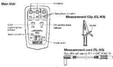
[3] NAMES OF PARTS
![Sanwa KS3 - [2] APPLICATION AND FEATURES - 2](/content/2026/05/956487/images/97291801a19a545a1013a427ee6ee51028272fb6af67b73d76e402a7f8fdbec3.jpg)
[4] DESCRIPTION OF FUNCTIONS
4-1 Power switch
Switches the power on and off. After measurement, be sure to set this switch to OFF to prevent wasteful battery consumption.
Note. This instrument does not have the auto power-off
4-2 Open phase indicators
In the three-phase power line check, each indicator lights up when the corresponding line is live. An extinguished indicator means that the phase of the line is open.
Note: Each LED indicator lights at an input of about 30 V or more. These indicators do not light during the motor rotation check because the input voltages are less than 30 V.
4-3 Input jacks
Insert the measurement cords into the jacks of the same colors.
4-4 CW indicator (Clockwise = positive phase)
Lights (in green) when the phase is positive.
4-5 CCW Indicator (Counterclockwise = negative phase)
Lights (in red) when the phase is negative. 4-8 Power ON indicator (Low battery warning)
- Power on indicator (Low, Butler) Warning. Lights when the power is on
It stops lighting when voltage of the built-in battery drops to 6.0 V or lose. Replace the battery with a new one as soon as possible if the indicator will not light.
[5] MEASUREMENT PROCEDURES
WARNING
- Do not perform measurement of a voltage exceeding the maximum rated voltage.
- During measurement, do not hold the measurement clip at any point beyond the barrier.
5-1 Pre-operational Check
Perform pre-operational check for safety.
- Check the external appearance. Check that there is no abnormality with the main unit and measurement clips. Check that there is no abnormality with the cord such as disconnection or cracking.
- Check the lighting of the open phase indicators and the functioning of the phase detection by clipping cables with known voltages and phases. If one or more indicator(s) do not light, the measurement cord(s) may be disconnected or the built-in fuse may be blown.
Note: For the fuse replacement, please contact us (see section 7-2).
- If the Power ON indicator will not light, replace the battery with a new one.
5-2 Checking the three-phase power lines
CAUTION
-
The open phase indicators do not light if any of the line voltages is less than 30 V.
-
The CW or CCW indicator lights up even when there is an open phase, but the operation is not guaranteed. Be above sure to check the phase
but this operation is not guaranteed. Do always sure to check the phase sequence while all of the open phase indicators are ON.
- This instrument cannot be used with three single-phase lines.
(1) Insert the three measurement cords into the input jacks.
(2) Set the Power switch to ON.
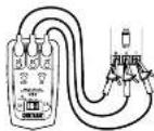
(3) Connect the three measurement clips to R-S-T of the three-phase AC power supply as shown below (correct measurement is impossible if only two of them are connected).
Connect the red measurement clip to R, the white measurement clip to S and the blue measurement clip to T
Note: Illustrations of ON/OFF status of the indicators in this manual
LED ON indication LED OFF indication
(4) Check the open phase.

In the example above, the indicators of the R- and S-phases are ON and the indicator of the T-phase is OFF, which means that the phase of T is an open phase. * The CW or CCW indicator lights up even when there is an open phase, but the operation is not guaranteed. Be always sure to check the phase sequence while all of the open phase indicators are ON

(5) Check whether the phase is positive or
negative.
When the phase is positive (clockwise).
the CW indicator lights green. When the
please be negative (enumber the CCWindsor irits and

The example above shows the status
in which the phase of R, S and T is positive
5-3 Checking the motor rotation direction
A CAUTION
- Before measurement, make sure that no voltage is applied to the motor.
- If an open phase is detected in the motor rotation direction check, turning the motor shaft in either direction lights either or none at the CW and
CCW indicators. Be sure to check by turning it in both directions. - Correct judgment is impossible if the turning speed is low. Be sure to
check by turning the motor shaft at a certain speed (the specified rotation speed cannot be reached if it is half stopped or turned at a low speed).
(1) Insert the three measurement cords into the input jacks.
Set the Power switch to ON.
(3) Connect the three measurement clips to L1-L2-L3 of the motor as show below (correct measurement is impossible if only two of them are connected).
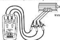
(4) Turn the motor shell at a speed higher than the specified rotation speed.
When the phase is positive (clockwise), the CW indicator lights green. When
the phase is negative (counterclockwise), the CCW indicator lights red.
The specified solution spots refers to 2 relations of more per sols. This figure is variable depending on the number of motor poles.
* If there is an open phase, turning the motor shell in silk
either or none of the CW and CCW indicators. Be sure to check by turning it
in both directions.
* Certain motors may rotate in the opposite direction when they are connected in
[6] MAINTENANCE
WARNING
The section is very important for safety. Head and understand the following instructions fully and maintain your instrument properly.
6-1 Maintenance and Inspection
Before use, check the instrument as specified (see section 5-1) to confirm that there is no abnormally. If anything is abnormal, do not use the instrument and return it to your authorized Sanwa agent or distributor for repair.
5-2 Repair
For details, please contact your authorized Sanwa agent or distributor.
6-3 Storage
CAUTION
- The panel and case are not resistant to volatile solvent and must not be cleaned with thinner or alcohol.
- The panel and case are not resistant to heat. Do not place the instrument
near heat-generating devices (such as a soldering iron). - Do not store the instrument anywhere it may be subject to vibrations or could fall.
- What is going the visitor here, what is, that of his and his father, visitors is exposed to direct sunlight, or locations where compensation is anticipated.
- When the instrument is not going to be used for an extended time, be sure to remove the batteries.
6-4 Battery Replacement
● The battery loaded at the factory is a monitor battery, so their service life may be shorter than that of a brand-new battery. A monitor battery is a type of battery used to check the functions and performance of a product.
WARNING
To avoid electric shock when replacing the ballenes, first disconnect the measurement clips from the object to be measured, and turn off the power.
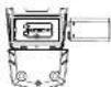
① Remove the fixing screw (x 1) from the battery compartment cover. ② Slide the battery compartment cover downward to remove it. ③ Replace the battery with new ones. ④ Plac the battery compartment cover and tighten the fixing screw.
[7] AFTER-SALE SERVICE
-1 Warranty and Provision
Sanwa offers comprehensive warranty services to its end-users and to its product resellers. Under Sanwa's general warranty policy, each instrument is warranted to be free from defects in workmanship or material under normal use for the period of one (1) year from the date of purchase.
This warranty policy is valid within the country of purchase only, and applied only to the product purchased from Sarwa authorized agent or distributor. Sarwa reserves the right to inspect all warranty claims to determine the extent to which the warranty policy shall apply.
This warranty shall not apply to the battery, measurement cable and measurement clips provided with the product, which have been subject to one of the following causes:
1. A failure due to improper handling or use that deviates from the instruction manual.
2. A failure due to inadequate repair or modification by people other than Sarwa andla personnel.
3. A failure due to causes not attributable to this product such as fire, flood and other natural disaster.
-
Non-operation due to a discharged battery
-
A failure or damage due to transportation, relocation or dropping after the purchase.
7-2 Repair
Customers are asked to provide the following information when requesting services:
-
Customer name, address, and contact information
-
Description of problem
-
Description of product configuration
-
Model Number
-
Product Serial Number
-
Proof of Date-of-Purchase
-
Where you purchased the product Please contact Sanwa authorized agent / distributor / service provider, listed in
our website, in your country with above information. An instrument sent to Sanwa
/agent / distributor without those information will be returned to the customer. Note
1) Prior to requesting repair, please check the following:
- Capacity and installation polarity of the built-in batteries
• Continuity of the test leads.
2) Repair during the warranty period:
The failed instrument will be repaired in accordance with the conditions anticipated in '7-1 Warranty and Provision'.
Situated in 1-1 Walling and Provision. Stillear after the warranty period has expired:
In some cases, repair and transportation cost may become higher than the
price of the product. Please contact Samba authorized agent / service provider in advance. The minimum retention period of service functional parts is 6 years after the discontinuation of manufacture. This retention period is the repair warranty period. Please note, however, if such functional parts become unavailable for reasons of discontinuation of manufacture, please return to the manufacturer's website.
etc., the retention period may become shorter accordingly. (1) Procaulions when sending the product to be repaired.
To ensure the safety of the product during transportation, place the product in a box that is larger than the product 5 times or more in volume and fill cushion materials fully and then clearly mark "Repair Product Enclosed" on the box surface. The cost of sending and returning the product shall be borne by the customer.
7-3 SANWA Website
http://www.sanva-meter.co.jp
E-mail: exp sales@sanwa-meter.co.jp
[8] SPECIFICATIONS
| Operating voltage range | Three-phase line voltage 75 to 80 V AC (same wave continuous). |
| Download projection input | 63A x 2.9 |
| Frac testing | 4.5 x 20 mm, 0.5 A/60 V. Breaking capacity 50 kJ. |
| Power frequency range | 40 to 460 Hz. |
| Motor rotation direction | Dose maximum at rotation speed from 2 Hz (2 rotational speeds) to 300 Hz. |
| Operation environment | Altitude 2009 or less, lower up, environmental pollution degree 1. |
| Operating temperature/ humidity range | 0 to 40 °C, 80 % Hr or less (without convection). |
| Storage temperature/ humidity range | -10 to 40 °C, 90 % RH or light without convection. |
| Power supply | Akoule 9 V battery ELISA (VCL 12, 1904 A) x-1 |
| Power consumption | Apouse, 5 mA stangle daily, approx. 16 mA (AVAX) |
| Low battery indication | Power ON indicator steps lighting at alarm: 6.8 V at bus. |
| Continuous operation duration | Apouse, 60 hours |
| Dimensions and sizes | 120 x 142 x 72 x 30 (20 mm, approx. 210 g including battery). |
| Safety standards | IEC0101C-1, CAT, 81 B 500 V, IEC01557-17, IEC0101C-2, 0.056, IEC0101C-081. |
| EWC electrode, Roll-off receive | IEC01839-1 (EWC), ENX0081 (REHS). |
| Accessories | Measurement clips (CL-KS), measurement cords (LTD), measurement mode, carrying push (CK-SK). |
![Sanwa KS3 - [7] AFTER-SALE SERVICE - 1](/content/2026/05/956487/images/4178ac97e5c0b710d485e6b280b1904e5b444e3f15047d2e96be1dbe6811ea66.jpg)
Brand : Sanwa
Model : KS3
Category : Detector