PC710 - Multimeter Sanwa - Free user manual and instructions
Find the device manual for free PC710 Sanwa in PDF.


| Type | Digital Multimeter |
| Model | PC710 |
| Display | LCD main display 9999/6000/2000 counts, sub display 9999/6000 counts, 41-segment analog bar graph |
| Measurement Functions | AC/DC voltage, AC/DC current, resistance, capacitance, frequency, duty cycle, temperature, continuity, diode test, conductance, EF detection |
| True RMS | Yes (AC coupling) |
| Max. Voltage Range | 1000 V DC/AC (CAT II), 600 V AC/DC (CAT III) |
| Dimensions (without holster) | Approx. 175 mm × 80 mm × 40 mm |
| Dimensions (with holster) | Approx. 184 mm × 86 mm × 52 mm |
| Weight (without holster) | Approx. 360 g |
| Weight (with holster) | Approx. 430 g |
| Power Source | 9V battery (6LR61, 6LF22, NEDA1604A) |
| Battery Life | Approx. 60 hours (DCV measurement) |
| Auto Power Saving | After approx. 30 minutes of inactivity |
| Safety Compliance | IEC61010-1, CAT III 600V, CAT II 1000V, double insulation |
| Accessories Included | Test leads (TL-23a), holster (H-700) with light shielding magnet cap, K-type thermocouple (K-250PC), instruction manual |
| Fuse Protection | 0.4A/1000V (F1211) and 11A/1000V (F1412) fuses |
| PC Interface | Optical isolated port, compatible with optional USB optical unit (KB-USB7) and software PCLink7 |
| Operating Temperature | 5 °C to 40 °C (80% RH max.) |
| Storage Temperature | -10 °C to 50 °C (80% RH max., battery removed) |
| Warranty | 1 year from date of purchase (within country of purchase) |
Frequently Asked Questions - PC710 Sanwa
User questions about PC710 Sanwa
0 question about this device. Answer the ones you know or ask your own.
Ask a new question about this device
Download the instructions for your Multimeter in PDF format for free! Find your manual PC710 - Sanwa and take your electronic device back in hand. On this page are published all the documents necessary for the use of your device. PC710 by Sanwa.
USER MANUAL PC710 Sanwa
[1] SAFETY PRECAUTIONS
1-1 Explanation of Warning Symbols 1
1-2 Warning Instructions for Safe Use 2
1-3 Overload Protection 3
[2] APPLICATIONS AND FEATURES
2-1 Applications 4
2-2 Features 4
[3] Parts Identification
3-1 Multimeter and Test Leads 5
3-2 Display 7
[4] DESCRIPTION OF FUNCTIONS
4-1 Power Switch/Function Selector 8
4-2 Auto Power Saving 8
4-3 Low Battery Indication 9
4-4 Measuring Function Selection 9
4-5 Electric Field Detection 10
4-6 Range Hold 11
4-7 DH Data Hold 11
4-8 Beeper Control 11
4-9 PC (Personal Computer) Interface 12
4-10 Test Leads Improper Connection Warning 13
4-11 CAPTURE Crest capture mode (Sampling time: 1 ms).... 13
4-12 REC MAX/MIN/AVG Recording Mode 13
4-13 △ Relative Measurement 14
4-14 Back Light 14
4-15 Terms 14
4-16 Messages on the display 15
[5] Measuring procedures
5-1 Pre-operational Check 16
5-2 AC Voltage ( ∅ ) / Frequency (Hz) Measurement ...... 18
5-3 DC/AC Voltage (V) Measurement 21
5-4 DC/AC Voltage (mV), Logic-Level Frequency ( Hz) and Duty Cycle ( D%) Measurement 23
5-5 AC Voltage (m ) / Frequency (Hz) Measurement 26
5-6 Resistance (Ω) Measurement, Continuity Check ( ), and Conductance (nS) Measurement 28
5-7 Temperature Measurement 31
5-8 Capacitance ( -H) Measurement, Diode (→Fest 33 5-9 DC/AC Current (A), AC Current (m A μA μA)/ Frequency (Hz) Measurement 37
5-10 Measurements with Separately Available Accessories 43
[6] MAINTENANCE
6-1 Simple Examination 47
6-2 Calibration 48
6-3 Battery and Fuse Replacement 48
6-4 Storage 49
[7] AFTER-SALE SERVICE
7-1 Warranty and Provision 50
7-2 Repair 50
8-1 General Specifications 52
8-2 Measuring Range and Accuracy 54
[1] SAFETY PRECAUTIONS
\*Before use, read the following safety precautions.
This instruction manual explains how to use your digital multimeter PC710. Before using, read through this manual to reduce the risk of fire, electric shock, and/or injury. And save it together with the product so that you can refer to the manual as necessary.
Use the instrument only as specified in this manual or the protection provided by the instrument may be impaired.
The instructions given under the headings of " △ WARNING" and must be followed to prevent accidental burn and electric shock.
1-1 Explanation of Warning Symbols
The meanings of the symbols used in this manual and attached to the product are as follows.
▲:Extremely-important instructions for safe use
- WARNING identifies conditions and actions that could result in accidental burn and electric shock.
- CAUTION identifies conditions and actions that could cause damage the instrument.
⚠️: Do not touch! Possible high voltage.
÷:Ground :Diode ➕z:Frequency
☐:Fuse :Beep •)) NHz:Logic-Level Frequency
: Direct Current(DC)-H:Capacitor :Duty Cycle
\~ :Alternate Current (AC) : Nano-Siemens (Conductance)
Ω:Resistance Temp:Temperature :Backlight
EF:Electric Field ☐ : Double Insulation or Reinforced
1-2 Warning Instructions for Safe Use
WARNING
-
Do not use the instrument if the meter or test leads look damaged.
-
Be sure to use the specified fuse. Neither use unspecified fuse nor short-circuit the fuse holder.
-
Do not apply higher voltage or current than the max. ratings by each function. (See 1-3)
-
Use caution when working with voltages above 33V ac rms, 46.7 V ac peak, or 70V dc. These voltages pose a shock hazard.
-
Do not use the meter to measure lines that may have inductive voltage or surge voltage (e.g. motors) because the input voltage may exceed the maximum rated voltage.
-
Never operate the meter with the case or battery lid removed.
-
Remove test leads from the meter before opening the meter case for replacing the battery or fuse.
-
Never attempt to repair or modify the instrument, except for battery and fuse replacement.
-
Do not use any unspecified type of test leads.
-
Keep your fingers behind the finger guards of the test leads while measurement.
-
Connect the common test lead (Black) before you connect the live test lead (Red). Disconnect the live test lead first.
-
Make sure the function, range, and measuring terminals are properly set.
-
Do not switch the function, range, or the plugs to another while measurement.
-
Do not operate the meter when it is wet or with wet hands.
CAUTION
Incorrect measurement may be performed in a ferromagnetic or intense electric field near transformers, high-current circuits, and radio equipments.
1-3 Overload Protection
| Function | Measuring Terminal | Max. Rated Input | Overload Protection |
| Hz, |  and COM and COM | 1000 V dc/ac | 1100 Vrms |
| _Hz^ * mV | 10 V dc/ac | ||
| _ 0mV , -H | Do not apply any voltage or current. | ||
| 「Temp」 | 50 mV dc | ||
| A _Hz _Hz | mAμA and COM | 600 mA dc/ac Do not apply any voltage. | 0.4 A/1000 V Fuse*Breaking capacity: 30 kA |
| _Hz | A and COM | 10 A dc/ac Do not apply any voltage. | 11 A/1000 V FuseBreaking capacity: 20 kA |
*The 0.4A fuse has a Time-Current Characteristic Curves projection of approaching infinity at 0.6 A.
It has a fast acting characteristic of below 0.1 second at beyond 1.5 A. This protection characteristic matches this meter nicely.
[2] APPLICATIONS AND FEATURES
2-1 Applications
This instrument is a portable digital multimeter designed to measure light electric circuits. The instrument offers not only measurements for small communication equipments, home electric appliances, output from a wall socket, and many batteries, also circuit analyses with additional functions.
2-2 Features
- Compliant with IEC61010-1 CATIII 600 V, CAT. II 1000 V, and safe design using fuses with large number of breaking capacity.
• 9999 count display (ACV, DCV, Hz, nS) - Fast response display
(Numeric parts: 5 times/Sec. Bar graph part: 60 times/Sec.) - Dual Display shows "Voltage or Current and its Frequency", and "AC components and DC components of Voltage or Current"
• True RMS detection for alternate current (AC) (True RMS)
• Maximum DC/AC voltage measurement resolution: 0.01 mV
• Frequency (Sensitivity selectable), - Dual Display shows "Voltage or Current and its Frequency", and "AC components and DC components of Voltage or Current"
- True RMS detection for alternate current (AC) (True RMS)
- Maximum DC/AC voltage measurement resolution: 0.01 mV
- Frequency (Sensitivity selectable),
Wide capacitance range (0.01 nF to 25.00 mF)
• EF(Electric Field) Detection to indicate signal strength of electric field which surrounds current-carrying conductors.
• Automatically range selectable Crest Capture Mode Sampling time: Approx. 1 ms
• MAX/MIN/AVG recording mode with auto ranging (Sampling rate: 20 times/Sec.)
• Relative mode with auto ranging
• Back light to allow for easy visibility in low-lit area
• Temperature measurement
(K-type thermocouple: -50 °C to 1000 °C ) - PCLink7 (separately available software) allows you to download logged data into your PC with USB optical communication unit (KB-USB7)
[3] Parts Identification
3-1 Multimeter and Test Leads
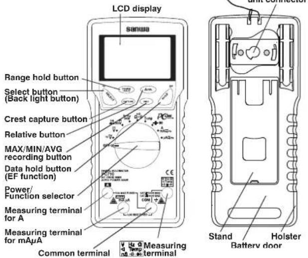
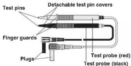
Test leads TL-23a
With the detachable test pin covers: CAT. III 600 V
Without the detachable test pin covers: CAT. II 1000 V
How to detach the light shielding magnet cap
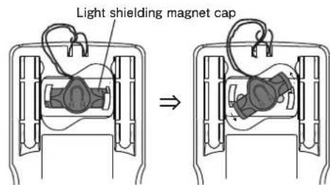
Turn the light shielding magnet cap counterclockwise to detach.
An application of the light shielding magnet cap
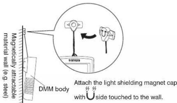
Note:
Keep the light shielding magnet cap away from cellular phones, analog watches, floppy disks, magnetic cards, magnetic tapes, and magnetic tickets. Otherwise, the memorized information may be lost.
3-2 Display
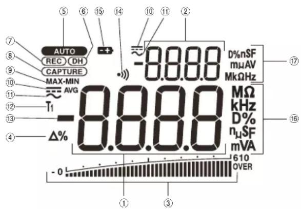
| 1 | Main display |
| 2 | Sub display |
| 3 | Analog bar graph |
| 4 | Relative mode indicator |
| 5 | Auto range mode indicator |
| 6 | Data hold indicator |
| 7 | Recording mode indicator |
| 8 | Crest capture mode indicator |
| 9 | Max/Min/Avg updating indicator |
| 10 | DC measurement indicator |
| 11 | AC measurement indicator |
| 12 | Temperature measurement indicator |
| 13 | Polar character |
| 14 | Continuity check indicator |
| 15 | Low battery voltage indicator |
| 16 | Unit of readings for main display |
| 17 | Unit of readings for sub display |
[4] DESCRIPTION OF FUNCTIONS
4-1 Power Switch/Function Selector
Turn the switch to turn on/off the power and select a measuring function. All segments of the LCD display will be turned on for 1 seconds after power-on, and then the meter will be ready to use.
Note:
The push buttons between the display and the function selector work differently depending on how long you press. In this manual, "press" means pressing momentary and "press and hold for 1 sec. or more" means pressing longer.
4-2 Auto Power Saving
The Auto Power Saving mode turns the meter off automatically after approximately 30 minutes of no activities. While the Auto Power Saving mode, following activities set the auto power saving back.
1) Function selector or push button operations
2) Non-OL readings in the function, diode test, or continuity check, non-zero readings in the Duty cycle/Frequency measurement functions, any readings in the temperature measurement function, or significant measuring readings of above 512 counts in the other function ranges
Following activities disable the Auto Power Saving mode automatically.
1) Crest capture mode or MAX/MIN/AVG recording mode is in use
2) Data communication to your PC is in use
4-2-1 How to get back from the Auto Power Saving
Press the SELECT, RANGE HOLD, △ REL, or HOLD button, or disconnect the object to measure and turn the power switch off and then back on, and select a function before connecting the object.
4-2-2 How to disable the Auto Power Saving
Press the SELECT button while turning the meter power on. Release the SELECT button after AUTO is turned off. (All segments of the display turn on after power-on.) Then the meter will be ready to use.
Turn the power switch OFF and then back on to resume.
Note:
Even in the Auto Power Saving mode, approx. 50 A will be consumed. When in the auto power saving mode, intense light like the direct sunlight into the optical communication unit on the back of the DMM increases the consumption current. Mount the attached light shielding magnet cap on the optical comminucation unit connector when not in use. Always turn the power switch to the OFF position when the meter is not in use for a long time.
4-3 Low Battery Indication
Decreasing the internal battery voltage to approx. 7 V due to wearing down turns on the + indicator on the LCD display. Replace the battery with new one when the indicator turns on.
Use under "Low Battery" may cause malfunctions and "InEr" may be indicated on the display. Replace the battery with new one to release the error.
4-4 Measuring Function Selection
At each position of the function selector, press SELECT button ( ) to select measuring functions as follows.
* Dual display: [Main display/Sub display]
· [ Hz ] : [ / Hz] [Hz / ]
· 「 」:[ ] [
· [ D % Hz m ]: [m ] [m m ] [ Hz [D %] [m
· :[m/Hz][Hz/m..
· ^nS : [] []) [nS] []
- Temp : [C] F
·「-|+▶」:[+] ⇔ [▶]
$$ \begin{array}{l} \cdot \left[ \begin{array}{l} \mathbf {A} \ m \mathbf {A} \overline {{\overline {{\mathbf {A}}}}} _ {\mathrm{Hz}} \end{array} \right]: [ (m) \overline {{\overline {{\mathbf {A}}}}} ] \Rightarrow [ (m) \overline {{\overline {{\mathbf {A}}}}} ^ {\prime} (m) \widetilde {\mathbf {A}} ] \Rightarrow [ (m) \widetilde {\mathbf {A}} ^ {\prime} \mathrm{Hz} ] \Rightarrow [ (m) \overline {{\overline {{\mathbf {A}}}}} ] \Rightarrow \dots \ \cdot \left[ \mu \mathbf {A} \text { 玉Hz } \right]: [ \mu \overline {{\mathbf {A}}} ] \Rightarrow [ \mu \overline {{\mathbf {A}}} / \mu \widetilde {\mathbf {A}} ] \Rightarrow [ \mu \widetilde {\mathbf {A}} / \mathrm{Hz} ] \Rightarrow [ \mu \overline {{\mathbf {A}}} ] \Rightarrow \dots \ \end{array} $$
Note:
The last selection of each function will be saved as power up default for repeat measurement convenience.
4-5 EF (Electric Field) Detection
At any function, press the EF button for one second or more to toggle to EF-Detection feature. The meter displays "E.F." when it is ready. Signal strength is indicated as "----" on the numeric part of the display plus variable period of intermittent beep tones.
- Non-Contact EF-Detection: An antenna is located along the top of the meter, which detects electric field surrounds current-carrying conductors. It is ideal for tracing live wiring connections, locating wiring breakage and to distinguish between live or earth connections.
- Probe-Contact EF-Detection: To perform more precise detection of live wires, apply the red (+) test probe to the live wire for direct contact measurement.
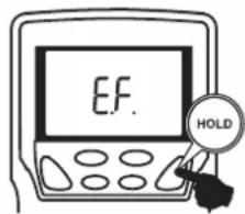
More than 1 second
Ungrounded (live) conductor
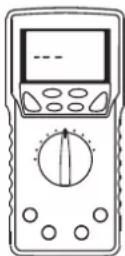
•
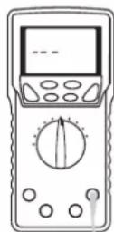
Ungrounded (live) conductor

Non-Contact EF Probe-Contact EF
4-6 Range Hold
Press the RANGE HOLD button to select manual-ranging, and the meter will remain in the range it was in. (AUTO turns off.) In the manual-ranging mode, press the button again to step through the ranges. Select an appropriate range making sure units and decimal point positions. To resume auto-ranging mode, press and hold the button for 1 second or more.
Note:
Manual ranging mode is not available in the Hz functions.
4-7 DH Data Hold
Press HOLD button to freeze present reading for later view. (DH indicator turns on.) Input fluctuation will not reflect on the indicated value. Press the HOLD button again to disable the data hold feature and go back to the normal measurement mode. (DH indicator turns off.)
Note:
Function changes or functional operations will cancel the data hold feature.
4-8 Beeper Control
Press the RANGE HOLD button while turning the meter power on to disable the beeper. Release the RANGE HOLD button after •) is turned off. (All segments of the display turn on right after power-on.) Then the meter will be ready to use. Turn the power switch OFF and then back on to resume.
Note:
The beeper for the continuity check and the plug improper connection warning will not be disabled.
4-9 PC (Personal Computer) Interface
The instrument equips with an optical isolated interface port at the meter back for data communication. KB-USB7, dedicated USB optical communication unit (separately available), and PCLink7, dedicated software, allow you to transfer real time readings and internally logged data to your PC. For more information, see the "HELP" for PCLink7 (PC linkage software).
USB Optical Communication Unit
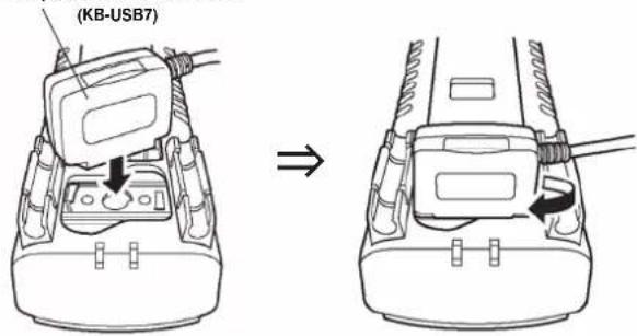
Optical Communication Unit Connection
Note:
Intense light like the direct sunlight into the optical communication unit on the back of the DMM increases the consumption current. Mount the attached light shielding magnet cap on the optical comminucation unit connector when not in use.
4-10 Test Leads Improper Connection Warning
The meter beeps as well as displays "InEr" to warn the user against possible damage to the meter due to test leads improper connections to the mAμA, or A measuring terminals when other function (like voltage function) is selected. (Temperature measurement function is an exception.)
Note:
"InEr" warning may be indicated due to weak battery even if the test leads are connected properly.
4-11 CAPTURE Crest capture mode (Sampling time: 1 ms)
Press the CAPTURE button to activate the crest (Instantaneous Peak-Hold) mode to capture voltage or current signal duration which is longer than 1 ms. CAPTURE and MAX indicators turn on. The meter beeps when new MAX (maximum) or MIN (minimum) reading is updated. Press the button to read the MAX, MIN, and MAX-MIN (peak to peak) readings in sequence. Press the button for 1 sec. or more to exit the crest mode. Auto-ranging (up range) remains, and Auto Power Saving is disabled automatically in this mode.
4-12 REC MAX/MIN/AVG Recording Mode
When this mode is activated, the reading update rate will be increased to 20 times/sec. in the voltage measurement or current measurement function, and the update rate in the other function ranges will remain.
Press the REC button to activate the MAX/MIN/AVG recording mode. REC, MAX, MIN, and AVG turn on. The meter beeps when new MAX (maximum) or MIN (minimum) reading is updated. Press the button to read the MAX, MIN, MAX-MIN (peak to peak) and AVG readings in sequence. Press the button for 1 sec. or more to exit the MAX/MIN/AVG recording mode. Auto-ranging remains, and Auto Power Saving is disabled automatically in this mode.
4-13 △ Relative Measurement
Press the △REL button to activate the relative measurement mode and △ indicator turns on. The relative measurement mode offsets the meter to display relative values against a reference. The meter displays its readings subtracting the reading at the moment the △ REL button is pressed. Press △ REL button again to exit the relative measurement mode. This feature is available also while the MAX/MIN/AVG recording mode. This function works only on the main display.
4-14 Back Light
Press the SELECT button for 1 sec. or more to turn the backlight on. (Automatically turns off after approx. 30 sec.) Press the SELECT button again for 1 sec. or more to turn the backlight off.
4-15 Terms
Analog bar graph
The analog bar graph provides a visual indication of measurement like a traditional analog meter needle.
True RMS
True RMS is a term which identifies a DMM that responds accurately to the effective RMS value regardless of the waveforms such as: square, sawtooth, triangle, pulse trains, spikes, as well as distorted waveforms with the presence of harmonics. This instrument employs the True-RMS (Root-Mean-Square) detection.
Crest Factor
Crest Factor is the ratio of the Crest (instantaneous peak) value divided by the True RMS value. Most common waveforms such as sinusoidal wave and chopping wave have a relatively low crest factor. A low duty cycle wave form like pulse string has a high crest factor. For voltages and crest factors for typical waveforms, see the following table. Please note that measurement should be made under the crest factor below 3.
| Input Waveform | 0 to PEAK Vp | RocI Mean Square Value Vrms | Average Value Vavg | Crest Factor Vp/Vrms | Form Factor Vrms/Vavg | |
| Sinusoidal wave | |c:c Vp & 2 \ 0 & p | Vp | 2 =0.707Vp | 2Vp =0.637Vp | 2 =1.414 | 22 =1.111 |
| Square wave | |c:c Vp & 2 \ 0 & | Vp | Vp Vp | 1 | 1 | |
| Chopping wave | |c:c Vp & 2 \ 0 & | Vp | 3 =0.577Vp | 2 =0.5Vp | 3 =1.732 | 23 =1.155 |
| Pulse | |c:c Vp & 2 \ 0 & | Vp | 2 · Vp | 2 · Vp | 2 | 2 |
Waveforms and Voltages
4-16 Messages on the display
| Messages | Description | What to do |
| InEr | Test leads improper connection warning (Malfunction when low battery) | See 4-10 (Page 13) See 4-3 (Page 9) |
| rE-O | Self-diagnostic | See 6-2 (Page 47) |
| C_Er |
[5] Measuring procedures
5-1 Pre-operational Check
WARNING
- Do not use the instrument if the meter or test leads look damaged.
- Make sure the test leads and the fuse are not broken.
CAUTION
Make sure the low battery indicator is off after power-on. Replace the battery with new one if the indicator is on.
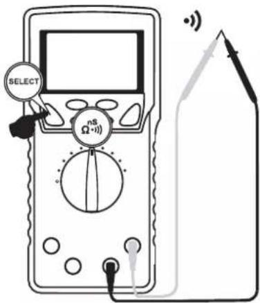
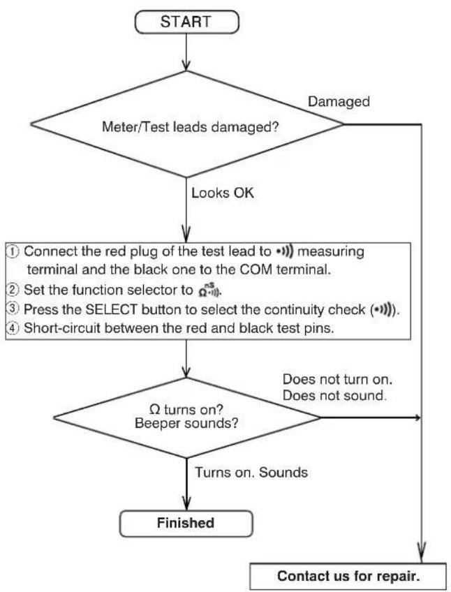
Perform pre-operational check for safety.
(Inspection using continuity check)
flowchart
graph TD
    A["START"] --> B{Meter/Test leads damaged?}
    B -->|Damaged| C["Looks OK"]
    B -->|Damaged| D["Does not turn on. Does not sound."]
    C --> E{Ω turns on? Beeper sounds?}
    E -->|Turns on. Sounds| F["Finished"]
    E -->|Does not turn on. Does not sound.| G["Contact us for repair."]
    E --> H["Connect the red plug of the test lead to •••) measuring terminal and the black one to the COM terminal.<br>Set the function selector to Ω••••.<br>Press the SELECT button to select the continuity check (••••).<br>Short-circuit between the red and black test pins."]
*In the case nothing is displayed, check for the battery.
5-2 Hz (Max. rated input voltage: 1,000 V dc/ac)
• AC Voltage )/Frequency (Hz) Simultaneous Measurement
WARNING
- Do not apply any input signal exceeding the max. rated input voltage.
- Do not switch the function selector while measuring.
- Keep your fingers behind the finger guards of the test leads while measurement.
1) What to measure
- (ACV): Sine wave voltages such as output from a wall socket.
· Hz (Frequency): Frequency on a AC circuit.
2) Measuring ranges
· : 9.999 V, 99.99 V, and 999.9 V
• Hz: 15.00 Hz to 10.00 kHz (Auto ranging)
3) Measuring procedure
① Connect the red plug of the test lead to the VHz measuring terminal and the black one to the COM terminal.
② Set the function selector to HzV.
③ Press the SELECT button to select a display style.
④ Apply the test pins (Red and Black) to the object to measure.
⑤ Read the display.
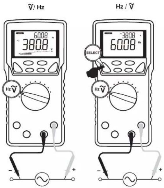
Note:
Hz input sensitivity varies automatically with a selected voltage range. 9.999 V range has the highest sensitivity and the 999.9 V range has the lowest. Auto ranging measurements normally set the most appropriate trigger level. You can also press the RANGE HOLD button to select another trigger level (voltage range) manually.
If the Hz reading becomes unstable, select higher voltage range to avoid electrical noise. If the reading shows zero, select lower voltage range.
| Range | Frequency measurement (Hz)Input sensitivity (Sine wave) | Frequency range |
| 9.999 V 2.5 V | 15.00 Hz ~ 10.00 kHz | |
| 99.99 V 25 V | ||
| 999.9 V 100 V | ||
The display style of [Hz/] does not show the bar graph.
As a normal condition, non-connected test leads may cause unstable readings.
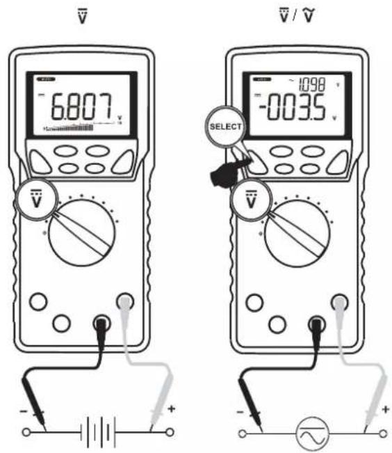
5-3 [V] (Max. rated input voltage: 1,000 V dc/ac)
• DC Voltage( ) measurement
- DC Voltage( )/AC Voltage( ) simultaneous measurement
WARNING
- Do not apply any input signal exceeding the max. rated input voltage.
- Do not switch the function selector while measuring.
- Keep your fingers behind the finger guards of the test leads while measurement.
1) What to measure
· (DC Voltage): Batteries, DC circuit voltages, etc.
· / voltage component/AC voltage component)
2) Measuring ranges
· , 9.999 V, 99.99 V, 999.9 V
3) Measuring procedure
① Connect the red plug of the test lead to the V measuring terminal and the black one to the COM terminal.
② Set the function selector to
③ Press the SELECT button to select a function you want to perform.
④ Apply the test pins (Red and Black) to the object to measure.
⑤ Read the display.
Note:
- The display style of V / V does not show the bar graph.
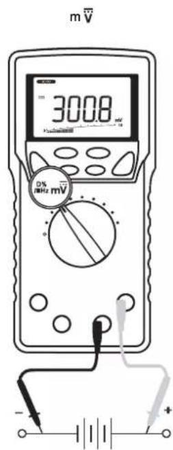
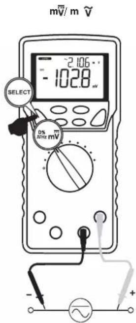
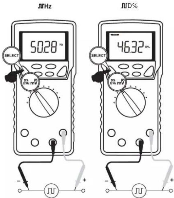
5-4 % Hz (Max. rated input voltage: 10 V dc/ac)
• DC voltage (m ) measurement
- DC Voltage (mV)/AC Voltage(mV) simultaneous measurement
- Logic-level frequency ( MHz ) measurement
• Duty cycle ( D% ) Measurement
WARNING
- Do not apply any input signal exceeding the max. rated input voltage.
- Do not switch the function selector while measuring.
- Keep your fingers behind the finger guards of the test leads while measurement.
1) What to measure
· m (DC voltage): DC circuit voltage lower than 600 mV
· m /m voltage component/AC voltage component)
- MHz (Logic level frequency): 3 V, 5 V logic circuit frequency
- % (Duty cycle): Logic level signal duty cycle (Square wave)
2) Measuring ranges
· m , m : 60.00 mV and 600.0 mV
• MHz: Auto ranging, 5.000 Hz to 1.000 MHz (Square wave)
- JJD% : 0.00% to 100.0% (Square wave 5 Hz to 10 kHz)
3) Measuring procedure
① Connect the red plug of the test lead to the VHz measuring terminal and the black one to the COM terminal.
② Set the function selector to %MHz ± mV .
③ Press the SELECT button to select a function you want to perform.
④ Apply the test pins (Red and Black) to the object to measure.
⑤ Read the display.
Note:
The display style of [m /m [ ], H, D%] does not show the bar graph.
5-5

(Max. rated input voltage: 600 mV dc/ac)
- AC Voltage (mV)/Frequency (Hz) Simultaneous Measurement
WARNING
- Do not apply any input signal exceeding the max. rated input voltage.
- Do not switch the function selector while measuring.
- Keep your fingers behind the finger guards of the test leads while measurement.
1) What to measure
· m (AC voltage): AC voltage lower than 600 mV
- Hz(Frequency): Frequency on a AC circuit lower than 600 mV
2) Measuring ranges
· m : 60.00 mV and 600.0 mV
· Hz: 15.00 Hz to 10.00 kHz (Auto ranging)
3) Measuring procedure
① Connect the red plug of the test lead to the VHz measuring terminal and the black one to the COM terminal.
② Set the function selector to .
③ Press the SELECT button to select a function you want to perform.
④ Apply the test pins (Red and Black) to the object to measure.
⑤ Read the display.
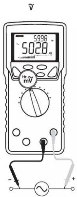
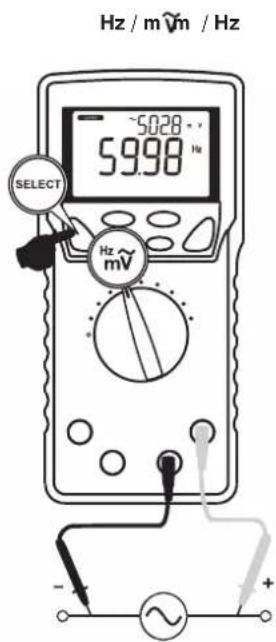
Note:
| Range | Frequency measurement (Hz)Input sensitivity (Sine wave) | Frequency range |
| 60.00 mV 40 | mV | 15.00 Hz ~ 50.00 kHz |
| 600.0 mV 60 | mV |
• The display style of [Hz/m] does not show the bar graph.
- As a normal condition, non-connected test leads may cause unstable readings.
5-6 ^nS (Do not apply any voltage or current.)
• Resistance (Ω) measurement
• Conductance (nS) Measurement
• Continuity Check (•))
WARNING
Do not apply any voltage or current to the measuring terminals.
CAUTION
In the case of high resistance measurement, readings may be unstable due to external inductive influence.
1) What to measure
- (Resistance): Resistor, circuit resistance, etc.
• •••(Continuity check): Wiring connections, Operation of switches, etc. - nS(Conductance): High-value resistance of Giga-Ohms for leakage measurements
Note: Conductance is the inverse of Resistance, that is S=1/Ω or nS=1/GΩ.
2) Measuring ranges
· Ω: 6 ranges; 600.0 Ω, 6.000 kΩ, 60.00 kΩ, 600.0 kΩ, 6.000 MΩ, and 60.00 MΩ
• • ) ) : Beeper threshold level: between 20 Ω and 300 Ω, Response time: <100 μs
· nS : 99.99 nS (Single range)
*Open circuit voltage between the measuring terminals: <1.2 V dc (<1.0 V dc for 60.00 MΩ range)
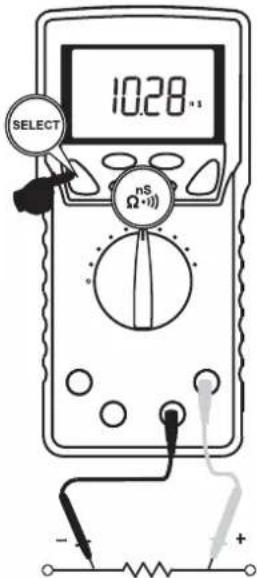
3) Measuring procedure
① Connect the red plug of the test lead to ^ns measuring terminal and the black one to the COM terminal.
② Set the function selector to ^nS
③ Press the SELECT button to select a function you want to perform.
④ Apply the test pins (Red and Black) to the object to measure.
⑤ Read the display.
(•)) : A continuous beep tone indicates a complete wire.)
Ω
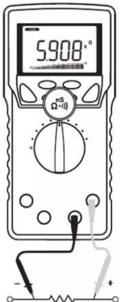
•)))
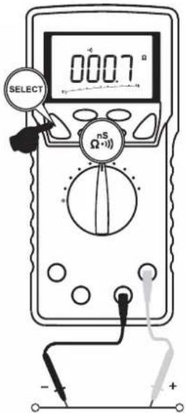
nS
Note:
• [nS] function does not show the bar graph.
- To avoid external noise influence, shield the object to measure with COM potential. Measurements with finger-touched test pins may cause some errors being influenced by human body conductance.
5-7 [Temp] (Max. rated input voltage: 50 mV dc)
- Temperature measurement (°C) or (°F) (For K-type thermocouple)
WARNING
- Pay attention in order to avoid risk of burn depending on the object temperature or measuring environment.
- Do not apply exceeding 50 mV to the measuring terminals.
1) What to measure
°C, °F (Temperature): Temperature of liquid, solids, gas, and etc.
2) Measuring ranges
Celsius: -50 °C to 1,000 °C
Fahrenheit: -58 °F to 1832 °F
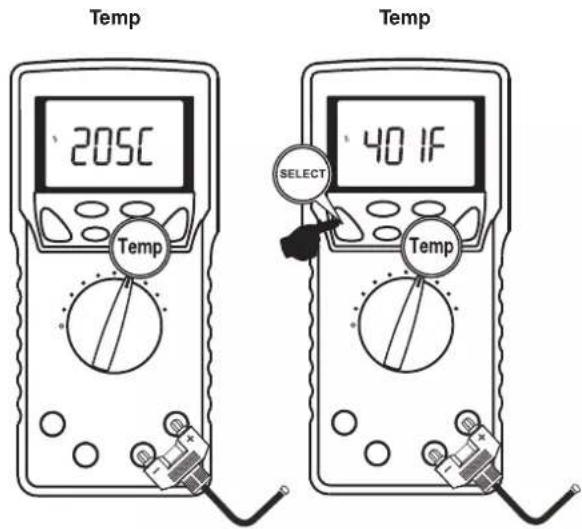
3) Measuring procedure
① Connect the provided K-type thermocouple to the Temp measuring terminal.
② Set the function selector to Temp.
③ Press the SELECT button to select °C or °F.
④ Apply the Thermocouple to the object to measure.
⑤ Read the display.
Note:
• Temperature function does not show the bar graph.
- The provided K-type thermocouple (K-250PC) is a polar device. Connect the device to the meter properly.
• The range of K-250PC is -50°C to 250 °C
- Separately available K-type adapter (K-AD) allows you to use other international standard mini plug thermocouples.
5-8 「─┬─┬─」(Do not apply any voltage or current.)
- Capacitance (−) measurement
• Diode (▶) test
WARNING
- Do not apply any voltage or current to the measuring terminals.
- Measuring live circuit may damage the meter.
5-8-1 Capacitance (H) measurement
CAUTION
- Discharge the capacitor before any measurement.
- The instrument applies the current to the capacitor to measure. Capacitors with large leakage such as chemical capacitors cannot be measured accurately.
1) What to measure - (Capacitance): Capacitance of capacitors
2) Measuring ranges -1:7 ranges; 60.00 nF, 600.0 nF, 6.000 μF, 60.00 μF, 600.0 μF, 6.000 mF, and 25.00 mF
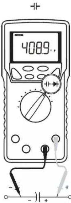
3) Measuring procedure ① Connect the red plug of the test lead to measuring terminal and the black one to the COM terminal. ② Set the function selector to , then press the SELECT button to select the capacitance measurement. (Unit "F" will be indicated.) ③ Apply the test pins (Red and Black) to the object to measure. ④ Read the display.
Note: - Capacitance function does not show the bar graph.
5-8-2 Diode (▶test
1) What to measure
(Diode test): Judging the diode (Good or defective)
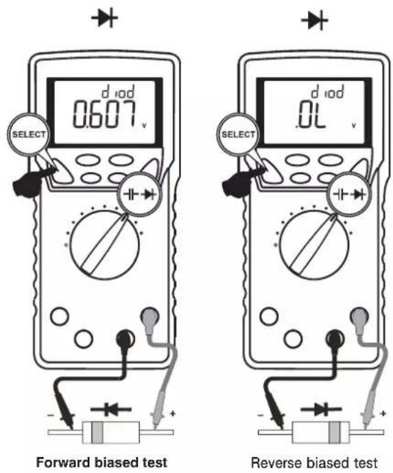
2) Measuring procedure
① Connect the red plug of the test lead to measuring terminal and the black one to the COM terminal.
② Set the function selector to -in press the SELECT button to select the diode test.
(The sub display shows [diod].)
③ Apply the black test pin to the cathode of the diode, and the red to the anode.
④ The display will show the forward voltage drop (forward biased).
*Forward biased voltage drop for a good silicon diode is between 0.400 V to 0.900 V. A reading higher than that indicates a defective diode. A zero (or close to)reading indicates a defective diode (shorted). An OL indicates a defective diode (open).
⑤ Apply the red test pin to the cathode of the diode, and the black one to the anode.
*A reading [OL] for reverse biased voltage drop indicates the diode is good. Any other readings indicate the diode is defective (resistive or shorted).
Note:
- Open circuit voltage between the measuring terminals: <3.5 V dc
• Test current: 0.4 mA (typical)
• Diode test function does not show the bar graph.
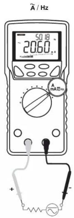
5-9
AmAHz , A_Hz
- DC current (m\\, \\, \\) measurement
- AC current (m , μ , ) / Frequency(Hz) simultaneous measurement
- DC current (m . . )/AC current (m . . ) simultaneous measurement
WARNING
- Do not apply any voltage to the measuring terminals.
- Be sure to connect the meter in series with the load object.
- Do not apply any input exceeding the max. rated current.
- First turn off the circuit to measure, then cut the part. Connect the test leads of the meter properly in series with the circuit.
Correct way
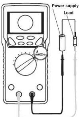
Wrong way
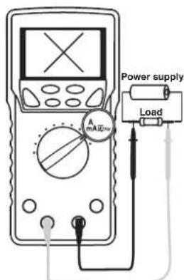
5-9-1 Current (mA/μA) measurement
(m , m , , Max. rated input current 600 mA dc/ac)
1) What to measure
· m , (DC current): DC circuit current
· m , (AC current): AC circuit current
· m /m , μ /μ (DC current component/AC current component)
• Hz (Frequency): Measuring current frequency
2) Measuring ranges
mA : 2 ranges; 60.00 mA and 600.0 mA A : 2 ranges; 600.0 A and 6000 A
3) Measuring procedure
① Set the function selector to in or Ain press the SELECT button to select [m] , [m/m] ,
[m / Hz] for mA range, or select [ [ / ], [ /Hz] for A range.
② Connect the red plug of the test lead to mA μA measuring terminal and the black one to the COM terminal.
③ Connect the test pins (red and black) in series with the circuit to measure.
- m\\,\\\overline{A}\$: Connect the black test pin to the lower electric potential side of the circuit to measure, and the red test pin to the higher electric potential side in series with the object.
- m/ : Connect the test pins (red and black) in series with the circuit to measure.
④ Read the display.
Note:
| Measuring Range | Frequency (Hz)Input sensitivity(Sine wave) | Frequency range |
| 600.0 μA 60 μA | 15.00 Hz ~ 3.000 kHz | |
| 6000 μA 600 μA | ||
| 60.00 mA 40 mA | ||
| 600.0 mA 60 mA | ||
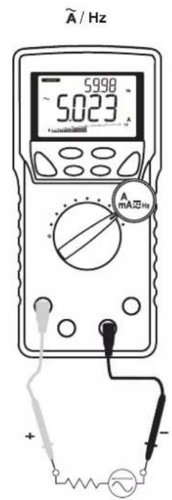
5-9-2 Current (A) measurement
( , Max. rated input current AC 10 A dc/ac )
1) What to measure
· (DC current): DC circuit current
• (AC current): AC circuit current
- / (DC current component / AC current component)
• Hz (Frequency): Measuring current frequency
2) Measuring ranges
2 ranges; 6.000 A and 10.00 A
3) Measuring procedure
① Set the function selector to , and press the SELECT button to
select a display style from [] , [/] , and [/Hz] .
② Connect the red plug of the test lead to A measuring terminal and the black one to the COM terminal.
③ Connect the test pins (red and black) in series with the circuit to measure.
- : Connect the black test pin to the lower electric potential side of the circuit to measure, and the red test pin to the higher electric potential side in series with the object.
- : Connect the test pins (red and black) in series with the circuit to measure.
④ Read the display.
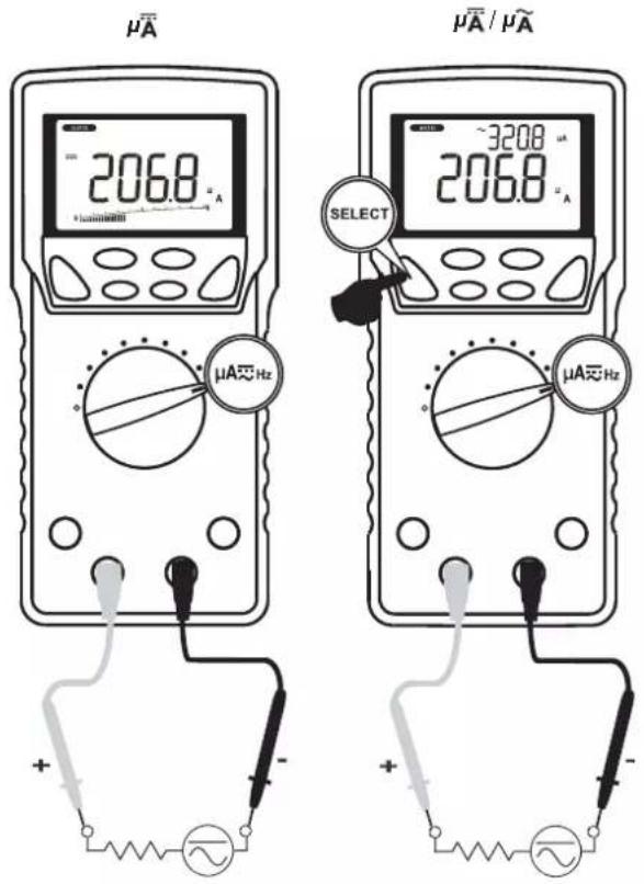
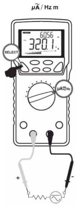
Note:
- >6 A: Cool down more than 3 minutes after measuring 1 minute.
< 6 A Continuable
| Measuring range | Frequency (Hz)Input sensitivity (Sine wave) | Frequency range |
| 6.000 A 4 | A | 15.00 Hz ~ 3.000 kHz |
| 10.00 A 7 | A |
5-10 Measurements with Separately Available Accessories
WARNING
- Do not apply any input exceeding max. rated input for the separately available accessories.
- Do not switch the function selector while measuring.
CAUTION
- To make measurements of consumption current for home appliances using a current probe, use a line separator as shown in the drawing below.
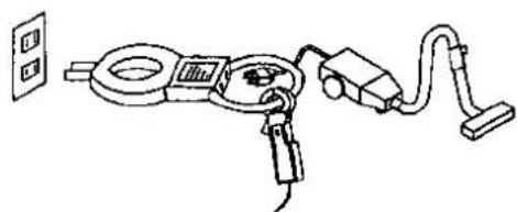
natural_image
Line drawing of a handheld electronic device with wires and components, no text or symbols present- Overall accuracy is calculated using the total of each probe's accuracy.
5-10-1 AC flexible clamp sensor: CL3000 (Max. measurable current 3000 A ac)
1) What to measure 50/60 Hz sine wave current such as consumption current of home appliances, current of power supply equipments, and etc.
2) Measuring ranges 30 A, 300 A, and 3000 A
3) Measuring procedure
① Connect the red plug of the current probe to the V measuring terminal and the black one to the COM terminal.
② Set the function selector to Hz, then press the SELECT button to select V /Hz.
③ Press the RANGE button to set the 9.999 V range.
④ Set the range selector knob on the current probe to the 30 A, 300 A, or 3000 A range.
⑤ Clamp the conductor under test with the flexible current probe.
⑥ Multiply the reading by 10 for 30 A range, by 100 for 300 A range, and by 1000 for 3000 A range respectively, and read in units of A (amps).
Note:
- Current exceeding 30 A, 300 A, or 3000 A cannot be measured. (Do not measure such high current even though the display works.)
- Try to put the conductor under test in the center of the flexible current probe as possible.
5-10-2 Clamp probe: CL-22AD
(Max. measurable current 200 A dc/ac)
1) What to measure
ACA: 50/60 Hz sine wave current such as consumption current of home appliances, current of power supply equipments, and etc.
DCA: Current of automotive electric circuits, consumption current of DC equipments, etc.
2) Measuring ranges
20 A and 200 A
3) Measuring procedure
① Connect the red plug of the current probe to the V measuring terminal and the black one to the COM terminal.
② To make DC current measurement (DCA), set the function selector to and press the SELECT button to select mV, then press the RANGE button to set 600.0 mV range.
To make AC current measurement (ACA), set the function selector to and press the SELECT button to select mVHz, then press the RANGE button to set 600.0 mV range.
③ Set the range selector knob on the current probe to the 20 A range or 200 A range.
*Before making DC current measurement, turn the Center Adjuster knob to make the reading zero.
④ Open the clamp jaws of the clamp probe and clamp the wire to measure.
⑤ Multiply the reading by 0.1 for 20 A range, and read the display directly for 200 A range.
Note:
- Current exceeding 20 A or 200 A cannot be measured.
(Do not measure such high current even though the display works.) - Try to put the wire to measure in the center of the clamp jaws as possible.
5-10-3 DC Clamp probe: CL-33D
(Max. measurable current 300 A dc)
1) What to measure
Current of automotive electric circuits, consumption current of DC equipments, etc.
2) Measuring ranges
30 A and 300 A
3) Measuring procedure
① Connect the red plug of the current probe to the V measuring terminal and the black one to the COM terminal.
② Set the function selector to % m and press the SELECT button to select m , then press the RANGE button to set 600.0 mV range.
③ Set the range selector knob on the current probe to the 30 A range or 300 A range.
*Before making DC current measurement, turn the Center Adjuster knob to make the reading zero.
④ Open the clamp jaws of the clamp probe and clamp the wire to measure.
⑤ Multiply the reading by 0.1 for 30 A range, and read the display directly for 300 A range.
Note:
- Current exceeding 30 A or 300 A cannot be measured.
(Do not measure such high current even though the display works.) - Try to put the wire to measure in the center of the clamp jaws as possible.
5-10-4 Temperature probe: T-300PC
1) What to measure
Temperature of liquid, solids, gas, and etc.
Note:
To make temperature measurement, connect the temperature probe to the PC710 connected to the PC on which sanwa's software PC Link7 is installed and running.
2) Measuring range
-50 \~ 300 ℃
DMM range: 6 kΩ
3) Measuring procedure
① Connect the red plug of the temperature probe to ^ns measuring terminal and the black one to the COM terminal.
② Set the function selector to ^nS and press the SELECT button to select [] .
③ Press the RANGE HOLD button to set 6 kΩ.
① Apply the thermocouple to the object to measure.
⑤ Read the measurements on the information window of the PC Link7.
⑥ Remove the thermocouple from the object.
5-10-5 Other separately available products
The meter also works with the following separately-available products.
LS11, K-AD, CL124, CL140, K-8-250, K-8-300, K-8-500, K-8-650,
K-250PC/K-250CD, and K-8-800
[6] MAINTENANCE
WARNING
- The followings are important to safety. Read this manual throughly to maintain the instrument.
- Calibrate and inspect the instrument at least once a year to ensure safety and maintain its accuracy.
6-1 Simple Examination
1) Appearance
- Check for damaged appearance by dropping down and so on.
2) Test leads
- Check for loose contacts between the measuring terminals and test lead plugs.
- Check for damaged test lead wires.
- Check for exposed core wire anywhere on the test leads.
If you find any problem on the above items, stop using immediately and ask us to repair it.
Check for the test leads without breaking wires, referring to the section 5-1.
6-2 Calibration
If self-diagnostic message "rE-O" is being displayed while powering on, the meter is re-organizing internal parameters. Do not turn off the meter, and it will be back to normal measurement shortly. However, if self-diagnostic message "C_Er" is being displayed while powering on, some meter ranges might be largely out of specifications. To avoid misleading measurements, stop using the meter and send it for re-calibration. Refer to the AFTER-SALE SERVICE section for obtaining warranty or repairing service.
For requesting calibration and inspection, contact an authorized agent/distribution service provider, listed in our website. See section 7-3.
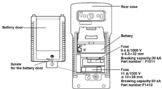
6-3 Battery and Fuse Replacement
WARNING
- Do not open the rear case with live measuring terminals to avoid electric shock. Also, make sure the meter power is OFF, before starting replacement.
- Be sure to use the specified fuse. Neither use unspecified fuse nor short-circuit the fuse holder.
Pre-installed battery
Since the pre-installed battery is for monitoring, it may not be durable as typically expected.
*The purpose of the battery for monitoring is to check for the functions and performances of the product.
Replacement procedure
① Remove the holster and loosen the Philips-head screw fixing the battery door using appropriate screw driver.
② Remove the battery door and replace the battery or fuse with new one.
③ Re-fasten the screw and set the holster again.
6-4 Storage

CAUTION
- The panel and case are not resistant to volatile solvents. Do not wipe out with solvents or isopropyl alcohol. Clean the instrument up with a dry soft cloth.
- The panel and case are not resistant to heat. Keep it away from heat-generating devices such as solder irons.
- Do not save the instrument into vibratory places or where the instrument may fall off.
- Do not expose the instrument to direct sunlight and do not save it into any places with extreme temperature, humid, or condensation.
- Remove the battery for saving the instrument over a long period of time.
Save the instrument into an appropriate place, according to the precautions above.
[7] AFTER-SALE SERVICE
7-1 Warranty and Provision
Sanwa offers comprehensive warranty services to its end-users and to its product resellers. Under Sanwa's general warranty policy, each instrument is warranted to be free from defects in workmanship or material under normal use for the period of one (1) year from the date of purchase.
This warranty policy is valid within the country of purchase only, and applied only to the product purchased from Sanwa authorized agent or distributor.
Sanwa reserves the right to inspect all warranty claims to determine the extent to which the warranty policy shall apply. This warranty shall not apply to disposables batteries, or any product or parts, which have been subject to one of the following causes:
- A failure due to improper handling or use that deviates from the instruction manual.
- A failure due to inadequate repair or modification by people other than Sanwa service personnel.
- A failure due to causes not attributable to this product such as fire, flood and other natural disaster.
- Non-operation due to a discharged battery.
- A failure or damage due to transportation, relocation or dropping after the purchase.
7-2 Repair
Customers are asked to provide the following information when requesting services:
- Customer name, address, and contact information
- Description of problem
- Description of product configuration
- Model Number
- Product Serial Number
- Proof of Date-of-Purchase
- Where you purchased the product
Please contact Sanwa authorized agent / distributor / service
provider, listed in our website, in your country with above information. An instrument sent to Sanwa / agent / distributor without above information will be returned to the customer.
Note:
1) Prior to requesting repair, please check the following: Capacity of the built-in battery, polarity of installation and discontinuity of the test leads.
2) Repair during the warranty period:
The failed meter will be repaired in accordance with the conditions stipulated in 7-1 Warranty and Provision.
3) Repair after the warranty period has expired:
In some cases, repair and transportation cost may become higher than the price of the product. Please contact Sanwa authorized agent / service provider in advance.
The minimum retention period of service functional parts is 6 years after the discontinuation of manufacture. This retention period is the repair warranty period. Please note, however, if such functional parts become unavailable for reasons of discontinuation of manufacture, etc., the retention period may become shorter accordingly.
4) Precautions when sending the product to be repaired: To ensure the safety of the product during transportation, place the product in a box that is larger than the product 5 times or more in volume and fill cushion materials fully and then clearly mark "Repair Product Enclosed" on the box surface. The cost of sending and returning the product shall be borne by the customer.
7-3 SANWA web site
http://www.sanwa-meter.co.jp
E-mail: exp_sales@sanwa-meter.co.jp
[8] SPECIFICATIONS
8-1 General Specifications
| Operation method | Delta-sigma modulation | |
| LCD display | Main display | 9,999 counts:DCV, ACV, Logic-Level Frequency(Hz),nS, Duty Cycle, and Temperature6,000 counts:DCmV, ACmV, Resistance, Continuity,Capacitance, DCA, DCmA, DCμA,ACA, ACmA, and ACμA2,000 counts: DiodeBar graph: Up to 41 segments |
| Sub display | 9,999 counts: ACV, Frequency (Hz)6,000 counts: ACmV, ACA, ACmA,and ACμA | |
| Over-range indication | Over-range input tums on "OL" indicator at the numeric part. | |
| Sampling rate | Numeric part $ times / sec. | |
| Bar graph part 60 times / sec. | ||
| Low battery indication | Decreasing the internal battery voltage to approx.7 V turns the battery mark on. | |
| Operating conditions | Altitude: < 2,000 m Pollution degree: II | |
| Operating temperature/humidity | 5 °C to 40 °C : non-condensing5 °C to 31 °C : 80%RH (Max.)31 °C to 40 °C : decreasing 80 % to 50 % linearly | |
| Storage temperature/humidity | -10 °C to 40 °C : 80 %RH (Max.) non-condensing(with battery removed)40 °C to 50 °C : 70 %RH (Max.) non-condensing(Remove the battery, if the equipment is not goingto be used for a long time.) | |
| Temperature coefficient | 0.15 x (accuracy @23 ±5 °C)/ °C @(0 °C to 18 °C or28 °C to 40 °C ) | |
| Power source | Single manganese 9 V battery 6LR61(IEC6LF22, NEDA1604A) | |
| AC sensing method | True RMS (AC coupling) | |
| Auto Power Saving | Approx. 30 minutes after the last operation | |
| Safety Compliances | IEC61010-1, IEC61010-2-030, IEC61010-2-033IEC61010-031 | |
| V Hz ΩTempnS + - + | Category II for 1000 V ac and dcCategory III for 600 V ac and dc | |
| mAμA | ||
| A | ||
| EMC | Meets EN61326-1:2006In an RF field of 3 V/m:Capacitance function is not specifiedOther function ranges:Total Accuracy = ± (Specified% rdg + 100 digits)Performance above 3 V/m is not specified | |
| Dimensions | without holster Approx. L 175 mm×W80 mm×H40 mm | |
| with holster Approx. L 184 mm×W86 mm×H52 mm | ||
| Mass | without holster Approx. 360 g | |
| with holster Approx. 430 g | ||
| Power consumption | Approx. 48 mW / approx. 0.45 mW (Auto Power Saving) | |
| Battery life | Approx. 60 hours (DCV measurement) | |
| Accessories | Test leads (TL-23a),Holster (H-700) with light shielding magnet cap,K-type thermocouple (K-250PC),Instruction manual | |
OVERVOLTAGE CATEGORY
Equipment of CAT II: Primary cable runs of power-consuming equipments from a wall socket.
Equipment of CAT III: Primary cable runs of equipments directly connected to a distribution board and cable runs from a distribution board to wall sockets.
Equipment of CAT IV: Cable runs from an incoming line to a distribution board.
8-2 Measuring Range and Accuracy
Accuracy: ±(% rdg + dgt)
rdg: reading, dgt: least significant digit
Temperature: 23 °C ±5 °C, Humidity: <75 % R.H.
True RMS voltage and current accuracies are specified from 10 % to 100 % of each range otherwise specified.
Crest factor: < 2:1 (at full scale), < 4:1 (at half scale)
DC Voltage DCV
DC voltage (DCV) for single display
| Range Accuracy | |
| 60.00 mV ± | (0.12 % rdg + 2 dgt) |
| 600.0 mV ± | (0.06 % rdg + 2 dgt) |
| 9.999 V, 99.99 V, 999.9 V ± | (0.08 % rdg + 2 dgt) |
DC/AC Voltage (DC/AC V) for dual display
| Range Accuracy | |
| 60.00 mV, 600.0 mV9.999 V, 99.99 V, 999.9 V | ± (0.7 % rdg + 6 dgt) |
Input impedance: 10 MΩ, 80 pF nominal
(130 pF nominal for 600.0 mV & 60.00 mV range)
AC Voltage ACV
AC voltage (ACV)/ Frequency (Hz) for dual display
| Range Accuracy | |
| 50 Hz ~ 60 Hz | |
| 60.00 mV, 600.0 mV, 9.999 V, 99.99 V, 999.9 V | ± (0.5% rdg + 3 dgt) |
| 40 Hz ~ 500 Hz (Except 50 Hz ~ 60 Hz) | |
| 60.00m V, 600.0 mV ± (0.8% rdg + 4 dgt) | |
| 9.999 V, 99.99 V ± (1.0% rdg + 4 dgt) | |
| 999.9 V ± (2.0% rdg + 4 dgt) | |
| 500 Hz ~ 1 kHz | |
| 60.00 mV, 600.0 mV ± (2.0% rdg + 3 dgt) | |
| 9.999 V, 99.99 V ± (1.0% rdg + 4 dgt) | |
| 999.9 V ± (2.0% rdg + 4 dgt) | |
| 1 kHz ~ 3 kHz | |
| 60.00 mV, 600.0 mV ± (2.0% rdg + 3 dgt) | |
| 9.999 V, 99.99 V, 999.9 V ± (3.0% rdg + 4 dgt) | |
| 3 kHz ~ 20 kHz | |
| 60.00 mV *, 600.0 mV * ± (2.0% rdg + 3 dgt) | |
| 9.999 V **, 99.99 V ± 3 dB | |
| 999.9 V Unspecified | |
Input impedance: 10 MΩ, 80 pF nominal
(130 pF nominal for 600.0 mV & 60.00 mV range)
Residual reading: Less than 5 digits with test leads shorted
* Specified from 30 % to 100 % of the range
** 3 kHz to 15 kHz
DC/AC Voltage (DC/AC V) for dual display
| Range Accuracy | |
| 50 Hz ~ 60 Hz | |
| 60.00 mV, 600.0 mV | ± (0.7 % rdg + 6 dgt) |
| 9.999 V, 99.99 V, 999.9 V | |
| 40 Hz ~ 1 kHz (Except 50 Hz ~ 60 Hz) | |
| 60.00 mV, 600.0 mV ± (1.0 % rdg + 6 dgt) | |
| 9.999 V, 99.99 V, 999.9 V ± (2.2 % rdg + 6 dgt) | |
| 1 kHz ~ 20 kHz | |
| 60.00 mV, 600.0 mV ^1) | ± (2.2 % rdg + 6 dgt) |
| 9.999 V ^2) , 99.99 V ±3 dB | |
| 999.9 V Un specified | |
Input impedance: 10 MΩ, 80 pF nominal
(130 pF nominal for 600.0 mV & 60.00 mV range)
1) Specified from 30 % to 100 % of the range
2) 3 kHz \~ 15 kHz
DC current (DCA)
| Range Accuracy Input resistance** | ||
| 600.0 μA | ± (0.2 % rdg + 4 dgt) | Approx. 83 Ω |
| 6000 μA | ||
| 60.00 mA | Approx. 1 Ω | |
| 600.0 mA | ||
| 6.000 A | Approx. 0.005 Ω | |
| 10.00 A* | ||
* > 6 A: Cool down more than 3 minutes after measuring 1 minute.
< 6 A Continuable
**Fusing resistor not included
AC current (ACA), DC/AC current (DC/AC A)
| Range Accuracy Input resistance** | ||
| DC, 50 Hz ~ 60 Hz | ||
| 600.0 μA | ± (0.6 % rdg +3 dgt) | Approx. 83 Ω |
| 6000 μA | ||
| 60.00 mA | Approx. 1 Ω | |
| 600.0 mA ± | (1.0 % rdg +3 dgt) | |
| 6.000 A10.00 A* | ± (0.8 % rdg +6 dgt) | Approx. 0.005 Ω |
| 40 Hz ~ 1 kHz (Except 50 Hz ~ 60 Hz) | ||
| 600.0 μA6000 μA | ± (0.8 % rdg +4 dgt) | Approx. 83 Ω |
| 60.00 mA | Approx. 1 Ω | |
| 600.0 mA ± | (1.0 % rdg +4 dgt) | |
| 6.000 A10.00 A* | ± (0.8 % rdg +6 dgt) | Approx. 0.005 Ω |
* > 6 A: Cool down more than 3 minutes after measuring 1 minute.
< 6 A Continuable
**Fusing resistor not included
Resistance (Ω)
| Range Accuracy | |
| 600.0 Ω 6.000 kΩ,60.00 kΩ, 600.0 kΩ | 0.1 % rdg + 3 dgt |
| 6.000 MΩ 0.4 % rdg | + 3 dgt |
| 60.00 MΩ 1.5 % rdg | + 5 dgt |
| 99.99 nS 0.8 % rdg+ | 10 dgt |
Open circuit voltage: <1.2 Vdc (<1.0 Vdc for 60.00 MΩ range)
Temp (°C & °F)**
| Range Accuracy* | |
| -50°C ~ 1000°C | 0.3% rdg + 2°C |
| -58°F ~ 1832°F 0.3% rdg + 5 | °F |
* Accuracy with K-type thermocouple K-type thermocouple range and accuracy not included
**Cool down more than 30 minutes after measuring DCA or ACA.
Frequency (Hz)
| Measuring ranges Input sensitivity* Frequency ranges | ||
| 60.00 mV 40 mV | 15.00 Hz ~ 50.00 kHz | |
| 600.0 mV 60 mV | ||
| 9.999 V 2.5 V | 15.00 Hz ~ 10.00 kHz9 | |
| 999.9 V | 100 V | |
| 600.0 μA | 60 μA | 15.00 Hz ~ 3.000 kHz |
| 6000 μA | 600 μA | |
| 60.00 mA 40 mA | ||
| 600.0 mA 60 mA | ||
| 6.000 A | 4 A | |
| 10.00 A | 7 A | |
Accuracy: ±(0.04 % rdg + 4 dgt)
*Specified based on sine wave RMS
Logic level frequency (MHz) and Duty cycle (D%)
| DCmV function | Range | Accuracy* |
| Frequency | 5.000 Hz ~ 1.000 MHz | ± (0.03 %rdg + 4 dgt) |
| Duty cycle | 0.00 % ~ 100.0 % | ± (3 dgt/kHz + 2 dgt)** |
* Input sensitivity: Square wave more than 2.5 V
(3 V and 5 V logic family)
** Frequency range: 5 Hz to 10 kHz
Capacitance
| Range Accuracy* | |
| 60.00 nF, 600.0 nF*** ± | (0.8 % rdg + 3 dgt) |
| 6.000 μF ± | (1.0 % rdg + 3 dgt) |
| 60.00 μF ± | (2.0 % rdg + 3 dgt) |
| 600.0 μF ** ± | (3.5 % rdg + 5 dgt) |
| 6.000 mF ** ± | (5.0 % rdg + 5 dgt) |
| 25.00 mF ** ± | (6.5 % rdg + 5 dgt) |
* Accuracies with film capacitor or better
** In manual-ranging mode, measurements not specified below 50.0 μF, 0.54 mF and 5.4 mF for 600.0 μF, 6.000 mF and 25.00 mF ranges respectively
*** In manual-ranging mode, the accuracy for measurements below 5.4 nF for 60.00 nF range and 54 nF for 600.0 nF range is: ±(0.8 % rdg + 6 dgt)
Diode test
| Range A | Accuracy Test current | Open circuit voltage | |
| 2.000 V ± (1 % rdg +1 dgt) | Approx. 0.4 mA | < 3.5 V | |
Continuity check •»)
Threshold level: 20 Ω to 300 Ω
Response time: < 100 μs
Non-Contact EF-Detection
| Typical Voltage | Tolerance EF-Strength Indication | |
| 20 V 10 V | ~ 36 V | — |
| 55 V 23 V | ~ 83 V | — — |
| 110 V 59 V | ~ 165 V | — — — |
| 220 V 124 V | ~ 330 V | — — — — |
| 440 V 250 V | or more | — — — — — |
Indication: EF-Strength indication and audible beep tones are proportional to the field strength. (Stronger EF makes the period of intermittent beep tones shorter.)
Detection Frequency: 50/60 Hz
Detection Antenna: Top end of the meter
Probe-Contact EF-Detection:
For more precise indication of live wires, such as distinguishing between live and ground connections, use the red (+) test probe for direct contact measurement.
Max/Min (with capture mode)
Accuracy: ± (Specified % rdg + 250 dgt) in each function
Sampling time: Approx. 1 ms
Max/Min (with recording mode)
Accuracy: ± (Specified % rdg + 10 dgt) in each function
(for changes > 100 ms in duration in voltage or current measurement)
How to calculate an accuracy
Example) DC voltage measurement (DC mV)
True value: 100.0 [mV]
Range accuracy: ±(0.06 %rdg+2 dgt) in the 600.0 mV range
Measuring error: ±(100.0 [mV]×0.06 % rdg +2 dgt)
$$ \doteq \pm 0. 3 [ \mathrm{mV} ] $$
Calculation: 100.0 [mV] ±0.3 [mV]
Reading: 099.7 [mV] to 100.3 [mV]
* 2 dgt in the 600.0 mV range corresponds to 0.2 mV.
The product specifications and its appearance described in this manual are subject to change without prior notice for improvements or other reasons.
sanwa®
三和電気計器株式会社
- [1] SAFETY PRECAUTIONS
- [2] APPLICATIONS AND FEATURES
- [3] Parts Identification
- [4] DESCRIPTION OF FUNCTIONS
- [5] Measuring procedures
- [6] MAINTENANCE
- [7] AFTER-SALE SERVICE
- \*Before use, read the following safety precautions.
- 1-1 Explanation of Warning Symbols
- 1-2 Warning Instructions for Safe Use
- WARNING
- CAUTION
- 2-1 Applications
- 2-2 Features
- Note:
- 3-2 Display
- 4-1 Power Switch/Function Selector
- 4-2 Auto Power Saving
- 4-2-2 How to disable the Auto Power Saving
- 4-3 Low Battery Indication
- 4-4 Measuring Function Selection
- 4-5 EF (Electric Field) Detection
- 4-6 Range Hold
- 4-7 DH Data Hold
- 4-8 Beeper Control
- 4-9 PC (Personal Computer) Interface
- 4-10 Test Leads Improper Connection Warning
- 4-11 CAPTURE Crest capture mode (Sampling time: 1 ms)
- 4-12 REC MAX/MIN/AVG Recording Mode
- 4-13 △ Relative Measurement
- 4-14 Back Light
- 4-15 Terms
- Analog bar graph
- True RMS
- Crest Factor
- 5-1 Pre-operational Check
- 5-6 nS (Do not apply any voltage or current.)
- 1) What to measure
- 2) Measuring ranges
- 5-7 [Temp] (Max. rated input voltage: 50 mV dc)
- 5-8-2 Diode (▶test
- 5-9-1 Current (mA/μA) measurement
- 5-9-2 Current (A) measurement
- 5-10 Measurements with Separately Available Accessories
- 5-10-1 AC flexible clamp sensor: CL3000 (Max. measurable current 3000 A ac)
- 5-10-2 Clamp probe: CL-22AD
- (Max. measurable current 200 A dc/ac)
- 5-10-3 DC Clamp probe: CL-33D
- (Max. measurable current 300 A dc)
- 5-10-4 Temperature probe: T-300PC
- 5-10-5 Other separately available products
- 6-1 Simple Examination
- 6-2 Calibration
- 6-3 Battery and Fuse Replacement
- Pre-installed battery
- Replacement procedure
- 6-4 Storage
- 7-1 Warranty and Provision
- 7-2 Repair
- 7-3 SANWA web site
- [8] SPECIFICATIONS
- OVERVOLTAGE CATEGORY
- 8-2 Measuring Range and Accuracy
- DC Voltage DCV
- AC Voltage ACV
- Continuity check •»)
- Max/Min (with capture mode)
- Max/Min (with recording mode)
- How to calculate an accuracy
- sanwa®
- 三和電気計器株式会社
Brand : Sanwa
Model : PC710
Category : Multimeter