DPR-901II - Uncategorized BSS Audio - Free user manual and instructions
Find the device manual for free DPR-901II BSS Audio in PDF.


| Product Type | Dynamic Processor (Compressor/Limiter/Expander/Gate) |
| Form Factor | 19-inch rackmount, 1U |
| Channels | 2 (Dual Mono/Stereo) |
| Frequency Response | 20 Hz - 20 kHz (±0.5 dB) |
| Dynamic Range | >110 dB |
| Threshold Range | -40 dBu to +20 dBu |
| Compression Ratio | 1:1 to ∞:1 (variable) |
| Attack Time | 0.1 ms to 200 ms |
| Release Time | 50 ms to 3 s (auto or manual) |
| Input Impedance | >10 kΩ (balanced) |
| Output Impedance | 60 Ω (balanced) |
| Maximum Input Level | +24 dBu |
| Maximum Output Level | +24 dBu |
| Power Supply | 100-240 V AC, 50/60 Hz, 20 W |
| Dimensions (W x H x D) | 483 x 44 x 200 mm (19 x 1.73 x 7.87 in) |
| Weight | 3.5 kg (7.7 lbs) |
| Controls | Threshold, Ratio, Attack, Release, Gain, Bypass, Stereo Link, Sidechain |
| Indicators | Gain Reduction (10-segment LED), Output Level, Status LEDs |
| Connectors | XLR (balanced input/output), 1/4" TRS (sidechain insert) |
| Cleaning | Use a dry, soft cloth. Avoid solvents and abrasive cleaners. |
| Safety | Do not expose to moisture; disconnect power before cleaning or servicing. |
| Accessories (included) | Power cord, rackmount ears, user manual |
Frequently Asked Questions - DPR-901II BSS Audio
User questions about DPR-901II BSS Audio
0 question about this device. Answer the ones you know or ask your own.
Ask a new question about this device
Download the instructions for your Uncategorized in PDF format for free! Find your manual DPR-901II - BSS Audio and take your electronic device back in hand. On this page are published all the documents necessary for the use of your device. DPR-901II by BSS Audio.
USER MANUAL DPR-901II BSS Audio
DPR-901ii User's Manual
This Manual is the COPYRIGHT of BSS Audio. All reproduction and copying, other than for the legal owner's personal use, or disclosure of part or whole to a third party, without prior written authorisation, is in violation of the European Copyright Convention. BSS Audio 1995
Welcome to the DPR-901ii Users Manual
DPR-901ii ABOVE AND BELOW THRESHOLD DYNAMIC PARAMETRIC EQUALISATION.
This manual is provided with the aim of assisting sound engineers, producers, musicians, system installers and consultants to fully understand the DPR-901ii, and to benefit from it's maximum capability.
As opposed to most manuals, the contents can be read like a book. At the same time, the information is structured under a series of broad headings for easy access. So where possible within each section:
●The most immediate information appears at the head of each section under the main title.
- As you read further into each subsequent section, more detailed, specific information is given.
If you have any comments or questions about installing, setting-up or using the DPR-901ii, please write to us about your application, at the address in the warranty section.
CE This equipment has been tested and found to comply with the following European Standards for Electromagnetic Compatibility.
Emission Specification EN55013 1990 (Associated equipment)
Immunity Specification EN50082/1 1992 (RF Immunity, Fast
Transients and ESD)
Mains Disturbance EN61000/3/2 1995
For continued compliance ensure that all input and output cables are wired with cable screen connected to pin 1 of the XLR. The input XLR pin 1 on BSS equipment is generally connected to chassis via a capacitor to prevent ground loops whilst ensuring good emc compatibility.
Table Of Contents
Table Of Contents
1.0 Introduction 4
1.1 Features and Facilities 5
2.0 Installation 6
2.1 Unpacking 6
2.2 Mechanical Installation 6
2.3 Mains Power 7
2.4 Voltage Setting 8
2.5 Safety Earthing 8
2.6 AC Power Fusing 8
2.7 Audio Connections 9
2.8 Ground Loop Control 10
3.0 Controls 11
4.0 Principle of operation 16
5.0 Using the DPR-901ii 18
6.0 Warranty Information 20
Appendix A 21
A1 Chassis/0v Link Removal 21
A2 Input pin 1 to Chassis Connection 22
A3 Transient Suppressor Replacement 22
Appendix B 23
Technical Specifications 23
Appendix C 25
Glossary 25
User Notes 28
1.0 Introduction
Congratulations!. Whether you're a sound engineer, producer, consultant, installer or musician, you've just added a powerful new weapon to your audio armoury.
The DPR-901ii is a new class of audio equaliser. Both subtle and powerful, it builds on the established problem solving capabilities of parametric equalisers.
It's uses range from processing and sweetening speech, instruments and composite music, through SPL control, to loudspeaker system and room tuning. The DPR-901ii refines the EQ process, makes it more specific - and expands it too.
For the first time, changes in EQ and signal dynamics at the EQ'd frequency can be created which are triggered either above or below the individual threshold levels in four adjustable frequency bands. The changes in tonality can range from the subtle and highly specific, up to the extremes of instrument effects. Either way, the DPR-901ii's unique subtractive process coupled with state-variable equalisation ensures uncoloured, low distortion sound. Group delay in particular is low and uniform, maintaining vital accuracy in the time/transient domain that is lacking in the majority of conventional equalisers with 'Bell' response envelopes.
1.1 Features and Facilities
The DPR-901ii is a four band parametric equaliser which varies the degree of equalisation dynamically, as the program level changes. The process can be thought of as frequency selective compression and/or expansion, but it is fundamentally different to simple 'frequency-conscious' dynamics processing as used for noise gating, de-essing and the like. It is also very different to the growing family of 'sliding filter' techniques used in single-ended noise reduction processors. A split facility allows the unit to be used as two separate two band units, and a side chain listen button allows monitoring of the filter setup.
Frequency selective compression is equivalent to applying CUT on a normal equaliser while frequency selective expansion is like applying BOOST. However, the DPR-901ii can be more subtle as the process is dynamic: it will only occur above (or below) the threshold you have set. Some possible uses for the DPR-901ii technology can be:
● To selectively compress and/or expand, broad or narrow-band segments of program.
●To de-ess and de-pop.
●To add dynamic loudness control (eg. bass boost at low SPLs).
●To control SPL in a dynamic and frequency conscious manner.
- To enhance or ‘sweeten’ mixed programme.
●To improve voice intelligibility (without risking how round or feedback).
●To enhance low level vocals.
● To correct for and/or guard against, bad microphone technique (by unskilled performers).
And in common with other units in BSS Audio's processor range, the DPR-901ii features:
●Friendly rotary control knobs for all parameter adjustments.
●Excellent low level resolution to maintain subtle musical detail.
●Minimum phase and low group delay for any EQ setting.
●High headroom >+ 20dBu.
●Conservative drive capability into low impedances (down to 600 ohms) and long, highly capacitive cables.
●Automatic relay controlled signal bypass if mains power is disconnected or fails.
Altogether, the DPR-901ii will not degrade a conventional high quality analogue signal processing chain, even when two units are inserted in line with the composite stereo mix.
2.0 Installation
2.1 Unpacking
As part of BSS AUDIO's system of quality control, this product is carefully checked before packing, to ensure flawless appearance.
After unpacking the unit, please inspect for any physical damage and retain the shipping carton and all relevant packing materials for use should the unit need returning.
A packet of spare fuses is supplied. Please keep them in a safe place.
If any damage has occurred, please notify your dealer immediately, so that a written claim for damages can be initiated. See the Warranty section of this manual.
2.2 Mechanical Installation
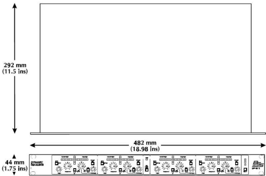
A vertical rack space of 1U (1.75", 44.5mm) is required. Figure 2.1 details the relevant dimensions and fixing centres.
If the unit is part of a transportable system, you must support the unit at it's rear by additional bracing or shelving. Failure to do so will impair reliability and invalidate the Warranty. Additional threaded M3 screw holes are provided on the rear sides to assist in providing proper support.
Adequate ventilation must be provided for by allowing sufficient room around the sides and rear of the unit to allow free circulation of air. Forced cooling is not required.
Fig. 2.1 Mechanical Dimensions
The internal power supply regulators are mounted on the case sides and use this as their heatsink. After a period of time in an enclosure, the metal case will feel hot to the touch, but this is quite normal and should not be a cause for alarm.
2.3 Mains Power
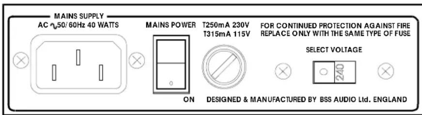
Before connecting your unit to its AC power source, check that the voltage selector switch located on the rear panel is correctly set.
See figure 2.2.
WARNING: THIS APPLIANCE MUST BE EARTHED.
IMPORTANT: The wires in this mains lead are colour coded in accordance with the following code:
Green and yellow.....Earth
Blue.....Neutral
Brown.....Live
As the colours of the wires in the mains lead of this appliance may not correspond with the coloured markings identifying the terminals in your plug, proceed as follows:
The wire which is coloured green and yellow must be connected to the terminal in the plug which is marked with the letter 'E' or by the earth symbol ± , or coloured green and yellow.
The wire which is coloured blue must be connected to the terminal which is marked with the letter 'N' or coloured black.
The wire which is coloured brown must be connected to the terminal which is marked with the letter 'L' or coloured red.
Those units that are supplied to the North American market will have an integral moulded 3 pin connector which is provided to satisfy the area safety standards.
Fig. 2.2 Mains Voltage Switch and Fuse
Voltage Setting Safety Earthing AC Power Fusing
2.4 Voltage Setting
The mains voltage selector switch provides a simple external adjustment to allow operation on all international AC power standards. The allowable ranges for the supply voltage are:
96VAC up to 132VAC on the 115V position and
195VAC up to 264VAC on the 230V position.
An additional internal tap change is available for 100V working. Refer to Appendix A.2. The tap change gives:
90VAC up to 110VAC on the 120V position
Outside these ranges the unit will not work satisfactorily, if at all. Voltages in excess of the maximum will probably cause damage. Voltages below the minimum will cause the power supplies to drop out of regulation, degrading the performance of the system.
2.5 Safety Earthing
The Green and Yellow wire of the mains cord must always be connected to an installation Safety Earth or Ground. The Earth is essential for personal safety as well as the correct operation of the system, and is internally connected to all exposed metal surfaces. Any rack framework into which this unit may be mounted is assumed to be connected to the same grounding circuit.
2.6 AC Power Fusing
The incoming mains power is fused within the DPR901ii by the fuse holder mounted on the rear panel. Should it be necessary, the fuse must be replaced by one of the same size and current rating.
20mm T250mA for the 230V setting
20mm T315mA for the 115V setting
It is most important for continued safety that this specification is strictly adhered to. Spare fuses of the correct rating are supplied with the unit from new.
It is unlikely that the AC fuse will fail during normal use and caution should be exercised if it does. The most likely reason at first power up is the incorrect setting of the mains voltage switch on the rear panel. Alternatively the unit may have been connected across two lines of a three phase supply. In both of these cases the internal transient suppressors may have been damaged and will continue to blow replacement fuses, even if the supply is now correct. The suppressors will have protected the DPR-901ii from damage and need replacing before the unit can be used again.
Refer to Appendix A.1 for the replacement procedure.
Audio Connections
2.7 Audio Connections
The DPR-901ii audio inputs are RFI filtered and electronically balanced, with the outputs electronically balanced and floating. They are designed to operate at any signal level up to +20dBu and will drive into loads of 600 ohms or greater. They will be 'fuss free', regardless of your installation's complexity. Figure 2.3 shows the connector wiring.
Balanced Wiring
Whether your system is wired to a 'pin 3 hot' or a 'pin 2 hot' convention will not matter as long as your wiring to both the input and output 3 pin XLR connectors are the same. As is common with all other BSS equipment of this type, we follow the convention of 'screen goes forward with the signal'. Input cable screening therefore needs to be derived from the signal source end as pin 1 is ground lifted at low frequencies for the inputs. If you wish to alter this please see appendix. You should use high quality audio cable with 2 cores + screen for low noise and reliability, and to sidestep potential problems.
Unbalanced Wiring
If the equipment driving the DPR-901ii has unbalanced outputs then you will need to add a wire jumper such that the screen connection on Pin 1 of the XLR is shorted to either Pin 2 or Pin 3, depending on system convention.
If the equipment being connected to the DPR-901ii outputs have only unbalanced inputs, then we recommend that you still use a balanced (ie. 2 core shielded) cable. You should connect the shield to pin 1, whilst the cold connection should be used as the 0v reference and the hot connection for the live, on the unbalanced input. The cable screen should not be connected through to the chassis/0v. Strict adherence to this will help to eliminate potential ground loop hums.
Fig. 2.3 Input and Output Connector Wiring
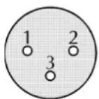
Pin 1 = Ground
Pin 2 = In Phase (+)
Pin 3 = Out of Phase (-)
Floating Balanced Output
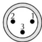

Pin 1 = Open Circuit
Pin 2 = In Phase (+)
Pin 3 = Out of Phase (-)
Electronically Balanced Input
Ground Loop Control
2.8 Ground Loop Control
Strict adherence to the wiring conventions noted above within a fully balanced signal system will yield the best possible results with none of the problems normally associated with interconnected audio equipment. Wherever possible, cable screens should not be connected to any signal pin, but rather left to perform a cable shielding function only.
Where it is not possible to control all of the external cabling, it might become necessary to have the internal electronic ground of your unit separated from the case safety ground. Provision is made internally within the DPR-901ii to separate these two grounds at a convenient point, or to add a suitable impedance network as part of a house system requirement. Please see appendix.
Under no circumstances should the safety ground wire be removed from the mains AC power connector as an interim measure to achieve similar results.
3.0 Controls
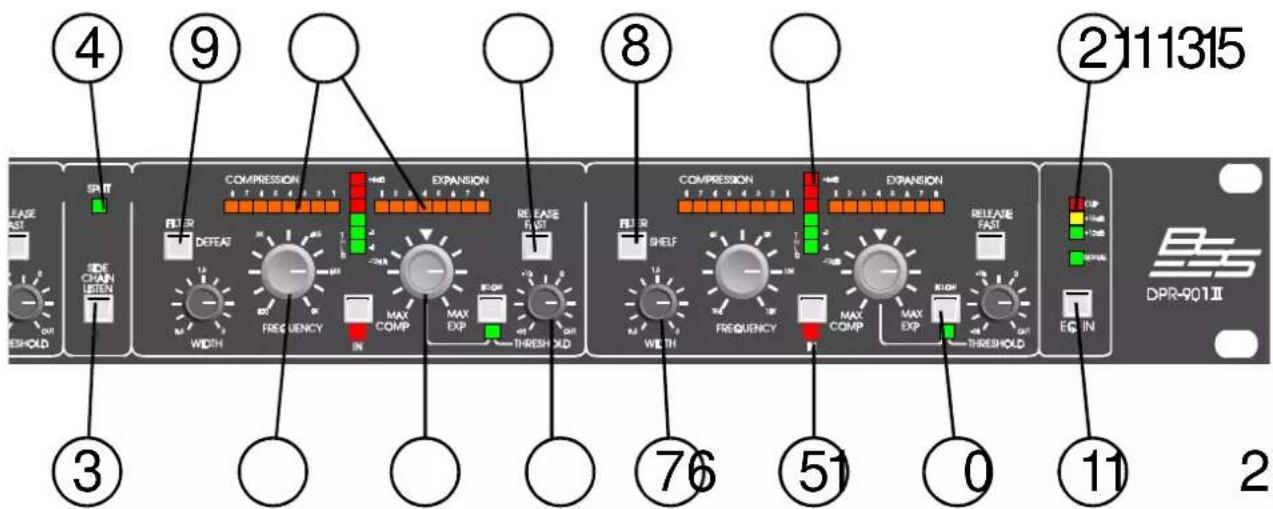
1 EQ IN
When depressed, the processing is engaged and the LED (underneath) lights in confirmation. When released, processing is disabled; the LED is off and the incoming signal passes to the output unchanged and at unity gain (0dB). Note: As the DPR-901ii's entire signal path is bypassed in this mode, signal will be passed to the output even if the AC power is disconnected - or fails. In split mode the input signals are bypassed to their relevant split output.
2 Output Display
The lower green LED displays presence of incoming signal. The three LED bar above shows available headroom. If the uppermost 'CLIP' LED lights (indicating overload), reduce the drive level. Otherwise, check system connections for inadvertent loops causing feedback.
3 SIDE CHAIN LISTEN
Pressing this momentary button sends the side chain audio signal of any active band to the output. This will include any filtering, and allows you to set up the signal that will subsequently be removed or expanded by the dynamics processing.
4 SPLIT led
This led lights to indicate that the split switch on the rear panel is in the 'split' position.
All the remaining controls relate to the four frequency conscious bands. Reading from left to right, these cover Low, low-Mid, high-Mid and High and the controls for the four bands are mainly identical.
Controls
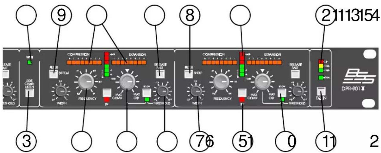
5 IN When depressed, the band is operative. The LED underneath lights. When released, the band is bypassed. This is useful for dropping out effects when they're not needed (without disturbing the other settings), and for A/B comparisons.
6 FREQUENCY Turn to set the centre frequency of the dynamic activity. Note that the range of each band overlaps the next, so for example, the low-Mid control covers the same ground as the upper portion of the bass band and the lower portion of the high-Mid band. This is useful if say, the bass has to provide processing at 60Hz but a different process is also required at 160 and another at 900Hz.
7 WIDTH Controls bandwidth or 'Q'. Turn clockwise to widen or defocus the affected band of frequencies. Turn anti-clockwise to narrow or sharpen the affected band. Irrespective of WIDTH setting, the band is always centered on the frequency set with the FREQUENCY knob (above), covering an equal number of octaves or fractions of an octave either side.
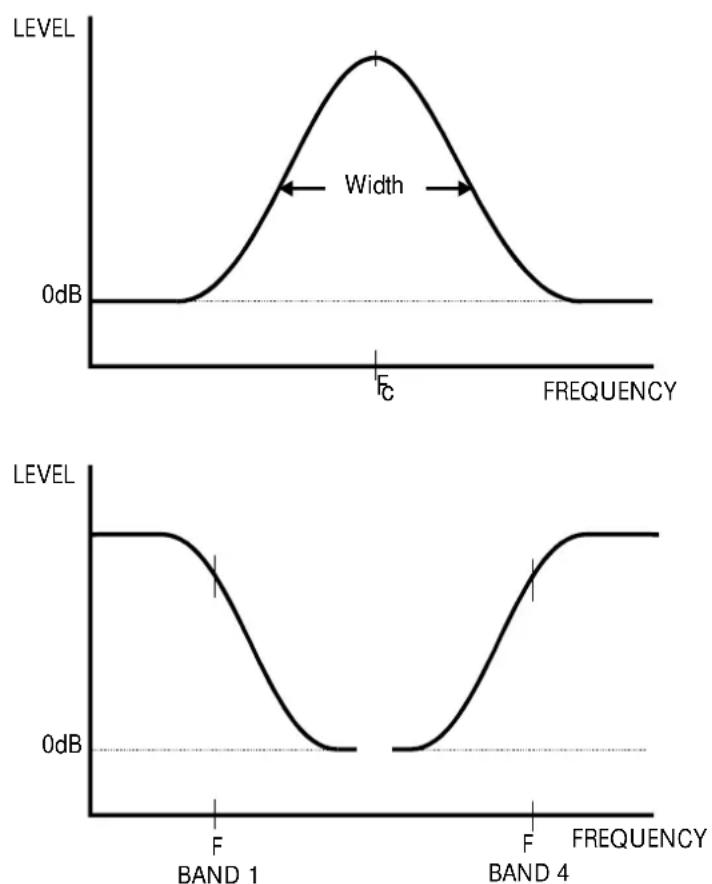
8 FILTER/SHELF (Band one and band four only). Switches the filter from a bell to a shelving response. See fig. 3.1. With the bell response, the process sensitivity is reduced symmetrically either side of the selected centre frequency. When the shelf response is selected, the process sensitivity increases until it reaches a plateau. Thereafter it remains constant below the LF (bass) centre frequency, and above the HF (treble) centre frequency.
Controls
9 FILTER/DEFEAT
(Band two and band three only). Switches the EQ from a bell response to a flat (wide-band) response. With the bell response, the process sensitivity is reduced symmetrically either side of the selected centre frequency. When the Defeat setting is selected by depressing the button, the affected band becomes EQ-less, like a conventional compressor/expander: it responds to all frequencies equally. This facility allows ordinary compression/expansion to be used alongside and in addition to effects established using the three (remaining) bands of frequency sensitive compression/expansion.
10 COMP-EXP
When this control is set centrally (at 12 o'clock), the dynamic effect is nil. When turned to the left, the band is compressed. When turned to the right, the band is expanded. However, expansion or compression is conditional as it only occurs if the signal level is above threshold (or below threshold dependent on switch 14), as indicated on meter 13. The degree of compression or expansion is indicated on meter 11. The compression or expansion ratio progressively increases as the knob is turned away from the centre and is soft-knee close to the centre, becoming harder (more like a limiter) with more extreme settings. Maximum compression is +30dB and maximum expansion is +16dB.
Fig. 3.1 Bell and Shelf Filter Switching
Controls
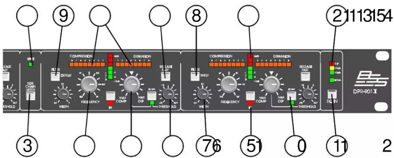
11 Compression/Expansion Display
These horizontal LED displays give an instant, intuitive check on whether the process in each band is active, by how much, and whether it's expansion or compression. The amount of expansion or compression is indicated by an easy-to-memorise 1-8 scale, with '8' indicating maximum (hard) compress or expand.
12 THRESHOLD
Turn to set the signal threshold level above (or below) which the effect is to take place and is used in conjunction with LED meter 11. Turning anti-clockwise reduces the signal level needed to exceed the threshold, and therefore increases sensitivity. Signals exceeding threshold initiate the selected processing. (Above threshold mode, see 12). Turning clockwise increases the signal level needed and reduces sensitivity. When set fully clockwise, the threshold is set to +20dBu.
13 Threshold Display
Shows the input signal level in relation to the threshold you have set. The central orange LED lights dimly as the threshold is reached and then glows increasingly bright as the threshold is exceeded. When the signal causes the red LEDs to be lit, signal is above threshold. The first green LED indicates a signal level 12dB below threshold.
Controls
14 BELOW Threshold
When the switch is released, the processing operates above threshold, that is with compression or expansion being applied only to signal levels that exceed the threshold. When the switch is depressed to select Below, the green led beneath the switch lights. The threshold's sensitivity setting remains the same, but the processing is 'turned on its head' as compression or expansion is now only applied to signals which are below the threshold. Below threshold compression now works like a frequency-sensitive gate in that the further below the threshold the signal is, the more it is attenuated. There being progressively less attenuation as signal level increases to approach the threshold setting. Below threshold expansion acts to boost the selected frequency range up to (but not above) the threshold. The expansion meter 9 will light under these low signal conditions, slowly reducing as the input signal increases towards threshold.
15 FAST RELEASE
When the switch is released, the compress/expand time constants are automatic. This is the normal setting if you're using the DPR-901ii as a leveller or otherwise processing a composite (mixed down) music signal. When depressed for FAST, the compress/expand release time is speeded up. This is likely to be the correct setting for less spectrally dense material, normally single instruments, especially dynamic sources, ie. vocals, percussion and any instruments played percussively.
4.0 Principle of Operation
The DPR-901ii is fundamentally different to ordinary de-essers, Dolby systems and the like because it uses subtractive techniques to control the degree of compression or expansion. This enables the VCA (gain control element) to be kept out of the direct signal path. As a result, the through-going signal is not subjected to the noise and distortion that's intrinsic to even the best VCAs. Moreover, the resultant filtered output exhibits far less of the 'time smearing' that accompanies most conventional units and has at times given equalisation a bad name. In fact, the subtractive VCA technique can only operate correctly if the 'passing through' and 'control' signals at the subtractor are correctly aligned.
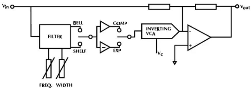
Figure 4.1 shows a simple block diagram that illustrates the principle of operation of subtractive gain reduction and Fig 4.2 that with the addition of filtering and inverter for gain addition or expansion.
Referring to figure 4.1, in operation the main signal path is simply through the single inverting op-amp as the VCA is held at maximum attenuation. When signal exceeds the set threshold level, the inverting VCA is gradually opened, allowing a small ‘subtracting’ signal to pass to the main inverting op-amp. Furthermore, this signal is also conditioned by the filtering effect of the parametric filter. The resultant output is then either reduced in level, or increased in level dependent on the ‘compress/expand’ switch, and it is only those frequencies passed by the filter, that are so processed.
On the DPR-901ii, the threshold control is adjusting the voltage drive level to the VCA, in conjunction with a fixed reference point, whilst the 'compress/expand' switch is replaced with a centre-off compress or
Fig 4.1 Subtractive Gain Reduction
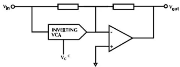
Fig 4.2 Subtractive Gain Reduction or Expansion
flowchart
graph TD
    A["Vin"] --> B["FILTER"]
    B --> C["BELL"]
    B --> D["SHELF"]
    C --> E["COMP"]
    D --> F["EXP"]
    E --> G["INVERTING VCA"]
    F --> G
    G --> H["+"]
    I["Vout"] --> J["Resistor"]
    J --> G
    K["FREQ. WIDTH"] --> B
    L["Ve"] --> G
Principle of Operation
expand level control, whose function is similar to a ratio control on conventional dynamic processors. The DPR-901ii Dynamic Equaliser, with four separate sections of this processing, offers considerable processing performance by adding another variable dimension to conventional equalisation.
5.0 Using the DPR-901ii
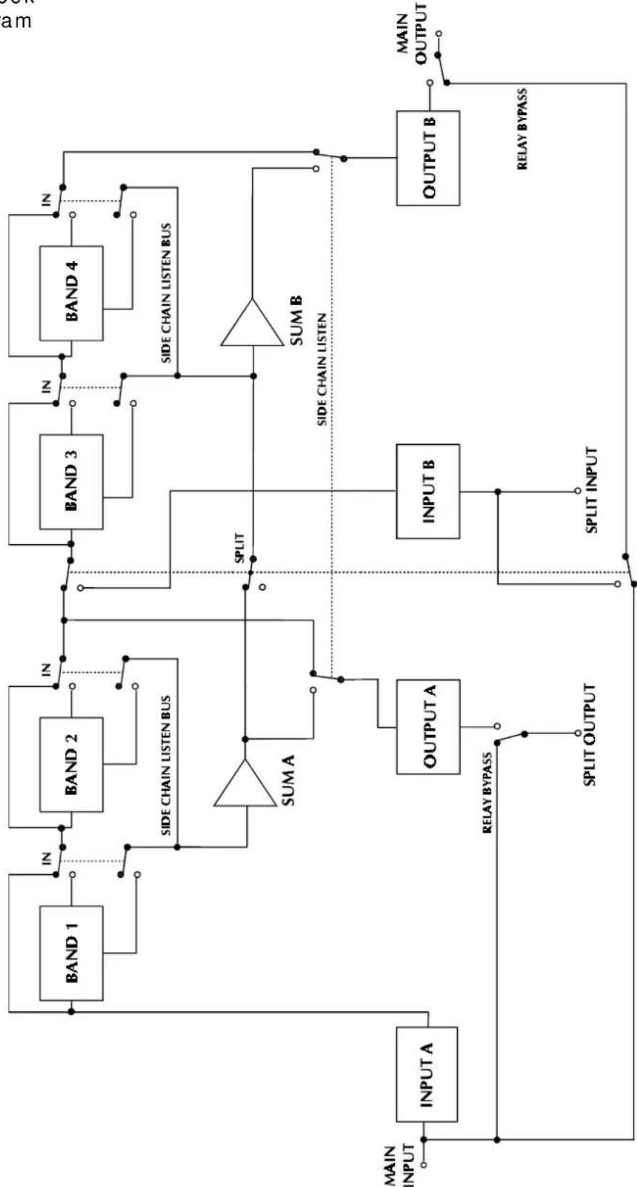
Refer to the block diagram in Fig 5.1 opposite.
We recommend you familiarise yourself with the normal above threshold mode of operation before exercising the below threshold configuration. The latter is more subtle in effect, and requires more precise adjustments of level, especially in expansion.
For high sound quality it's important that you set the input drive correctly, particularly when using the expansion mode. As is common for all electronic equipment, care must be taken to ensure that the input signal does not exceed the maximum internal clipping level (especially when boosted by expansion) and the output headroom meter is therefore an important display. When setting up you must ensure that on one hand, your maximum signal peak does not exceed the 'clip' scale point and on the other, is not so low that it's wasteful of dynamic range. As the optimum drive level depends on the exact processing applied, it should be re-checked after initial setting and any subsequent fine tuning.
To set up the filter controls, the side chain listen switch can be used to listen in to the actual signal that will be subtracted or added by the VCA. This is especially useful if more than one band of processing is being applied, as the overall effect of the filtering can be heard, before the dynamic activity is applied. Only the side chains of those bands that are selected IN will be routed to the output. NOTE: If no bands are selected IN then nothing will be heard when the side chain listen switch is pressed.
With the split switch in the MAIN position, the DPR-901ii is configured as a single four band unit, and the input signal should be plugged into the MAIN input, and the output should be taken from the MAIN output. Side chain listen signals for all bands are routed to the MAIN output. The relay bypass signal is routed from the MAIN input to the MAIN output. The output signal from bands 1 & 2 is available at the SPLIT output, but the SPLIT input is inoperative.
With the split switch in the SPLIT position, the DPR-901ii is effectively split down the middle, and is configured as two independent two band units. The frequency ranges remain unchanged.
For bands 1 & 2, the input signal should be plugged into the MAIN input, and the output signal should be taken from the SPLIT output.
For bands 3 & 4 the input signal should be plugged into the SPLIT input, and the output taken from the MAIN output.
Side chain listen signals are routed to their appropriate output, and the relay bypass directly connects the MAIN input to the SPLIT output, and the SPLIT input to the MAIN output.
5.1 DPR-901ii Block Diagram
flowchart
graph TD
    A["MAIN INPUT"] --> B["INPUT A"]
    B --> C["BAND 1"]
    C --> D["IN"]
    D --> E["BAND 2"]
    E --> F["IN"]
    F --> G["BAND 3"]
    G --> H["IN"]
    H --> I["BAND 4"]
    I --> J["IN"]
    J --> K["SIDE CHAIN LISTEN BUS"]
    K --> L["SUM A"]
    L --> M["SPLIT OUTPUT"]
    M --> N["OUTPUT A"]
    N --> O["INPUT B"]
    O --> P["SPLIT INPUT"]
    P --> Q["OUTPUT B"]
    Q --> R["MAIN OUTPUT"]
    R --> S["RELAY BYPASS"]
    S --> T["SPLIT OUTPUT"]
    T --> U["OUTPUT A"]
    U --> V["SPLIT OUTPUT"]
    V --> W["OUTPUT B"]
    W --> X["RELAY BYPASS"]
    X --> Y["SPLIT OUTPUT"]
    Y --> Z["OUTPUT A"]
    Z --> AA["SPLIT OUTPUT"]
    AA --> AB["OUTPUT B"]
    AB --> AC["SPLIT INPUT"]
    AC --> AD["OUTPUT A"]
    AD --> AE["SPLIT OUTPUT"]
    AE --> AF["OUTPUT B"]
    AF --> AG["SPLIT INPUT"]
    AG --> AH["OUTPUT A"]
    AH --> AI["SPLIT OUTPUT"]
    AI --> AJ["OUTPUT B"]
    AJ --> AK["SPLIT INPUT"]
    AK --> AL["OUTPUT A"]
    AL --> AM["SPLIT OUTPUT"]
    AM --> AN["OUTPUT B"]
    AN --> AO["SPLIT INPUT"]
    AO --> AP["OUTPUT A"]
    AP --> AQ["SPLIT OUTPUT"]
    AQ --> AR["OUTPUT B"]
    AR --> AS["SPLIT INPUT"]
    AS --> AT["OUTPUT A"]
    AT --> AU["SPLIT OUTPUT"]
    AU --> AV["OUTPUT B"]
    AV --> AW["SPLIT INPUT"]
    AW --> AX["OUTPUT A"]
    AX --> AY["SPLIT OUTPUT"]
    AY --> AZ["OUTPUT B"]
    AZ --> BA["SPLIT INPUT"]
    BA --> BB["OUTPUT A"]
    BB --> BC["SPLIT OUTPUT"]
    BC --> BD["OUTPUT B"]
    BD --> BE["SPLIT INPUT"]
    BE --> BF["OUTPUT A"]
    BF --> BG["SPLIT OUTPUT"]
    BG --> BH["OUTPUT B"]
    BH --> BI["SPLIT INPUT"]
    BI --> BJ["OUTPUT A"]
    BJ --> BK["SPLIT OUTPUT"]
    BK --> BL["OUTPUT B"]
    BL --> BM["SPLIT INPUT"]
    BM --> BN["OUTPUT A"]
    BN --> BO["SPLIT OUTPUT"]
    BO --> BP["OUTPUT B"]
    BP --> BQ["SPLIT INPUT"]
    BQ --> BR["OUTPUT A"]
    BR --> BS["SPLIT OUTPUT"]
    BS --> BT["OUTPUT B"]
6.0 Warranty Information
This unit is warranted by BSS Audio to the original end user purchaser against defects in workmanship and the materials used in its manufacture for a period of one year from the date of shipment to the end user.
Faults arising from misuse, unauthorised modifications or accidents are not covered under this warranty. No other warranty is expressed or implied.
If the unit is faulty it should be sent, in its original packaging, to the supplier or your local authorised BSS Audio dealer with shipping prepaid.
You should include a statement listing the faults found. The unit's serial number must be quoted in all correspondence relating to a claim.
We recommend that you record your purchase information here for future reference.
IMPORTANT
Dealer Name:
Dealer Address:
Post/Zip Code:
Dealer Phone No.:
Dealer Contact Name:
Invoice/Receipt No.:
Date of Purchase:
Unit Serial Number:
In keeping with our policy of continued improvement, BSS Audio reserves the right to alter specifications without prior notice.
The DPR-901ii was designed, developed and produced by BSS Audio, Hertfordshire, England.
Please note our phone numbers.
Phone (+44) (0)1707 660667. Fax (+44) (0)1707 660755.
Appendix A
A1 Chassis/0V Link Removal.
NOTE:
Since both the audio inputs and outputs are wired fully balanced we would suggest that you fully recheck all audio wiring for correctness prior to proceeding.
All DPR-901ii units are shipped with the signal 0v/ground connected to the metal chassis via a wire link, and an rf bypass capacitor on the main pcb. The chassis is also directly connected to the (mains) safety ground/Earth. In the unlikely event that you need to remove the signal 0v/ground to chassis link, or if you need to add a small impedance to reduce earth loop currents, then proceed as follows. Please refer to FIG A1.1.
SAFETY NOTE !!
Under no circumstances should the incoming safety ground wire be disconnected from the power line cord or from the internal chassis connection as an alternative to this procedure.
1: Disconnect the mains power cord and remove the unit's top cover.
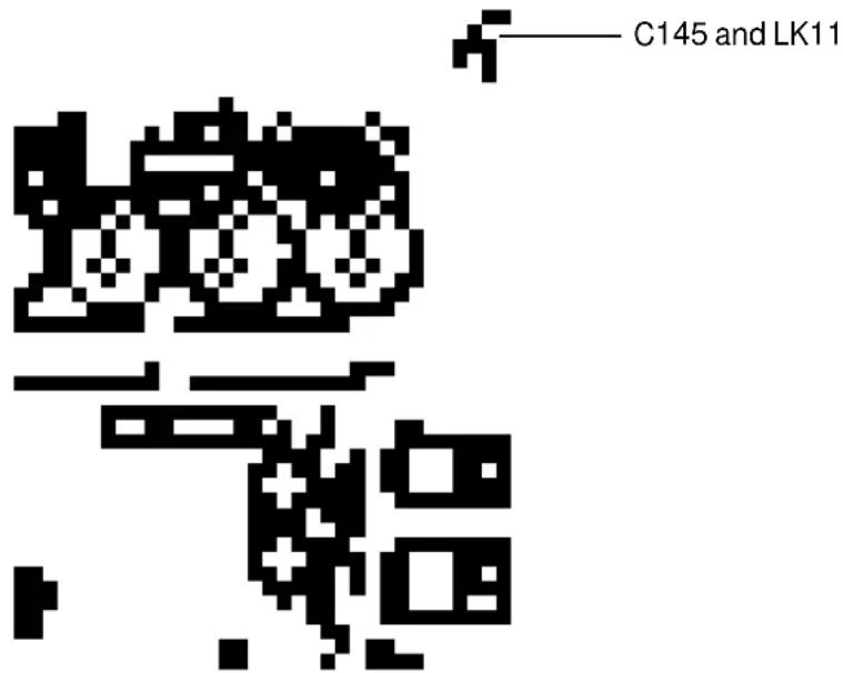
2: Locate LK11 and C145 at the far right hand end of the pcb, next to the transformer. See Fig A1.1 below.
3: Remove and/or replace one or both of these depending on what is required. The wire link provides a direct connection at dc and low frequencies, whilst the capacitor provides a low impedance link at higher frequencies.
4: With both removed, the signal 0v is completely separated from the chassis.
Fig A1.1 Chassis/0V Links
Input pin 1 to Chassis Connection Transient Suppressor Replacement
A2 Input pin 1 to Chassis Connection
There are several options available on the connection between the input XLR pin 1, and the chassis, and the optimum configuration will depend upon the installation, and the equipment it is connected to.
For the main input, positions LK1 and C1 are provided. The factory default is LK1 not fitted, and C1 is 100pF.
For the split input, positions LK6 and C52 are provided. The factory default is LK6 not fitted, and C52 is 100pF.
A2.1 Chassis Links
Main input Chassis Connection
A3 Transient Suppressor Replacement
The primary of the mains transformer within the DPR-901ii is protected against high voltage spike interference by two voltage dependent resistors. These provide a short circuit to voltage peaks in excess of their maximum rating.
Should the DPR-901ii be inadvertently connected to 3 phase line/line voltages, or to 240V when selected to 120V, or any other incorrect voltage, these suppressors are likely to fail in a protective short circuit mode. This will be demonstrated by repeated mains fuse failure when powering up the unit.
Even in this case of extreme overvoltage, the DPR-901ii is protected against failure, and the simple removal of these suppressors will allow the unit to be used again. However, it is important that they are replaced as soon as possible to ensure continued protection.
Figure A3.1 indicates the location and specification for the suppressors.
A3.1 Suppressor location
PCB MOUNTED BEHIND 120V/240V SELECTOR SWITCH
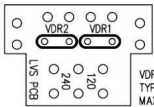
VDR1 & VDR2 Transient suppressor TYPE MULLARD 2322-594-61312 MAX VOLTAGE = 130V RMS
Appendix B Specifications
Input Section
12kohm electronically balanced, +20dBu (+20dBv) maximum input level via a 3 pin male XLR cable plug. Common Mode rejection > -50dB, 20Hz to 20kHz.
Output Section
Electronically balanced and floating, capable of driving +20dBu (+20dBv) into 600ohms or greater via an XLR female cable plug.
Frequency response +/- 0.5dB, 20Hz to 20kHz with all sections bypassed.
Noise < -86dBu, all controls set flat (CCIR 468-2)
Distortion THD < 0.05% 20Hz-20kHz at +15dBu, all controls set flat.
Operating Controls - Each Band
Frequency Band 1 LF Sweepable from 40Hz to 320Hz. Band 2 LM Sweepable from 150Hz to 1600Hz. Band 3 HM Sweepable from 800Hz to 9kHz. Band 4 HF Sweepable from 1.6kHz to 18kHz.
Width Variable from narrow (0.5Oct) to wide (3Oct) Width control is inoperative in SHELF mode.
Filter Shelf Selects shelving EQ response (Bands 1 & 4)
Filter Defeat Selects broadband operation (Bands 2 & 3). A bell-shaped EQ response is the norm for all bands if these switches are 'out'.
Threshold Variable from +20dBu to -30dBu.
Comp/Exp Variable from -30dB compression to +16dB expansion. Soft knee at low settings.
Below Switched in for below threshold processing.
Fast Release Switched out to prevent pumping on composite music mixes. Switched in to respond to highly dynamic signals.
Metering - per channel: 8 horizontal green LEDs indicate compression activity. 8 horizontal red LEDs indicate expansion activity. Note: The 1-8 scaling is for convenience only. It is not a decibel scale. 6 vertical LEDs display signal level (in dB) relative to the threshold control's setting.
Operating Controls - Overall
Band In Switches each band into circuit. EQ In Enables or bypasses the whole system. Output Headroom indicating 4 LED display, indicates CLIP (overload = +20dBu), +15dBu, +10dBu, as well as signal present (-20dBu).
Specifications
Rear Panel Functions and Facilities
Main input Main output Split input Split output
Power AC 40VA, 50/60Hz, 115v/230V selectable externally. IEC mains input socket
General
Size 482mm x 44mm x 292.1mm (19" x 1.75" [1U] x 11.5") overall.
Weight 5kg gross shipping.
Appendix C Glossary
ACTIVE Active electronic circuits are those capable of voltage and power gain by using transistors and integrated circuits. Passive circuits are those which use only resistors, capacitors, transformers, etc.
BALANCED Refers to a 3-wire connection in which two of the wires carry the signal, and the third acts as a shield, tied to chassis ground. The two signal lines are of opposite polarity at any instant, but are at the same (numeric) voltage with respect to ground. Balanced connections are used to reject noise and hum pickup in system inter-connections.
BELL Descriptive term for equalisation cut or boost which occurs symmetrically either side of the centre frequency. The frequency response graph takes on the shape of a (church) bell.
CLIP Another name for overload; when a signal reaches an amplifier's output voltage or current limits. Clipping is not harmful in itself, but produces severe distortion and exacerbates heat-dissipation in the amplifier, its power supply and the speaker(s).
COMPRESSION Making a signal smaller in proportion to its magnitude. Normally this occurs above a threshold that is near or above the average signal magnitude.
The more the signal exceeds the threshold, the more it's reduced, causing all signals above the threshold to be reduced to a similar level. This increases the density of the sound level distribution in time, giving a characteristic 'thickening' effect to the sonics. The ratio of reduction determines how much the variation in signal magnitude is condensed: high (10:1) ratios reduce large (20dB+) variations to scarcely audible fluctuations of less than 2dB. See EXPANSION for a table of ratios.
Compression can also take place below a given threshold, but this facility is rarely if ever found on existing compressors.
dB A unit for expressing the ratio between two signal levels, for comparison purposes. On its own, it has no absolute value. Rather, it's a logarithmic ratio used to express the differences between two amounts or levels. Positive numbers indicate an increase, and negative ones a decrease. Some useful ratios are:
+3dB = double power or 1.5x voltage
+6dB = 4x power; or 2x voltage
+10dB = 10x power; or 3x voltage
+20dB = 100x power; or 10x voltage
dBm The addition of 'm' after dB indicates an absolute scaling for the dB ratio. Instead of a ratio, the dB then becomes a measure of power. 0dBm = a power level of 1 milliwatt into a load of 600 ohms. The corresponding voltage is 778mV (0.778v). In modern audio, the dBm is loosely used to
describe voltage levels, although strictly it only applies to 600 ohm circuits. We recommend you use dBu instead.
dBu or dBv The addition of ‘u’ or ‘v’ after dB indicates an absolute scaling for the dB ratio. 0dBu (or 0dBv) = 778mV or 0.778 volts, and it has no regard to power or impedance. dBu and dBv are widely used for expressing signal voltages in modern audio equipment, where output impedances are low, and input (load) impedances are much higher.
dBV The same as for dBu above, except 0dBV = 1.0 volts. To convert dBV to dBu, simply subtract 2.2dB.
DISTORTION Refers to any modification of a signal which produces new frequency components not present in the original. Harmonic distortion refers to added components that are overtones to the fundamental frequency. Intermodulation distortion creates sum and difference frequencies which are highly objectionable, because they're not harmonically related to the original.
EXPAND Making a signal bigger in proportion to its magnitude. Normally the amount of expansion is described with a plain numerical ratio (eg. 2:1) or in decibels (which express the same ratio), eg. 6dB. Some common ratios are:
3dB: 1.4:1
6dB 2:1
10dB 3:1
20dB 10:1
26dB 20:1
30dB 30:1
See COMPRESS (above) for an explanation of threshold and below threshold expansion.
FREQUENCY The repetition rate of a waveform. The unit of frequency is Hz, and 1 cycle per second is equal to 1Hz. The audio band is generally regarded as spanning the frequencies between 20Hz and 20,000Hz (20kHz).
FREQUENCY RESPONSE Refers to the equipment's relative gain, compared to frequency. Generally expressed as +/- a certain number of dB's from 20Hz to 20kHz.
HEADROOM The amount in dBs, above the normal operating level that can be used before serious distortion commences.
HF High Frequencies, generally 800Hz or 3500Hz up to 20,000Hz.
IMPEDANCE The AC equivalent of resistance. Impedance is measured in ohms, and indicates the amount of drive current required for an input, or the drive capability of an output, at a given signal level.
LEVEL The amplitude of a signal, measured in volts or decibels.
LIMIT Limiting occurs when a compressor having a high ratio, generally 6:1 or more passes a signal that exceeds the equipment's threshold setting. Large variations in peak signal level are 'squashed', typically fluctuating less than 3dB for a 20 to 30dB increase. See EXPAND' (above)for an explanation of compression and thresholds.
LINE LEVEL Generally indicates signals between -10 and +10dBu, or -12 to +8dBV. Mic level refers to levels around -40dBu. Speaker levels are typically +10 to +40dBu.
LF Low frequencies, or Bass, generally between 10Hz and 200 to 800Hz.
OCTAVE A logarithmic unit for expressing frequency ratios. Positive values indicate an increase in frequency, and negative ones a decrease. One octave 'up' the scale is a doubling in frequency. One octave 'down' is half the frequency.
PHASE CHANGE or INVERT See Polarity Reversal
PHASINESS An expression for unpleasant variations in tonal colouration when two or more sound sources are mutually counteracting.
POLARITY REVERSAL A reversal of instantaneous signal polarity, equivalent to a phase shift of 180^ . Same as polarity inversion.
STATE VARIABLE A classic but sophisticated circuit network used for equalisation. It uses more components than budget equaliser circuits, but when applied correctly, it has a smoother phase response, and greater accuracy in the time domain. Moreover, the EQ's operating state (defined by centre frequency, width and gain) is easily swept - as the name 'state variable' implies.
TRANSIENT A sudden burst of energy in an audio signal, which only lasts for a small period of time, relative to the rest of the signal. The level of these transients can often reach 10 times (+20dB) or so above the normal operating level of the equipment, and may cause distortion if the headroom is inadequate.
UNITY GAIN When the output signal level is equal to the input signal level, ie. no amplification or attenuation.
DPR-901ii
User Notes
User Notes

natural_image
Blank grid paper with no text, numbers, or symbols| 1 | 2 | 3 | 4 | 5 | 6 | 7 | 8 | 9 | 10 | 11 | 12 | 13 | 14 | 15 | 16 | |
| 1 | 1 | 1 | 1 | 1 | 1 | 1 | 1 | 1 | 1 | 1 | 1 | 1 | 1 | 1 | 1 | 1 |
| 2 | 2 | 2 | 2 | 2 | 2 | 2 | 2 | 2 | 2 | 2 | 2 | 2 | 2 | 2 | 2 | 2 |
| 3 | 3 | 3 | 3 | 3 | 3 | 3 | 3 | 3 | 3 | 3 | 3 | 3 | 3 | 3 | 3 | 3 |
| 4 | 4 | 4 | 4 | 4 | 4 | 4 | 4 | 4 | 4 | 4 | 4 | 4 | 4 | 4 | 4 | 4 |
- DPR-901ii User's Manual
- Welcome to the DPR-901ii Users Manual
- DPR-901ii ABOVE AND BELOW THRESHOLD DYNAMIC PARAMETRIC EQUALISATION.
- Table Of Contents
- Introduction 4
- Installation 6
- Controls 11
- Introduction
- Features and Facilities
- Installation
- Unpacking
- Mechanical Installation
- Mains Power
- WARNING: THIS APPLIANCE MUST BE EARTHED.
- Voltage Setting Safety Earthing AC Power Fusing
- Voltage Setting
- 90VAC up to 110VAC on the 120V position
- Safety Earthing
- AC Power Fusing
- Audio Connections
- Audio Connections
- Balanced Wiring
- Unbalanced Wiring
- Ground Loop Control
- Ground Loop Control
- Controls
- EQ IN
- Output Display
- SIDE CHAIN LISTEN
- SPLIT led
- Controls
- FILTER/DEFEAT
- COMP-EXP
- THRESHOLD
- Threshold Display
- BELOW Threshold
- FAST RELEASE
- Principle of Operation
- Principle of Operation
- Using the DPR-901ii
- Warranty Information
- IMPORTANT
- Appendix A
- NOTE:
- SAFETY NOTE !!
- Input pin 1 to Chassis Connection Transient Suppressor Replacement
- A2 Input pin 1 to Chassis Connection
- A2.1 Chassis Links
- A3 Transient Suppressor Replacement
- A3.1 Suppressor location
- Appendix B Specifications
- Specifications
- Appendix C Glossary
- DPR-901ii
- User Notes
Brand : BSS Audio
Model : DPR-901II
Category : Uncategorized